
EN-B Seite 02-17
34
Swiss Quality N 1 Webnet ENGLISH
Transcript of EN-B Seite 02-17

Swiss Quality
N1Webnet
EN
GLIS
H

Pliable, transparent grid structures made of stainless steel rope from the
Jakob® INOX LINE series are multifunctional and durable: mounted on railings or
in staircases, they provide support and guidance; on façades, they can be used as
training systems for plants; in large rooms, they will create subtle accents as fi ligreed
partitions. The Jakob® INOX LINE Webnet was subjected to numerous tests and complies
with all applicable standards: As a permanent protective and safety net for bridges or
observation platforms, it is absolutely UV- and weather-resistant, unlike conventional knotted
plastic fi ber nets.
The Jakob® INOX LINE Webnet has the skin-like characteristics of a diaphragm. It can form a
plane surface but can also be tensioned into three-dimensional forms featuring funnel-type, cylin-
drical, or spherical shapes.
SINCE 1904
SwissQuality
N1
© Copyright by Jakob AG, Drahtseilfabrik CH-3555 Trubschachen Switzerland 1988 / 2004
Technical data subject to change.
© Copyright by Atelier Jakob AG/SA, Switzerland
Idea /Conception Atelier Jakob AG/SA, Hannes Jakob SGD CH-1783 Barberêche, Switzerland

Webnet: Intelligent solutions
in architecture and design
The Jakob® INOX LINE Webnet is a
custom-manufactured, premium-qual-
ity product that is highly compatible
with creative contemporary architec-
ture. As part of our extensive, easy-to-
assemble structural wire-rope series, it
is ideal for flexible, intelligent solutions
that address a vast variety of require-
ments: the multifunctional Jakob® INOX
LINE Webnet technology combined with
stainless steel rope, rods, or tubes with
appropriate end connectors (Jakob®
INOX LINE Basic 5.1 Green Solutions G1,
and News X catalogues) not only dis-
creetly fulfills its functions as a protec-
tive and supporting structure but also
provides appeal as an elegant spatial
design element.
Support and protection function
A lake region in western Switzerland with a
safe bird’s-eye view: in the tethered balloon
on a platform at the Lake of Neuenburg,
visitors can ascend to a height of 150 m. The
large “captive balloon” was installed as a tour-
ist attraction in the summer of 2002, when the
Swiss National Exposition (Expo) took place.
The combined support and protection
structure made of rods, wire rope, and the
Jakob® INOX LINE Webnet components cre-
ated an impressive, futuristic takeoff and land-
ing ramp with guaranteed safety factors.
4 5

Webnet compression tape
Webnet perimeter rope
Wire-rope cutters
Webnet sleeves & eye ends
Swaging tools
Assembly aids
Threaded fasteners
Accessories
Tube system
Rod system
Rod holder
Webnet
Suspension rope
Rope-end connectors
Suspension-rope clamps
Webnet C rail
Crossnet
Connecting rod
Crossnet
6 7
37
38
38
38 39
38 39
36
40
41
32 33
34
34
35
30
10 29
30 31
32
37
8 9
8.1 8.2 9.1 9.2 9.3
9.5
8.3 9.4
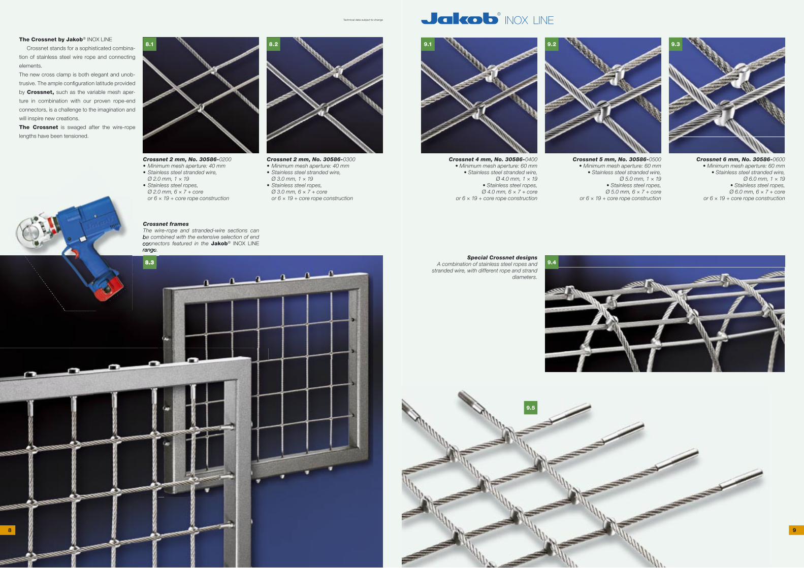
The Crossnet by Jakob® INOX LINE
Crossnet stands for a sophisticated combina-
tion of stainless steel wire rope and connecting
elements.
The new cross clamp is both elegant and unob-
trusive. The ample confi guration latitude provided
by Crossnet, such as the variable mesh aper-
ture in combination with our proven rope-end
connectors, is a challenge to the imagination and
will inspire new creations.
The Crossnet is swaged after the wire-rope
lengths have been tensioned.
Crossnet 2 mm, No. 30586-0200• Minimum mesh aperture: 40 mm• Stainless steel stranded wire, Ø 2.0 mm, 1 × 19• Stainless steel ropes, Ø 2.0 mm, 6 × 7 + core or 6 × 19 + core rope construction
Crossnet 4 mm, No. 30586-0400• Minimum mesh aperture: 60 mm
• Stainless steel stranded wire, Ø 4.0 mm, 1 × 19
• Stainless steel ropes, Ø 4.0 mm, 6 × 7 + core or 6 × 19 + core rope construction
Crossnet 5 mm, No. 30586-0500• Minimum mesh aperture: 60 mm
• Stainless steel stranded wire, Ø 5.0 mm, 1 × 19
• Stainless steel ropes, Ø 5.0 mm, 6 × 7 + core or 6 × 19 + core rope construction
Crossnet 6 mm, No. 30586-0600• Minimum mesh aperture: 60 mm
• Stainless steel stranded wire, Ø 6.0 mm, 1 × 19
• Stainless steel ropes, Ø 6.0 mm, 6 × 7 + core or 6 × 19 + core rope construction
Special Crossnet designsA combination of stainless steel ropes and
stranded wire, with different rope and strand diameters.
Crossnet framesThe wire-rope and stranded-wire sections can be combined with the extensive selection of end connectors featured in the Jakob® INOX LINE range.
Technical data subject to change
Crossnet 2 mm, No. 30586-0300• Minimum mesh aperture: 40 mm• Stainless steel stranded wire, Ø 3.0 mm, 1 × 19• Stainless steel ropes, Ø 3.0 mm, 6 × 7 + core or 6 × 19 + core rope construction
8.3
be combined with the extensive selection of end connectors featured in therange.
8 9
11.1 11.2
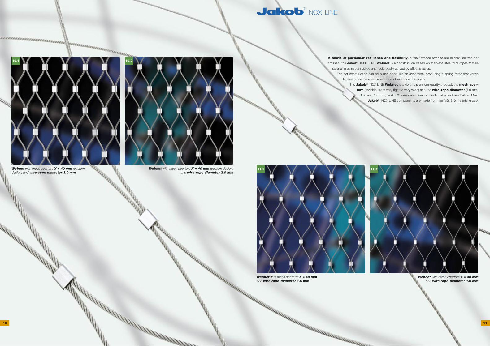
10.1 10.2A fabric of particular resilience and fl exibility, a “net” whose strands are neither knotted nor
crossed: the Jakob® INOX LINE Webnet is a construction based on stainless steel wire ropes that lie
parallel in pairs connected and reciprocally curved by offset sleeves.
The net construction can be pulled apart like an accordion, producing a spring force that varies
depending on the mesh aperture and wire-rope thickness.
The Jakob® INOX LINE Webnet is a vibrant, premium-quality product: the mesh aper-
ture (variable, from very tight to very wide) and the wire-rope diameter (1.0 mm,
1.5 mm, 2.0 mm, and 3.0 mm) determine its functionality and aesthetics. Most
Jakob® INOX LINE components are made from the AISI 316 material group.
Webnet with mesh aperture X = 40 mm and wire rope-diameter 1.5 mm
Webnet with mesh aperture X = 40 mm and wire rope-diameter 1.0 mm
Webnet with mesh aperture X = 40 mm (custom design) and wire-rope diameter 3.0 mm
Webnet with mesh aperture X = 40 mm (custom design) and wire-rope diameter 2.0 mm
10 11

13.1 13.2
13.3
12.1 12.2
12.3
Webnet with 50° mesh angle Webnet with 60° mesh angle (Jakob® standard)
Webnet with extended mesh angle:when stretched, the wire ropes load the sleeve (breaking limit).
The Jakob® INOX LINE Webnet
was tested pursuant to EN 1263-1
for its static and dynamic load-bearing
capacity.
Test data:
• Webnet size: length 7 m × width 5 m
• Webnet rope Ø 3.0 mm, mesh aperture 60 and 100 mm
(horizontal and vertical meshes)
• Webnet rope Ø 2.0 mm, mesh aperture 60 and 100 mm
(horizontal and vertical meshes)
• Ssuspension rope Ø 10.0 mm
• test object: 500-mm steel sphere, mass 100 kg
• drop height of test object: 7 m
Webnet not tensioned (closed) Webnet with 35° mesh angle
Webnet test frame for the determination
of the force/elongation diagrams
The frame is used to determine the elongation of the Webnet in the
height (H) and width (W) directions when exposed to different stretching
forces. The insights form the basis of dimensioning and confi guring the
Webnet and the periphery structure.
12 13

14.2
14.1
14.3
14.4
15.1 15.2
15.3 15.4
The Jakob® INOX LINE Webnet has the skin-like characteristics of a
diaphragm. It can form a plane surface but can also be tensioned into three-
dimensional forms featuring funnel-type, cylindrical, or spherical shapes.
Jakob® INOX LINE, the original:
• custom-manufactured
• fi ligreed, discreet, elegant, fl exible
• multifunctional, compatible with creative architecture
• premium quality, rugged, weather-resistant, non-corroding
14 15

17.1 17.2
16.1
16.2
16.3
16.4
16.5
The multifunctional structural rope system composed of
Jakob® INOX LINE Webnet / Basic 5.1 / Green Solutions
G1 / News X components – stainless steel rope, rods, or
tubes with appropriate end connectors – opens new dimen-
sions and is fully designed for on-site assembly. However, we
can also provide you with turnkey solutions including planning,
engineering, installation blueprints, and assembly.
Jakob® INOX LINE, the original:
• custom-manufactured
• filigreed, discreet, elegant, flexible
• multifunctional, compatible with creative architecture
• premium quality, rugged, weather-resistant, non-corroding
Bern-Belpmoos airport (Switzerland)
• Spherical Webnet shroud
• Webnet rope Ø 2.0 mm, mesh aperture 100 mm
16 17
19.1
19.2
18.1
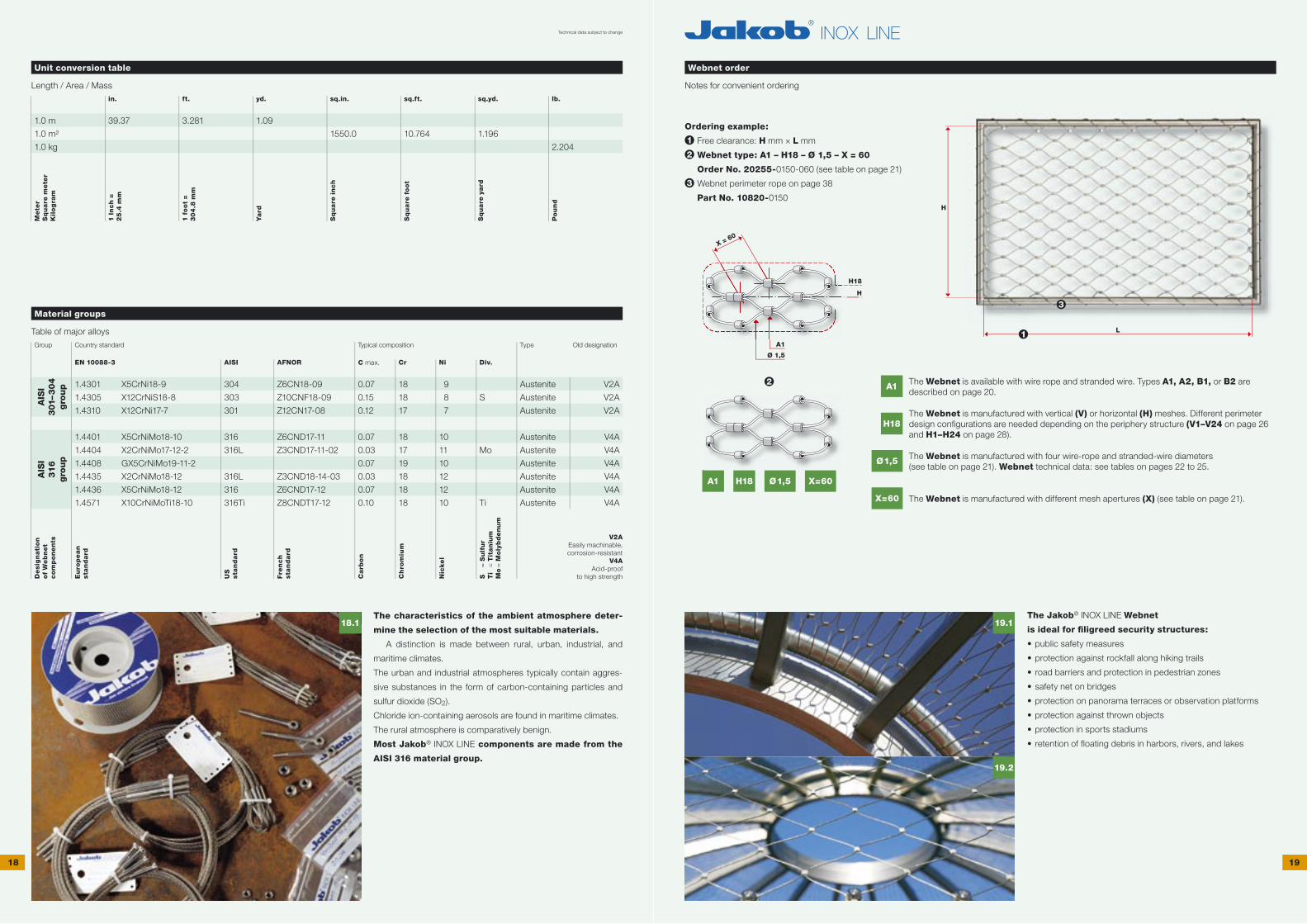
Unit conversion table
Length / Area / Massin. ft. yd. sq.in. sq.ft. sq.yd. lb.
1.0 m
1.0 m²
1.0 kg
39.37 3.281 1.09
1550.0 10.764 1.196
2.204
Me
ter
Sq
uare
me
ter
Kil
og
ram
1 I
nch
=
25
.4 m
m
1 f
oo
t =
30
4.8
mm
Yard
Sq
uare
in
ch
Sq
uare
fo
ot
Sq
uare
yard
Po
un
d
Material groups
Table of major alloysGroup Country standard Typical composition Type Old designation
EN 10088-3 AISI AFNOR C max. Cr Ni Div.
1.4301
1.4305
1.4310
1.4401
1.4404
1.4408
1.4435
1.4436
1.4571
X5CrNi18-9
X12CrNiS18-8
X12CrNi17-7
X5CrNiMo18-10
X2CrNiMo17-12-2
GX5CrNiMo19-11-2
X2CrNiMo18-12
X5CrNiMo18-12
X10CrNiMoTi18-10
304
303
301
316
316L
316L
316
316Ti
Z6CN18-09
Z10CNF18-09
Z12CN17-08
Z6CND17-11
Z3CND17-11-02
Z3CND18-14-03
Z6CND17-12
Z8CNDT17-12
0.07
0.15
0.12
0.07
0.03
0.07
0.03
0.07
0.10
18
18
17
18
17
19
18
18
18
9
8
7
10
11
10
12
12
10
S
Mo
Ti
Austenite
Austenite
Austenite
Austenite
Austenite
Austenite
Austenite
Austenite
Austenite
V2A
V2A
V2A
V4A
V4A
V4A
V4A
V4A
V4A
De
sig
nati
on
of
We
bn
et
co
mp
on
en
ts
Eu
rop
ean
stan
dard
US
st
an
dard
Fre
nch
stan
dard
Carb
on
Ch
rom
ium
Nic
ke
l
S
= S
ulf
ur
Ti
= T
itan
ium
Mo =
Mo
lyb
de
nu
m
V2AEasily machinable,corrosion-resistant
V4AAcid-proof
to high strength
Webnet order
Notes for convenient ordering
The Jakob® INOX LINE Webnet
is ideal for fi ligreed security structures:
• public safety measures
• protection against rockfall along hiking trails
• road barriers and protection in pedestrian zones
• safety net on bridges
• protection on panorama terraces or observation platforms
• protection against thrown objects
• protection in sports stadiums
• retention of floating debris in harbors, rivers, and lakes
The characteristics of the ambient atmosphere deter-
mine the selection of the most suitable materials.
A distinction is made between rural, urban, industrial, and
maritime climates.
The urban and industrial atmospheres typically contain aggres-
sive substances in the form of carbon-containing particles and
sulfur dioxide (SO2).
Chloride ion-containing aerosols are found in maritime climates.
The rural atmosphere is comparatively benign.
Most Jakob® INOX LINE components are made from the
AISI 316 material group.
Ordering example:
1 Free clearance: H mm × L mm
2 Webnet type: A1 – H18 – Ø 1,5 – X = 60
Order No. 20255-0150-060 (see table on page 21)
3 Webnet perimeter rope on page 38
Part No. 10820-0150
A1 The Webnet is available with wire rope and stranded wire. Types A1, A2, B1, or B2 are described on page 20.
H18The Webnet is manufactured with vertical (V) or horizontal (H) meshes. Different perimeter design confi gurations are needed depending on the periphery structure (V1–V24 on page 26 and H1–H24 on page 28).
Ø1,5 The Webnet is manufactured with four wire-rope and stranded-wire diameters (see table on page 21). Webnet technical data: see tables on pages 22 to 25.
X=60 The Webnet is manufactured with different mesh apertures (X) (see table on page 21).
Technical data subject to change
H18
H
X = 60
A1
Ø 1,5
H18A1 Ø1,5 X=60
AIS
I3
01–3
04
gro
up
AIS
I3
16
gro
up
H
L1
3
2
18 19

A B A1 B1A2 B2
A1 B1A2 B2
H
W
60
X
H
W
60
X
The Jakob® INOX LINE Webnet B, made of stainless steel stranded wire
1 × 19 (AISI 316 material group).
Stranded wire 1 × 19 for Webnet stranded wire ø
1.0 mm, 1.5 mm, 2.0 mm, and 3.0 mm
X = mesh aperture60° = standard mesh angle H = mesh aperture heightW = mesh aperture width
The Jakob® INOX LINE Webnet A, made of stainless steel stranded wire, is produced with sleeves or clamps.
Stranded wire / sleeveThe closed sleeve is threaded
onto the stranded wire and swaged.The sleeve looks the same
on both sides.
Material: DIN E-CU sn (tin-plated copper).
Also available in the AISI 316 material group.
Stranded wire / clampThe open special clamp is com-pressed around the strands and
therefore looks different on the op-posite side (see fi g. on page 21).
AISI 316 material group
The Jakob® INOX LINE Webnet A, made of stainless steel rope 6 × 7 + core
and 6 × 19 + core (AISI 316 material group).
Rope 6 × 7 + core for Webnet rope ø
1.0 mm, 1.5 mm, and 2.0 mm
Rope 6 × 19 + core for Webnet rope ø
3.0 mm
X = mesh aperture60° = standard mesh angle H = mesh aperture heightW = mesh aperture width
The Jakob® INOX LINE Webnet A, made of stainless steel rope, is produced with sleeves or clamps.
Wire rope / sleeveThe closed sleeve is threaded
onto the wire ropes and swaged.The sleeve looks the same
on both sides.
Material: DIN E-CU sn (tin-plated copper).
Also available in the AISI 316 material group.
Wire rope / clampThe open special clamp is com-
pressed around the wire ropes and therefore looks different on the op-posite side (see fi g. on page 21).
AISI 316 material group
The Jakob® INOX LINE Webnet,
made of stainless steel
rope 6 × 7 + core and 6 × 19 + core,
is a multifunctional product for all types of protective
applications where aesthetic appearance is also a must.
No. 20255-
Rop
e ø
m
m
Me
sh a
pert
ure X
0100-030
0100-040
0100-050
0100-060
0100-070
0100-080
0150-030
0150-040
0150-050
0150-060
0150-070
0150-080
0150-100
0150-120
0150-140
0150-160
0150-180
0200-050
0200-060
0200-070
0200-080
0200-100
0200-120
0200-140
0200-160
0200-180
0300-060
0300-070
0300-080
0300-100
0300-120
0300-140
0300-160
0300-180
1.0
1.0
1.0
1.0
1.0
1.0
1.5
1.5
1.5
1.5
1.5
1.5
1.5
1.5
1.5
1.5
1.5
2.0
2.0
2.0
2.0
2.0
2.0
2.0
2.0
2.0
3.0
3.0
3.0
3.0
3.0
3.0
3.0
3.0
30
40
50
60
70
80
30
40
50
60
70
80
100
120
140
160
180
50
60
70
80
100
120
140
160
180
60
70
80
100
120
140
160
180
No. 20255- Str
an
de
d w
ire ø
m
m
Me
sh a
pert
ure X
0100-041
0100-051
0100-061
0100-071
0100-081
0150-041
0150-051
0150-061
0150-071
0150-081
0150-101
0150-121
0150-141
0150-161
0150-181
0200-061
0200-071
0200-081
0200-101
0200-121
0200-141
0200-161
0200-181
0300-071
0300-081
0300-101
0300-121
0300-141
0300-161
0300-181
1.0
1.0
1.0
1.0
1.0
1.5
1.5
1.5
1.5
1.5
1.5
1.5
1.5
1.5
1.5
2.0
2.0
2.0
2.0
2.0
2.0
2.0
2.0
3.0
3.0
3.0
3.0
3.0
3.0
3.0
40
50
60
70
80
40
50
60
70
80
100
120
140
160
180
60
70
80
100
120
140
160
180
70
80
100
120
140
160
180
No. 20256-
Rop
e ø
m
m
Me
sh a
pert
ure X
0100-030
0100-040
0100-050
0100-060
0100-070
0100-080
0150-030
0150-040
0150-050
0150-060
0150-070
0150-080
0150-100
0150-120
0150-140
0150-160
0150-180
0200-050
0200-060
0200-070
0200-080
0200-100
0200-120
0200-140
0200-160
0200-180
0300-060
0300-070
0300-080
0300-100
0300-120
0300-140
0300-160
0300-180
1.0
1.0
1.0
1.0
1.0
1.0
1.5
1.5
1.5
1.5
1.5
1.5
1.5
1.5
1.5
1.5
1.5
2.0
2.0
2.0
2.0
2.0
2.0
2.0
2.0
2.0
3.0
3.0
3.0
3.0
3.0
3.0
3.0
3.0
30
40
50
60
70
80
30
40
50
60
70
80
100
120
140
160
180
50
60
70
80
100
120
140
160
180
60
70
80
100
120
140
160
180
No. 20256- Str
an
de
d w
ire ø
m
m
Me
sh a
pert
ure X
0100-041
0100-051
0100-061
0100-071
0100-081
0150-041
0150-051
0150-061
0150-071
0150-081
0150-101
0150-121
0150-141
0150-161
0150-181
0200-061
0200-071
0200-081
0200-101
0200-121
0200-141
0200-161
0200-181
0300-071
0300-081
0300-101
0300-121
0300-141
0300-161
0300-181
1.0
1.0
1.0
1.0
1.0
1.5
1.5
1.5
1.5
1.5
1.5
1.5
1.5
1.5
1.5
2.0
2.0
2.0
2.0
2.0
2.0
2.0
2.0
3.0
3.0
3.0
3.0
3.0
3.0
3.0
40
50
60
70
80
40
50
60
70
80
100
120
140
160
180
60
70
80
100
120
140
160
180
70
80
100
120
140
160
180
The Jakob® INOX LINE Webnet,
made of stainless steel
stranded wire 1 × 19,
is suitable for applications involving high shear/scour forces
and/or high tensile forces within the rope structure.
The Jakob® INOX LINE Webnet is a vibrant, premium-quality product
made from the stainless AISI 316 material group: the mesh aperture X
(variable, from very tight to very wide), the wire-rope diameter (1.0 mm,
1.5 mm, 2.0 mm, and 3.0 mm), and the choice of wire rope or stranded
wire determine functionality and aesthetics.
Webnet types
Technical data subject to change
20 21
A1
B1
H
W
60
X
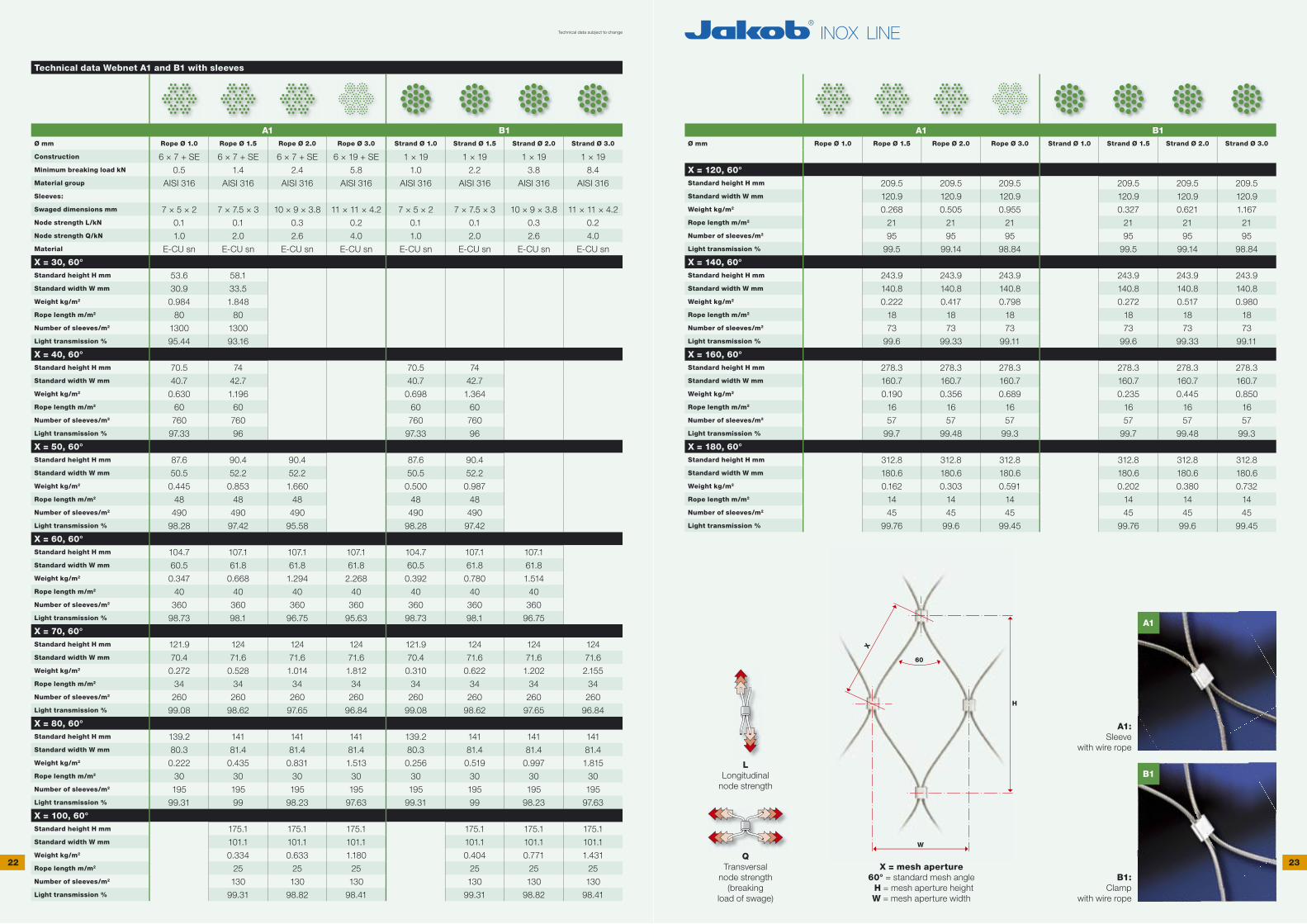
Technical data Webnet A1 and B1 with sleeves
A1 B1Ø mm Rope Ø 1.0 Rope Ø 1.5 Rope Ø 2.0 Rope Ø 3.0 Strand Ø 1.0 Strand Ø 1.5 Strand Ø 2.0 Strand Ø 3.0
Construction 6 × 7 + SE 6 × 7 + SE 6 × 7 + SE 6 × 19 + SE 1 × 19 1 × 19 1 × 19 1 × 19Minimum breaking load kN 0.5 1.4 2.4 5.8 1.0 2.2 3.8 8.4 Material group AISI 316 AISI 316 AISI 316 AISI 316 AISI 316 AISI 316 AISI 316 AISI 316Sleeves:
Swaged dimensions mm 7 × 5 × 2 7 × 7.5 × 3 10 × 9 × 3.8 11 × 11 × 4.2 7 × 5 × 2 7 × 7.5 × 3 10 × 9 × 3.8 11 × 11 × 4.2Node strength L/kN 0.1 0.1 0.3 0.2 0.1 0.1 0.3 0.2Node strength Q/kN 1.0 2.0 2.6 4.0 1.0 2.0 2.6 4.0Material E-CU sn E-CU sn E-CU sn E-CU sn E-CU sn E-CU sn E-CU sn E-CU sn
X = 30, 60° wStandard height H mm 53.6 58.1Standard width W mm 30.9 33.5Weight kg/m2 0.984 1.848Rope length m/m2 80 80Number of sleeves/m2 1300 1300Light transmission % 95.44 93.16
X = 40, 60°Standard height H mm 70.5 74 70.5 74Standard width W mm 40.7 42.7 40.7 42.7Weight kg/m2 0.630 1.196 0.698 1.364Rope length m/m2 60 60 60 60Number of sleeves/m2 760 760 760 760Light transmission % 97.33 96 97.33 96
X = 50, 60°Standard height H mm 87.6 90.4 90.4 87.6 90.4Standard width W mm 50.5 52.2 52.2 50.5 52.2Weight kg/m2 0.445 0.853 1.660 0.500 0.987Rope length m/m2 48 48 48 48 48Number of sleeves/m2 490 490 490 490 490Light transmission % 98.28 97.42 95.58 98.28 97.42
X = 60, 60°Standard height H mm 104.7 107.1 107.1 107.1 104.7 107.1 107.1Standard width W mm 60.5 61.8 61.8 61.8 60.5 61.8 61.8Weight kg/m2 0.347 0.668 1.294 2.268 0.392 0.780 1.514Rope length m/m2 40 40 40 40 40 40 40Number of sleeves/m2 360 360 360 360 360 360 360Light transmission % 98.73 98.1 96.75 95.63 98.73 98.1 96.75
X = 70, 60°Standard height H mm 121.9 124 124 124 121.9 124 124 124Standard width W mm 70.4 71.6 71.6 71.6 70.4 71.6 71.6 71.6Weight kg/m2 0.272 0.528 1.014 1.812 0.310 0.622 1.202 2.155Rope length m/m2 34 34 34 34 34 34 34 34Number of sleeves/m2 260 260 260 260 260 260 260 260Light transmission % 99.08 98.62 97.65 96.84 99.08 98.62 97.65 96.84
X = 80, 60°Standard height H mm 139.2 141 141 141 139.2 141 141 141Standard width W mm 80.3 81.4 81.4 81.4 80.3 81.4 81.4 81.4Weight kg/m2 0.222 0.435 0.831 1.513 0.256 0.519 0.997 1.815Rope length m/m2 30 30 30 30 30 30 30 30Number of sleeves/m2 195 195 195 195 195 195 195 195Light transmission % 99.31 99 98.23 97.63 99.31 99 98.23 97.63
X = 100, 60°Standard height H mm 175.1 175.1 175.1 175.1 175.1 175.1Standard width W mm 101.1 101.1 101.1 101.1 101.1 101.1Weight kg/m2 0.334 0.633 1.180 0.404 0.771 1.431Rope length m/m2 25 25 25 25 25 25Number of sleeves/m2 130 130 130 130 130 130Light transmission % 99.31 98.82 98.41 99.31 98.82 98.41
A1 B1Ø mm Rope Ø 1.0 Rope Ø 1.5 Rope Ø 2.0 Rope Ø 3.0 Strand Ø 1.0 Strand Ø 1.5 Strand Ø 2.0 Strand Ø 3.0
X = 120, 60°Standard height H mm 209.5 209.5 209.5 209.5 209.5 209.5Standard width W mm 120.9 120.9 120.9 120.9 120.9 120.9Weight kg/m2 0.268 0.505 0.955 0.327 0.621 1.167Rope length m/m2 21 21 21 21 21 21Number of sleeves/m2 95 95 95 95 95 95Light transmission % 99.5 99.14 98.84 99.5 99.14 98.84
X = 140, 60°Standard height H mm 243.9 243.9 243.9 243.9 243.9 243.9Standard width W mm 140.8 140.8 140.8 140.8 140.8 140.8Weight kg/m2 0.222 0.417 0.798 0.272 0.517 0.980Rope length m/m2 18 18 18 18 18 18Number of sleeves/m2 73 73 73 73 73 73Light transmission % 99.6 99.33 99.11 99.6 99.33 99.11
X = 160, 60°Standard height H mm 278.3 278.3 278.3 278.3 278.3 278.3Standard width W mm 160.7 160.7 160.7 160.7 160.7 160.7Weight kg/m2 0.190 0.356 0.689 0.235 0.445 0.850Rope length m/m2 16 16 16 16 16 16Number of sleeves/m2 57 57 57 57 57 57Light transmission % 99.7 99.48 99.3 99.7 99.48 99.3
X = 180, 60°Standard height H mm 312.8 312.8 312.8 312.8 312.8 312.8Standard width W mm 180.6 180.6 180.6 180.6 180.6 180.6Weight kg/m2 0.162 0.303 0.591 0.202 0.380 0.732Rope length m/m2 14 14 14 14 14 14Number of sleeves/m2 45 45 45 45 45 45Light transmission % 99.76 99.6 99.45 99.76 99.6 99.45
LLongitudinal
node strength
QTransversal
node strength (breaking
load of swage)
X = mesh aperture60° = standard mesh angle H = mesh aperture heightW = mesh aperture width
A1:Sleeve
with wire rope
B1:Clamp
with wire rope
Technical data subject to change
22 23

A2
B2
H
W
60
X
Technical data Webnet A2 and B2 with clamps
A2 B2Ø mm Rope Ø 1.0 Rope Ø 1.5 Rope Ø 2.0 Rope Ø 3.0 Strand Ø 1.0 Strand Ø 1.5 Strand Ø 2.0 Strand Ø 3.0
Construction 6 × 7 + SE 6 × 7 + SE 6 × 7 + SE 6 × 19 + SE 1 × 19 1 × 19 1 × 19 1 × 19Minimum breaking load kN 0.5 1.4 2.4 5.8 1.0 2.2 3.8 8.4 Material group AISI 316 AISI 316 AISI 316 AISI 316 AISI 316 AISI 316 AISI 316 AISI 316Clamps:
Dimensions mm 7 × 5 × 2 7 × 7.5 × 3 10 × 9 × 3.8 11 × 11 × 4.2 7 × 5 × 2 7 × 7.5 × 3 10 × 9 × 3.8 11 × 11 × 4.2Node strength L/kN 0.1 0.1 0.3 0.2 0.1 0.1 0.3 0.2Node strength Q/kN 1.0 2.0 2.6 4.0 1.0 2.0 2.6 4.0Material AISI 316 AISI 316 AISI 316 AISI 316 AISI 316 AISI 316 AISI 316 AISI 316
X = 30, 60° wStandard height H mm 53.6 58.1Standard width W mm 30.9 33.5Weight kg/m2 0.984 1.848Rope length m/m2 80 80Number of clamps/m2 1300 1300Light transmission % 95.44 93.16
X = 40, 60°Standard height H mm 70.5 74 70.5 74Standard width W mm 40.7 42.7 40.7 42.7Weight kg/m2 0.630 1.196 0.698 1.364Rope length m/m2 60 60 60 60Number of clamps/m2 760 760 760 760Light transmission % 97.33 96 97.33 96
X = 50, 60°Standard height H mm 87.6 90.4 90.4 87.6 90.4Standard width W mm 50.5 52.2 52.2 50.5 52.2Weight kg/m2 0.445 0.853 1.660 0.500 0.987Rope length m/m2 48 48 48 48 48Number of clamps/m2 490 490 490 490 490Light transmission % 98.28 97.42 95.58 98.28 97.42
X = 60, 60°Standard height H mm 104.7 107.1 107.1 107.1 104.7 107.1 107.1Standard width W mm 60.5 61.8 61.8 61.8 60.5 61.8 61.8Weight kg/m2 0.347 0.668 1.294 2.268 0.392 0.780 1.514Rope length m/m2 40 40 40 40 40 40 40Number of clamps/m2 360 360 360 360 360 360 360Light transmission % 98.73 98.1 96.75 95.63 98.73 98.1 96.75
X = 70, 60°Standard height H mm 121.9 124 124 124 121.9 124 124 124Standard width W mm 70.4 71.6 71.6 71.6 70.4 71.6 71.6 71.6Weight kg/m2 0.272 0.528 1.014 1.812 0.310 0.622 1.202 2.155Rope length m/m2 34 34 34 34 34 34 34 34Number of clamps/m2 260 260 260 260 260 260 260 260Light transmission % 99.08 98.62 97.65 96.84 99.08 98.62 97.65 96.84
X = 80, 60°Standard height H mm 139.2 141 141 141 139.2 141 141 141Standard width W mm 80.3 81.4 81.4 81.4 80.3 81.4 81.4 81.4Weight kg/m2 0.222 0.435 0.831 1.513 0.256 0.519 0.997 1.815Rope length m/m2 30 30 30 30 30 30 30 30Number of clamps/m2 195 195 195 195 195 195 195 195Light transmission % 99.31 99 98.23 97.63 99.31 99 98.23 97.63
X = 100, 60°Standard height H mm 175.1 175.1 175.1 175.1 175.1 175.1Standard width W mm 101.1 101.1 101.1 101.1 101.1 101.1Weight kg/m2 0.321 0.607 1.141 0.391 0.745 1.392Rope length m/m2 25 25 25 25 25 25Number of clamps/m2 130 130 130 130 130 130Light transmission % 99.31 98.82 98.41 99.31 98.82 98.41
A2 B2Ø mm Rope Ø 1.0 Rope Ø 1.5 Rope Ø 2.0 Rope Ø 3.0 Strand Ø 1.0 Strand Ø 1.5 Strand Ø 2.0 Strand Ø 3.0
X = 120, 60°Standard height H mm 209.5 209.5 209.5 209.5 209.5 209.5Standard width W mm 120.9 120.9 120.9 120.9 120.9 120.9Weight kg/m2 0.258 0.485 0.927 0.317 0.601 1.139Rope length m/m2 21 21 21 21 21 21Number of clamps/m2 95 95 95 95 95 95Light transmission % 99.5 99.14 98.84 99.5 99.14 98.84
X = 140, 60°Standard height H mm 243.9 243.9 243.9 243.9 243.9 243.9Standard width W mm 140.8 140.8 140.8 140.8 140.8 140.8Weight kg/m2 0.215 0.402 0.776 0.265 0.502 0.958Rope length m/m2 18 18 18 18 18 18Number of clamps/m2 73 73 73 73 73 73Light transmission % 99.6 99.33 99.11 99.6 99.33 99.11
X = 160, 60°Standard height H mm 278.3 278.3 278.3 278.3 278.3 278.3Standard width W mm 160.7 160.7 160.7 160.7 160.7 160.7Weight kg/m2 0.184 0.344 0.671 0.229 0.433 0.832Rope length m/m2 16 16 16 16 16 16Number of clamps/m2 57 57 57 57 57 57Light transmission % 99.7 99.48 99.3 99.7 99.48 99.3
X = 180, 60°Standard height H mm 312.8 312.8 312.8 312.8 312.8 312.8Standard width W mm 180.6 180.6 180.6 180.6 180.6 180.6Weight kg/m2 0.157 0.294 0.577 0.197 0.371 0.718Rope length m/m2 14 14 14 14 14 14Number of clamps/m2 45 45 45 45 45 45Light transmission % 99.76 99.6 99.45 99.76 99.6 99.45
LLongitudinal
node strength
QTransversal
node strength (breaking
load of swage)
X = mesh aperture60° = standard mesh angle H = mesh aperture heightW = mesh aperture width
A1:Sleeve
with wire rope
B1:Clamp
with wire rope
Technical data subject to change
24 25

27.1 27.2 27.3
27.5 27.6 27.7
27.4
Possible perimeter types for Webnet, vertical mesh
V1 V2 V3 V4 V5 V6
V7 V8 V9 V10 V11 V12
V13 V14 V15 V16 V17 V18
V19 V20 V21 V22 V23 V24
Vertical mesh perimeter: open at top with wire-rope end pairs
Vertical mesh perimeter: closed with uncompressed sleeves at top
Webnet V: vertical mesh
Vertical mesh perimeter: with uncompressed sleeves at right
Vertical mesh perimeter: closed with uncompressed sleeves at bottom
Vertical mesh perimeter: closed with Webnet eye ends at bottom
Selection criteria for perimeter confi guration V1 to V24
• Construction of periphery structure, such as suspension ropes (p. 30/31), tubular frame (p. 32/33), rod system (p. 34/35), or Webnet C rail (p. 37)
• Overall dimensions of Webnet
• Assembly-related reasons
• Magnitude of Webnet pretension forces
Some selection criteria for vertical (V) or horizontal (H) Webnet mesh orientation
• Architectural considerations
• Vertical meshes are less suitable for climbing (safety factor load)
• Assembly-related reasons (tight radii always require vertical meshes)
• When the Webnet is tensioned, the forces are greater in the mesh height direction than in the mesh width direction.
Technical data subject to change
26 27

29.1 29.2 29.3
29.5 29.6 29.7
29.4
Possible Webnet perimeter types, horizontal mesh
H1 H2 H3
H4 H5 H6
H7 H8 H9
H10 H11 H12
H13 H14 H15
H16 H17 H18
H19 H20 H21
H22 H23 H24
Horizontal mesh perimeter: closed with uncompressed sleeves at right
Horizontal mesh perimeter: with uncompressed sleeves at bottom
Webnet H: horizontal mesh
Horizontal mesh perimeter: open at left with wire-rope end pairs
Horizontal mesh perimeter: closed with uncompressed sleeves at left
Horizontal mesh perimeter: closed with Webnet eye ends at left
Technical data subject to change
Selection criteria for perimeter confi guration H1 to H24
• Construction of periphery structure, such as suspension ropes (p. 30/31), tubular frame (p. 32/33), rod system (p. 34/35), or Webnet C rail (p. 37)
• Overall dimensions of Webnet
• Assembly-related reasons
• Magnitude of Webnet pretension forces
Some selection criteria for vertical (V) or horizontal (H) Webnet mesh orientation
• Architectural considerations
• Vertical meshes are less suitable for climbing (safety factor load)
• Assembly-related reasons (tight radii always require vertical meshes)
• When the Webnet is tensioned, the forces are greater in the mesh height direction than in the mesh width direction.
28 29

30 31
Suspension rope
Construction 6 × 7 + core AISI 316 material groupPart No. Rope ø
mmWeight kg/100 m
Minimum breaking load kN
10820-0600
10820-0800
6.0
8.0
13.0
23.0
19.0
38.0
Wire-rope cutter
Type C12Part No. Max. rope ø
mmLength mm
30740-0800 8.0 500
VISSLINE® external thread end, right-hand
Only for rope No. 10820-Breaking load: 90% of minimum wire-rope breaking load
AISI 316 material group
Part No. For rope ø mm
amm
b1 mm
b2 mm
c mm
ø d mm
30948-0600-30
30948-0600-60
30948-0800-30
30948-0800-60
6.0
6.0
8.0
8.0
M8 × 30
M8 × 60
M10 × 30
M10 × 60
15.0
15.0
15.0
15.0
45
75
45
75
30
60
30
60
7.2
7.2
9.0
9.0
Swaged external thread end, right-hand
Breaking load: 90% of minimum wire-rope breaking load AISI 316 material groupPart No. For rope ø
mmLength of threadmm
b mm
c mm
ø d mm
30850-0600-030
30850-0600-060
30850-0600-080
30850-0800-080
30850-0800-120
6.0
6.0
6.0
8.0
8.0
M10 × 30
M10 × 60
M10 × 80
M12 × 80
M12 × 120
85
115
135
160
200
30
60
80
80
120
10
10
10
13
13
Dimension b is enlarged by 3 to 6% during the swaging process.
Assembly length
Assembly length
Screwed external thread ends LT1, right-hand
For on-site assembly with rope No. 10820-Breaking load: 90% of minimum wire-rope breaking load
AISI 316 material group
Part No. For rope ø mm
a × length of threadmm
ø d1 mm
ø d2 mm
sw mm
b1 mm
b2 mm
c mm
31826-0600-030
31826-0600-060
31826-0600-031
31826-0600-061
31826-0600-081
31826-0800-061
31826-0800-081
31826-0800-082
31826-0800-120
6.0
6.0
6.0
6.0
6.0
8.0
8.0
8.0
8.0
M8 × 30
M8 × 60
M10 × 30
M10 × 60
M10 × 80
M10 × 60
M10 × 80
M12 × 80
M12 × 120
14
14
14
14
14
22
22
22
22
17.1
17.1
25.4
25.4
25.4
25.4
25.4
25.4
25.4
15
15
15
15
15
22
22
22
22
92
122
92
122
142
140
160
160
200
62
62
62
62
62
80
80
80
80
30
60
30
60
80
60
80
80
120
Not suitable for stranded wire No. 10810-
Correct assembly and the choice of the proper wire-rope diameter are the responsibility of the user.Only Jakob rope No. 10820- assures full functionality.
Turnbuckle with MONOFORK, swaged
Breaking load: 90% of minimum wire-rope breaking load AISI 316 material groupTurnbuckle body (b2): chrome-plated brass
Part No. Rope ømm
amm
b1 mm
b2 mm
ø d1 mm
e mm
f mm
g mm
h mm
Rangemm
30870-0600-01
30870-0800-01
6.0
8.0
M10
M12
319.5
377
140
160
9
12
10.5
18
25.5
32
12
16.3
21.5
30
60
59
50
49
Tensioning range information: The external thread ends are both screwed in halfway.Caution: The minimal screw insertion depth is 1.5 × thread Ø (M8 = 12 mm).
= make longer (relax)
= make shorter (tension)
Turnbuckle with MONOFORK, screwed
For on-site assembly with rope No. 10820-Breaking load: 90% of minimum wire-rope breaking load
AISI 316 material groupTurnbuckle body (b2): chrome-plated brass
Part No. Rope ømm
Gewinde b1 mm
b2 mm
ø d mm
e mm
f mm
g mm
h mm
Rangemm
30822-0600-01
30822-0800-01
6.0
8.0
M10
M12
327.5
385
140
160
9
12
10.5
18
25.5
32
12
16.3
21.5
30
60
59
50
49
Tensioning range information: The external thread ends are both screwed in halfway.Caution: The minimal screw insertion depth is 1.5 × thread Ø (M8 = 12 mm).
= make longer (relax)
= make shorter (tension)
Assembly length
Assembly length
Technical data subject to change
31
c
b
a
ø d
c
b2
b1
a
ø d
b1
b2fe
g
h
ø d1
a
b2
b1
fe
g ød
a
b2
ø d1a
csw
b1
ø d2

32 33
33.1
Suspension-rope clamp
AISI 316 material groupPart No. For rope ø
mm
30858-0600-10
30858-0800-10
6.0
8.0
Adjustable suspension-rope clamp
AISI 316 material groupPart No. For external thread
mm
30858-0600-11
30858-0600-12
M8
M10
Webnet wire-rope clamp G1
For attachment to mounting structure suspension rope AISI 316 material groupPart No. Hole type For Webnet rope ø
mm
30920-0400-00
30920-0400-05
Through hole for M8
For M5 screw with countersunk head
1.5–3.0
1.5–3.0
Tube, ground
Plug-in Webnet tubular frame for on-site assembly AISI 316 material groupPart No. b1
mmø d1 mm
k mm
30924-0017-01
30924-0026-01
max. 2500
max. 2500
17.2
26.9
1.6
2.0
Tube elbow, ground
Plug-in Webnet tubular frame for on-site assembly AISI 316 material groupPart No. ø d1
mmø d2 mm
k mm
b2mm
b3mm
30924-0017-10
30924-0026-10
17.2
26.9
12
21.7
1.6
2.0
100
100
50
50
Tube connector
Connects two tubes, removable AISI 316 material groupPart No. For tube ø
mmbmm
30924-0017-20
30924-0026-20
17.2
26.9
100
100
Tube holder
For the assembly of tubes or prefabricated tubular frames AISI 316 material groupPart No. For tube ø
mmb1 mm
b2 mm
c mm
30924-0017-30
30924-0017-31
30924-0017-32
30924-0026-30
30924-0026-31
30924-0026-32
17.2
17.2
17.2
26.9
26.9
26.9
68.1
85.1
110.1
73
90
115
58
75
100
58
75
100
Variable
Variable
Variable
Variable
Variable
Variable
Welded Webnet tubular frame
Fully strung tubular frames according to your drawings AISI 316 material groupPart No. For tube ø
mm
30924-0017-40
30924-0026-40
17.2
26.9
Welded Webnet tubular frame
Fully strung tubular frames according to your
needs, with the matching assembly accessories
for attachment to mounting structure.
What we need from you:
• dimensioned drawing of frame with
tube Ø 17.2 or 26.9 mm
• Webnet order No. with rope Ø and mesh
aperture X, Type A1, A2 or B1, B2
• vertical mesh V or horizontal mesh H
• number of tube holders and spacers
• description of mounting surface
• see ordering example on page 19
Technical data subject to change
For rope ø
for externalthread
For rope ø
For external thread mm
M8
M10
Webnet wire-rope clamp G1
For attachment to mounting structure suspension ropeHole type
for externalthread
For M5 screw with countersunk head
mm
1.5–3.0
1.5–3.0
For Webnet rope ø For Webnet rope ø
1.5–3.0
For Webnet rope ø For Webnet rope ø
ø 40
b2b3
b2
b3
b1
ød1
k
ø d2
ø d1
b
M8
ø 40
M8
8
ø 20
ø 50
20 b2
M8 ø 20
6 3
c b1
26 M829,5
1525 M10
5
M8
225
M8
1525
34 35
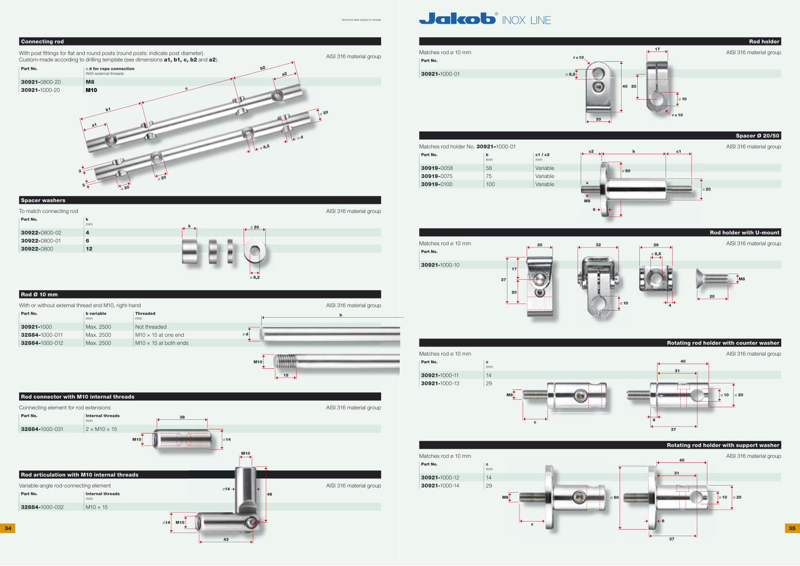
Connecting rod
With post fi ttings for fl at and round posts (round posts: indicate post diameter). Custom-made according to drilling template (see dimensions a1, b1, c, b2 and a2).
AISI 316 material group
Part No. ø d for rope connection With external threads
30921-0800-20
30921-1000-20
M8
M10
Spacer washers
To match connecting rod AISI 316 material groupPart No. k
mm
30922-0800-02
30922-0800-01
30922-0800
4
6
12
Rod Ø 10 mm
With or without external thread end M10, right-hand AISI 316 material groupPart No. b variable
mmThreadedmm
30921-1000
32884-1000-011
32884-1000-012
Max. 2500
Max. 2500
Max. 2500
Not threaded
M10 × 15 at one end
M10 × 15 at both ends
Rod connector with M10 internal threads
Connecting element for rod extensions AISI 316 material groupPart No. Internal threads
mm
32884-1000-031 2 × M10 × 15
Rod articulation with M10 internal threads
Variable-angle rod-connecting element AISI 316 material groupPart No. Internal threads
mm
32884-1000-032 M10 × 15
Rod holder
Matches rod ø 10 mm AISI 316 material groupPart No.
30921-1000-01
Spacer Ø 20/50
Matches rod holder No. 30921–1000-01 AISI 316 material groupPart No. b
mmc1 / c2mm
30919-0058
30919-0075
30919-0100
58
75
100
Variable
Variable
Variable
Rod holder with U-mount
Matches rod ø 10 mm AISI 316 material groupPart No.
30921-1000-10
Rotating rod holder with counter washer
Matches rod ø 10 mm AISI 316 material groupPart No. c
mm
30921-1000-11
30921-1000-13
14
29
Rotating rod holder with support washer
Matches rod ø 10 mm AISI 316 material groupPart No. c
mm
30921-1000-12
30921-1000-14
14
29
Technical data subject to change
M10
k
b
ø d
M10
15
38
M10 ø14
40 20
ø 10
20
17
r =10
r =10
ø 10
32 26
4
M8
20
M10
M10
ø14
ø1446
43
ø 8,5
ø 8,5
M8
c
c
M8
c2 b c1
ø 50
ø 20
M8
6
a1
a2b2
c
b1ø 20
3
ø 8,5
ø d
ø 20
ø 203
ø 20
ø 8,237
20
17
20
ø 20
40
37
31
ø 10
6
ø 20ø 10ø 50
40
6
31
37

36 37
37.1
36.1
36.4
36.2 36.3
Webnet clip
Compatible with Webnet rail AISI 316 material groupPart No. For rope ø
mmbmm
hmm
kmm
30925-0001
30925-0002
1.0 – 1.5
2.0 – 3.0
15.5
15.5
12
12.5
8
8
Webnet C rail
Compatible with Webnet clip AISI 301–304 material groupPart No. b
mmTyp
30925-0010
30925-0011
30925-0012
30925-0013
30925-0014
30925-0015
max. 2500
max. 2500
max. 2500
max. 2500
A Webnet C rail
B Countersunk hole, ø 5.5 mm (positions according to your specifi cations)
C Welded fl ange (positions according to your specifi cations)
Separate fl ange
D Welded stud (positions according to your specifi cations)
Separate stud
Webnet compression tape
For tension relief: see page 66Part No.
30917-0001
The Webnet compression tape provides a tension-relief function in large-area applications. The com-pression tape is adhesively affi xed to the respective sections. Stainless flat and L sections as well as connecting elements are described in our Jakob® INOX LINE Green Solutions G1 catalogue.
This product is not suitable for perimeter restraint functions.
Illustration: Webnet compression tape adhesively attached to stainless flat section and screwed to L section
Type C
Support washer with threaded rod
Support washer with internal thread M8 AISI 316 material groupPart No. c1 / c2
mm
30919-0050-01 Variable
Eye nut
With internal thread M8, DIN 582 AISI 316 material groupPart No.
30838-0800
Quick coupling for suspension rope Ø 6 and 8 mm
Load data not guaranteed AISI 316 material groupPart No. Permissible load
kN
30895-0700 5
Lake of Geneva/Montreux (Switzerland)
Removable floating debris barrier
• Webnet rope Ø 3.0 mm, mesh aperture 50 mm
• Fully strung tubular frames
Technical data subject to change
Webnet compression tapeWebnet compression tapeWebnet compression tape
k
h
b
30
2
A
B
C
D
20
c2 c1
ø 50
M8
6
8
ø 8
M8
36
ø 36ø 20
67
16
ø 7
1812
20
1,6
4
ø 5,5ø 11
90°
40 1010
10
22
b
38 39
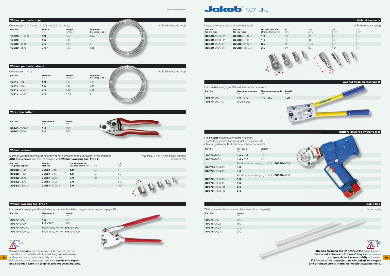
Webnet eye ends
Matches Webnet rope and Webnet strand AISI 316 material groupPart No.for one rope
Part No.for two ropes
For wire rope and stranded wire ø mm
bmm
ø dmm
hmm
kmm
30880-0100-02
30880-0150-02
30880-0200-02
30880-0300-02
30880-0100-01
30880-0150-01
30880-0200-01
30880-0300-01
1.0
1.5
2.0
3.0
13
16
20
27
2
3
4.5
5
5
8.3
10
14
2.5
3
3
5
Webnet swaging tool type 2
For on-site swaging of Webnet sleeves and eye endsPart No. Max. rope ø sleeves
mmMax. rope ø eye endsmm
Length mm
30570-2001 1.0 – 3.0 1.0 – 2.0 400
30570-2001-01 Tool inserts
Battery-powered swaging tool
For on-site swaging of Webnet eye ends.The battery-powered swaging tool is equipped with interchangeable tools; it can be purchased or rented.
Part No. For rope ø mm
Weight kg
30570-2004
30570-2003
1.0 – 1.5
1.0 – 3.0
1.6
4.2
Tool inserts for swaging tool No. 30570-2004
30570-0004-10 1.0
30570-0004-15 1.5
Tool inserts for swaging tool No. 30570-2003
30570-0003-10 1.0
30570-0003-15 1.5
30570-0003-20 2.0
30570-0003-30 3.0
Cable ties
Webnet assembly accessories (see example on page 49) Nylon whitePart No. Length
mm
30916-0001
30916-0002
30916-0003
30916-0004
120
160
270
330
On-site swaging and the choice of the correct rope or stranded-wire diameter with the matching Webnet sleeves
and eye ends are the responsibility of the user.Full functionality is guaranteed only with Jakob wire ropes
and stranded wire and original Webnet swaging tools.
Webnet perimeter rope
Construction 6 × 7 + core (* Ø 3 mm: 6 × 19 + core) AISI 316 material groupPart No. Rope ø
mmWeight kg/100 m
Minimum breaking load kN
10820-0100-42
10820-0150
10820-0200
10830-0300
1.0
1.5
2.0
3.0 *
0.41
0.88
1.57
3.60
0.5
1.4
2.4
5.8
Webnet perimeter strand
Construction 1 × 19 AISI 316 material groupPart No. Strand ø
mmWeight kg/100 m
Minimum breaking load kN
10810-0100
10810-0150
10810-0200
10810-0300
1.0
1.5
2.0
3.0
0.53
1.15
2.12
4.42
1.0
2.2
3.8
8.4
Wire-rope cutter
Part No. Max. rope ø mm
Length mm
30740-0500-0130740-0800
5.08.0
190500
Webnet sleeves
Matches Webnet perimeter rope and Webnet perimeter strand, available in two materialsAISI 316 sleeves can only be swaged with Webnet swaging tool type 2
Materials: E-CU Sn (tin-plated copper)and AISI 316
Part No.Tin-plated copper
Part No.AISI 316
For wire rope and stranded wire ø mm
bmm
ø dmm
30582-0100
30582-0150
30582-0200
30582-0300
30582-0300-01
30584-0100
30584-0150
30584-0200
30584-0300
30584-0300-01
1.0
1.5
2.0
3.0
3.0
7.3
7.3
10
11
11
4
5.7
7
8.3
10.7
Webnet swaging tool type 1
For on-site swaging of Webnet sleeves made of tin-plated copper (see example on page 49)Part No. Max. rope ø
mmLength mm
30570-1500
30570-20001.52.0 – 3.0
170260
30570-1500-01 Tool inserts for No. 30570-1500
30570-2000-02 Tool inserts for No. 30570-2000
On-site swaging and the choice of the correct rope or stranded-wire diameter with the matching Webnet sleeves and eye ends are the responsibility of the user.Full functionality is guaranteed only with Jakob wire ropes and stranded wire and original Webnet swaging tools.
Technical data subject to change
14
Battery-powered swaging tool
kN
Length mm
400400400
and the choice of the correct rope or stranded-wire diameter with the matching Webnet sleeves
and eye ends are the responsibility of the user.Full functionality is guaranteed only with Jakob wire ropes
On-site swaging and the choice of the correct rope or stranded-wire diameter with the matching Webnet sleeves
and eye ends are the responsibility of the user.
hød
b
k
b
ø d

40 41
41.1 41.2
Hexagon head cap screw M8
DIN 933 AISI 316 material groupPart No. c
mm
30843-0800-016
30843-0800-025
30843-0800
M8 × 16
M8 × 25
M8 × 40
Socket head screw M8
DIN 912 AISI 316 material groupPart No. c
mm
30844-0800-016
30844-0800-025
30844-0800
M8 × 16
M8 × 25
M8 × 35
M8 threaded rod
AISI 316 material groupPart No. c
mm
30882-0800 M8 × variable
Dual thread screw M8
With Phillips head AISI 316 material groupPart No. Length
mm
30990-0010
30878-0800
50
100
M8 nuts
AISI 316 material groupPart No. Type
30892-0800-02
30892-0800
30894-0800
DIN 985 lock nut
DIN 934 hexagon nut
DIN 1587 dome nut
M8 washers
AISI 316 material groupPart No. Type
30896-0800
30896-0800-24
ø d 15 mm, DIN 433
ø d 24 mm, DIN 9021 for wood
Wall anchor with internal thread RH M8
Suitable exclusively for concrete Galvanized steelPart No. Internal threads
30803-0800-02 M8
FIS VS 150 C injection mortar with perforated sleeve HK
For hollow and solid wallsPart No. Product
30803-0800-05
30803-0800-052
30803-0800-053
30803-0800-051
1 cartridge 145 ml with plunger disc, 2 mixer nozzles, 6 perforated sleeves HK
Mixer nozzle, separate
HK perforated sleeve, separate
Dispenser gun
FIS VS 150 C injection mortar is a 2-component resin mortar.The perforated sleeve is needed only for hollow masonry. The threaded rod can be glued directly into the hole of a concrete wall.
Rampa screw-in nut for wood RH M8
With hex socket, type SK, ~DIN 7965 Galvanized steelPart No. Internal threads
30803-0800-04 M8 Predrill hole in wood: ø 14.5 mm
Thread lock fl uid VC3
Protects screws and nuts against spontaneous looseningPart No.
30879-0001
The thread fl anks must be fi lled at least 2⁄3 of the way.
Thread lock fl uid VC3 is a lacquer-like coating that contains two separate, microencapsulated components.
The safety function is activated when the fl uid is compressed as the threaded fastener is closed. The
fastener is then protected against vibration; screws and nuts can no longer work themselves loose.
Illustration:Custom-made Webnet coupler for the fast disconnection of two nets
Technical data subject to change
c5,3 13
ø14,4M8
Predrill hole in wood: ø 14.5 mm
c8
ø13M8
c
M8
M8
8
M8
13
ø 14,4
6,5
8,5
M8
M8
13
ø 14,4
13
ø 14,4
15
2/3
50
M8
18
M8
18
30 / 6020 / 40
50 / 100
ø 8
ø dø d
ø M8ø M8
21,6
42.1
43.1
43.2
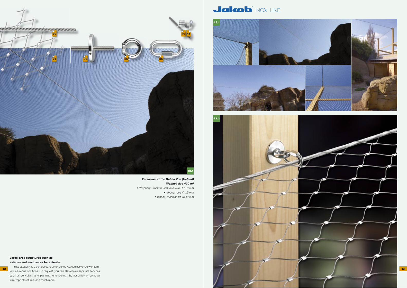
Large-area structures such as
aviaries and enclosures for animals.
In its capacity as a general contractor, Jakob AG can serve you with turn-
key, all-in-one solutions. On request, you can also obtain separate services
such as consulting and planning, engineering, the assembly of complex
wire-rope structures, and much more.
Enclosure at the Dublin Zoo (Ireland)
Webnet size 420 m²
• Periphery structure: stranded wire Ø 10.0 mm
• Webnet rope Ø 1.5 mm
• Webnet mesh aperture 40 mm
42 43
36363621
30 40 41
44.1
44.2
44.3
44.4
44.5
45.1
45.2 45.3
45.4
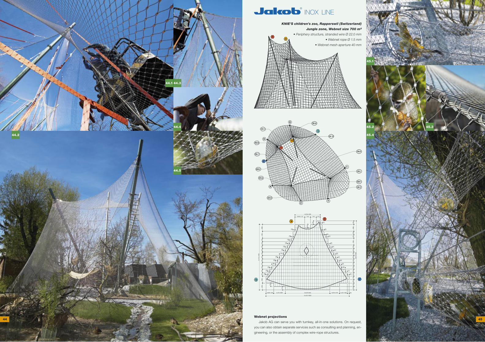
KNIE’S children’s zoo, Rapperswil (Switzerland)
Jungle zone, Webnet size 700 m²
• Periphery structure, stranded wire Ø 22.0 mm
• Webnet rope Ø 1.5 mm
• Webnet mesh aperture 40 mm
Webnet projections
Jakob AG can serve you with turnkey, all-in-one solutions. On request,
you can also obtain separate services such as consulting and planning, en-
gineering, or the assembly of complex wire-rope structures.
44 45
46.2
47.2
47.1
46.1
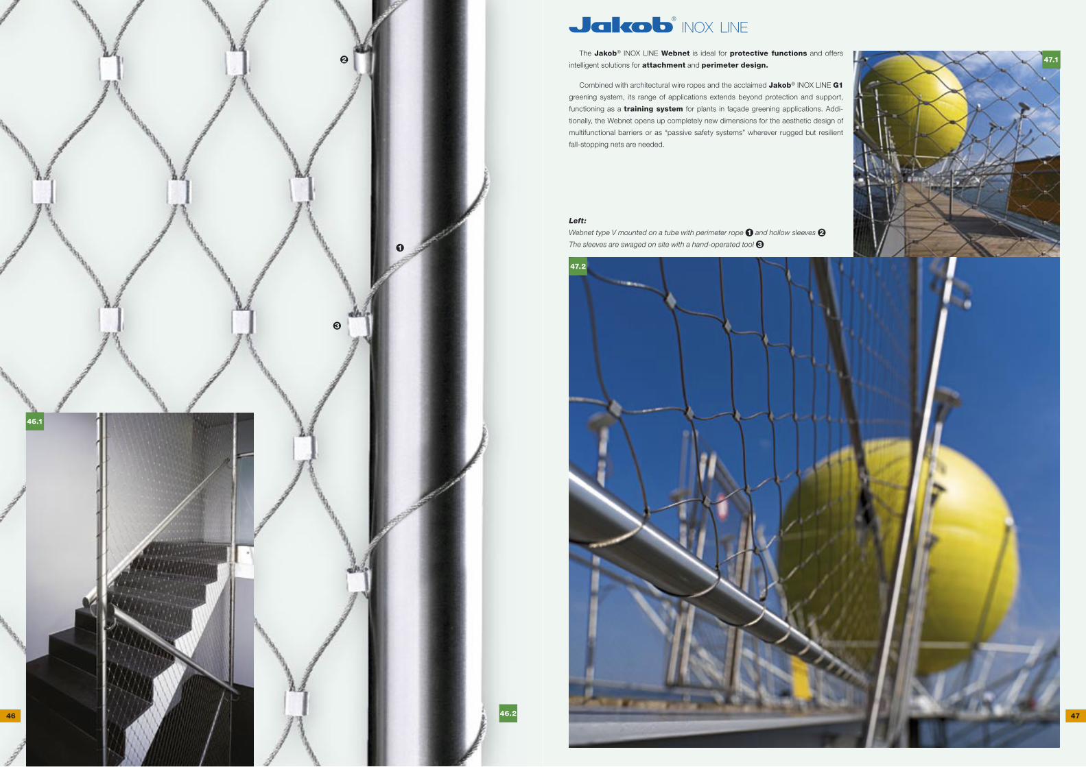
The Jakob® INOX LINE Webnet is ideal for protective functions and offers
intelligent solutions for attachment and perimeter design.
Combined with architectural wire ropes and the acclaimed Jakob® INOX LINE G1
greening system, its range of applications extends beyond protection and support,
functioning as a training system for plants in façade greening applications. Addi-
tionally, the Webnet opens up completely new dimensions for the aesthetic design of
multifunctional barriers or as “passive safety systems” wherever rugged but resilient
fall-stopping nets are needed.
Left:
Webnet type V mounted on a tube with perimeter rope 1 and hollow sleeves 2
The sleeves are swaged on site with a hand-operated tool 31
2
3
46 47
49.1
49.2
49.3
49.4
49.5
49.6
49.7
49.8
49.9
49.149.1
49.2
49.3
49.449.4
49.5
49.6
49.7
49.849.8
49.9
48.1
48.2
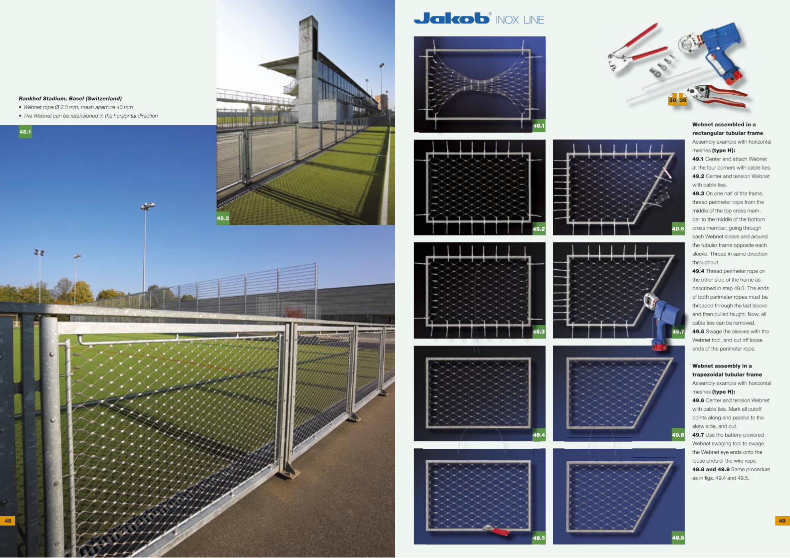
Webnet assembled in a
rectangular tubular frame
Assembly example with horizontal
meshes (type H):
49.1 Center and attach Webnet
at the four corners with cable ties.
49.2 Center and tension Webnet
with cable ties.
49.3 On one half of the frame,
thread perimeter rope from the
middle of the top cross mem-
ber to the middle of the bottom
cross member, going through
each Webnet sleeve and around
the tubular frame opposite each
sleeve. Thread in same direction
throughout.
49.4 Thread perimeter rope on
the other side of the frame as
described in step 49.3. The ends
of both perimeter ropes must be
threaded through the last sleeve
and then pulled taught. Now, all
cable ties can be removed.
49.5 Swage the sleeves with the
Webnet tool, and cut off loose
ends of the perimeter rope.
Webnet assembly in a
trapezoidal tubular frame
Assembly example with horizontal
meshes (type H):
49.6 Center and tension Webnet
with cable ties. Mark all cutoff
points along and parallel to the
skew side, and cut.
49.7 Use the battery-powered
Webnet swaging tool to swage
the Webnet eye ends onto the
loose ends of the wire rope.
49.8 and 49.9 Same procedure
as in fi gs. 49.4 and 49.5.
Rankhof Stadium, Basel (Switzerland)
• Webnet rope Ø 2.0 mm, mesh aperture 40 mm
• The Webnet can be retensioned in the horizontal direction
48 49
38 39
50.2
51.2
51.1
51.3
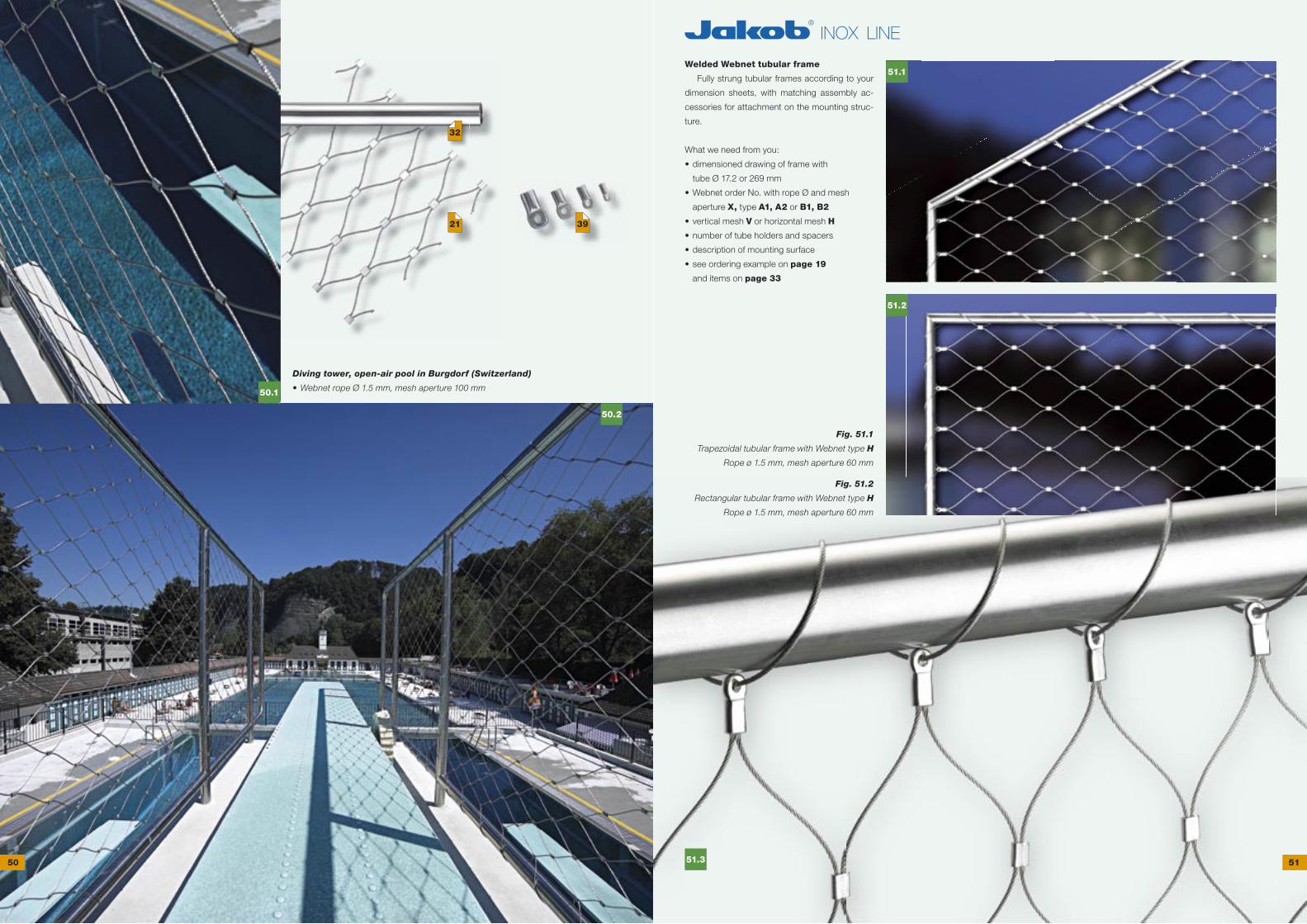
Welded Webnet tubular frame
Fully strung tubular frames according to your
dimension sheets, with matching assembly ac-
cessories for attachment on the mounting struc-
ture.
What we need from you:
• dimensioned drawing of frame with
tube Ø 17.2 or 269 mm
• Webnet order No. with rope Ø and mesh
aperture X, type A1, A2 or B1, B2
• vertical mesh V or horizontal mesh H
• number of tube holders and spacers
• description of mounting surface
• see ordering example on page 19
and items on page 33
Fig. 51.1
Trapezoidal tubular frame with Webnet type H
Rope ø 1.5 mm, mesh aperture 60 mm
Fig. 51.2
Rectangular tubular frame with Webnet type H
Rope ø 1.5 mm, mesh aperture 60 mm
Diving tower, open-air pool in Burgdorf (Switzerland)
• Webnet rope Ø 1.5 mm, mesh aperture 100 mm
50 51
32
50.1
21 39
53.1
53.2
52.1
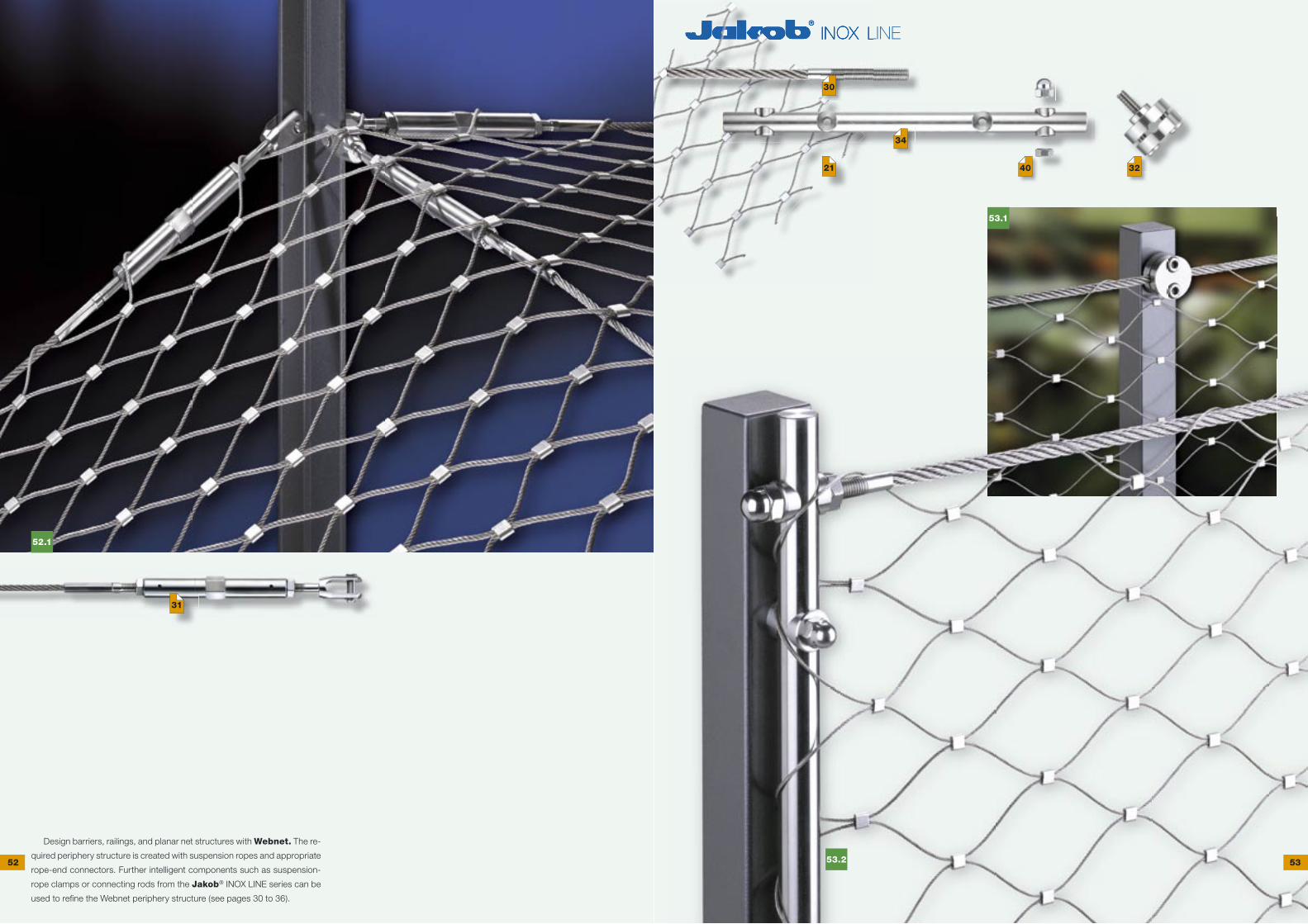
Design barriers, railings, and planar net structures with Webnet. The re-
quired periphery structure is created with suspension ropes and appropriate
rope-end connectors. Further intelligent components such as suspension-
rope clamps or connecting rods from the Jakob® INOX LINE series can be
used to refi ne the Webnet periphery structure (see pages 30 to 36).
52 53
30
40 32
34
31
21

55.1
54.2
54.1
54.3The Jakob® INOX LINE Webnet is ideal for ele-
gant protective nets and offers intelligent solutions
for attachment and perimeter design.
Deutsches Museum, Transportation Center
Munich (Germany)
• Suspension rope Ø 8.0 mm
• Webnet rope Ø 1.5 mm, mesh aperture 60 mm
54 55
56.1
57.1
57.2 57.3
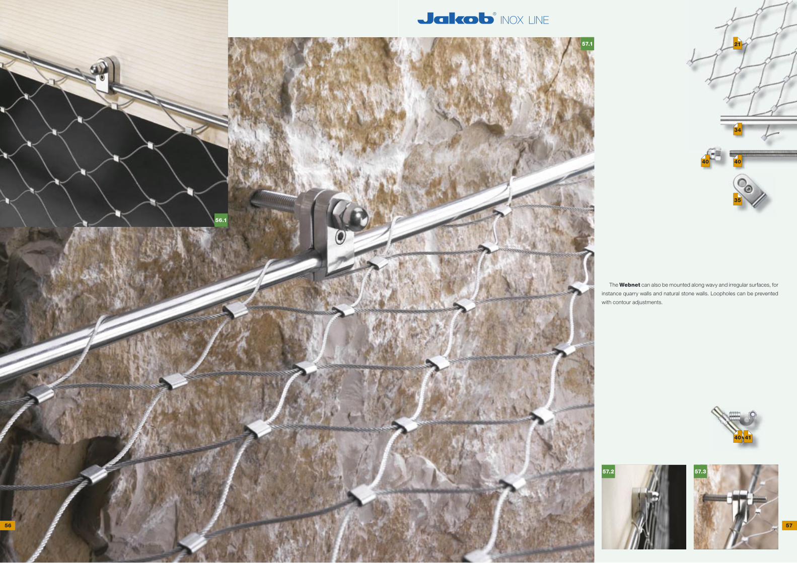
The Webnet can also be mounted along wavy and irregular surfaces, for
instance quarry walls and natural stone walls. Loopholes can be prevented
with contour adjustments.
56 57
34
40
40 41
40
21
35

58.1 59.2
59.1The Jakob® INOX LINE Webnet was tested pursuant to
EN 1263-1 for its static and dynamic load-bearing capacity.
Test data:
• Webnet size: length 7 m × width 5 m
• Webnet rope Ø 3.0 mm, mesh aperture 60 and 100 mm
(horizontal and vertical meshes)
• Webnet rope Ø 2.0 mm, mesh aperture 60 and 100 mm
(horizontal and vertical meshes)
• suspension rope Ø 10.0 mm
• test object: 500-mm steel sphere, mass 100 kg
• drop height of test object: 7 m
Historic city wall, Münsterplattform, Bern (Switzerland)
Safety net as a discreet passive safety system
58 59

61.2
61.4
61.3
61.1
60.1
60.2
60.3
60.4
60.5
The Jakob® INOX LINE rod system in
combination with Webnet sections offers a
vast spectrum of confi guration options that
fulfi ll both technical and design requirements
(see pages 34/35).
Wooden bridge Sachseln–Kerns
(Switzerland)
Safety net as a passive safety system
• Highest bridge of this type in Europe,
120 m above water level
• Suspension rope Ø 16.0 mm
• Webnet rope Ø 3.0 mm,
mesh aperture 100 mm
60 61
34
41
35
21
34
41
35
21

62.1
63.1
63.2
The Jakob® INOX LINE
rod system in combination with
Webnet sections offers a vast
spectrum of configuration options
that fulfill both technical and design
requirements (see pages 34/35).
35
35
35
62 63
40 41
34
34
34
40
21

64.1
64.2 64.3
64.4
64.5
64.6
65.1
The Jakob® INOX LINE C rail system allows flush mounting of Webnet
sections to structural surfaces. Four different C rail types are available for
assembly on different kinds of substrates.
Combined with the Jakob® INOX LINE rod system, these rails allow the
development of new and creative solutions with many confi guration options
(see pages 34 to 37).
64 65
34
21
21
37
35
66.1
66.2
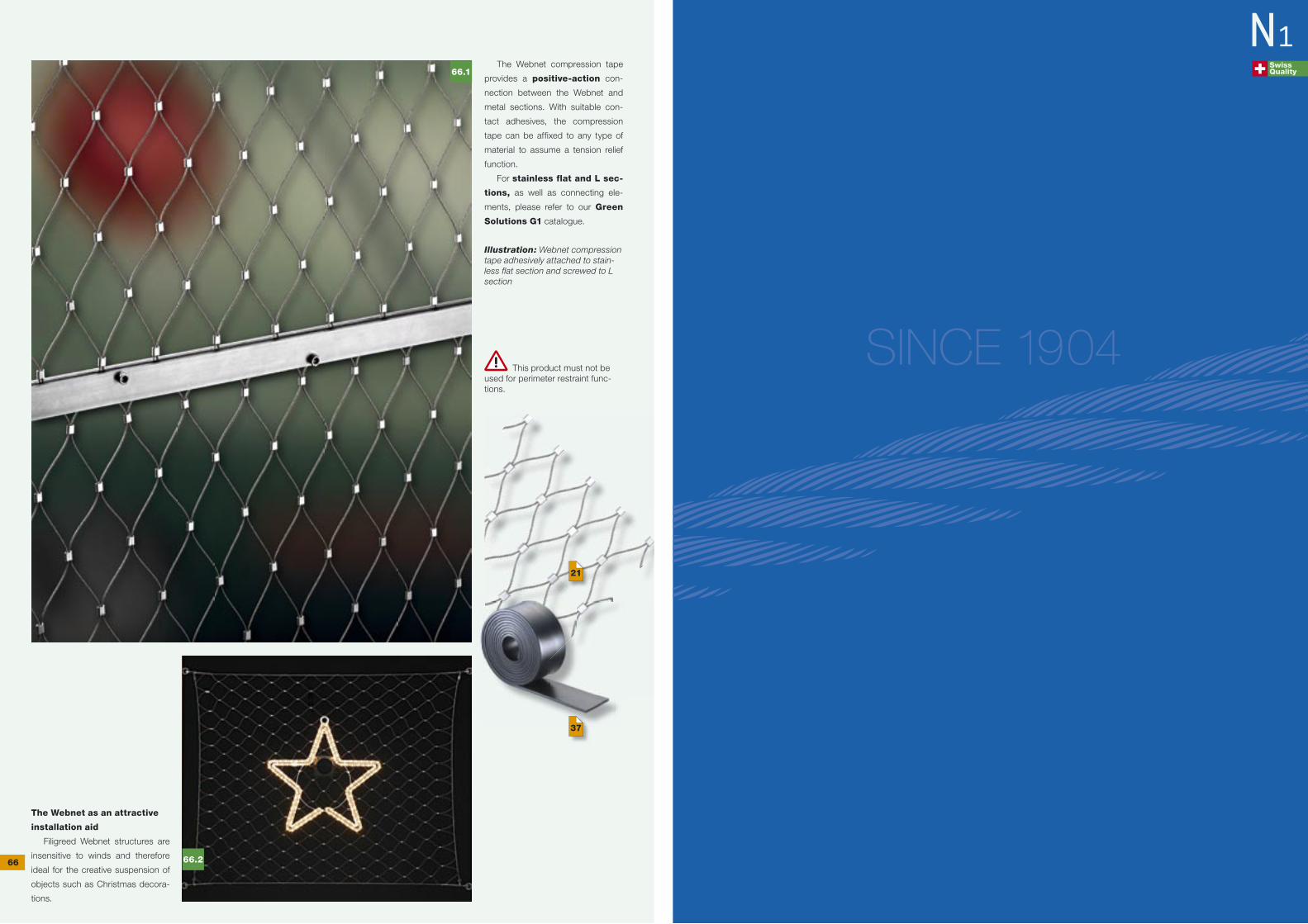
The Webnet compression tape
provides a positive-action con-
nection between the Webnet and
metal sections. With suitable con-
tact adhesives, the compression
tape can be affixed to any type of
material to assume a tension relief
function.
For stainless flat and L sec-
tions, as well as connecting ele-
ments, please refer to our Green
Solutions G1 catalogue.
Illustration: Webnet compression tape adhesively attached to stain-less flat section and screwed to L section
The Webnet as an attractive
installation aid
Filigreed Webnet structures are
insensitive to winds and therefore
ideal for the creative suspension of
objects such as Christmas decora-
tions.
This product must not be used for perimeter restraint func-tions.
SINCE 1904
Swiss Quality
N1
66
21
37