EMISSION CONTROL SYSTEMS -
28
25-1 EMISSION CONTROL SYSTEMS CONTENTS CRANKCASE EMISSION CONTROL SYSTEM . . . .. .. . .. . . .. . .. .. . . .. . .. . .. .. . . .. . .. .. . . .. . .. .. .. . . .._...._... Components Location . .. . . .. . .. .. . .. . . .. .. . ..._.._......_ Positive Crankcase Ventilation (PCV) Valve .._.....,................_.....__..._..._................_.._._.__.. EVAPORATIVE EMISSION CONTROL SYSTEM .. . .. . .. . . .. .. . . .. .. . . .. .. . . .. . .. .. . .. . . .. .. . .. . .. . .. .. .._... Components Location . . .. . . .. .. . .. _ . .. .. .. . . .. . .. . .. .. . .. Overfill Limiter (Two-way Valve) . .. .. . . .. . .. .. . .. . .. Purge Control System . . .. . .. . .. .. . . .. . .. .. . . .. . .. .. .. . . .. Purge Control Valve . . .. . . .. .. . .. . .. . .. .. .. .. .. . .. ..‘....... Therm0 Valve . . .. . .. . .. . .. . .. . .. . .. . .. . .. . .. . .. . .. .. . . .. . .. .. . .. . EXHAUST EMISSION CONTROL SYSTEM .. . Air-Fuel Ratio Control (ECI) System .. . .. .. . . . . . Components Location .. . .. ..._.......................... EGR Control Solenoid Valve .. . .. . . .. .. . .. . . .. .. .. . . .. . . EGR Valve . . .. .. . . .. . .. . .. . .. .. . . . .. .. . .. . .. . .. . . .. .. . .. . .. . .. . ..._.._ Engine Coolant Temperature Sensor and Idle Switch . .. .. . . .. . .. . . .. .. . .. . . .. .. . .. . .. . .. .. . . .. .. . . .. Exhaust Gas Recirculation (EGR) System . . .. .. . . .. .. . . .. . .. .. . . .. . .. . .. . .. . .. . .. . .. .. . . .. . .. .. . . .. .. . .. . Reed Va Ive . . .. . .. . .. . . . . .. .. . . .. .. .. . . . . .. . . . . . . . . . Secondary Air Cleaner .. . . .. .. . .. . . .. .. .. . . .. . .. .. . .. . .. . . Secondary Air Control Solenoid Valve .._......_.. Secondary Air Supply System . . .. . . . . . . . . .. . . . . Three-way Catalytic Converter . . . .. . . . .. . .. .. . .. . . 17 17 17 18 18 21 19 20 20 22 24 22 28 27 27 27 25 25 26 24 24 GENERAL INFORMATION .. .. . .. . .. . .. . .. . .. . .. .. . .. .. 2 Crankcase Emission Control System .. .._........... 4 ECI System Diagram . ..._............................_.......... 3 ~~ Evaporative Emission Control System .. . .. .. . . .. .. .. . 5 Exhaust Emission Control System . . . . .. .. .. . 6 SPECIFICATIONS .. . . .. .. .. . .. . .. . . . .. . .. . . . . .. .. .. .. . 12 General Specifications _....._.._._........_.._............ 12 Service Specifications _.._................................ 12 Torque Specifications _.._.._....__._....._................... 12 TROUBLESHOOTING . .. . .. .. . .. . .. . .. . .._................... 13 Emission Control Device Engine Hesitates or Poor Acceleration Engine will not Start or is Hard to Start (Cranking possible) Poor Fuel Mileage Rough Idle or Engine Stalls VACUUM HOSES . .. . . .. . .. .. .. . . .. . .. .. .. . . .. .. . .. .. . .. .. . . .. .. . 14 Vacuum Hoses Diagram .. . .. . .. . .. .. . .. . .. . .. .. . .. . .. .. . .. . 14
Transcript of EMISSION CONTROL SYSTEMS -
25-1
EMISSION CONTROL SYSTEMS
CONTENTS
CRANKCASE EMISSION CONTROL SYSTEM . . . . . . . . . . . . . . . . . . . . . . . . . . . . . . . . . . . . . . . . . . . . . . . . . . . . . .._...._...
Components Location . . . . . . . . . . . . . . . . . . . . . . . .._.._......_ Positive Crankcase Ventilation (PCV) Valve .._.....,................_.....__..._..._................_.._._.__..
EVAPORATIVE EMISSION CONTROL SYSTEM . . . . . . . . . . . . . . . . . . . . . . . . . . . . . . . . . . . . . . . . . . . . . . . . . . . . . . . .._...
Components Location . . . . . . . . . . . . . _ . . . . . . . . . . . . . . . . . . . . . .
Overfill Limiter (Two-way Valve) . . . . . . . . . . . . . . . . . . . . Purge Control System . . . . . . . . . . . . . . . . . . . . . . . . . . . . . . . . . . . . Purge Control Valve . . . . . . . . . . . . . . . . . . . . . . . . . . . . . . ..‘.......
Therm0 Valve . . . . . . . . . . . . . . . . . . . . . . . . . . . . . . . . . . . . . . . . . . . . . . . . . . . .
EXHAUST EMISSION CONTROL SYSTEM . . . Air-Fuel Ratio Control (ECI) System . . . . . . . . . . . . Components Location . . . . . . .._.......................... EGR Control Solenoid Valve . . . . . . . . . . . . . . . . . . . . . . . . . . . . EGR Valve . . . . . . . . . . . . . . . . . . . . . . . . . . . . . . . . . . . . . . . . . . . . . . . . . . . . . . .._.._ Engine Coolant Temperature Sensor and Idle Switch . . . . . . . . . . . . . . . . . . . . . . . . . . . . . . . . . . . . . . . . . . . . . . . .
Exhaust Gas Recirculation (EGR) System . . . . . . . . . . . . . . . . . . . . . . . . . . . . . . . . . . . . . . . . . . . . . . . . . . . . . . . . . . . . . . . . Reed Va Ive . . . . . . . . . . . . . . . . . . . . . . . . . . . . . . . . . . . . . . . . .
Secondary Air Cleaner . . . . . . . . . . . . . . . . . . . . . . . . . . . . . . . . . . . . Secondary Air Control Solenoid Valve .._......_..
Secondary Air Supply System . . . . . . . . . . . . . . . . . . Three-way Catalytic Converter . . . . . . . . . . . . . . . . . . . .
17
17
17
18 18
21 19 20
20
22 24 22 28 27
27
27 25 25 26 24 24
GENERAL INFORMATION . . . . . . . . . . . . . . . . . . . . . . . . . . . . . 2
Crankcase Emission Control System . . .._........... 4
ECI System Diagram . . .._............................_.......... 3 ~~
Evaporative Emission Control System . . . . . . . . . . . . . . . . 5 Exhaust Emission Control System . . . . . . . . . . . 6
SPECIFICATIONS . . . . . . . . . . . . . . . . . . . . . . . . . . . . . . . . . . . . . 12 General Specifications _....._.._._........_.._............ 12 Service Specifications _.._................................ 12
Torque Specifications _.._.._....__._....._................... 12
TROUBLESHOOTING . . . . . . . . . . . . . . . . . . .._................... 13 Emission Control Device Engine Hesitates or Poor Acceleration Engine will not Start or is Hard to Start (Cranking possible) Poor Fuel Mileage
Rough Idle or Engine Stalls
VACUUM HOSES . . . . . . . . . . . . . . . . . . . . . . . . . . . . . . . . . . . . . . . . . . . . . . . . 14
Vacuum Hoses Diagram . . . . . . . . . . . . . . . . . . . . . . . . . . . . . . . . . . . . 14
q;i .i . , ~ [’ ; I j- p / 11
: i j. ___A’-__--- A - f ___~. - -- ,** -=
25-2 EMISSION CONTROL SYSTEMS - General Information g +
GENERAL INFORMATION m- c:-
N25BEBAa !eF+
The emission control system has the following three major %ystems. Es -
(I) Crankcase emlsslon control system @s (2) Evaporative emission control system Egg-- (3) Exhaust emission control system &&
The crankcase emrsslon control system IS a system adopting a c,losed-type crankcase ventilation to prevent ~~ S Es-
blow-by gas from escaping into the atmosphere. The generated-gas IS Instead-led to the combustion chamber s r for combustion,- gg+
The evaporative emlsslon control system tor preventtng loss ot tuel vapor trom the tuel system to the mu_ gE== Et&
.-rttnosphere consists of various components (a cantster, purge control valve, two-way valve and so on) which II
I~l~)llect and lead venerated fuel vapor to the combustion chamber for combustton. EiG
The exhaust emlsslon control system consists ot an air-tuel ratio control system (tCi system), three-way Z gp
I:.rltalytic converter, exhaust gas recrrculatlon system, secondary atr supply system and so on to reduce t!nllsstutIs ut CO. HC and NOx.
Eel: Electronicallv Controlled lnlectlon !g SPY
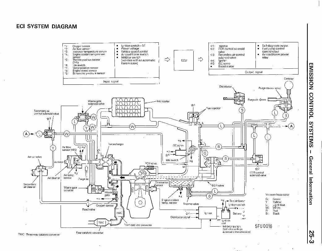
ECI SYSTEM DIAGRAM
‘1: Oxygen sensor l Ignition switch-ST “2: Air flow sensor 0 Power voltage
:;- Intake atr temperature sensor l Vehicle speed sensor Enginecoolant temperature l Air conditioner swttch sensor l Inhibitor switch
l 5. ~Ti;tle positton sensor (vehicles with an automatic
‘6. Idle switch transm’ssion)
“7: Motor position sensor ‘8. Engine speed sensor l 9 Barometric pressure sensor
Input signal
c3 q ECU c3 ~
Output s’gnal
Cantster
Dtstrtbutor
I Purge control valve
\ w
Intercooler
Secondary atr control solenotd valve
/Fuel infector
Atr cut valve II I Ihn
Vacuum hose color
G: Green Y: Yellow
Purge atr e
F+il
I( --- I;---&-Jl ‘EGR valve
Reed valve
COII
InhIbItorswitch (Vehtcles wtth an
5FUOO16
TWC Three-way catalyttc converter Rear catalyttc converter automattc transmtsson)
-
25-4 EMISSION CONTROL SYSTEMS - General Information
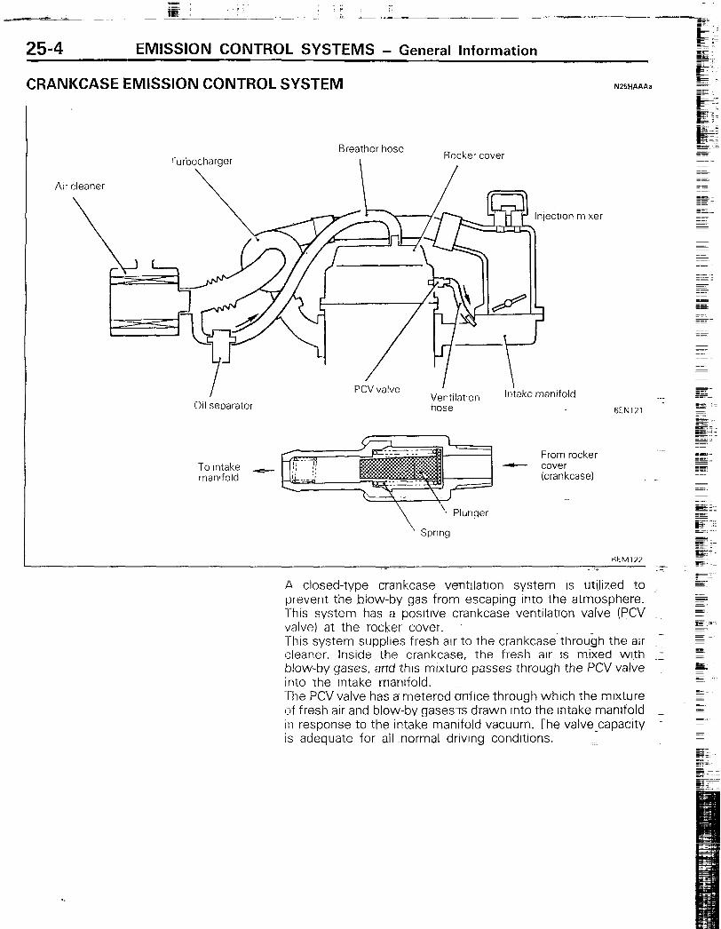
CRANKCASE EMISSION CONTROL SYSTEM N25HAAAa
Breather hose Rocker cover
Air cleaner
011 separator Ventilzition hose
intake manifold 6EN121
To Intake + manifold
From rocker - cover
(crankcase)
.-.
\ Spring
A closed-type crankcase ventllatlon system is utilized to ._ prevent the blow-by gas trom_escaping Inro~ the atmosphere. This system has-a positive crankcase ventilatron valve (PCV ~. valve) at the rocker cover. This system supplies fresh air to the crankcase throubh the air Ed cleaner. lnsrde the crankcase, the tresh air is mixed with .I blow-by gases, arcd this mixture passes through the PCV valve Into the intake manifold. The PCV valve has a metered &fice through which the mixture l:~f fresh air and blow-by gases~Ts drawn into the intake manifold -1 In response to the intake manltold vacuum. Ihe valve.capacity IS adequate for all -normal driving conditions.
EMISSION CONTROL SYSTEMS - General Information 25-5
EVAPORATIVE EMISSION CONTROL SYSTEM NZBHBAB
urge control valve
Overfilllimiter (Two-way valve)
Fuel vapor 17.-Purge air
03uoo45
To purge control vale
Charcoal -
To injection mixer t
To injection -) mixer
9 To air intake hose
0 from canister EC11 19
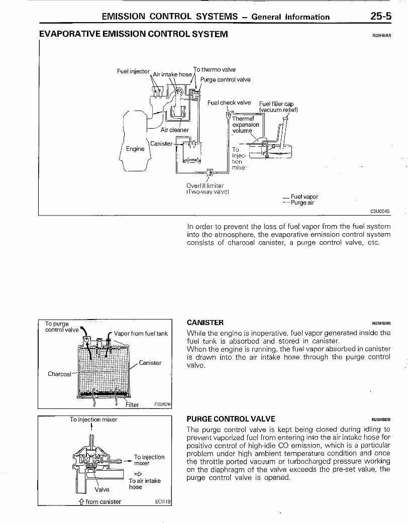
In order to prevent the loss of fuel vapor from the fuel system into the atmosphere, the evaporative emission control system consists of charcoal canister, a purge control valve, etc.
CANISTER NZlHBBB
While the engine is inoperative, fuel vapor generated inside the fuel tank is absorbed and stored in canister. When the engine is running, the fuel vapor absorbed in canister is drawn into the air intake hose through the purge control valve.
PURGE CONTROL VALVE N25HBDB
The purge control valve is kept being closed during idling to prevent vaporized fuel from entering into the air intake hose for positive control of high-idle CO emission, which is a particular problem under high ambient temperature condition and once the throttle ported vacuum or turbocharged’ pressure working on the diaphragm of the valve exceeds the preset value, the purge control valve is opened.
.-II _
25-6
.‘I?. c ; -A.-
EMISSION CONTROL SYSTEMS - General information
To purge control valve
Injection mixer
Thermo sensor GEMOK
) To overflll limiter
From fuel tank WE5 1 I
?ellef valve
/c-r==?
F
ket
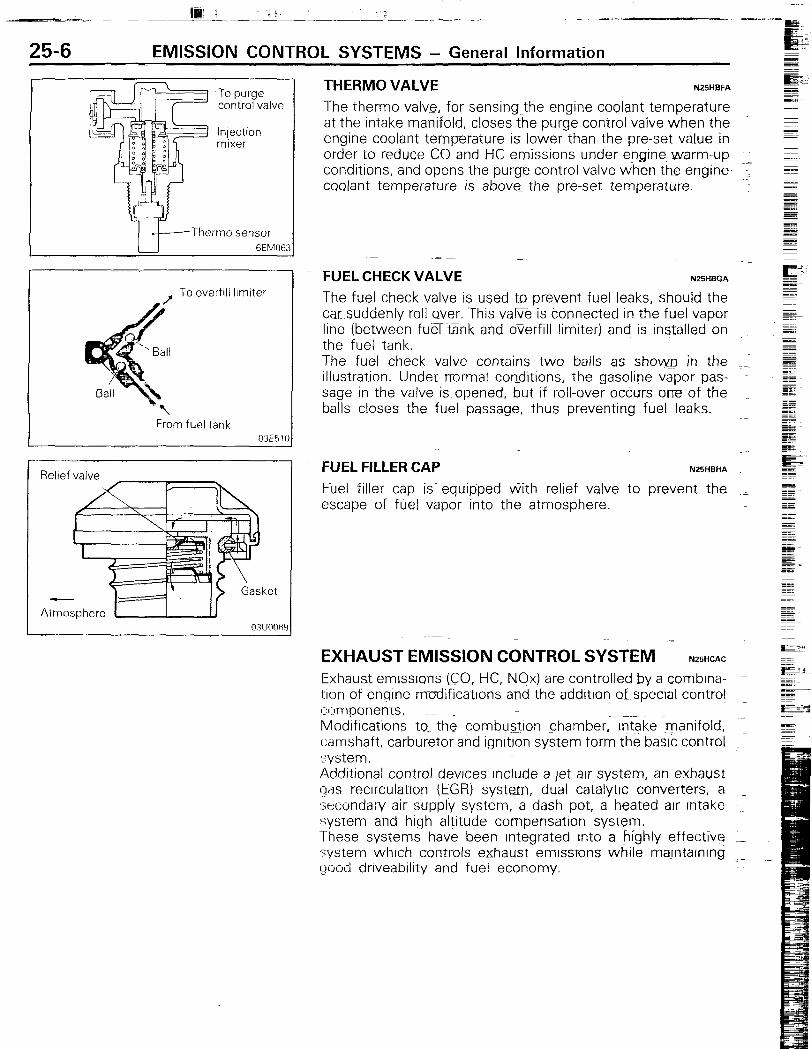
THERM0 VALVE NZlHBFA
The therm0 valve, for sensing the engine coolant temperature at the intake manifold, closes the purge control valve when the - engine coolant temperature is lower than the pre-set value in mm order to reduce G!!and HC e_missions under eggine~warm-up I, conditions, and opens the purge control valve when the engine ~ coolant temperature is above_ the pre-set temperature.
-
FUEL CHECK VALVE N25HBGA
The fuel check valve is used to prevent fuel leaks, should the car suddenly roll over. This~vaEe is connected in the fuel vapor line (between fua tank and oyerfill limiter) and is insTalled on the fuel tank. The fuel check valve contains two balls as show.0 in the .I illustration. Under normal conditions, the gasoline vapor pas- sage in the valve is opened, but if roll-over occurs one of the I balls closes the fuel passage, thus preventing fuel leaks.
FUEL FILLER CAP N25HBHA
Fuel filler cap is~ equipped tiith relief valve to prevent the _ escape of fuel vapor into the atmosphere.
= EXHAUST EMISSION CONTROL SYSTEM N25HCAC
Exhaust emlsslorrs (CO, HC, NJx) are controlled by a combrna- ~~ tlon ot engine mudificatlons and the addition at special control 02mponents. ~_ Modifications to.. the combu&on chamber. Intake manifold, ; camshatt, carburetor and ignltron system torm the basic control system. AddItional control devices include a jet air system, an exhaust qas recrrculatlon (tGR) system, dual catalytic converters, a secondary ait- supply system,-a dash pot, a heated atr intake I system and hig h altitude compensation system. These systems -have been Integrated Into a highly effective L system whrch controls exhaust emlssrons while majntaining - good dnveability and fuel economy.
EMISSION CONTROL SYSTEMS - General Information 25-7
Exhaust -
-I l- 3EM097
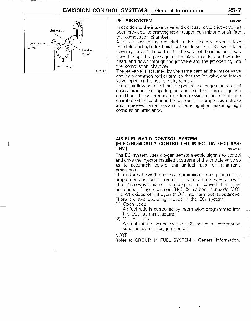
JET AIR SYSTEM NZIHCBB
In addition to the intake valve and exhaust valve, a jet valve has been provided for drawing jet air (super lean mixture or air) into the combustion chamber. A jet air passage is provided in the injection mixer, intake manifold and cylinder head. Jet air flows through two intake : openings provided near the throttle valve of the injection mixer, goes through the passage in the intake manifold and cylinder head, and flows through the jet valve and the jet opening into ’ the combustion chamber. The jet valve is actuated by the same cam as the intake valve and by a common rocker arm so that the jet valve and intake valve open and close simultaneously. The jet air flowing out of the jet opening scavenges the residual gases around the spark plug and creates a good ignition ~~ condition. It also produces a strong swirl in the combustion I chamber which continues throughout the compression stroke and improves flame propagation after ignition, assuring high _ combustion efficiency.
AIR-FUEL RATIO CONTROL SYSTEM [ELECTRONICALLY CONTROLLED INJECTION (ECI) SYS- TEM] N25HCCBa
The ECI system uses oxygen sensor electric signals to control ~~ and drive the injector installed upstream of the throttle valve so as to accurately control the air-fuel ratio for minimizing emissions. This in turn allows the engine to produce exhaust gases of the proper composition to permit the use of a three-way catalyst. The three-way catalyst is designed to convert the three pollutants (1) hydrocarbons (HC), (2) carbon monoxide (CO), and (3) oxides of Nitrogen (NOx) into harmless substances. There are two operating modes in the ECI system: (1) Open ,Loop
Air-fuel ratio is controlled by information programmed into ~~ the ECU at manufacture.
(2) Closed Loop Air-fuel ratio is varied by the ECU based on information my supplied by the oxygen sensor.
NOTE Refer to GROUP 14 FUEL SYSTEM - General Information.
25-8 EMISSION CONTROL SYSTEMS - General Information
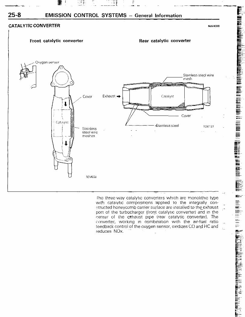
CATALYTIC CONVERTER
Front catalytic converter
NlBHCDB
Rear catalytic converter
Cover
Stainless steel wire meshes
5EM058
StaInless steel wire /-mesh
Exhaust 3
! StaInless steel lEM127 _ -
The three-way catalytic converters which are monollthlc type with catalytic composltions applied to the Integrally con- strutted honeycomb carrrer surface are rnstalled to the exhaust port of the turbocharger /trot-&catalytlc converter) and in the -! center of the exhaust pipe (rear catalytic converterj. The converter, working In combrnatlon with the air-fuel ratio ..= feedback control of the oxygensensor, oxrdlzes CO and HC and reduces NOx. ~~~

EMISSION CONTROL SYSTEMS - General Information 25-9
Stoichiometric ratio 01251:
SECONDARY AIR SUPPLY SYSTEM
Control relay
6--
Function The three-way catalytic converter removes CO, HC and NQx most effectively in the vicinity of the stoichiometric ratio. ’ The air-fuel ratio feedback control by’ the oxygen sensor controls the air-fuel mixture to the stoichiometric ratio and the catalytic converter promotes both oxidation and reduction of resultant exhaust gas to make it clean before it is released to atmosphere. Caution The catalytic converters require the use of unleaded gasoline only. Leaded gasoline will destroy the effective- ness of the catalysts as an emission control device. Under normal operating conditions, the catalytic convert- ers will not require maintenance. However, it is important to keep the engine properly tuned. If the engine is not kept properly tuned, engine misfiring may cause overheating of the catalysts. This may cause heat damage to the convert- ers or vehicle components. This situation can also occur during diagnostic testing if any spark plug cables are removed and the engine is allowed to idle for a prolonged period of time.
Fuel injector 1
-1 Secondary air control solenoid /
Secondary air cleaner
Oxygen s”e;;gor
ISC motor
+@
F ECU
Ii 1
perature sensor
II’ Ignition coil
Air flow sensor TWC: Three-way catalytic converter
5EM059
25-10 EMISSION CONTROL SYSTEMS - General Information
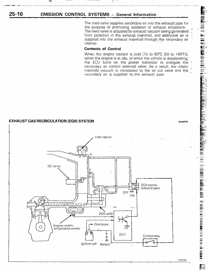
The reed valve supplies secondary air Into the exhaust pipe for _ the purpose oft promoting oxldatlon of exhaust emissions. __ The reed valve is actuated by exhaust vacuum being generated ~ _ from pulsation i17 the exhaust manifold, and additional air IS ~; supplied into the exhaust manitold through~ th_e secpndary air _ cleaner, - Contents of Control When the engirre coolant Is~:cold 115 to 63°C (59 to 145”F)l. when the engrnels at Idle, orwhen the vehlcie is decelerating, : the ECU turns own the power transistor to energize rhe ; secondary air cuntrol solenord valve. As a result, the Intake manifold vacuum is Introduced to the arr cut valve and the i: secondary air IS. supplied to_the exhaust pipe.
EX#AUST GAS RECIRCULATION (EGR) SYSTEM NZ5HCFB
/ Fuel injector
solenoid valve
I ~_ ~_ . ---_ --- - ----- ----_ , I
/”
EGR val% -
Y ECU
Engine coolant temperature sensor
kJlitiOtl Coil .‘. -
Bat&v
Control r&w
I I
I /* 1
EMISSION CONTROL SYSTEMS - General Information 25-11
Exhaust Gas Recirculation (EGR) system is designed to reduce oxides of nitrogen in the vehicle exhaust. In this system, the exhaust gas is partially recirculated from an exhaust port at the cylinder head into a port located at the intake manifold while the EGR flow is controlled by an EGR control valve, an EGR control solenoid valve, and an ECU. Contents of Control As the engine is warmed up and the engine coolant tempera- ture rises [to 55°C (131°F) or higher] but the engine speed is low (approximately 3,500 rpm or less), the ECU turns off the power transistor so as to shut off current flowing to the EGR ~- control solenoid valve. As a result, the mixing body E port vacuum acts on the EGR valve to open it. At this time, the EGR flow rate is controlled by the E port vacuum. Namely during idling or wide throttle valve opening operation when the E port vacuum is low, the EGR valve is closed by the spring force so that EGR gas does not flow. NOTE During idling, the EGR gas is shut off to ensure stable idling operation.

25-12 EMISSION CONTROL SYSTEMS - SDecifications
SPECIFICATIONS GENERAL SPECIFICATIONS
N25CA..
Po%ifive crZnkcase ventilation (PCVI valve
Canister Two-way valve Purge control valve
Air-fuel ratio control system - ECI TURBO system
Three-way catalytic converter
Secondaryair supply system Reed valve
Oxygen sensorfeedback type (Purpose: Control of CO, HC, NOx emission) Dual monolithictype (Front and Rear CCI (Purpose: Control of CO, HC. NOx-emission)
Secondary air control solenoid valve Secondary air cleaner
On-off solenoid valve
Exhaust gasrecirculation system EGR valve EGR control solenoid valve
SERVICE SPECIFICATIONS NZ5CB..
Items Specifications
Secon~dary airontrol solenoid valve coil resistance [at 20°C (68”FJI 0 EGRcontrol slolenoid valve coil resistance [at 20°C (68”FTl 0 Therm0 valve opening temperature “C (“F)
36 1~44
36-44 60 (I 40)
TORQUE SPECIFICATIONS N25CG.
Items
Secondary air pipe reed valve side joint Secondary air pipe exhaust manifold side joint EGR valve attaching bolt Therm0 valve
Nm ~~
50-Xl 70 - 100 7-11 20-40
ftlbs.
37-52 - 52-73 5-8 15-30
EMISSION CONTROL SYSTEMS - Troubleshooting 25-13
TROUBLESHOOTING NZEA- -a
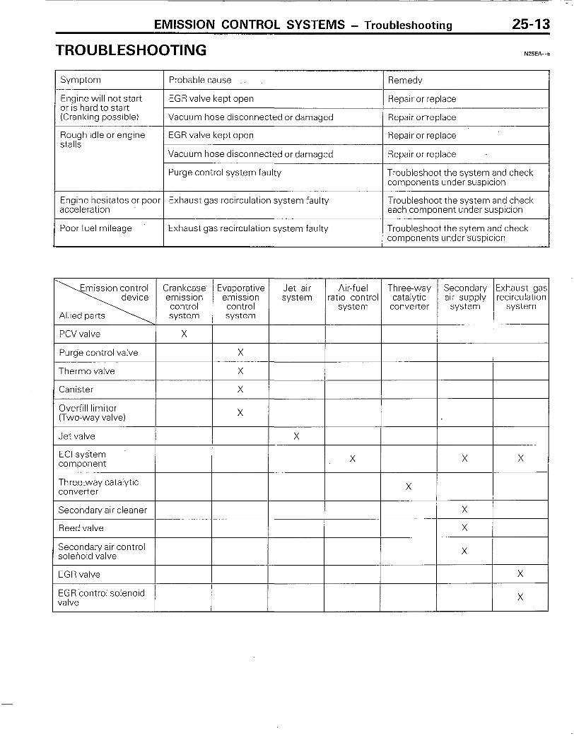
Symptom Probable cause Remedy
Engine will not start EGR valve kept open Repair or replace or is hard to start (Cranking possible) Vacuum hose disconnected or damaged Repair orreplace
Rough ~cfle or engine EGR valve kept open Repair or replace stalls
Vacuum hose disconnected or damaged Repair or replace
Purge control system faulty Troubleshoot the system and check components under suspicion
Engine hesitates or poor Exhaust gas recirculation system faulty Troubleshoot the system and check acceleration each component under suspicion
Poor fuel mileage Exhaust gas recirculation system faulty Troubleshoot the sytem and check components under suspicion
Secondary air cleaner
Reed valve
Secondary air control solenoid valve
EGR valve
EGR control solenoid valve
25-14 EMISSION CONTROL SYSTEMS - Vacuum Hoses
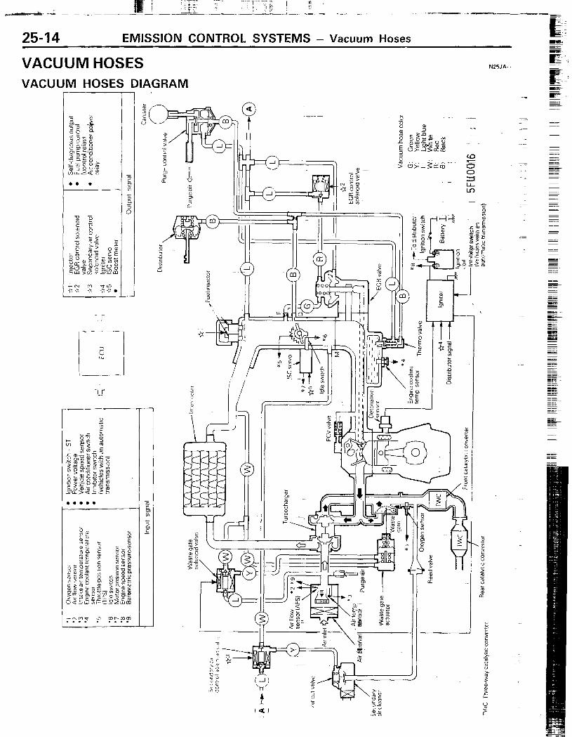
VACUUM HOSES VACUUM HOSES DIAGRAM
-1-r
N25JA..
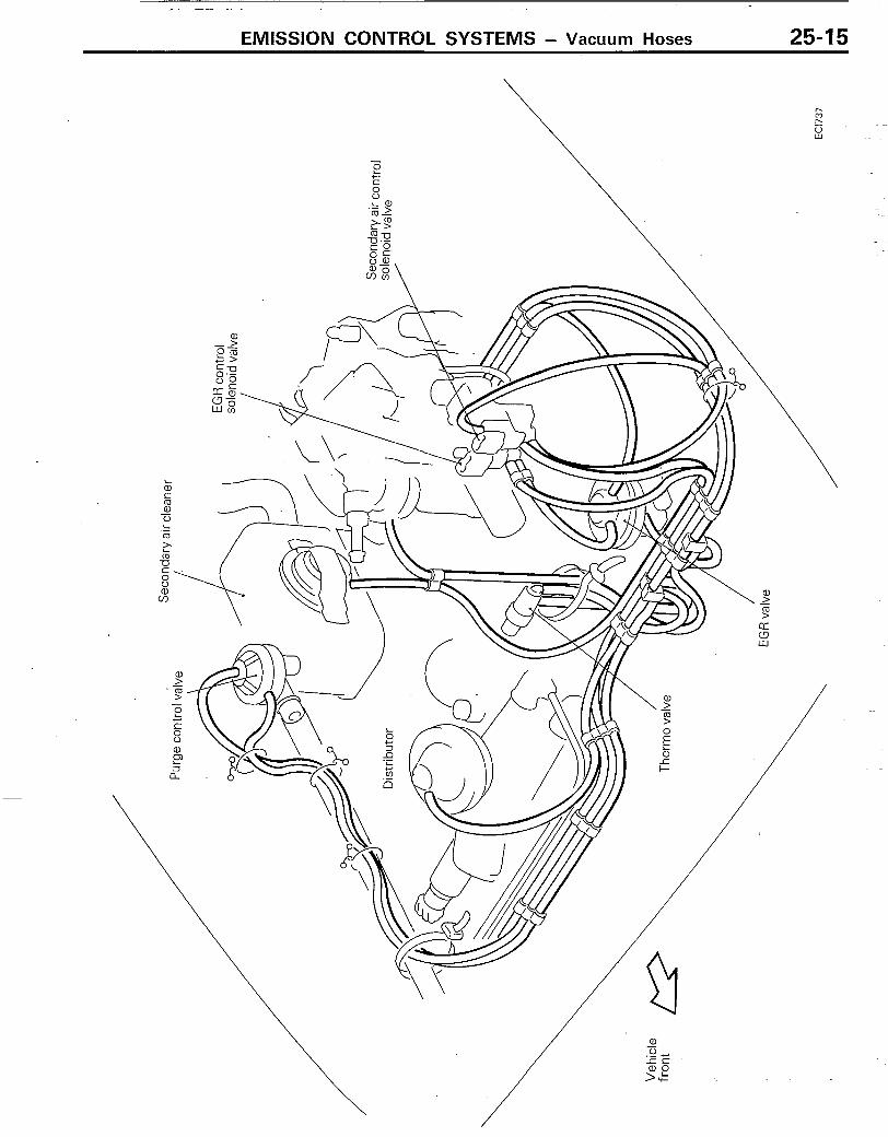
EMISSION CONTROL SYSTEMS - Vacuum Hoses 25-15
.’ m
25-16 EMISSION CONTROL SYSTEMS - Vacuum Hoses
INSPECTION N25JCAC
!‘I) Check that the vacuum hoses have been connected _ ~orrecrlv according to the vacuum hoses diagram.
(2) Check hose connectlon (dIsconnectIons, loose clamping, r”~c 1 and check tor bends, datnaqe and other abnormalities.
INSTALLATION N25JDAC
(I 1 When connectlnq a hose, connect securely to the nlpple. (2) Connect correctly reternnq to the vacuum hoses diagram
EMISSION CONTROL SYSTEMS - Crankcase Emission Control System ’ 2547
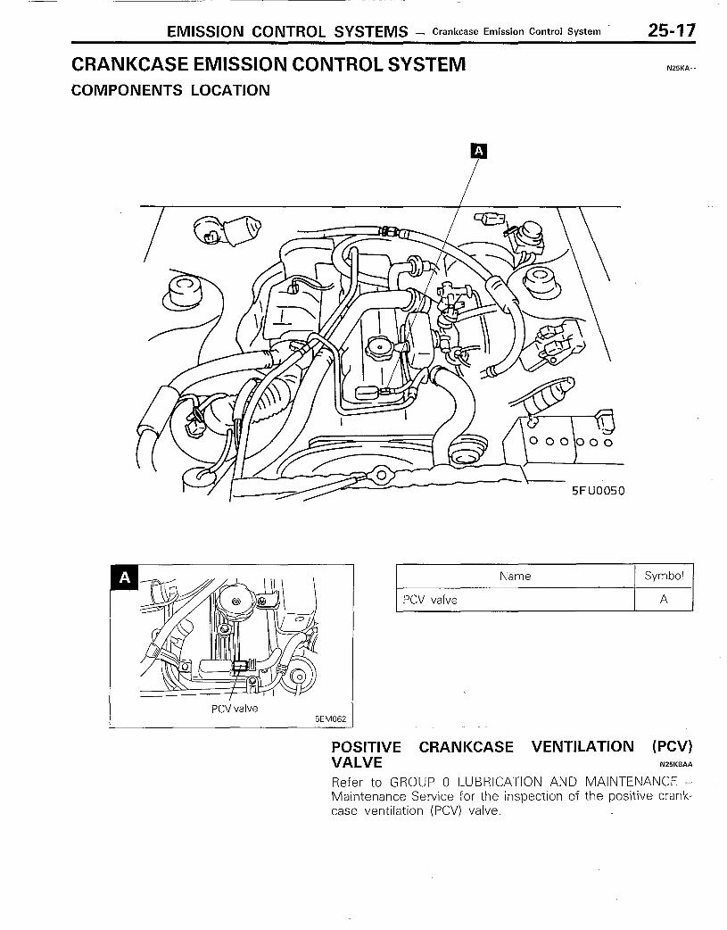
CRANKCASE EMISSION CONTROL SYSTEM N25KA- -
COMPONENTS LOCATION
PCV valve
Name Symbol
A
5EM062
POSITIVE CRANKCASE VENTILATION (PCV) VALVE N25KBAA
Refer to GROUP 0 LUBRICATION AND MAINTENANCE - Maintenance Service for the inspection of the positive crank- case ventilation (PCV) valve.
---,, .__
25-18
i ‘Ai T l-i- 1;. ip!- ~‘I~ _
EMISSION CONTROL SYSTEMS - EWporative Emisshn Control System
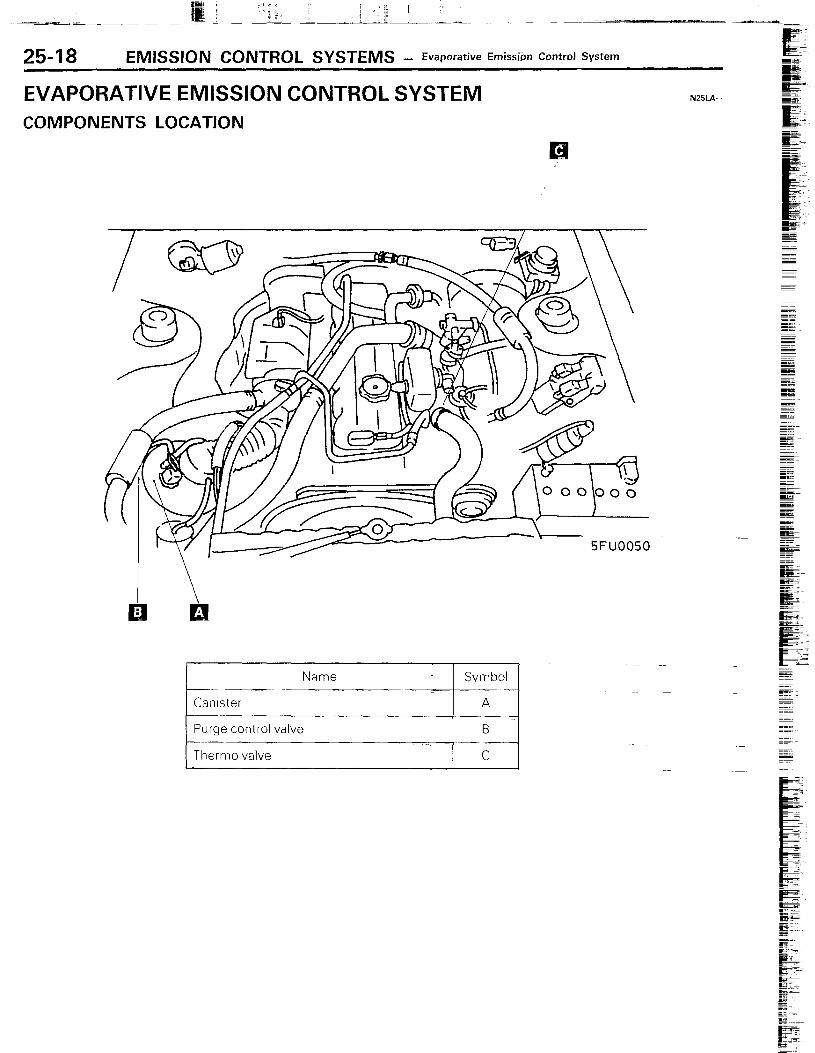
EVAPORATIVE EMISSION CONTROL SYSTEM N25i.A
COMPONENTS LOCATION
5FU0050
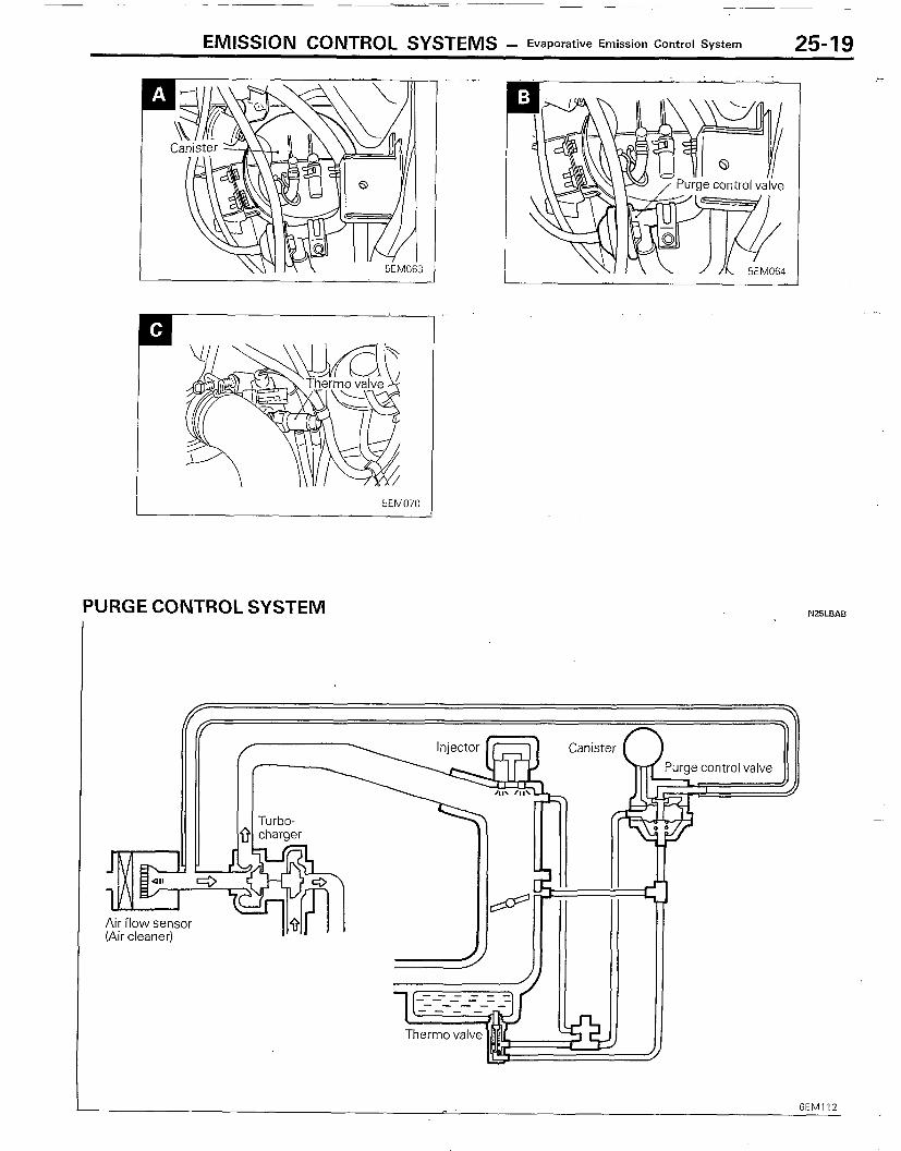
EMISSION CONTROL SYSTEMS - Evaporative Emission Control System 25-19
I 5EM070
PURGE CONTROL SYSTEM NZBLBAB
Air flow sensor (Air cleaner)
25-20 EMISSION CONTROL SYSTEMS 7 Evaporative Emissibn Control System -. __~~ I_ !!!!ex-
__.._ Valve
/ ll-n
Therm0 sensdr for engine coolant temperature detection
--
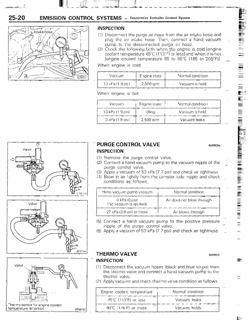
INSPECTION (1) Disconnect the purge air hose from the air intake hose and ~~ c
plug the air intake hose. Then, connect a hand vacuum : EE pump to the disconnected purge air hose.
(2) Check the following both whenthe engine is cold [engine coolant temperature 45°C (T13”F) or less] and whenjt is hot [engine coolant temperature 85 to 95C (185 to 205’F)I.
When engine is -cold
Vacuum
13 kPa (I .9 psi)
Engine state
2,500 rpm
Normal condition
Vacuum is held
When enqrne IS hot
PURGE CONTROL VALVE INSPECTION
N251ECBa
(1) Remove the purge control valve. (2) Connect a hand vacuum pump to the vacuum nipple of the
purge control valve. (3) Apply a vacuum of 53 kPa (7.7 PSI) and check air tightness. (4) Blow in air lightly from the canister side nipple and check
conditions as _follows.
(5) Connect a hand vacuum pump to the positive pressure ’ nipple of the purge control valve.
(6) Apply a vacuumm of 53 kPa (7.7 psi) and check air tightness. _
THERM0 VALVE INSPECTION
N25lFJDG ~_
(1) Disconnect the vacuum hoses (black and blue stripe) from the therm0 valve and connect a hand vacuum pump to the therm0 valve.
(2) Apply vacuum and check therm0 valve condition as follows.
Engine coolant temperature Normal condrtron
_ 45T (I 13°F) or less Vacuum leaks
80X (176’F) or more Vacuum holds
EMISSION CONTROL SYSTEMS - Evaporative Emission Control System 25-21
REMOVAL (I) When removing the therm0 valve, do not use wrenches or ~1
other tools on the resin part. (2) When disconnecting the vacuum hose, put a mark on the I-
hose so that it may be reconnected at original position.- ‘--
INSTALLATION (I) When installing, apply sealant (3M NUT Locking No. 4171 ~.
or equivalent) to the threads and tighten to 20 to 40 Nm (15--- ‘= to 30 ft.lbs.).
(2) When installing the therm0 valve, do not use wrenches or other tools on the resin part.
OVERFILL LIMITER (TWO-WAY VALVE) N25lBEB
Refer to GROUP 14 FUEL SYSTEM - Fuel Tank for the inspection of the overfill limiter (two-way ~valve).
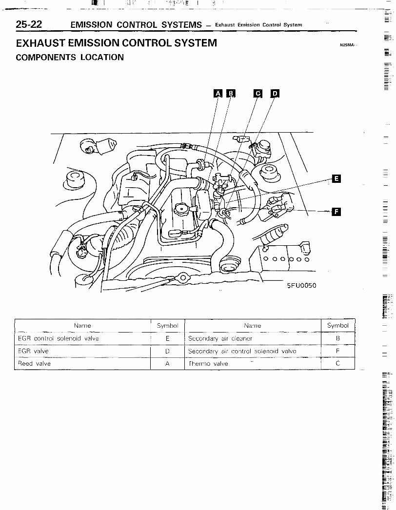
EXHAUST EMISSION CONTROL SYSTEM _~
N25MA..
COMPONENTS LOCATION SE I gs
--- E
-+ 5FUOO50
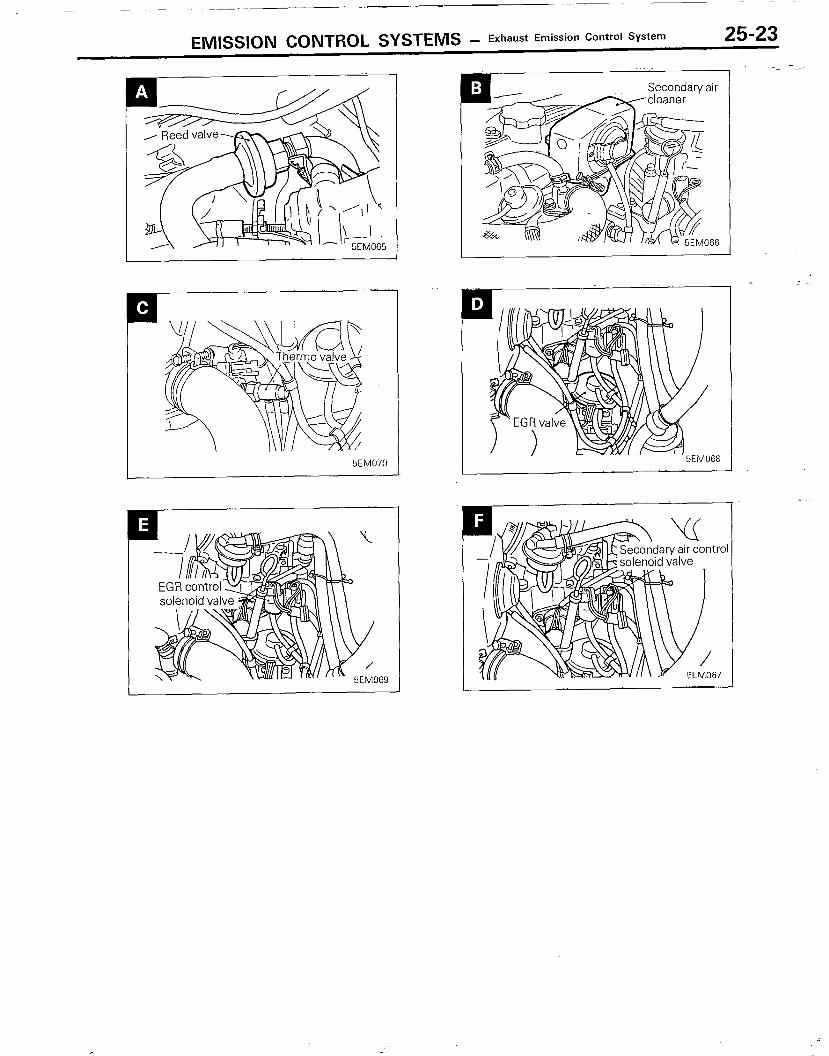
EMISSION CONTROL SYSTEMS - Exhaust Emission Control System 25-23
6EM070

25-24 EMISSION CONTROL SYSTEMS - Exhaust Emission Control System
AIR-FUEL RATIO CONTROL (ECl) SYSTEM N25lCAB.a
Heter to GROUP- 14 FUEL SYWEM - Service Adystment Procedures tor the InspectIon -ot the air-fuel ratlo control (EC11 ~:~‘jsTem.
THREE-WAY CATALYTIC CONVERTER N25lCBAa
REMOVAL AND INSTALLATION
For removal and rnstallatlon procedures, reter-to GROUP 11 INTAKE AND EXHAUST SYSTEM - Exhaust Pipes and Muf- tiers.
INSPECTION
cI:heck tor damage, cracks or tusron and replace iI taulty.
Caution 1. Operation of any type, including idling, should be
avoided if engine misfiring occurs. Under this condition the exhaust system will operate at abnormally high temperature;which may cause damage to the catalyst or under-body parts of the vehicle.
2. Alteration or deterioration of ignition or fuel system, or any type of operating condition which results in engine misfiring must be corrected to avoid overheating the catalytic converters.
3. Proper maintenance and tuneup according to manufac- turer’s specifications should be made to correct the conditions as soon as possible.
iocker cover Secondary air InjectIon 1 cleaner ! mixer i
Intake manifold
air Inlet 5EM075
SECONDARY AIR SUPPLY SYSTEM INSPECTION
N25lCCCa
Put a finger at the end of the extension hose to check air suction.
Caution When a suction is felt by this inspection procedure, use care not to be sealded by exhaust gas flowing backward due to breakage of reed valve.
EMISSION CONTROL SYSTEMS - Exhaust Emission Control System 25b25
5EM076
Exhaust
side & manifold Air cleaner
3EM17(
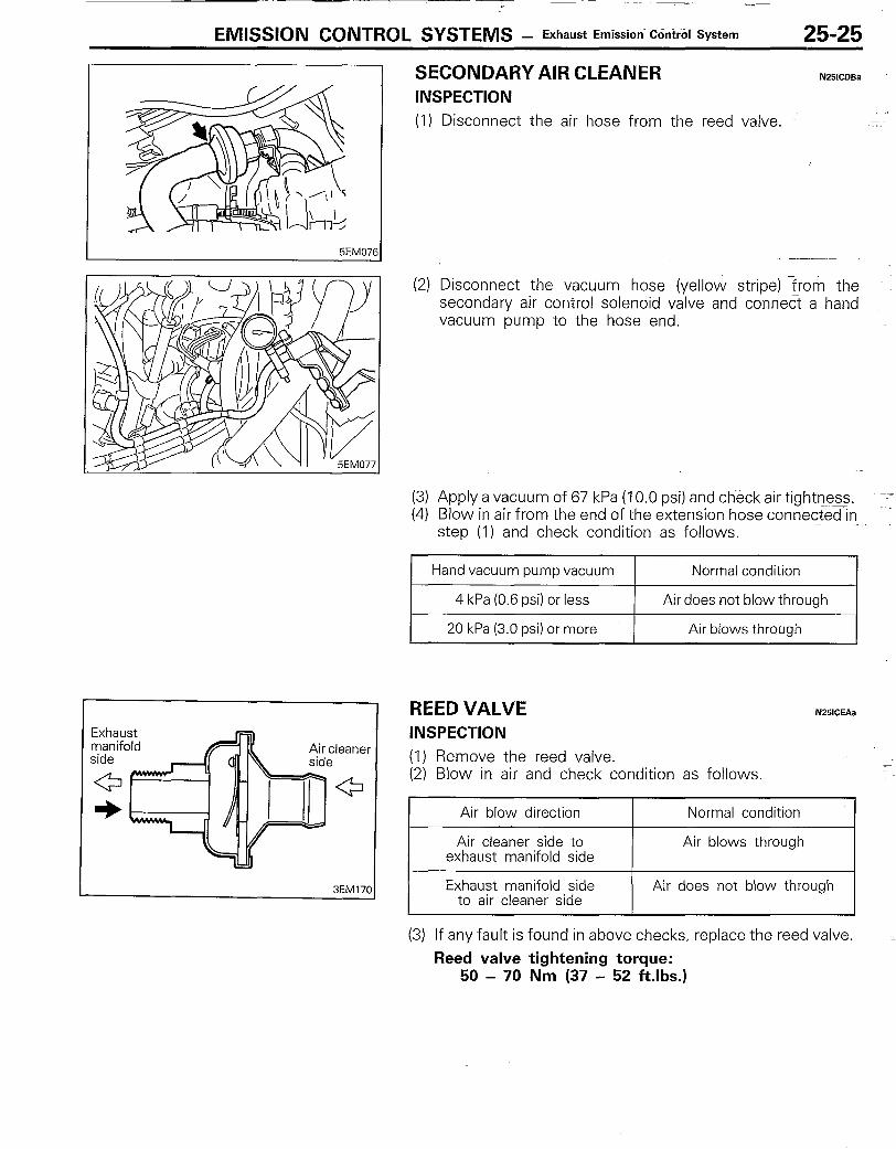
SECONDARY AIR CLEANER INSPECTION
N251CDBa
(1) Disconnect the air hose from the reed valve. ‘- =-~=
.-
(2) Disconnect the vacuum h&e (yellow stripe) rrom the secondary air control solenoid valve and connect a hand vacuum pump to the hose end.
(3) Apply a vacuum of 67 kPa (10.0 psi) and check air tightness. --; (4) Blow in air from the end of the extension hose connected-in
step (1) and check condition as follows.
REED VALVE INSPECTION
N25lCEAa
(1) Remove the reed valve. (2) Blow in air and check condition as follows.
Air blow direction Normal condition
Air cleaner side to Air blows through exhaust manifold side
Exhaust manifold side to air cleaner side
Air does not blow through
(3) If any fault is found in above checks, replace the reed valve. Reed valve tightening torque:
50 - 70 Nm (37 - 52 ftlbs.)
EMISSION CONTROL SYSTEMS - Exhaust Emission Control System
,
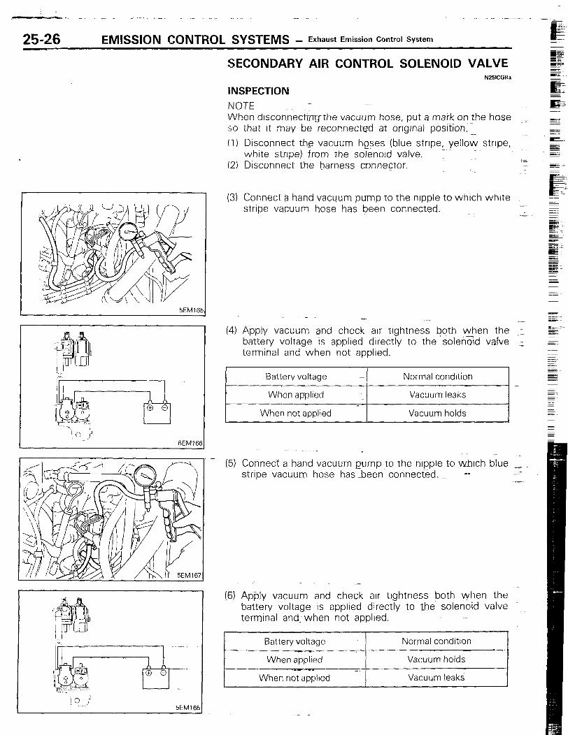
SECONDARY AIR CONTROL SOLENOID VALVE N25lCFBa
lNSPECTlON NOTE When drsconnecbthe vacuum hose, put a mark on the hose __ so that It may be reconnected at orrgrnal position, .._ (I) Disconne.ct the vacuum hqses (blue strrpe, yellow stripe, ~~
whrte stripe) from the solenord valve. ~~ (2) Disconnect the harness connector. -
I 5EM1651
(3) Connect a hand vacuum pump to the nrpple to whrch white _~ stripe vacuum hose has been connected.
_~- -”
(4) Apply vacuum and check arr tightness both when the 1 battery voltage is applied directly to the ‘solen-d;ld valve 1, terminal and when not applied.
Battery voltage
When applied
When not applied
Normal condition
Vacuum leaks
Vacuum holds
(51 Connect a hand vacuum pump to the nrpple to whrch blue _ stripe vacuum hose hasbeen connected, =I
-
(6) Apply vacuum and check air trghtness both ~when the battery volta-ge is applied directly to the solenoid valve - terminal Andy when not applied.
Battery voltage
5EM16C
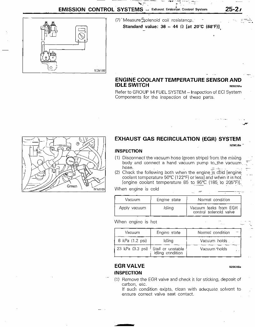
(fS--Measuresolenoid coil resistance. - Standard value: 36 - 44 CR [at 20°C (68”F)];
-~ a
ENGINE COOLANT TEMPERATURE SENSOR AND IDLE SWITCH N251CHAa
Refer to GROUP 14 FUEL SYSTEM - Inspection of ECI System Components for the inspection of these parts.
EXHAUST GAS RECIRCULATION (EGR) SYSTEM .~ N25iCJBa--~
INSPECTION (1) Disconnect the vacuum hose (green stripe) from the mixing
~_~~ ~~_
body and connect a hand vacuum pump to--the vacuum-, F hose.
(2) Check the following both when the engineJszcbld [engine : _ coolant temperature 50°C (122°F) or less] and when it is hot Iengine coolant temperature 85 to SSQ185. to 2Q5”F)I.
When engine is cold
Vacuum Engine state
Apply vacuum Idling
Normal condition
Vacuum- leaks from EGR control solenoid. valve
When engine is hot
EGR VALVE N25lCKBa
INSPECTION (1) Remove the EGR valve and check jt for sticking, deposit of
carbon, etc. If such condition exists, clean with adequate. solvent to _p ensure correct valve seat contact.
EMISSION CONTROL SYSTEMS - Exhaust Emission Control System
lEM15f
I 0 i 5EM17;
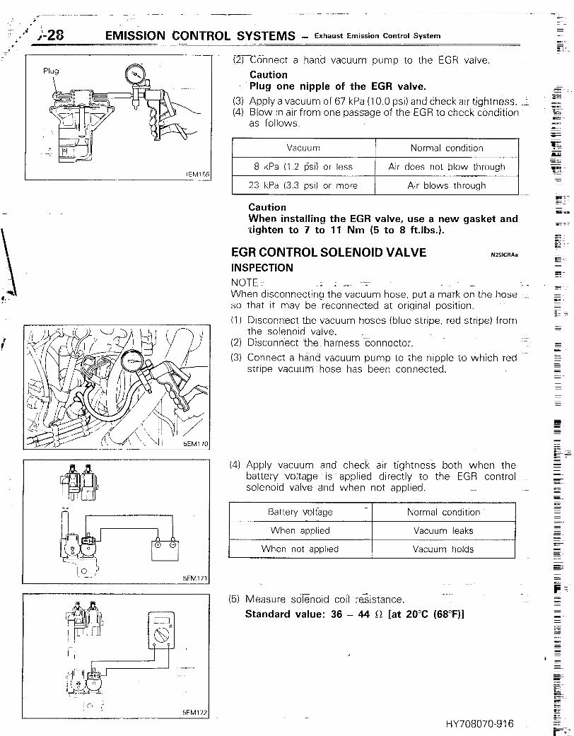
(2) Connect a hand vacuum pump to the EGR valve. Caution Plug one nipple of the EGR valve.
(3) Apply a vacuum of 67 kPa (10.0 psi) and check air tightness. -I (4) Blow in air from one pasage of the EGR to check condition
as follows.
Vacuum Normal condition I
I 8 kPa (1.2 psi) or less ( Air does not blow through 1
23 kPa (3.3 psi) or more I Air blows through
Caution When installing the EGR valve, use a new gasket and tighten to 7 to 11 Nm (5 to 8 ftlbs.).
EGR CONTROL SOLENOID VALVE INSPECTION
NOTE
N251CRAa
When disconnecting the vacuum hose, put a mark on the hose _ so that it may beg reconnected at original position.
(I 1 Disconnect the-vacuum hoses (blue stripe, red stripe) from the solenoid--valve.
(2) Disconnect the harness connector. (3) Connect a hand vacuum pump to the nipple to which red .-
stripe vacuum whose has been connected.
(4) Apply vacuum and check air tightness both when the battery~ voltage is applied directly to the EGR control solenoid valve and when not applied.
Battery voltage Normal condition
When applied
When not applied
Vacuum leaks
Vacuum holds
(5) Measure solenoid coil resistance.
Standard value: 36 - 44 il [at 20°C (68”F)I
HY70BO70-916