EMISSION CONTROL SYSTEMS - Welcome to the Supra Club of New Zealand
22
EMISSION CONTROL SYSTEMS Page ............................................. SYSTEM PURPOSE EC-2 COMPONENT LAYOUT AND SCHEMATIC DRAWING (7M-GE) ......................................... EC-3 COMPONENT LAYOUT AND SCHEMATIC DRAWING (7M-GTE) ...................................... EC-4 POSITIVE CRANKCASE VENTILATION (PCV) SYSTEM ........................................................ EC-5 FUEL EVAPORATIVE EMISSION CONTROL (EVAP) SYSTEM ........................................ EC-6 .................................... DASH POT (DP) SYSTEM EC-8 EXHAUST GAS RECIRCULATION (EGR) ............................................ SYSTEM (7M-GE) EC-12 EXHAUST GAS RECIRCULATION (EGR) .......................................... SYSTEM (7M-GTE) EC-16 .............. THREE-WAY CATALYST (TWC) SYSTEM EC-20 NOTE: TROUBLESHOOTING (See pages EM-4 to 6)
Transcript of EMISSION CONTROL SYSTEMS - Welcome to the Supra Club of New Zealand

EMISSION CONTROL SYSTEMS
Page
............................................. SYSTEM PURPOSE EC-2
COMPONENT LAYOUT AND SCHEMATIC DRAWING (7M-GE) ......................................... EC-3
COMPONENT LAYOUT AND SCHEMATIC DRAWING (7M-GTE) ...................................... EC-4
POSITIVE CRANKCASE VENTILATION (PCV) SYSTEM ........................................................ EC-5
FUEL EVAPORATIVE EMISSION CONTROL (EVAP) SYSTEM ........................................ EC-6
.................................... DASH POT (DP) SYSTEM EC-8
EXHAUST GAS RECIRCULATION (EGR) ............................................ SYSTEM (7M-GE) EC-12
EXHAUST GAS RECIRCULATION (EGR) .......................................... SYSTEM (7M-GTE) EC-16
.............. THREE-WAY CATALYST (TWC) SYSTEM EC-20
NOTE: TROUBLESHOOTING (See pages EM-4 to 6)

EC-2 EMISSION CONTROL SYSTEMS - Svstem P u r ~ o s e
System -. -- - - - --
Positive crankcase ventilation
Fuel evaporative emission control
Dash pot
Exhaust gas recirculation
Three-way catalyst
Electronic fuel injection *
SYSTEM PURPOSE
Abbreviation 1 Purpose
PCV
EVAP
D P
EG R
TWC
EFI
-- - -- .-
Reduces blow-by gas (HC)
Reduces evaporative HC
Reduces HC and CO
Reduces NOx
Reduces HC, CO and NOx
Regulates all engine conditions for reduction of exhaust emissions.
* For inspection and repair o f the EFI system, refer t o EFI Section.

EMISSION CONTROL SYSTEMS - Component Layout and Schematic Drawing (7M-GE) EC-3
COMPONENT LAYOUT AND SCHEMATIC DRAWING (7M-GE)
TWC I
Sub-oxygen Sensor (Calif. only)
EGR Cooler
EC3341

EC-4 EMISSION CONTROL SYSTEMS - Component Layout and Schematic Drawing (7M-GTE)
COMPONENT LAYOUT AND SCHEMATIC DRAWING (7M-GTE)
I il vsv
EGR Vacuum
EGR Cooler

EMISSION CONTROL SYSTEMS - Positive Crankcase Ventilation (PCV) System EC-5
POSITIVE CRANKCASE VENTILATION (PCV) SYSTEM
Air Cleaner
Blow-By Gas-
Fresh Air - - - -
7M-GTE Air Cleaner
PCV
Hose
Hose
To reduce HC emlsslons, crankcase blow-by gas (HC) i s routed to the intake manifold for combustion In the cylinders.
Orifice
Air
\ '\
INSPECTION OF PCV HOSE AND CONNECTIONS
1. VISUALLY INSPECT HOSE AND CONNECTIONS
Check for cracks, leaks or damage.
2. CLEAN ORIFICE(S)
Clean off any gum deposits in the orifice(s1 w i th solvent and b low out w i th compressed air.
EC-6 EMISSION CONTROL SYSTEMS - Fuel Evaporative Emission Control (EVAP) System
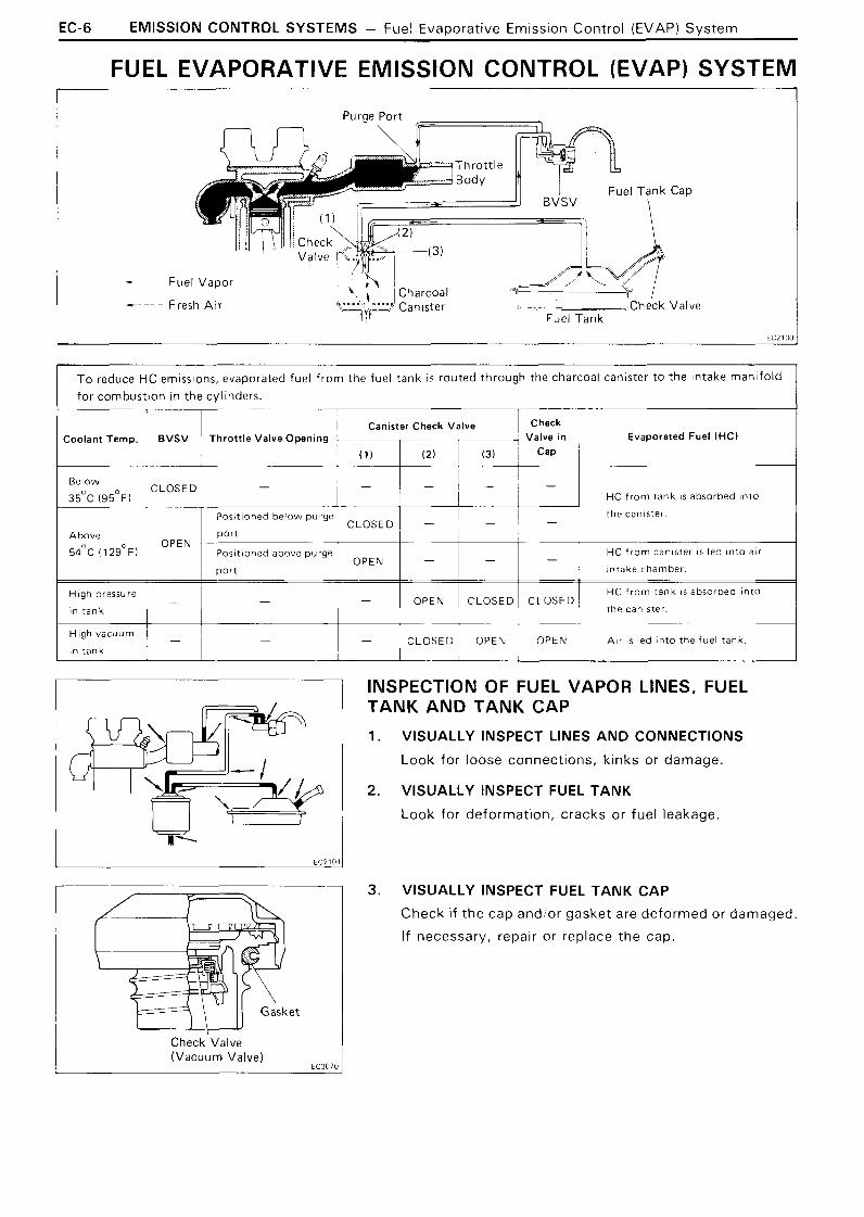
FUEL EVAPORATIVE EMISSION CONTROL (EVAP) SYSTEM
- Fuel Vapor
--- Fresh Air
-- - - --
To reduce HC emlsslons, evaporated fuel from the fuel tank IS routed through the charcoal canlster to the Intake man~fold for combustion In the cylinders
Coolant Temp.
Below
3 5 ' ~ ( 9 5 ' ~ )
Above
5 4 ' ~ ( 1 2 9 ' ~ )
H ~ g h pressure
In tank
High vacuum
in tank
T 1 ~ a n s t e r check valve 1 Check ~ BVSV Throttle Va lve Open~ng ; , Valve ~n Evaporated Fuel (HCI I I (1) (21
- I I HC from tank IS absorbed lnto
1 HC from tank I S absorbed lnto
the canlster 1 1 1 I
OPEN
- I - 1 - CLOSED OPEN OPEN ,411 I S led ~ n t o the fuel tank
Positoned below purge
INSPECTION OF FUEL VAPOR LINES, FUEL TANK A N D T A N K C A P
1. VISUALLY INSPECT LINES AND CONNECTIONS
Look for loose connections, kinks or damage.
CLOSED port
Pos~t~oned above purge
2. VISUALLY INSPECT FUEL TANK
Look for deformation, cracks or fuel leakage
I
I 1 - - -
- port
3. VISUALLY INSPECT FUEL TANK CAP
Check if the cap andlor gasket are deformed or damaged.
If necessary, repair or replace the cap.
OPEN
check'valve (Vacuum Valve)
EC3070
- - I HC from canlster I S led Into alr
~ntake chamber

EMISSION CONTROL SYSTEMS - Fuel Eva~ora t i ve Emission Control (EVAP) Svstem EC-7
Tank P i ~ e
Purge Pipe I I
Below
Closed
- Cool Water
Above 54'~ ( 1 2 9 " ~ )
INSPECTION OF CHARCOAL CANISTER
1. REMOVE CHARCOAL CANISTER
2. VISUALLY INSPECT CHARCOAL CANISTER CASE
Look for cracks or damage.
3 . CHECK FOR CLOGGED FILTER AND STUCK CHECK VALVE
(a) Using low pressure compressed air, blow into the tank pipe and check that air f lows wi thout resistance f rom the other pipes.
(b) Blow into the purge pipe and check that air does not f low f rom the other pipes.
If a problem is found, replace the charcoal canister.
4. CLEAN FILTER IN CANISTER
Clean the filter by blowing 3 kg icm2(43 psi, 2 9 4 kPa)of compressed air into the tank pipe while holding the other upper canister pipe closed.
HINT: D o not attempt t o wash the canister.
No activated carbon should come out.
5. INSTALL CHARCOAL CANISTER
INSPECTION OF BVSV
CHECK BVSV BY BLOWING AIR INTO PIPE
(a) Drain the coolant from the radiator into a suitable con- tainer.
(b) Remove the BVSV.
(c ) Cool the BVSV to below 35OC (95OF) wi th cool water.
(d) Blow air into a pipe and check that the BVSV is closed.
(e) Heat the BVSV to above 54OC (12g°F) w i th hot water.
( f ) Blow air into a pipe and check that the BVSV is open.
If a problem is found, replace the BVSV.
(g) Apply sealant t o the threads of the BVSV and reinstall.
Sealant: Part No.08833-00070, THREE BOND 1324 or equivalent
(h) Fill the radiator w i th coolant.

EC-8 EMISSION CONTROL SYSTEMS - Dash Pot (DP) System
DASH POT (DP) SYSTEM
Normal Driving
I DP Diaphragm
Deceleration
I DP Diaphragm
To reduce HC and Co emissions, when decelerating the dash pot opens the throttle valve slightly more than at idle. This causes the air-fuel mixtu re to burn completely.
Idling
Condition
Pushed in by return force of throttle valve
1 CLOSED 1 Idle speed position
I
Diaphragm
I I
VTV
Normal driving
Deceleration
Throttle Valve
1 Pushed out by diaphragm spring
Pushed in by return force of throttle valve / Slightly opens and then slowly closes
to idle position
OPEN High speed position
EMISSION CONTROL SYSTEMS - Dash Pot (DP) Svs tem EC-9
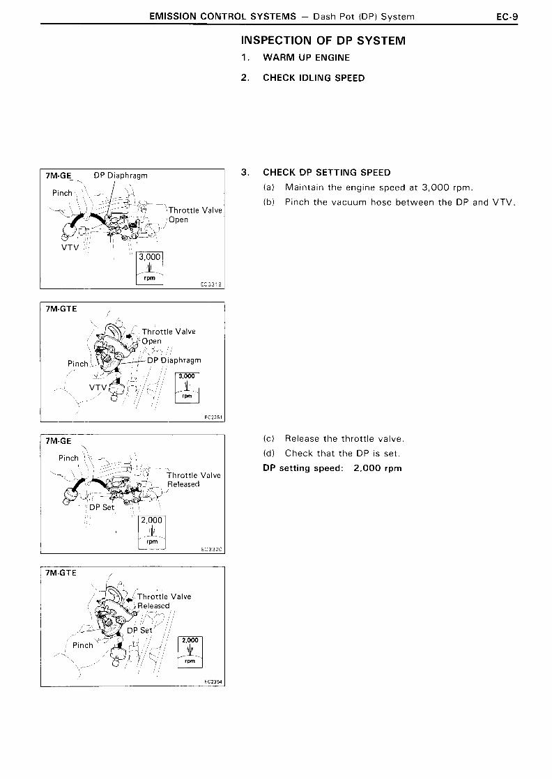
7M-GE DP Diaphragm I
Throttle Valve !open
VTV I I 13,0001
Throttle Valve
Valve
INSPECTION OF DP SYSTEM 1. WARM UP ENGINE
2. CHECK IDLING SPEED
3. CHECK DP SETTING SPEED
(a) Mainta in the engine speed a t 3,000 rpm.
( b l Pinch the vacuum hose be tween t he DP and VTV.
( c ) Release the throt t le valve.
( d ) Check tha t the DP is set.
DP setting speed: 2,000 rprn

EC-10 EMISSION CONTROL SYSTEMS - Dash Pot (DP) Svstem
7M-GE Release '
Approx. 1 Second
If not at the specified speed, adjust w i th the DP adjusting screw.
4. CHECK OPERATION OF VTV
(a) Set the DP speed in the same procedure as above; (a) t o (c) .
(b) Release the pinched hose and check that the engine returns t o idle speed in approx. 1 second.
IF NO PROBLEM IS FOUND WITH THIS INSPECTION, THE SYSTEM IS OKAY; OTHERWISE INSPECT EACH PART

EMISSION CONTROL SYSTEMS - Dash Pot (DP) Svstem EC-11
(Black) - Air
E C O l O
INSPECTION OF VTV
CHECK AND CLEAN FILTER ON VTV
(a) Check the filter for contamination or damage
(b) Using compressed air, clean the fi lter.
CHECK VTV BY BLOWING AIR INTO EACH SIDE
(a ) Check that air f lows wi thout resistance f rom B t o A.
(b ) Check that air f lows w i th dif f iculty f rom A t o 6.

EC-12 EMISSION CONTROL SYSTEMS - Exhaust Gas Recirculation (EGR) Sys tem (7M-GE)
EXHAUST GAS RECIRCULATION (EGR) SYSTEM (7M-GE)
EG R Vacuum
EGR Port R Port Modulator GR alve
EGR Port
/ R Port
EGR Port
/ R, Port
(3)
EGR Port
To reduce NOx emissions, part of the exhaust gases are recirculated through the EGR valve to the intake manifold to lower combustion temperature.
Coolant
Above 6 3 ' ~ ( 1 4 5 ' ~ )
*Engine Throt t le Valve Pressure i n the EGR EGR vacuum 1 EGR RPM
VSv Opening Angle 1 Valve Pressure Chamber Modulator Valve
Below Positioned be- * * ~ r e s e con- 1 oPENs Passage CLOSED
stantly alter- atmosphere recirculated CLOSED tween EGR por t and R por t nating between CLOSES passage OPEN
HIGH low and high t o a tmos~here Reclrculated
Exhaust Gas
I I
%>cuated
I reclrculated
Z L l a t e d
- OPEN - - - '
* * Pressure increase-Modulator closes --EGR valve opens---Pressure drops :EGR valve close- Modulator opens-
Positioned above
* * * When the throttle valve i s positioned above the R port, the EGR vacuum modulator will close the atmosphere passage and open the EGR valve to increase the EGR gas, even if the exhaust pressure is insufficiently low.
CLOSED Above OPEN - - - 5,200 rpm
Pos~tioned below EGR por t
(3 ) !,,, 1 Recirculated CLOSES passage 1 OPEN
-
R port
-
Engine RPM control is for Calif. only.
H IGH t o atmosphere (increase)

EMISSION CONTROL SYSTEMS - Exhaust Gas Recirculation (EGR) System (7M-GE) EC-13
Filter
- Vacuum Gauge I
I 2,500 rpm No Vacuum
Tachometer Vacuum Gauge
HOT 2,500 rpm Low Vacuum
INSPECTION OF EGR SYSTEM
CHECK AND CLEAN FILTER IN EGR V A C U U M MODULATOR
(a) Check the filter for contamination or damage.
(b) Using compressed air, clean the fi lter.
PREPARATION
Using a 3-way connector, connect a vacuum gauge t o the hose between the EGR valve and EGR vacuum modulator.
CHECK SEATING OF EGR VALVE
Start the engine and check that the engine starts and runs a t idle.
CHECK VSV WlTH COLD ENGINE
(a) The coolant temperature should be below 57OC ( 1 35OF).
(b) Check that the vacuum gauge indicates is zero at 2 ,500 rpm.
CHECK VSV AND EGR VACUUM MODULATOR WlTH WARM ENGINE
(a) Warm up the engine.
(b ) Check that the vacuum gauge indication is approx. 7 0 mmHg (2 .76 in.Hg, 9.3 kPa) at 2 ,500 rpm.
(c ) Check that the vacuum gauge indication is zero at idle.
Tachometer Vacuum Gauge EC0137 EC0129
(d) Disconnect the vacuum hose f rom R port of the EGR vacuum modulator and connect R port directly t o the intake manifold w i th another hose.
(e l Check that the vacuum gauge indicates high vacuum at 2,500 rpm.
HINT: As a large amount of EGR gas enters, the engine wi l l misfire slightly.
( f ) Disconnect the vacuum gauge and reconnect the vacuum hoses t o the proper locations.
EC-14 EMISSION CONTROL SYSTEMS - Exhaust Gas Recirculation (EGR) System (7M-GE)
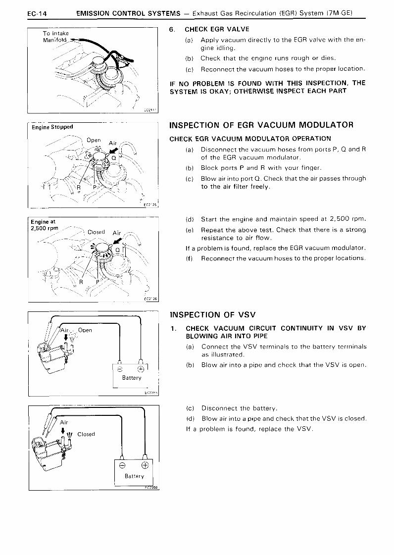
Engine Stopped
EC212'
Engine at
Battery
6. CHECK EGR VALVE
(a) Apply vacuum directly t o the EGR valve w i th the en- gine idling.
(b) Check that the engine runs rough or dies.
(c) Reconnect the vacuum hoses t o the proper location.
IF NO PROBLEM IS FOUND WITH THIS INSPECTION, THE SYSTEM IS OKAY; OTHERWISE INSPECT EACH PART
INSPECTION OF EGR VACUUM MODULATOR
CHECK EGR VACUUM MODULATOR OPERATION
(a) Disconnect the vacuum hoses from ports P, Q and R of the EGR vacuum modulator.
(b) Block ports P and R w i th your finger.
( c ) Blow air into port Q. Check that the air passes through t o the air filter freely.
(d) Start the engine and maintain speed at 2,500 rpm.
(el Repeat the above test. Check that there is a strong resistance t o air f low.
If a problem is found, replace the EGR vacuum modulator.
( f ) Reconnect the vacuum hoses to the proper locations.
INSPECTION OF VSV
1. CHECK VACUUM CIRCUIT CONTINUITY IN VSV BY BLOWING AIR INTO PIPE
(a) Connect the VSV terminals t o the battery terminals as illustrated.
(b) Blow air into a pipe and check that the VSV is open.
(c ) Disconnect the battery.
(d l Blow air into a pipe and check that the VSV is closed.
If a problem is found, replace the VSV.
EMISSION CONTROL SYSTEMS - Exhaust Gas Recirculation (EGR) System (7M-GE) EC-15
No continuity I
Ohmmeter
R
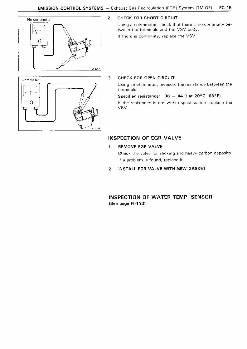
2. CHECK FOR SHORT CIRCUIT
Using an ohmmeter, check that there is no continuity be- tween the terminals and the VSV body.
If there is continuity, replace the VSV.
3. CHECK FOR OPEN CIRCUIT
Using an ohmmeter, measure the resistance between the terminals.
Specified resistance: 3 8 - 44 R at 20°C (68OF)
If the resistance is not wi th in specification, replace the VSV.
INSPECTION OF EGR VALVE
1. REMOVE EGR VALVE
Check the valve for sticking and heavy carbon deposits.
If a problem is found, replace it.
2 . INSTALL EGR VALVE WITH NEW GASKET
INSPECTION OF WATER TEMP. SENSOR (See page FI-113)

EC-16 - EMISSION CONTROL SYSTEMS - Exhaust Gas Recirculation (EGR) System (7M-GTE)
EXHAUST GAS RECIRCULATION (EGR) SYSTEM (7M-GTE)
EGR Vacuum Modulator
(2)
EGR Port
EGR Port
To reduce NOx emissions, part of the exhaust gases are recirculated through the EGR valve to the intake manifold to lower
N o t 1 recirculated
the maximum combustion temperature.
Coolant Temp.
passage and open the EGR valve to increase the EGR gas, even i f the exhaust pressure is insufficiently low. I
~ b o v e 6 3 ' ~ ( 1 4 5 ' ~ )
V S V Throttle Valve Opening Angle
* When the throttle valve is positioned above the EGR port, the EGR vacuum modulator will close the atmosphere
OPEN
(E-G)
Pressure in the EGR Valve Pressure Chamber
Positioned below . EGR por t
Positioned above EGR por t
EGR Vacuum Modulator
( 1 )
(2)
EG R Valve
Exhaust Gas
-
i
-
CLOSES passage to atmosphere
OPEN
N o t recirculated
Recircu lated (increase)
EMISSION CONTROL SYSTEMS - Exhaust Gas Recirculation (EGR) System (7M-GTE) EC-17
Vacuum Gauge
COLD 2.500 r ~ m No Vacuum
Tachometer Vacuum Gauge
HOT 2,500 rpm Low Vacuum
Tachometer Vacuum Gauge E C O l 3 7 E C 0 1 2 '
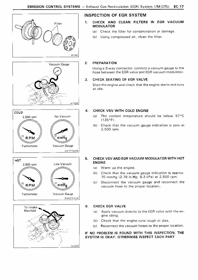
INSPECTION OF EGR SYSTEM
CHECK AND CLEAN FILTERS IN EGR VACUUM MODULATOR
(a) Check the filter for contamination or damage.
(b ) Using compressed air, clean the filter.
PREPARATION
Using a 3-way connector, connect a vacuum gauge t o the hose between the EGR valve and EGR vacuum modulator.
CHECK SEATING OF EGR VALVE
Start the engine and check that the engine starts and runs at idle.
CHECK VSV WlTH COLD ENGINE
(a) The coolant temperature should be below 57OC ( 1 35OF).
(b ) Check that the vacuum gauge indication is zero at 2 ,500 rpm.
CHECK VSV AND EGR VACUUM MODULATOR WlTH HOT ENGINE
(a) Warm up the engine.
(b ) Check that the vacuum gauge indication is approx. 7 0 mmHg (2 .76 in.Hg, 9 . 3 kPa) at 2 ,500 rpm.
(c) Disconnect the vacuum gauge and reconnect the vacuum hose t o the proper location.
CHECK EGR VALVE
(a) Apply vacuum directly t o the EGR valve w i th the en- gine idling.
(b) Check that the engine runs rough or dies.
(c) Reconnect the vacuum hoses t o the proper location.
IF NO PROBLEM IS FOUND WlTH THIS INSPECTION, THE SYSTEM IS OKAY; OTHERWISE INSPECT EACH PART
EC-18 EMISSION CONTROL SYSTEMS - Exhaust Gas Recirculation (EGR) Svstem (7M-GTE)
I Engine 1
No continuity
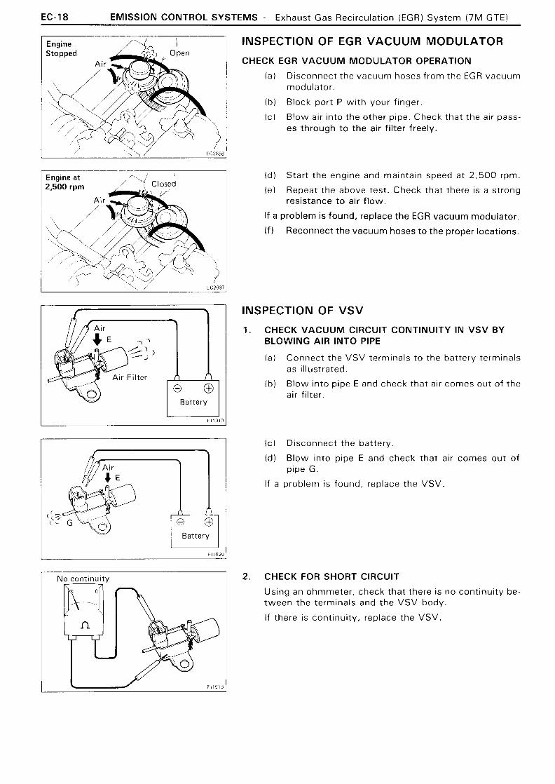
INSPECTION OF EGR VACUUM MODULATOR
CHECK EGR VACUUM MODULATOR OPERATION
(a) Disconnect the vacuum hoses f rom the EGR vacuum modulator.
(b) Block port P w i th your finger.
( c ) Blow air into the other pipe. Check that the air pass- es through t o the air filter freely.
(d l Start the engine and maintain speed at 2,500 rpm.
(e) Repeat the above test. Check that there is a strong resistance t o air f low.
If a problem is found, replace the EGR vacuum modulator.
( f ) Reconnect the vacuum hoses t o the proper locations.
INSPECTION OF VSV
1. CHECK VACUUM CIRCUIT CONTINUITY IN VSV BY BLOWING AIR INTO PIPE
(a) Connect the VSV terminals t o the battery terminals as illustrated.
(b) Blow into pipe E and check that air comes out of the air f i l ter.
(c ) Disconnect the battery.
(d) Blow into pipe E and check that air comes out of pipe G.
If a problem is found, replace the VSV.
2. CHECK FOR SHORT CIRCUIT
Using an ohmmeter, check that there is no continuity be- tween the terminals and the VSV body.
If there is continuity, replace the VSV.

EMISSION CONTROL SYSTEMS - Exhaust Gas Recirculation (EGR) Svstem (7M-GTE) EC-19
3. CHECK FOR OPEN CIRCUIT
Using an ohmmeter, measure the resistance between the terminals.
Specified resistance: 38 - 44 fl at 20°C (68OF)
If the resistance is not wi th in specification, replace the VSV.
INSPECTION OF EGR VALVE
1. REMOVE EGR VALVE
Check the valve for sticking and heavy carbon deposits. if a problem is found, replace i t .
2. INSTALL EGR VALVE WITH NEW GASKET
INSPECTION OF WATER TEMP. SENSOR (See page FI-113)

EC-20 EMISSION CONTROL SYSTEMS - T h r e e - W a v Ca ta l vs t ( T W C ) Svs te rn
THREE-WAY CATALYST (TWC) SYSTEM 7M-GE (Federal and Canada)
7M-GE (California) Three-Way Catalyst (Monolithic)
NOx, CO, HC l - 7
COZ. N2. Hz0 -1 Three-Wav Catalvst
( ~ o n o l i t h i c ) Three-Way Catalyst EC3427
(Monolithic) EC3340 EC2907
( ~ o n o l i t h i c ) ' Three-Way Catalyst Iblnnnlithir)
7M-GTE n
E
To reduce HC, CO and NOx emissions, they are oxidized, reduced and converted to nitrogen (N2 ), carbon dioxide (C02 ) and water ( H 2 0 ) by the catalyst.
-
Exhaust Port - 1 Exhaust Gas I
Three-Wav Catalvst
COz,Nz.HzO l ,
HC, CO, AND NOx , OXIDATION AND co2 REDUCTION H2 0
N 2

EMISSION CONTROL SYSTEMS - Three-Wav Catalvst (TWC) System EC-2 1
INSPECTION OF EXHAUST PIPE ASSEMBLY
1. CHECK CONNECTIONS FOR LOOSENESS OR DAMAGE
2. CHECK CLAMPS FOR WEAKNESS, CRACKS OR DAMAGE
INSPECTION OF CATALYTIC CONVERTER
CHECK FOR DENTS OR DAMAGE
If any part of the protector is damaged or dented t o the extent that i t touches the catalyst, repair or replace it.
2. CHECK FOR ADEQUATE CLEARANCE BETWEEN CATA- LYTIC CONVERTER AND HEAT INSULATOR
H e a t l nsu lator
REPLACEMENT OF CATALYTIC CONVERTER
1. REMOVE CONVERTER
(a) Jack up the vehicle.
(b) Check that the converter is cool.
(c ) Remove the bolts at the front and rear of the con- verter.
(d) Remove the converter and gaskets.
INSPECTION OF HEAT INSULATOR
1. CHECK HEAT INSULATOR FOR DAMAGE
2. INSTALL CONVERTER
(a) Place new gaskets on the converter front and rear pipes, and connect the converter t o the exhaust pipes.
(b) Tighten the bolts.
Torque: Catalyst-Exhaust pipe
440 kg-cm ( 3 2 ft-lb, 4 3 N - m )

- MEMO -