E.G.S. PILLAY ENGINEERING COLLEGE...
37
E.G.S. PILLAY ENGINEERING COLLEGE (Autonomous) Approved by AICTE, New Delhi | Affiliated to Anna University, Chennai Accredited by NAAC with “A‟ Grade | Accredited by NBA (CSE, EEE, MECH) NAGAPATTINAM – 611 002. DEPARTMENT OF MECHANICAL ENGINEERING M.E. - MANUFACTURING ENGINEERING FIRST SEMESTER 2017 - 2018 1704MF107 - INDUSTRIAL AUTOMATION AND MECHATRONICS LABORATORY LAB RECORD NAME : ---------------------------------- REG. NO. : ----------------------------------
Transcript of E.G.S. PILLAY ENGINEERING COLLEGE...
E.G.S. PILLAY ENGINEERING COLLEGE
(Autonomous)
Approved by AICTE, New Delhi | Affiliated to Anna University, Chennai
Accredited by NAAC with “A‟ Grade | Accredited by NBA (CSE, EEE, MECH)
NAGAPATTINAM – 611 002.
DEPARTMENT OF MECHANICAL ENGINEERING
M.E. - MANUFACTURING ENGINEERING
FIRST SEMESTER
2017 - 2018
1704MF107 - INDUSTRIAL AUTOMATION AND MECHATRONICS LABORATORY
LAB RECORD
NAME : ----------------------------------
REG. NO. : ----------------------------------
E.G.S. PILLAY ENGINEERING COLLEGE
(Autonomous)
Approved by AICTE, New Delhi | Affiliated to Anna University, Chennai
Accredited by NAAC with “A‟ Grade | Accredited by NBA (CSE, EEE, MECH)
NAGAPATTINAM – 611 002.
BONAFIDE CERTIFICATE
REGISTER NO.: -----------------------------
Certified to be the bonafide record of work done by-----------------------------------,
M.E. - Manufacturing Engineering / I Semester, during the year of 2017-2018.
Head of the Department Staff-in-charge
Submitted for practical examination held in ------------------ at E.G.S. Pillay Engineering
College, Nagapattinam – 611 002.
INTERNAL EXAMINER EXTERNAL EXAMINER
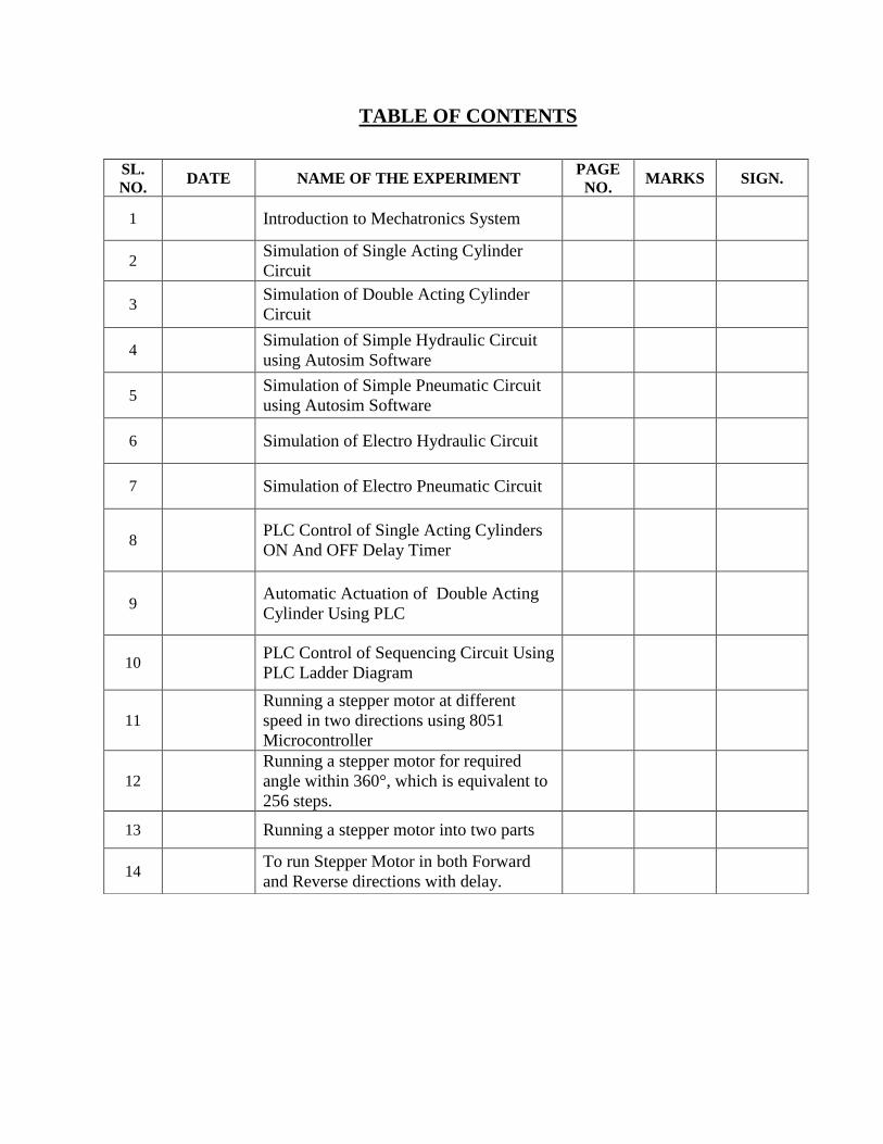
TABLE OF CONTENTS
SL.
NO. DATE NAME OF THE EXPERIMENT
PAGE
NO. MARKS SIGN.
1
Introduction to Mechatronics System
2 Simulation of Single Acting Cylinder
Circuit
3 Simulation of Double Acting Cylinder
Circuit
4 Simulation of Simple Hydraulic Circuit
using Autosim Software
5 Simulation of Simple Pneumatic Circuit
using Autosim Software
6
Simulation of Electro Hydraulic Circuit
7
Simulation of Electro Pneumatic Circuit
8
PLC Control of Single Acting Cylinders
ON And OFF Delay Timer
9
Automatic Actuation of Double Acting
Cylinder Using PLC
10
PLC Control of Sequencing Circuit Using
PLC Ladder Diagram
11
Running a stepper motor at different
speed in two directions using 8051
Microcontroller
12
Running a stepper motor for required
angle within 360°, which is equivalent to
256 steps.
13
Running a stepper motor into two parts
14 To run Stepper Motor in both Forward
and Reverse directions with delay.
EX.NO: 01 INTRODUCTION TO MECHATRONICS SYSTEM
DATE:
AIM:
To study about the important features, about Mechatronics system.
INTRODUCTION TO MECHATRONICS SYSTEM:
Mechatronics is one of the new and existing fields on the engineering landscape,
subsuming parts of traditional engineering fields and requiring a broader approach to the design
of system that we can formally call as Mechatronics system. Many industries improving their
works through automation which is based on the inter connection between the electronic control
systems and mechanical engineering. Such control systems generally use microprocessors as
controllers and have electrical sensors extracting information from mechanical inputs through
electrical actuators to mechanical systems.
This can be considered to be application of computer based digital control techniques
through electronic and electric interfaces to mechanical engineering problems. Successful design
of Mechatronics can lead to products that are extremely attractive to customer in quality cost-
effectiveness.
MECHATRONICS DEFINITION:
Mechatronics may be defined as a multi-disciplinary field of study that implies the
synergistic integration of electronic engineering, electric engineering, control engineering and
computer technology with mechanical engineering for the design, manufacture, analysis and
maintenance of a wide range of engineering products and processes.
“Mechatronics brings together areas of technology involving sensors and measurement systems,
drive and actuation systems, analysis of the behavior of systems microprocessor systems”.
The integration across the traditional boundaries of mechanical engineering, electrical
engineering, electronics and control engineering has to occur at the earliest stages of the design
process if cheaper, more reliable; more flexible systems are to be developed.
APPLICATIONS OF MECHATRONICS ENGINEERING:
Mechatronics engineering finds application in the following fields.
Electronic home appliances
Electronic entertainment products
Engine systems (cars)
Large scale application
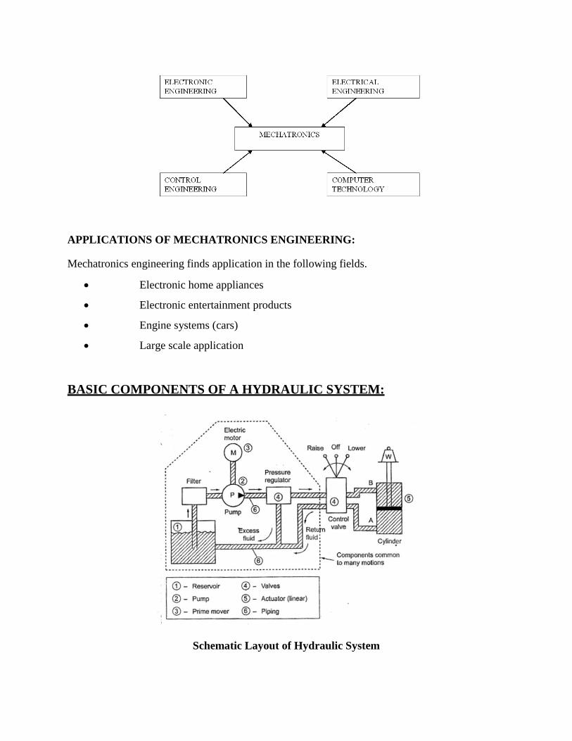
BASIC COMPONENTS OF A HYDRAULIC SYSTEM:
Schematic Layout of Hydraulic System
Reservoir (or air tank):
A reservoir is an oil supply tank. It is provided to hold the hydraulic liquid (usually oil).
Pump:
The pump is used to force the liquid into the system.
Prime mover:
A Prime mover, usually an electric motor, is used to drive the pump.
Valves:
Valves are refitted in the system to control liquid direction, pressure, and flow rate.
Actuator:
An actuator is provided to convert the liquid energy into mechanical force or torque to do useful
work. The actuator is the actual working element of the system. The actuators can be either
cylinders (to provide linear motion) or hydro motors (to provide rotary motion).
Fluid-transfer piping:
The hydraulic Piping is provided to carry the compressed liquid from one place to another.
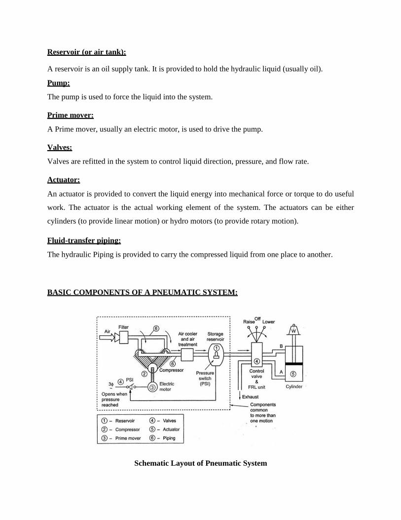
BASIC COMPONENTS OF A PNEUMATIC SYSTEM:
Schematic Layout of Pneumatic System
Reservoir (or air tank):
An air tank is provided to store the compressed air required for the operations.
Compressor:
The compressor is used to compress the atmospheric air so as to increase the pressure of the air.
Prime mover:
A Prime mover, usually an electric motor, is used to drive the compressor.
Valves:
Valves are refitted in the system to control air direction, pressure, and flow rate.
Actuator:
An actuator is provided to convert the air energy into mechanical force or torque to do useful
work.
Fluid-transfer piping:
Piping is provided to carry the compressed air from one place to another.
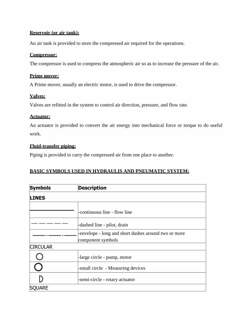
BASIC SYMBOLS USED IN HYDRAULIS AND PNEUMATIC SYSTEM:
Symbols Description
LINES
-continuous line - flow line
-dashed line - pilot, drain
-envelope - long and short dashes around two or more
component symbols
CIRCULAR
-large circle - pump, motor
-small circle - Measuring devices
-semi-circle - rotary actuator
SQUARE
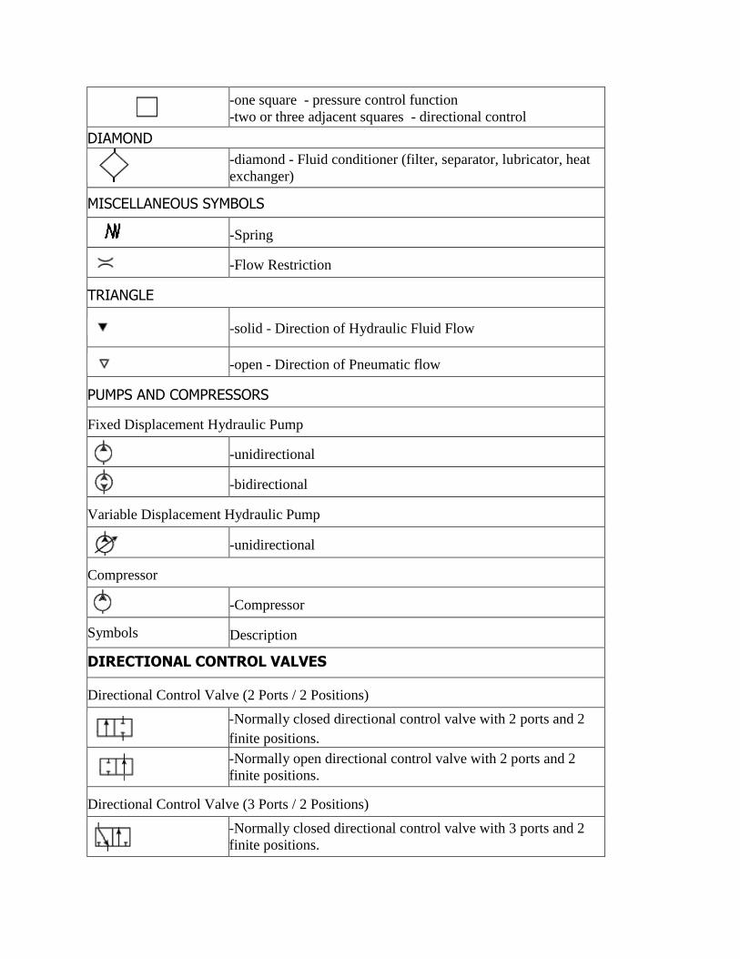
-one square - pressure control function
-two or three adjacent squares - directional control
DIAMOND
-diamond - Fluid conditioner (filter, separator, lubricator, heat
exchanger)
MISCELLANEOUS SYMBOLS
-Spring
-Flow Restriction
TRIANGLE
-solid - Direction of Hydraulic Fluid Flow
-open - Direction of Pneumatic flow
PUMPS AND COMPRESSORS
Fixed Displacement Hydraulic Pump
-unidirectional
-bidirectional
Variable Displacement Hydraulic Pump
-unidirectional
Compressor
-Compressor
Symbols Description
DIRECTIONAL CONTROL VALVES
Directional Control Valve (2 Ports / 2 Positions)
-Normally closed directional control valve with 2 ports and 2
finite positions.
-Normally open directional control valve with 2 ports and 2
finite positions.
Directional Control Valve (3 Ports / 2 Positions)
-Normally closed directional control valve with 3 ports and 2
finite positions.
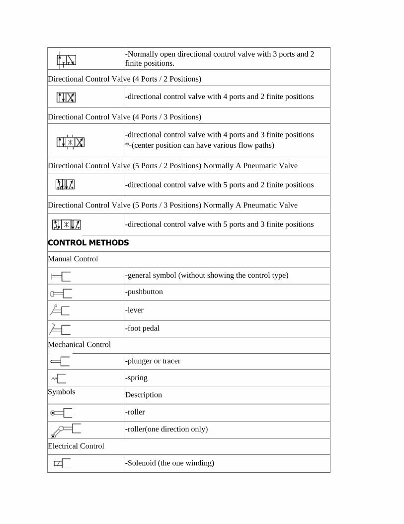
-Normally open directional control valve with 3 ports and 2
finite positions.
Directional Control Valve (4 Ports / 2 Positions)
-directional control valve with 4 ports and 2 finite positions
Directional Control Valve (4 Ports / 3 Positions)
-directional control valve with 4 ports and 3 finite positions
*-(center position can have various flow paths)
Directional Control Valve (5 Ports / 2 Positions) Normally A Pneumatic Valve
-directional control valve with 5 ports and 2 finite positions
Directional Control Valve (5 Ports / 3 Positions) Normally A Pneumatic Valve
-directional control valve with 5 ports and 3 finite positions
CONTROL METHODS
Manual Control
-general symbol (without showing the control type)
-pushbutton
-lever
-foot pedal
Mechanical Control
-plunger or tracer
-spring
Symbols Description
-roller
-roller(one direction only)
Electrical Control
-Solenoid (the one winding)
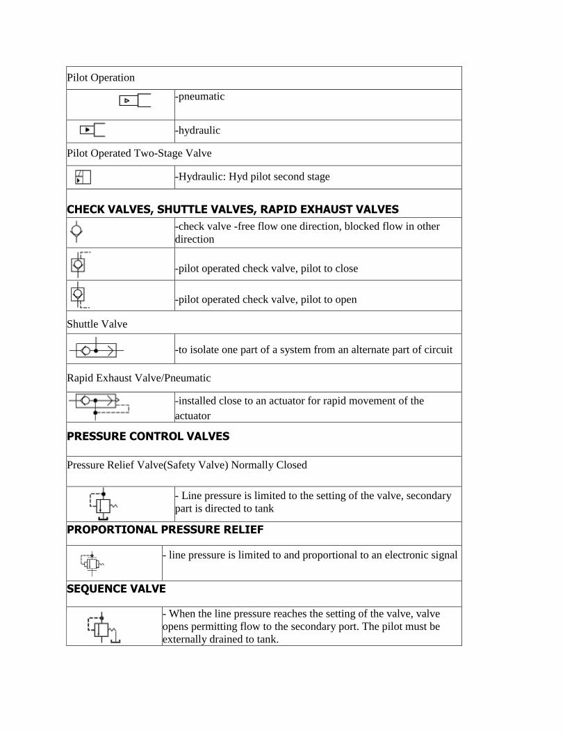
Pilot Operation
-pneumatic
-hydraulic
Pilot Operated Two-Stage Valve
-Hydraulic: Hyd pilot second stage
CHECK VALVES, SHUTTLE VALVES, RAPID EXHAUST VALVES
-check valve -free flow one direction, blocked flow in other
direction
-pilot operated check valve, pilot to close
-pilot operated check valve, pilot to open
Shuttle Valve
-to isolate one part of a system from an alternate part of circuit
Rapid Exhaust Valve/Pneumatic
-installed close to an actuator for rapid movement of the
actuator
PRESSURE CONTROL VALVES
Pressure Relief Valve(Safety Valve) Normally Closed
- Line pressure is limited to the setting of the valve, secondary
part is directed to tank
PROPORTIONAL PRESSURE RELIEF
- line pressure is limited to and proportional to an electronic signal
SEQUENCE VALVE
- When the line pressure reaches the setting of the valve, valve
opens permitting flow to the secondary port. The pilot must be
externally drained to tank.
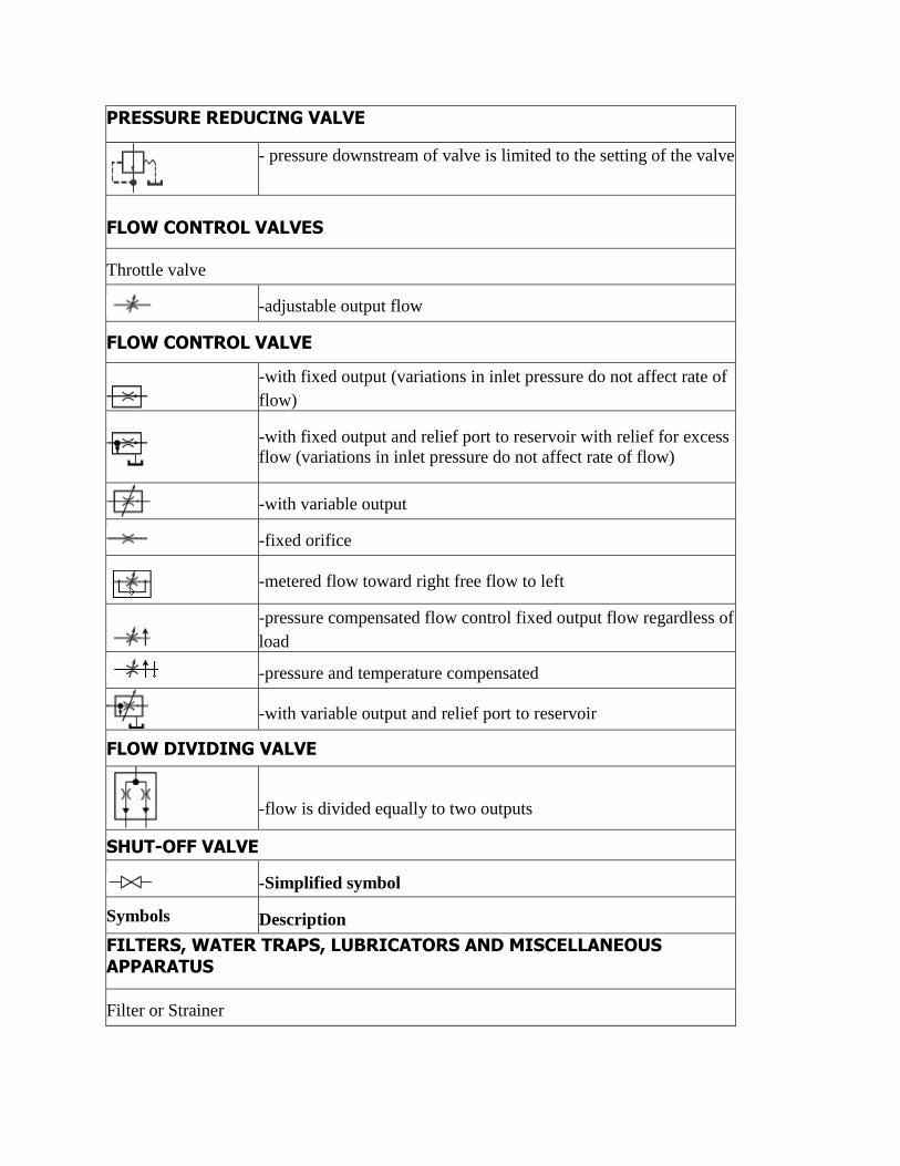
PRESSURE REDUCING VALVE
- pressure downstream of valve is limited to the setting of the valve
FLOW CONTROL VALVES
Throttle valve
-adjustable output flow
FLOW CONTROL VALVE
-with fixed output (variations in inlet pressure do not affect rate of
flow)
-with fixed output and relief port to reservoir with relief for excess
flow (variations in inlet pressure do not affect rate of flow)
-with variable output
-fixed orifice
-metered flow toward right free flow to left
-pressure compensated flow control fixed output flow regardless of
load
-pressure and temperature compensated
-with variable output and relief port to reservoir
FLOW DIVIDING VALVE
-flow is divided equally to two outputs
SHUT-OFF VALVE
-Simplified symbol
Symbols Description
FILTERS, WATER TRAPS, LUBRICATORS AND MISCELLANEOUS APPARATUS
Filter or Strainer
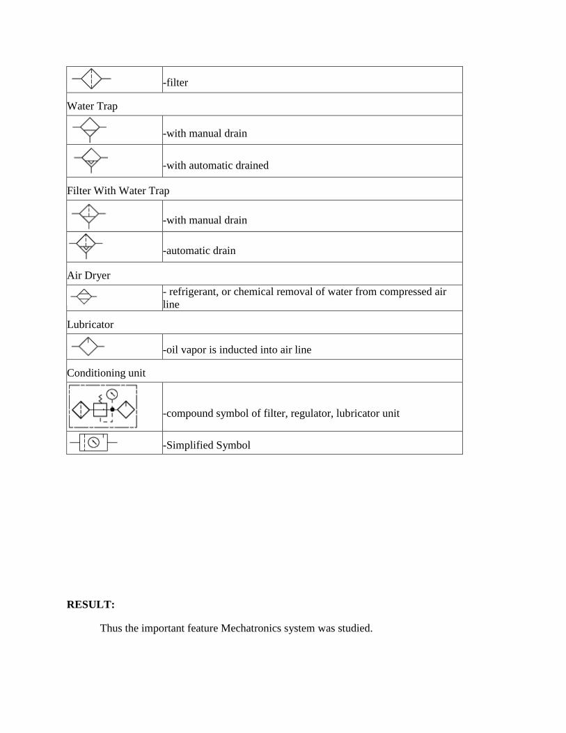
-filter
Water Trap
-with manual drain
-with automatic drained
Filter With Water Trap
-with manual drain
-automatic drain
Air Dryer
- refrigerant, or chemical removal of water from compressed air
line
Lubricator
-oil vapor is inducted into air line
Conditioning unit
-compound symbol of filter, regulator, lubricator unit
-Simplified Symbol
RESULT:
Thus the important feature Mechatronics system was studied.

EX.NO: 02 SIMULATION OF SINGLE ACTING CYLINDER CIRCUIT
DATE:
AIM:
To simulate the single acting cylinder circuit by using AUTOSIM 200 software.
APPARATUS REQUIRED:
1. CPU, Monitor
2. Keyboard and Mouse
3. AUTOSIM 200 Software
PROCEDURE:
1. Autosim software icon is available is the desktop by double clicking the icon.
2. The software home page will open, click new for creating the blank page.
3. Side of the wizard tool is available by using tool use drown the circuit.
4. In the tool symbols, just trag the symbol to the sheet which are the element are necessary
such as (pneumatic –supply element actuator values) compressor, 3/2 mechanically
operated spring controlled direction controlled valve and single acting cylinder.
5. Then correct the ports according to the circuit.
6. Finally simulate by using the simulation tool.
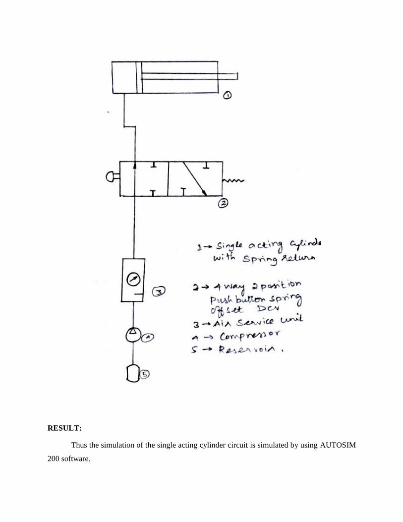
RESULT:
Thus the simulation of the single acting cylinder circuit is simulated by using AUTOSIM
200 software.
EX.NO: 03 SIMULATION OF DOUBLE ACTING CYLINDER CIRCUIT
DATE:
AIM:
To simulate the double acting cylinder circuit by using AUTOSIM 200 software.
APPARATUS REQUIRED:
1. CPU and Monitor
2. Keyboard and Mouse
3. AUTOSIM 200 Software
PROCEDURE:
1. Autosim software icon is available is the desktop by double clicking the icon.
2. The software home page will open, click new for creating the blank page.
3. Side of the wizard tool is available by using tool use drown the circuit.
4. In the tool symbols, just trag the symbol to the sheet which are the element are necessary
such as (pneumatic –supply element actuator values) compressor, 3/2 mechanically
operated spring controlled direction controlled valve and single acting cylinder.
5. Then correct the ports according to the circuit.
6. Finally simulate by using the simulation tool.
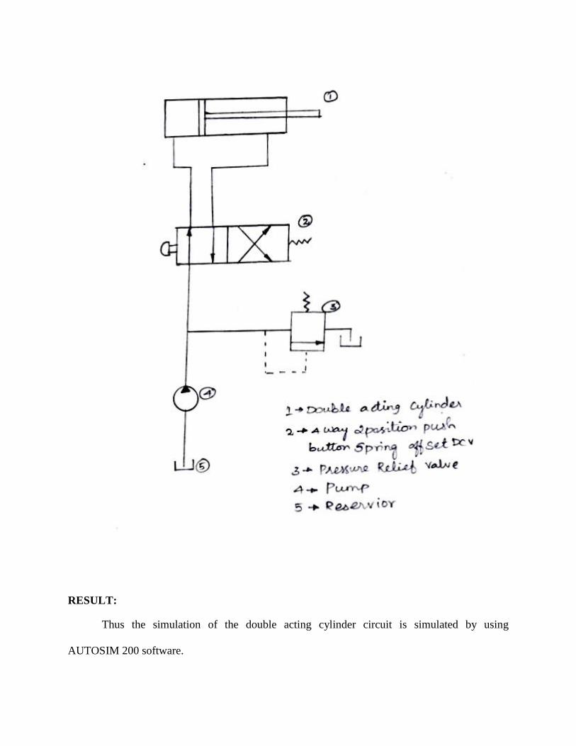
RESULT:
Thus the simulation of the double acting cylinder circuit is simulated by using
AUTOSIM 200 software.
EX.NO: 04 SIMULATION OF SIMPLE HYDRAULIC CIRCUIT
DATE:
AIM:
To simulate the simple hydraulic circuit by using AUTOSIM 200 software.
APPARATUS REQUIRED:
1. CPU and Monitor
2. Keyboard and Mouse
3. AUTOSIM 200 Software
PROCEDURE:
1. Autosim software icon is available is the desktop by double clicking the icon.
2. The software home page will open, click new for creating the blank page.
3. Side of the wizard tool is available by using tool use drown the circuit.
4. In the tool symbols, just trag the symbol to the sheet which are the element are necessary
such as (simple hydraulic circuit –supply element actuator values) compressor, 3/2
mechanically operated spring controlled direction controlled valve and single acting
cylinder.
5. Then correct the ports according to the circuit.
6. Finally simulate by using the simulation tool.
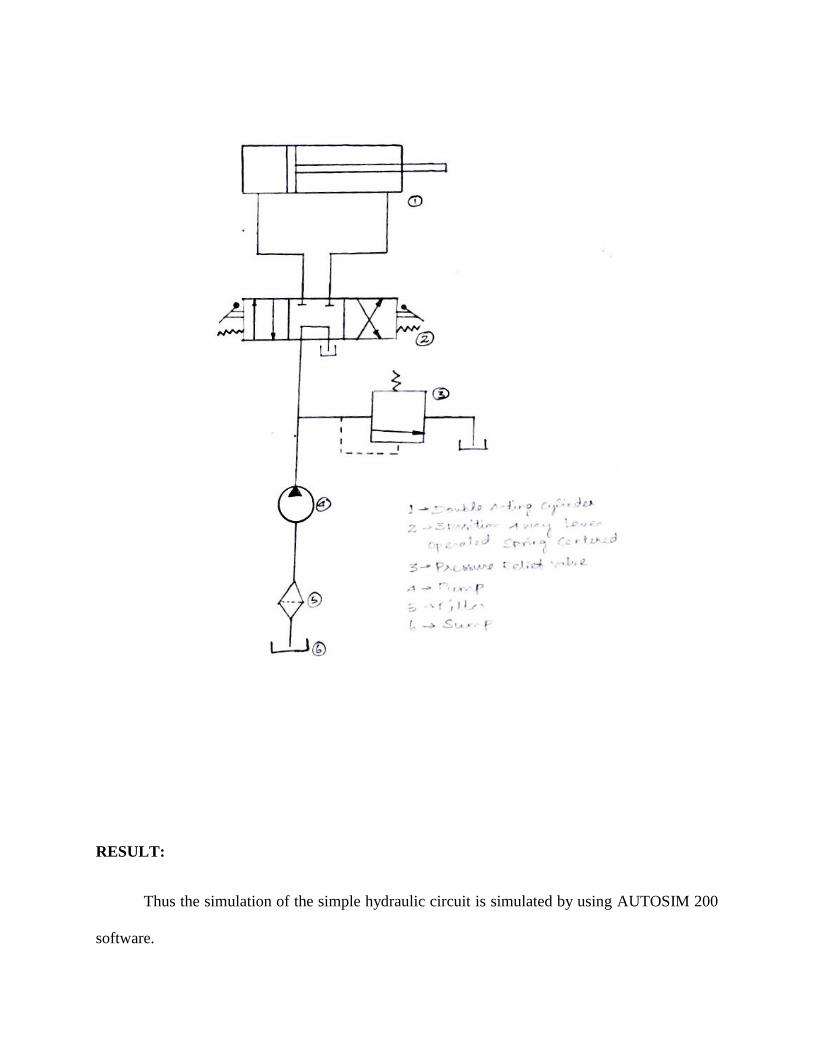
RESULT:
Thus the simulation of the simple hydraulic circuit is simulated by using AUTOSIM 200
software.
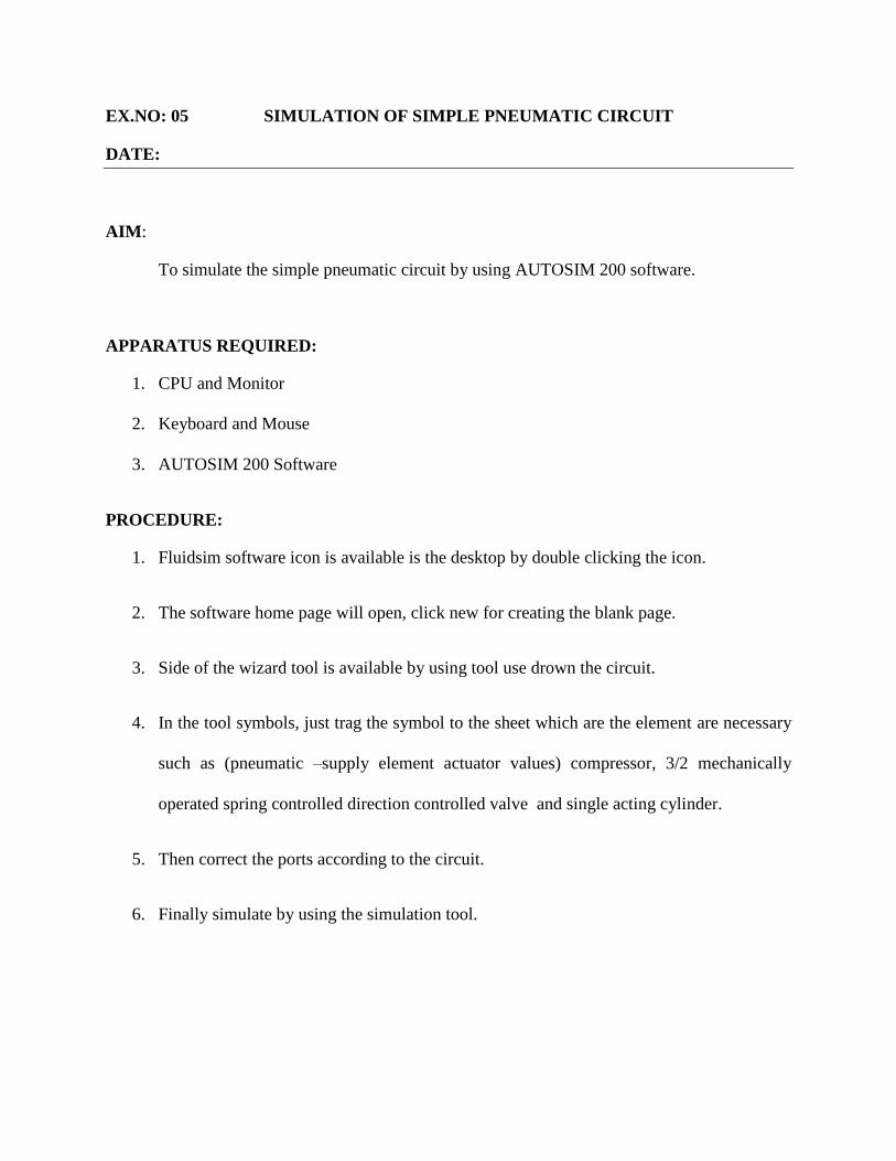
EX.NO: 05 SIMULATION OF SIMPLE PNEUMATIC CIRCUIT
DATE:
AIM:
To simulate the simple pneumatic circuit by using AUTOSIM 200 software.
APPARATUS REQUIRED:
1. CPU and Monitor
2. Keyboard and Mouse
3. AUTOSIM 200 Software
PROCEDURE:
1. Fluidsim software icon is available is the desktop by double clicking the icon.
2. The software home page will open, click new for creating the blank page.
3. Side of the wizard tool is available by using tool use drown the circuit.
4. In the tool symbols, just trag the symbol to the sheet which are the element are necessary
such as (pneumatic –supply element actuator values) compressor, 3/2 mechanically
operated spring controlled direction controlled valve and single acting cylinder.
5. Then correct the ports according to the circuit.
6. Finally simulate by using the simulation tool.
RESULT:
Thus the simulation of the simple pneumatic circuit is simulated by using AUTOSIM 200
software.

EX.NO: 06 SIMULATION OF ELECTRO HYDRAULIC CIRCUIT
DATE:
AIM:
To simulate the electro hydraulic circuit by using AUTOSIM 200 software.
APPARATUS REQUIRED:
1. CPU and Monitor
2. Keyboard and Mouse
3. AUTOSIM 200 Software
PROCEDURE:
1. Autosim software icon is available is the desktop by double clicking the icon.
2. The software home page will open, click new for creating the blank page.
3. Side of the wizard tool is available by using tool use drown the circuit.
4. In the tool symbols, just trag the symbol to the sheet which are the element are necessary
such as (hydraulic –supply element actuator values) compressor, 3/2 mechanically
operated spring controlled direction controlled valve and single acting cylinder.
5. Then correct the ports according to the circuit.
6. Finally simulate by using the simulation tool.

RESULT:
Thus the simulation of the electro hydraulic circuit is simulated by using AUTOSIM 200
software.

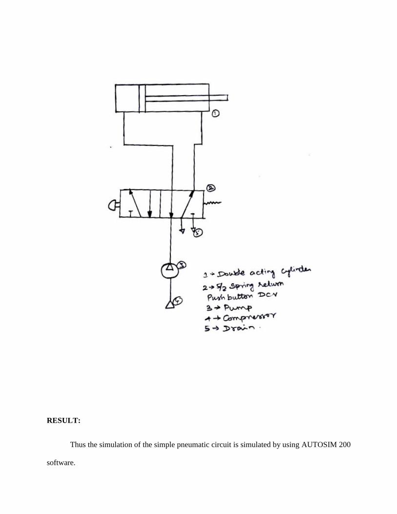
EX.NO: 07 SIMULATION OF ELECTRO PNEUMATIC CIRCUIT
DATE:
AIM:
To simulate the electro pneumatic circuit by using AUTOSIM 200 software.
APPARATUS REQUIRED:
1. CPU and Monitor
2. Keyboard and Mouse
3. AUTOSIM 200 Software
PROCEDURE:
1. Autosim software icon is available is the desktop by double clicking the icon.
2. The software home page will open, click new for creating the blank page.
3. Side of the wizard tool is available by using tool use drown the circuit.
4. In the tool symbols, just trag the symbol to the sheet which are the element are necessary
such as (pneumatic –supply element actuator values) compressor, 3/2 mechanically
operated spring controlled direction controlled valve and single acting cylinder.
5. Then correct the ports according to the circuit.
6. Finally simulate by using the simulation tool.
RESULT:
Thus the simulation of the electro pneumatic circuit is simulated by using AUTOSIM 200
software.
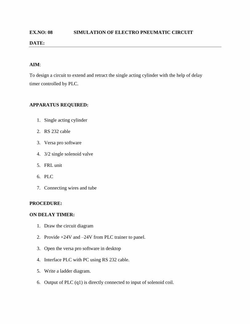
EX.NO: 08 SIMULATION OF ELECTRO PNEUMATIC CIRCUIT
DATE:
AIM:
To design a circuit to extend and retract the single acting cylinder with the help of delay
timer controlled by PLC.
APPARATUS REQUIRED:
1. Single acting cylinder
2. RS 232 cable
3. Versa pro software
4. 3/2 single solenoid valve
5. FRL unit
6. PLC
7. Connecting wires and tube
PROCEDURE:
ON DELAY TIMER:
1. Draw the circuit diagram
2. Provide +24V and –24V from PLC trainer to panel.
3. Open the versa pro software in desktop
4. Interface PLC with PC using RS 232 cable.
5. Write a ladder diagram.
6. Output of PLC (q1) is directly connected to input of solenoid coil.
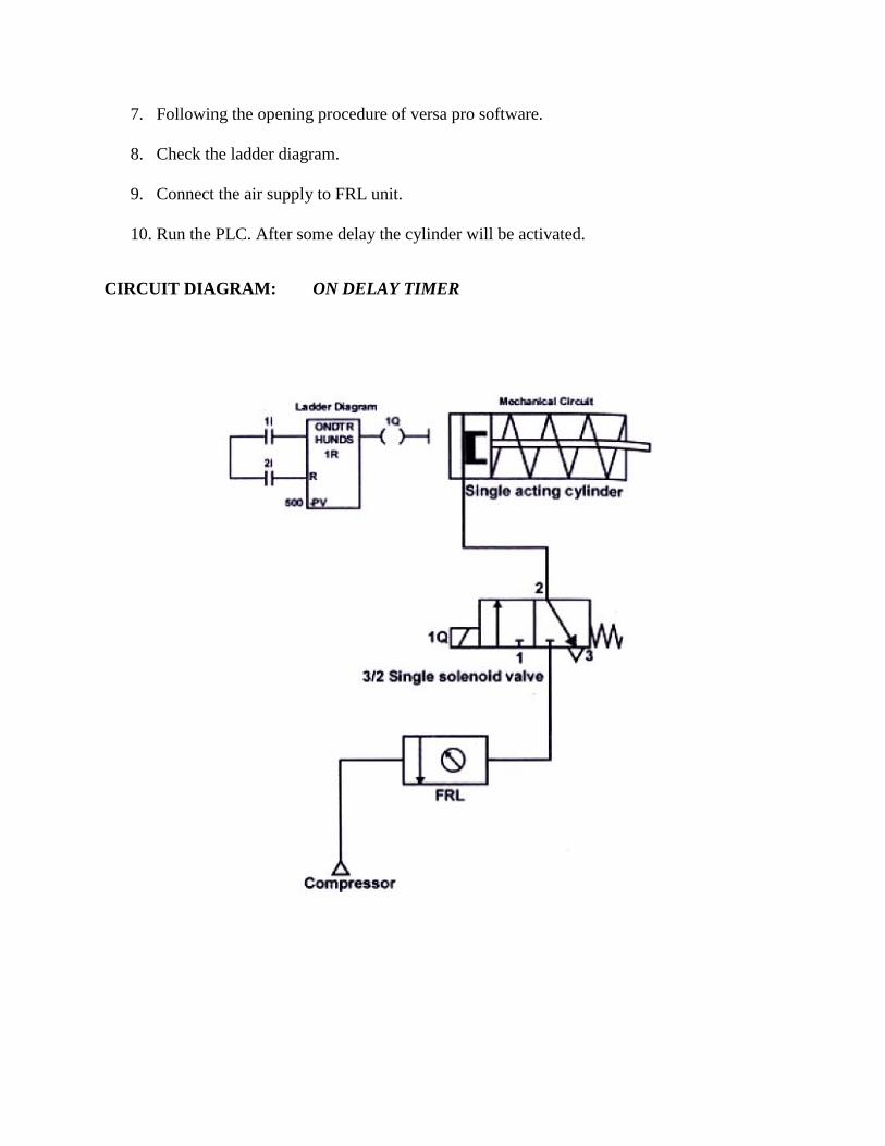
7. Following the opening procedure of versa pro software.
8. Check the ladder diagram.
9. Connect the air supply to FRL unit.
10. Run the PLC. After some delay the cylinder will be activated.
CIRCUIT DIAGRAM: ON DELAY TIMER
PROCEDURE:
OFF DELAY TIMER
1. Draw the circuit diagram
2. Provide +24V and –24V from PLC trainer to panel.
3. Open the versa pro software in desktop
4. Interface PLC with PC using RS 232 cable.
5. Write a ladder diagram.
6. Output of PLC (q1) is directly connected to input of solenoid coil.
7. Following the opening procedure of versa pro software.
8. Check the ladder diagram.
9. Connect the air supply to FRL unit.
10. Run the PLC and observe the working of single acting cylinder.
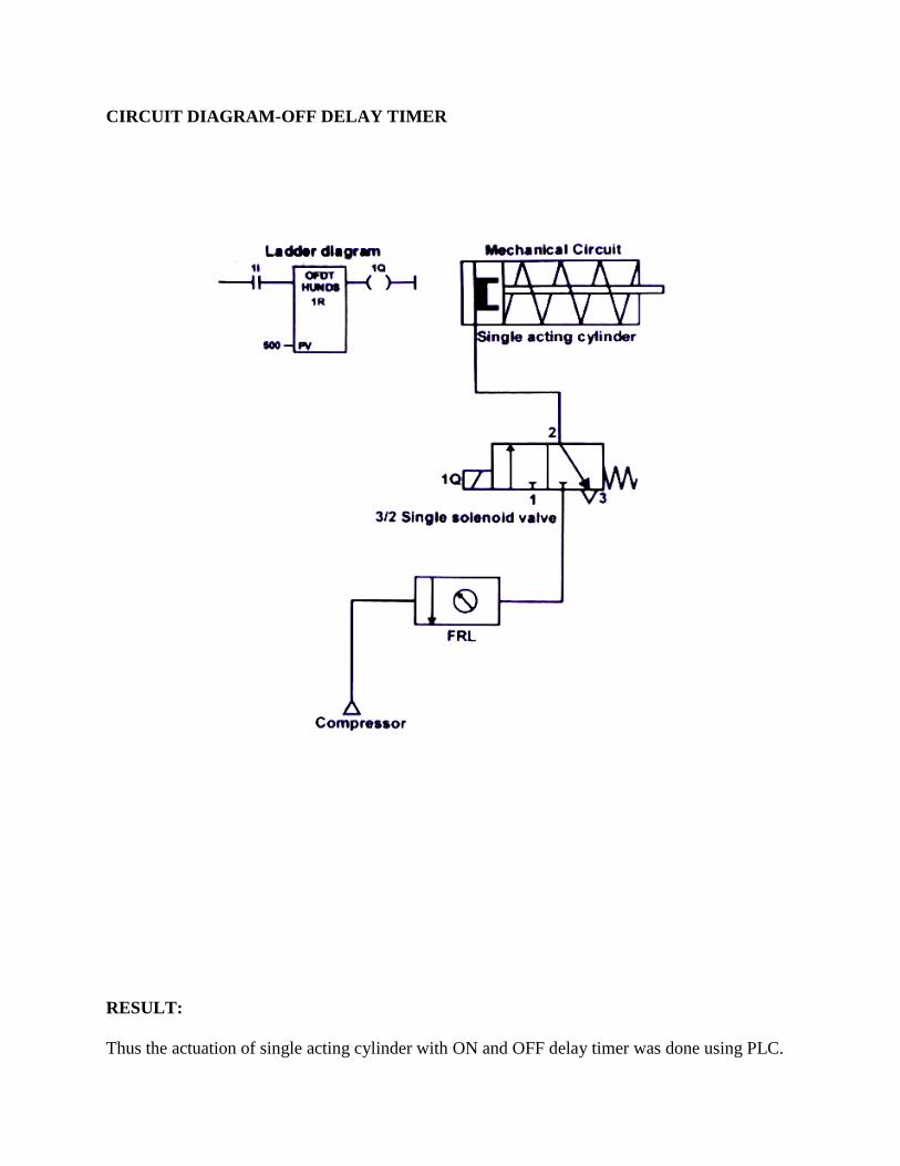
CIRCUIT DIAGRAM-OFF DELAY TIMER
RESULT:
Thus the actuation of single acting cylinder with ON and OFF delay timer was done using PLC.
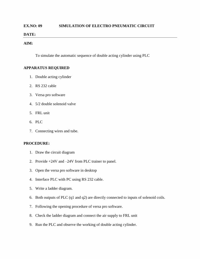
EX.NO: 09 SIMULATION OF ELECTRO PNEUMATIC CIRCUIT
DATE:
AIM:
To simulate the automatic sequence of double acting cylinder using PLC
APPARATUS REQUIRED
1. Double acting cylinder
2. RS 232 cable
3. Versa pro software
4. 5/2 double solenoid valve
5. FRL unit
6. PLC
7. Connecting wires and tube.
PROCEDURE:
1. Draw the circuit diagram
2. Provide +24V and –24V from PLC trainer to panel.
3. Open the versa pro software in desktop
4. Interface PLC with PC using RS 232 cable.
5. Write a ladder diagram.
6. Both outputs of PLC (q1 and q2) are directly connected to inputs of solenoid coils.
7. Following the opening procedure of versa pro software.
8. Check the ladder diagram and connect the air supply to FRL unit
9. Run the PLC and observe the working of double acting cylinder.
CIRCUIT DIAGRAM
RESULT:
Thus the ladder diagram for the automatic running of double acting cylinder is drawn and
executed.
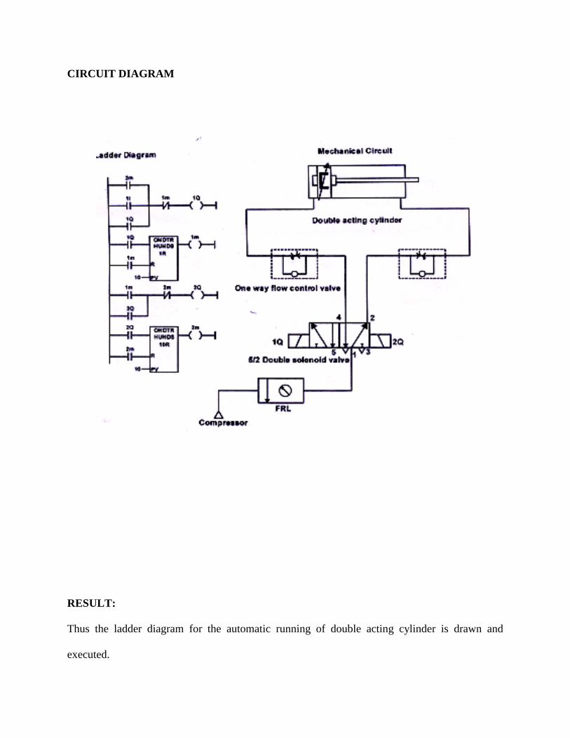
EX.NO: 10 SIMULATION OF ELECTRO PNEUMATIC CIRCUIT
DATE:
AIM:
To design a circuit for the sequence A+B+A-B using PLC.
APPARATUS REQUIRED:
1. Single and double acting cylinder
2. RS 232 cable
3. Versa pro software
4. 3/2 single solenoid valve, 5/2 double solenoid valve
5. FRL unit
6. PLC
7. Connecting wires and tube
PROCEDURE:
1. Draw the circuit diagram
2. Provide +24V and –24V from PLC trainer to panel.
3. Open the versa pro software in desktop
4. Interface PLC with PC using RS 232 cable.
5. Write a ladder diagram.
6. Outputs of PLC (q1, q2, q3 and q4) are directly connected to the inputs of solenoid coil.
7. Following the opening procedure of versa pro software.
8. Check the ladder diagram.
9. Connect the air supply to FRL unit.
10. Run the PLC and observe the working of double acting cylinder.
CIRCUIT DIAGRAM:
RESULT:
Thus the ladder diagram for the automatic running of double acting cylinders is designed and
executed.
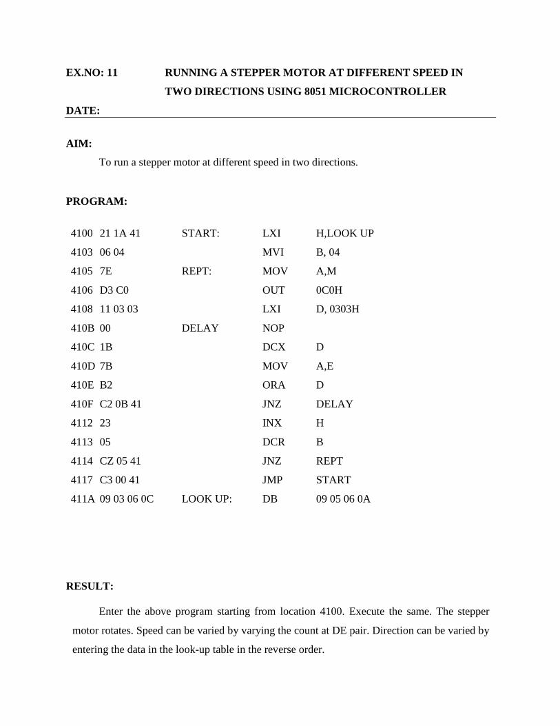
EX.NO: 11 RUNNING A STEPPER MOTOR AT DIFFERENT SPEED IN
TWO DIRECTIONS USING 8051 MICROCONTROLLER
DATE:
AIM:
To run a stepper motor at different speed in two directions.
PROGRAM:
4100 21 1A 41 START: LXI H,LOOK UP
4103 06 04 MVI B, 04
4105 7E REPT: MOV A,M
4106 D3 C0 OUT 0C0H
4108 11 03 03 LXI D, 0303H
410B 00 DELAY NOP
410C 1B DCX D
410D 7B MOV A,E
410E B2 ORA D
410F C2 0B 41 JNZ DELAY
4112 23 INX H
4113 05 DCR B
4114 CZ 05 41 JNZ REPT
4117 C3 00 41 JMP START
411A 09 03 06 0C LOOK UP: DB 09 05 06 0A
RESULT:
Enter the above program starting from location 4100. Execute the same. The stepper
motor rotates. Speed can be varied by varying the count at DE pair. Direction can be varied by
entering the data in the look-up table in the reverse order.
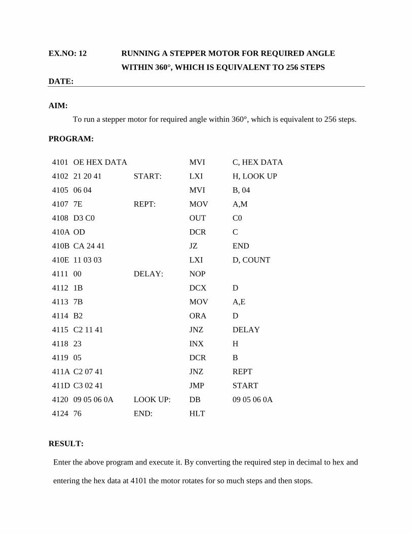
EX.NO: 12 RUNNING A STEPPER MOTOR FOR REQUIRED ANGLE
WITHIN 360°, WHICH IS EQUIVALENT TO 256 STEPS
DATE:
AIM:
To run a stepper motor for required angle within 360°, which is equivalent to 256 steps.
PROGRAM:
4101 OE HEX DATA MVI C, HEX DATA
4102 21 20 41 START: LXI H, LOOK UP
4105 06 04 MVI B, 04
4107 7E REPT: MOV A,M
4108 D3 C0 OUT C0
410A OD DCR C
410B CA 24 41 JZ END
410E 11 03 03 LXI D, COUNT
4111 00 DELAY: NOP
4112 1B DCX D
4113 7B MOV A,E
4114 B2 ORA D
4115 C2 11 41 JNZ DELAY
4118 23 INX H
4119 05 DCR B
411A C2 07 41 JNZ REPT
411D C3 02 41 JMP START
4120 09 05 06 0A LOOK UP: DB 09 05 06 0A
4124 76 END: HLT
RESULT:
Enter the above program and execute it. By converting the required step in decimal to hex and
entering the hex data at 4101 the motor rotates for so much steps and then stops.
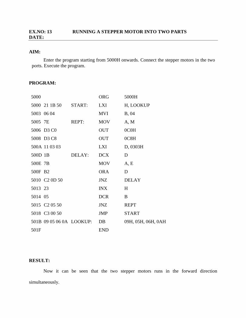
EX.NO: 13 RUNNING A STEPPER MOTOR INTO TWO PARTS
DATE:
AIM:
Enter the program starting from 5000H onwards. Connect the stepper motors in the two
ports. Execute the program.
PROGRAM:
5000 ORG 5000H
5000 21 1B 50 START: LXI H, LOOKUP
5003 06 04 MVI B, 04
5005 7E REPT: MOV A, M
5006 D3 C0 OUT 0C0H
5008 D3 C8 OUT 0C8H
500A 11 03 03 LXI D, 0303H
500D 1B DELAY: DCX D
500E 7B MOV A, E
500F B2 ORA D
5010 C2 0D 50 JNZ DELAY
5013 23 INX H
5014 05 DCR B
5015 C2 05 50 JNZ REPT
5018 C3 00 50 JMP START
501B 09 05 06 0A LOOKUP: DB 09H, 05H, 06H, 0AH
501F END
RESULT:
Now it can be seen that the two stepper motors runs in the forward direction
simultaneously.
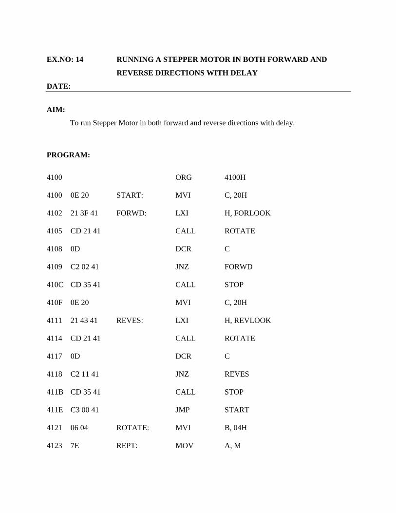
EX.NO: 14 RUNNING A STEPPER MOTOR IN BOTH FORWARD AND
REVERSE DIRECTIONS WITH DELAY
DATE:
AIM:
To run Stepper Motor in both forward and reverse directions with delay.
PROGRAM:
4100 ORG 4100H
4100 0E 20 START: MVI C, 20H
4102 21 3F 41 FORWD: LXI H, FORLOOK
4105 CD 21 41 CALL ROTATE
4108 0D DCR C
4109 C2 02 41 JNZ FORWD
410C CD 35 41 CALL STOP
410F 0E 20 MVI C, 20H
4111 21 43 41 REVES: LXI H, REVLOOK
4114 CD 21 41 CALL ROTATE
4117 0D DCR C
4118 C2 11 41 JNZ REVES
411B CD 35 41 CALL STOP
411E C3 00 41 JMP START
4121 06 04 ROTATE: MVI B, 04H
4123 7E REPT: MOV A, M
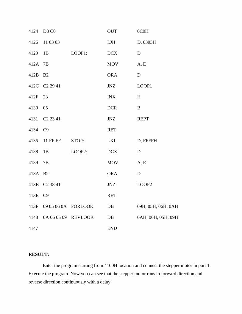
4124 D3 C0 OUT 0C0H
4126 11 03 03 LXI D, 0303H
4129 1B LOOP1: DCX D
412A 7B MOV A, E
412B B2 ORA D
412C C2 29 41 JNZ LOOP1
412F 23 INX H
4130 05 DCR B
4131 C2 23 41 JNZ REPT
4134 C9 RET
4135 11 FF FF STOP: LXI D, FFFFH
4138 1B LOOP2: DCX D
4139 7B MOV A, E
413A B2 ORA D
413B C2 38 41 JNZ LOOP2
413E C9 RET
413F 09 05 06 0A FORLOOK DB 09H, 05H, 06H, 0AH
4143 0A 06 05 09 REVLOOK DB 0AH, 06H, 05H, 09H
4147 END
RESULT:
Enter the program starting from 4100H location and connect the stepper motor in port 1.
Execute the program. Now you can see that the stepper motor runs in forward direction and
reverse direction continuously with a delay.