EFFECTS OF NONUNIFORM SURFACE HEAT FLUX AND ...
25
UCLA/PPG—1046 DE88 011710 EFFECTS OF NONUNIFORM SURFACE HEAT FLUX AND UNIFORM VOLUMETRIC HEATING ON BLANKET DESIGN i?OR FUSION REACTORS Mohammad Z. Hasan "C W PPG-104 6 M a y 1 9 g 8 DISCLAIMER This report was prepared as an account of work sponsored by an agency of the United States Government Neither the United Slates Government nor any agency thereof, nur any of their employees, makes any warranty, express or implied, or assumes any legal liability or responsi- bility for the accuracy, completeness, or usefulness of any information, apparatus, product, or process disclosed, or represents that its use would not infrnge privately owned rights. Refer- ence herein to any specific commercial product, process, or service by trade name, trademark, manufacturer, or otherwise docs not necessarily constitute or imply its endorsement, recom- mendation, or favoring by the United States Government or any agency thereof The views and opinions of authors expressed herein do not necessarily stale or reflect those or the United States Government or any agency thereof. Department of Mechanical, Aerospace, and Nuclear Engineering and Institute for Plasma and Fusion Research University of California, Los Angeles Los Angeles, CA 90024-1597 ,; ."4 iU i Ui. ^
Transcript of EFFECTS OF NONUNIFORM SURFACE HEAT FLUX AND ...
UCLA/PPG—1046 DE88 011710
EFFECTS OF N O N U N I F O R M SURFACE HEAT FLUX AND
UNIFORM VOLUMETRIC HEATING ON BLANKET DESIGN
i?OR FUSION REACTORS Mohammad Z. Hasan
" C W P P G - 1 0 4 6 M a y 1 9 g 8
DISCLAIMER
This report was prepared as an account of work sponsored by an agency of the United States Government Neither the United Slates Government nor any agency thereof, nur any of their employees, makes any warranty, express or implied, or assumes any legal liability or responsibility for the accuracy, completeness, or usefulness of any information, apparatus, product, or process disclosed, or represents that its use would not infrnge privately owned rights. Reference herein to any specific commercial product, process, or service by trade name, trademark, manufacturer, or otherwise docs not necessarily constitute or imply its endorsement, recommendation, or favoring by the United States Government or any agency thereof The views and opinions of authors expressed herein do not necessarily stale or reflect those or the United States Government or any agency thereof.
Depar tment of Mechanical, Aerospace, and Nuclear Engineering and Inst i tute for Plasma and Fusion Research
University of California, Los Angeles Los Angeles, CA 90024-1597 ,; ."4
iU i Ui.
^
E F F E C T S O F N O N U N I F O R M S U R F A C E H E A T F L U X A N D U N I F O R M V O L U M E T R I C H E A T I N G
O N B L A N K E T D E S I G N F O R F U S I O N R E A C T O R S
Mohammad Z. Hasan
Department of Mechanical, Aerospace, and Nuclear Engineering and Institute for Plasma and Fusion Research
University of California, Los Angeles Los Angeles, CA 90024-1597
A B S T R A C T
An analytical solution for ike temperature profile and film temperature drop for fully-developed, laminar flow in a circular tube is provided. The surface heat flux varies circumferentially but is constant, along the axis of the tube. The volumetric heat generation is uniform in the fluid. The fully developed laminar velocity profile is approximated by a power velocity profile to represent the flattening effect of a perpendicular magnetic field when (he coolant is electrically conductive. The presence of volumetric heat generation in the fluid adds another component to the film temperature drop to that due to the surface heat flux. The reduction of the boundary layer thickness by a perpendicular magnetic field reduces both af these two film temperature drops. The Nusselt number far constant surface heat flux increases from 4,36 for parabolic velocity profile to 8 for nearly flat velocity profile or slug flow. The corresponding increase in the Nusselt number for uniform volumetric heat generation is from 2.^6 to 5.33. A strong perpendicular magnetic field can reduce the film temperature drop by a factor of two if the fluid is electrically conducting. The effect of nonuniformity of the surface heat flux, however, is to reduce the Nusselt number or increase the film temperature drop at the location of the maximum heat flux compared to the case of uniform surface heat flux. At the point of maximum surface heat flux with a cosine variation, which is very close to the case of a coolant tube in the first wall and limiter/divert or plate of a fusion reactor, the Nusselt number can be reduced from 4-36 to 2.7 and from 8 to 3 for parabolic and flat velocity profiles, respectively. The effect of perpendicular magnetic field (or the flatness of the velocity profile) is less pronounced on the film temperature drop due to nonuniform surface heat flux than on that due to uniform surface ht-at flux. An example is provided to s/iow the relative effects of these two film temperature drops in the thermal design of fusion reactors.
I . I N T R O D U C T I O N
There are situations where the heat flux on the surface of a coolanl channel
is nonuniform and, at the same time, volumetric heat is generated in the coolant
flowing through a coolant channel. An example of this is a coolant channel in the
first wall and limiter/divertor plate of a fusion reactor. The side of the coolant
channel which faces the plasma receives radiation heat flux. Fusion neutrons
generate volumetric heat in the structural material and coolant. In a fission reactor
using liqiiid fuel, large volumetric heat is generated due to the fission reaction. The
heat is removed through the channel wail and/or by the fuel slurry acting also as the
coolant. Film temperature drop for such a case was determined by Popendiek (lj.
Even with uniform volumetric heat generation, there is a temperature drop across
the boundary layer because fluid velocity is smaller in the boundary layer near the
wall and hence part of the heat needs to be conducted to the central fluid which
then convects away the heat. Reynolds (2j treated the film temperature drop for
the case of nonuniform surface heat flux on a circular tube with parabolic velocity
profile of the fluid.
Liquid metals, particularly liquid lithium, are considered as coolants in fusion
reactor applications. Liquid lithium was proposed as a coolant for fusion reactors
by Holroyd and Mitchell [3] and Hunt and Hancox [4j. A recent reversed-fieid pinch
reactor study, TITAN [5], has used liquid lithium as the primary coolant in one
version of the design of the fusion reactor core. Since liquid metals are electrically
conducting, the presence of any transverse magnetic field will affect the coolant
velocity profile and hence the film temperature drop.
In the thermal-hydraulic design for a fusion reactor, the maximum structure
temperature of a coolant channel is one of the design limits. Accurate determination
of the structure temperature is, therefore, necessary for a safe design. The
film temperature drops directly affect the channel-wall temperature. It is highly
desirable to quantify the effects of magnetic field, volumetric heat generation and
_ •? _
nommiformity of surface heat flux on the film temperature drop for liquid-metal as
well as nonconducting fluid flow through the coolant channel in a fusion reactor.
The objectives of this work are to find analytical estimates for these effects.
The analytical solution uses several assumptions. The coolant channel is taken to
be circular tube. The flow is assumed laminar and fully developed. Power velocity
profile is used to approximate the flattening of the velocity profile by a perpendicular
magnetic field. The magnetic field is transverse to a coolant channel rather than
radial in fusion applications and the channel cross section may be non-circular.
The analytical results will, therefore, be approximate. In section 11, the analytical
solutions are derived. The analytical results and examples of application to fusion
reactors are discussed in section III. Conclusions and recommendations are given in
section IV.
II . T E M P E R A T U R E P R O F I L E A N D F I L M T E M P E R A T U R E D R O P
The steady-state, non-homogeneous energy equation in cylindrical coordinates
(r,0,z) can be written as
where kf is the thermal conductivity of the fluid, T is the temperature, and p
and cp are the density and specific heat of the fluid, respectively. The uniform
volumetric heat generation is denoted by q",' and the fully developed velocity profile
is represented by u(r). It is assumed that the surface heat flux and the volumetric
heafr generation do not vary along the axis of the tube. Therefore, T is a linear
function of the axial coordinate, z. The magnetic field Is assumed to be uniform
and perpendicular to the coolant flow (such as a uniform radial magnetic field). In
this case, the velocity profile will be flattened uniformly along the circumference,
and there will not be any 5-dependence as is the case with a transverse magnetic
field [6j. The velocity profile can then be approximated by the following equation.
- 3 -
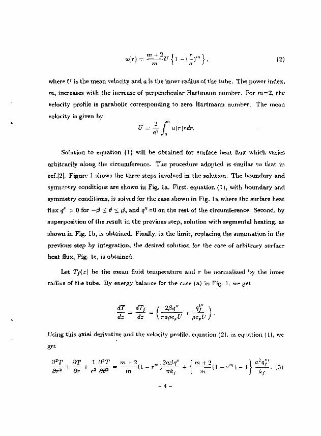
. (r |=^ir{l- |>}, 12) 77! I a >
where U is the mean velocity and a is the inner radius of the tube. The power index,
m, increases with the increase of perpendicular Hartmann number, For m = 2 , the
velocity profile is parabolic corresponding to zero Hart maun number. The mean
velocity is given by 2 f"
U — — / u(r}rdr, a- Jn
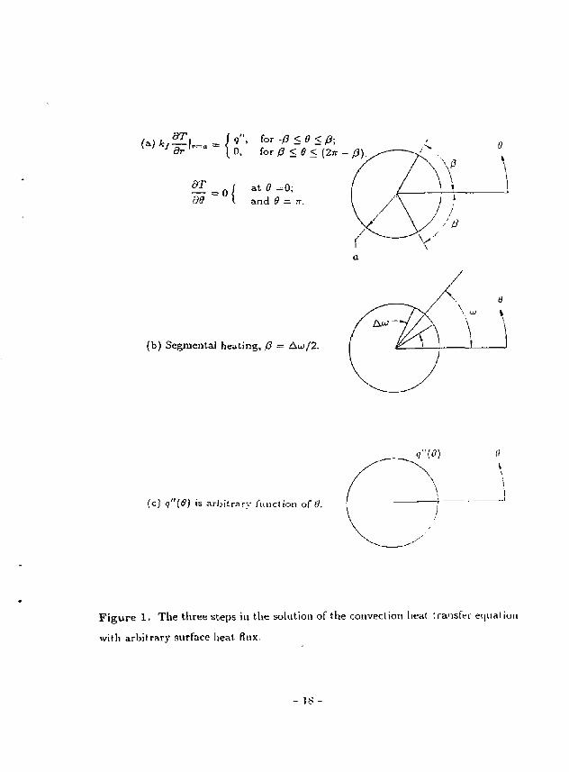
Solution to equation (1) will be obtained for surface heat flux which varies
arbitrarily along the circumference. The procedtire adopted is similar to that in
ref.[2]. Figure 1 shows the three steps involved in the solution. The boundary and
symmetry conditions are shown in Fig. la . First, equation (1), with boundary and
symmetry conditions, is solved for the case shown in Fig. l a where the surface heat
flux q" > 0 for — j3 <B<j3, and <j"=0 on the rest of the circumference. Second, by
superposition of the result in the previous step, solution with segmental heating, as
shown in Fig. l b , is obtained. Finally, in the limit, replacing the summation in the
previous step by integration, the desired solution for the case of arbitrary surface
heat flux, Fig, Ic, is obtained.
Let 2 / ( - ) be the mean fluid temperature and r be normalized by the inner
radius of the tube. By energy balance for the case (a) in Fig. 1, we get
dT dTf / 2j3g" q'J' \ dz dz \ KapcpU pcvU J '
Using this axial derivative and the velocity profile, equation (2), in equation (1), we
get.
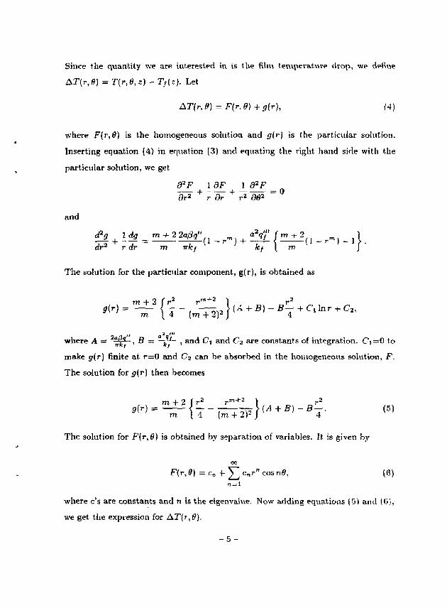
Since the quantity we are interested in is the film temperature drop, we define
A T ( r , e ) = T ( r , 0 , ; ) - T / ( : ) . Let
&Tlr,9) = F(r,0)+g{r), (4)
where F(r,9) is the homogeneous solution and g{r) is (he particular solution.
Inserting equation (4) in equation (3) and equating the right hand side with the
particular solution, we get
d2F 1 9F J L ^ F _ „ dr2 + r 6Y + r^ 902
and
<xrJ r i i r m wfc kf [ m J
The solution for the particular component, g(r), is obtained as
m + 2 ( V r m + 3 } r2
a HI
where A = a \ i , fl = fe * , and Ct and (?2 are constants of integration. C'i=0 to
make </(r) finite at r = 0 and Cj can be absorbed in the homogeneous solution, F.
The solution for g(r) then becomes
The solution for F(T%0) is obtained by separation of variables. It is given by
oo
F(r,9) = c„ + ^ C T i r " cosn0, (6)
where c's are constants and n is the eigenvalue. Now adding equations (5) and (6),
we get the expression for AT(rtff),
- 5 -
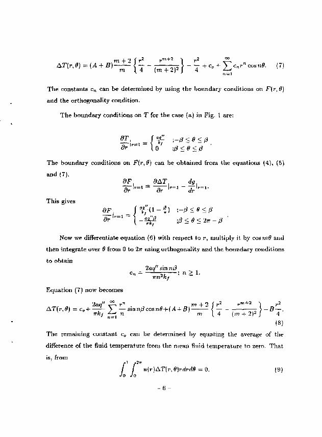
m + 2 f r 2 r m + 2 ) r 2 ™
The constants c n can be determined by using the boundary conditions on F(r , 6)
and the orthogonality condition.
The boundary conditions on T for the case (a) in Fig, 1 are:
2Ii ={'-£ ;-tfsff d r l r ~ l I o ;i3<e<
8F dAT dg
r _ 1 1 - ^ ; / ? < ^ < 2 T T - / 3
The boundary conditions on F(r,$) can be obtained from the equations (4), (5)
and (7).
This gives
Now we differentiate equation (6) with respect to r, multiply it by cosm9 and
then integrate over 6 from 0 to 2tr using orthogonality and the boundary conditions
to obtain 2aq" sin nj3
c n = 57 ; n>l. Tm-'kf
Equation (7) now becomes
2aq" P,rn m + 2 [ r 2 r m + 2 ) r2
AT(r,9) = ca + -^Y-Sinnl3co5n£ + {A + B) - - — — = } - B - . Trkf *-^ n m I 4 (n> + 2)2 J 4
(8)
The remaining constant ca can be determined by equating the average of the
difference of the fluid temperature from the mean fluid temperature to zero. Tha t
is, from
I i u(r) <ST(r, €)rdrd.9 = 0. (9) Jo Jo

From equation (9), using equations (2) and {8), cB is obtained as
, D = _ { A + B ) f + 6 : + i 2 + Bim+2)(m+3)
' S ( m + 4 ) ( m + 2) 2m|m + 4)
The film temperature drop, A!T/(0), is obtained by putting r = l in equation (8) and
using the expressions for c„, A and B. This gives
ATf(0) = -— I r—^ ,„ I + -: > - r s u m p cos n.0 ; fc/7T \ 8 m 2 + 48m + 64 / fc/7r ^ n 2
a 2 ? / " / 3 m 3 + 26m 2 + 68m + 48 + kf \ Sm3 + 4 8 m 3 + 64m J *
Now if the heat flux is only on a small segment of the surface of the tube as
shown in case (b) of Fig. 1, the film temperature drop due to this small segmental
heat flux, 5T/(0), can be obtained by replacing /? by Aw/2 and <? by (0 — w — Aw/2)
in equation (10). Thus we obtain
c r F . . . 2aq" Aw / m 2 + 10m + 20 \ 2aq" ^ 1 . rcAu> 6 T } { 9 ) = ~ * 7 ^ U m 2 + 4 S m + 64 / ) + T^ ^ rf S ' U ~
n = l (11) Aw, aq",' / 3 m 3 + 26m 2 + 68m + 48 \
c o s „ ( ^ w _ T ) + 1 - J 8m3 + 48m 2 + 64m J "
If there are L small segments with surface heat flux, then the total film temperature
drop can be obtained by superposition of the result in equation (11)-L
A7>(«9) = £ > A 7 > ( 0 ) . (12)
The summation is only over the first two terms in equation (11). For the case of
continuous variation of surface heat flux, case (c) in Fig. 1, the film temperature
drop can be obtained by replacing Y ^ = , by J^* Aw and approximating sin —^ by
ndu>/2 in equation (11) and (12). Doing this, we get
A ^ ,m a ( m2 + IQm + 20 \ f2n a f2* ,. %
A ™^U* + 48m + 6 4 U 9 M d - ^ y o < M
, , . B - w . , a2q'i' / 3 m 3 + 26m 2 + 68m + 48 \ lm2s in — — \dui ~——— I — ]
x 2 ' kf V 8m3 + 48m 2 + 64m /
(13)
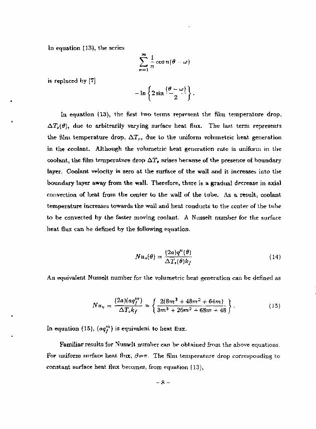
In equation (13), the series °° 1
E — cosn[Q — u>) n
7 1 = 1
is replaced by [7]
In equation (13), the first two terras represent the film temperature drop,
ATj,(0), due to arbitrarily varying surface heat flux. The last term represents
the film temperature drop, AT^, due to the uniform volumetric heat generation
in the coolant. Although the volumetric heat generation rate is uniform in the
coolant, the film temperature drop AT„ arises because of the presence of boundary
layer. Coolant velocity is zero at the surface of the wall and it increases into the
boundary layer away from the wall. Therefore, there is a gradual decrease in axial
convection of heat from the center to the wall of the tube. As a result, coolant
temperature increases towards the wall and heat conducts to the center of the tube
to be convected by the faster moving coolant. A Nusselt number for the surface
heat flux can be defined by the following equation.
An equivalent Nusselt number for the volumetric heat generation can be defined as
N u _ ( 2 a ) ( q ? / f ) = ( 2(8m3 + 48m2 + 64m) ) U" ~ &T„kf ~ \ 3 m 3 + 26m 2 + 68m + 48 J '
In equation (15), (aq'l1) is equivalent to heat flux.
Familiar results for Nusselt number can be obtained from the above equations.
For uniform surface heat flux, l3=n. The film temperature drop corresponding to
constant surface heat flux becomes, from equation (13),
- 8 -
A T = ^ L / m 2 + 10m + 20 \
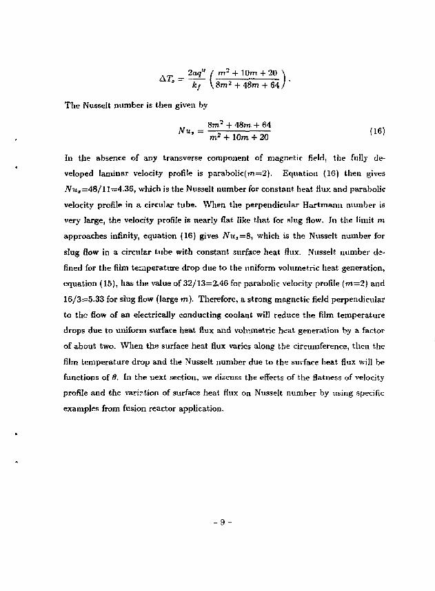
The Nusselt number is then given by
8m- + 48m + 64 Nu, = (16)
m* + 10m + 20
In the absence of any transverse component of magnetic field, the fully de
veloped laminar velocity profile is parabolic(m=2). Equation (16) then gives
Nu, =48/11=4.36, which is the Nusselt number for constant, heat flux and parabolic
velocity profile in a circular tube. When the perpendicular Hartmanii number is
very large, the velocity profile is nearly flat like that for slug flow. In the limit m
approaches infinity, equation (16) gives Nua=8, which is the Nusselt number for
slug flow in a circular tube with constant surface heat flux. Nusselt number de
fined for the film temperature drop due to the uniform volumetric heat generation,
equation (15), has the value of 32/13=2.46 for parabolic velocity profile (m=2) and
16/3=5.33 for slug flow (large m). Therefore, a strong magnetic field perpendicular
to the flow of an electrically conducting coolant will reduce the film temperature
drops due to uniform surface heat flux and volumetric heat generation by a factor
of about two. When the surface heat flux varies along the circumference, then the
film temperature drop and the Nusselt number due to the surface heat flux will be
functions of 9. In the next section, we discuss the effects of the flatness of velocity
profile and the variation of surface heat flux on Nusselt number by using specific
examples from fusion reactor application.
9 -
I I I . R E S U L T S A N D D I S C U S S I O N
Coolant channels with circular cross sections are often used in fusion reactor
thermal-hydraulic design because circular tubes have good hest transfer perfor
mance, high structural strength, and are easy to manufacture with close toler
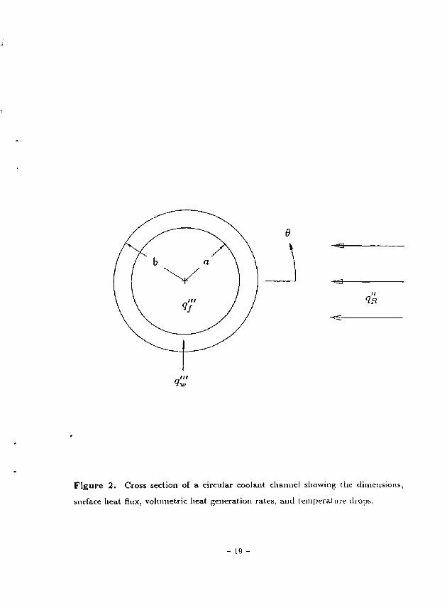
ance [5]. Figure 2 shows the cross section of a first-wall coolant tube used in the
thermal-hydraulic design of the fusion power core of the reversed-field-pinch fusion
reactor, TITAN-1 [5]. The tube material is the vanadium alloy, V-3Ti-lSi, and the
coolant is liquid lithium. The inner radius of the tube is 4 mm and its outer radius
is 5.05 turn. The radiation heat flux incident on the surface of the first-wall tube
facing the plasma is denoted by qjj and the volumetric nuclear heat generation rates
in the tube wall and lithium are represented by ijj,',' and q'f, respectively. Neutron
wall loading of TITAN-[ is 18.1 MWfm2. The nuclear heat generation at the first
wall are q'^ ~ 100 MW/m3 and q'" ~ 75 MW/m1. At the design point where 95%
of the alpha and ohmic dissipative power in the plasma is radiated, tlw radiation
heat flux on the first wall is 4.6 MW/rrr. At different wall loading or different
radiation fraction, the heat flux on the first wall will have different values. The ef
fects of nonuniformity of the sirface heat flux and the flatness of the velocity profile
caused by perpendicular magnetic field, on heat transfer will be presented in this
section. The first-wall coolant channel of TITAN-I will be used as example.
The surface heat flux on the urn- r surface ol a first-wall tube can be written as
^• W = {*»+!#«»» -J4i-J (17) (9NK ?3 S V S T",
where
q N H ~ 2a '
The outer radius of the coolant channel is b. Equation (17) assumes that the
radiation heat flux is cosine on the tube surface and that conduction in the tu?je
wall along 9 is negligible.
- 10 -
The total film temperature drop due to nonuniform surface heat flux and
uniform volumetric heat generation is given by equation (13). Eq*iations (15)
and (16) determine the Nusselt numbers for uniform volumetric heat generation in
the coolant and constant surface heat flux, respectively, as functions of the paver
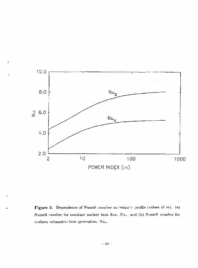
index [m) of the velocity profile. Figure 3 shows this variation. At m = 2 , for
parabolic profile, Nu, =48 /11 due to constant surface heat flux and iVy„=32/13
due to uniform volumetric heat generation. As m increases, NIL approaches the
slug-flow magnitudes of 8 and 16/3 for the uniform surface heat flux and volumetric
heat generation, respectively. This shows that whenever a perpendicular magnetic
field flattens the velocity profile, thus reducing the boundary layer thickness, heat .
transfer will become better and film temperature drop will decrease.
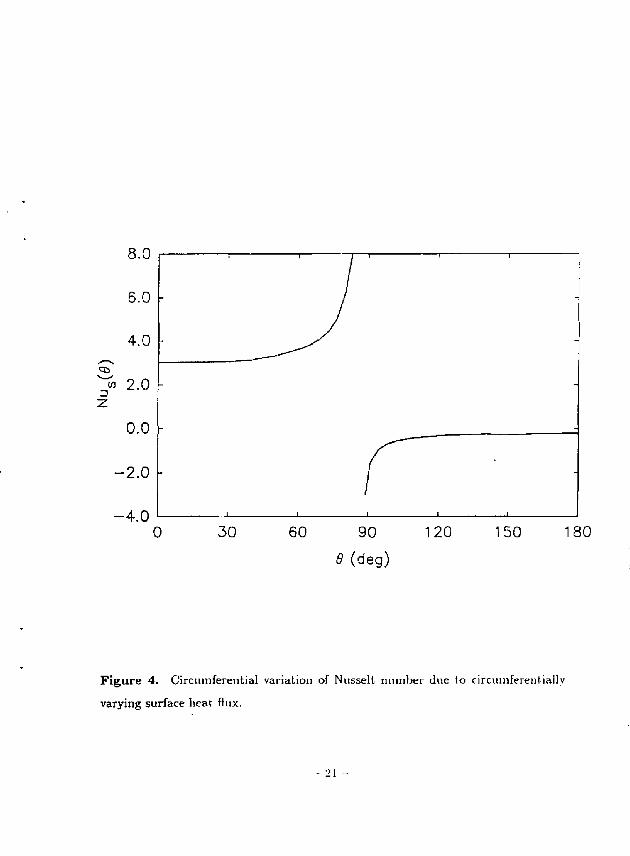
The effect of circumferential variation of surface heat flux is shown in Fig. 4.
The value of m is 250 which gives nearly slug flow corresponding to high perpen
dicular Hartmann number (> 200). The surface heat flux is given by equation (17)
with 9 R = 4 . 6 MWjm2 and q£=100 M W / m 3 . The tube dimensions are the same
as those for the first-wall tube for T1TAN-I. The Nusselt number is the smallest at
0=0" where the radiation heat flux is the maximum. The value of Nusselt num
ber at 0=0° is about 3. It is much less than 8 for constant heat flux. At about
85°, Nu becomes infinite. The reason is that at this point the wall/coolant in
terface temperature becomes equal to the mean coolant temperature thus making
the film temperature drop zero. Beyond this point, Nu is negative. Negative Nus-
selt number means that the mean coolant temperature is higher than the interface
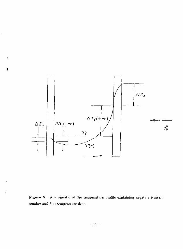
temperature so that the film temperature drop becomes negative. A schematic rep
resentation of the temperature profile which explains this is shown in Fig. 5. When
the Nusselt number is negative, the magnitude of the film temperature drop has to
be subtracted from the mean fluid temperature to obtain the temperature at the
inner surface of the wall of the coolant tube.
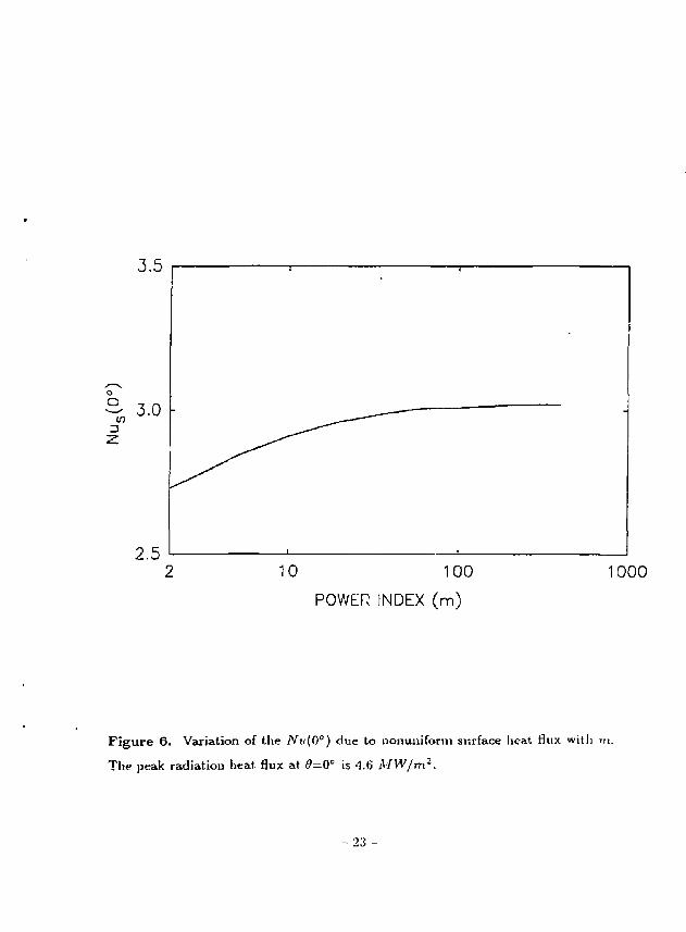
Figure 6 shows the variation of Nu with m at 0=0 and peak radiation heat flux
- 1 1 -
of 5^=4.6 MW/m2. The uniform heat flux at the inner surface of the tube due to
volumetric heat generation in the tube wall, gjv/f, is 0.145 MWfm?. This is about
32 times smaller than the peak radiation heat flux at 0=0. Under this condition
of highly peaked surface heat flux, the increase in Nu in going from parabolic to
nearly flat velocity profile is very small, only 10% (2.7 to 3.0) compared to about
85% (4.36 to 8) increase for the case of constant heat flux. This means that when
the surface heat flux is highly peaked, perpendicular magnetic field, however large,
does increase very little the Nu at the critical point of peak heat flux, that is, at
0=0" under the present condition. This will have significant impact on the thermal-
hydraulic design of the first wall, divertor and limiter of a fusion reactor using liquid
metal as coolant.
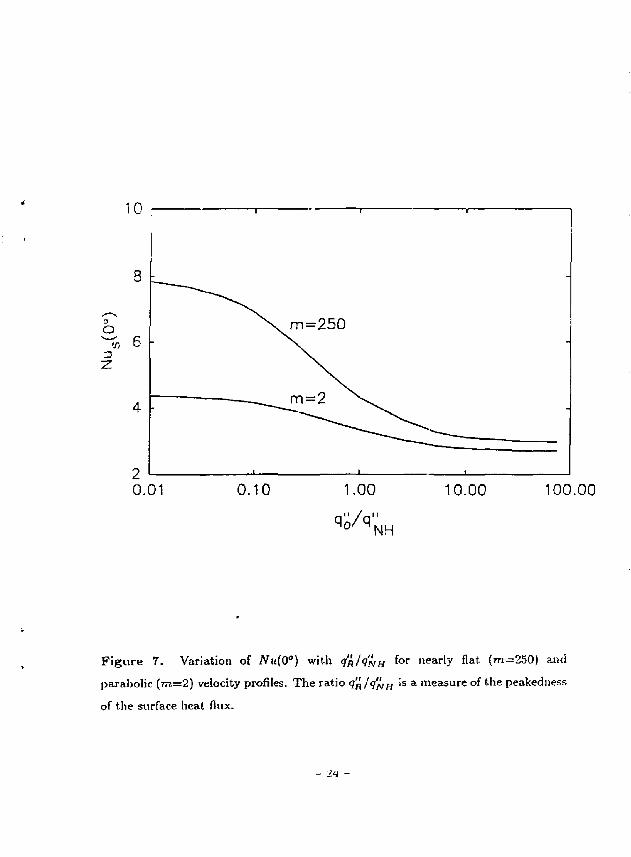
The effects of peakedness of the surface heat flux on the Nusselt number for
parabolic (m=2) and nearly flat (m=250) velocity profiles are shown in Fig. 7. In
this figure, Nu(0=O") is plotted against q'n/q'liH- ' ^ u e Ta^T> q'jt/q'hii is a measure
of the peakedness of the surface heat flux. The heat flux at the inner surface of
the tube wall due to the nuclear heating in the wall, q'^ff, is constant along the
circumference. The peak radiation heat flux, q'^ , is varied to change the ratio. The
curve for m = 2 5 0 simulates the flattening of the velocity profile of a conducting fluid
b j a perpendicular magnetic field. At q'ft/q'wn=(i< JVu=8, the case for constant heat
flux and slug flow. The Nusselt number at 0=0° decreases rapidly with the increase
of he ratio q'ti/q'^u- At q'k.'q'piH^^i ^ u ^ ' s t o a b o u t 3 and remains almost
constant with further increase of peakedness of the surface heat flux. Therefore, the
more peaked the surface heat flux is, the less effective becomes the perpendicular
magnetic field in increasing the heat transfer.
In Fig. 7, the curve for m=2 shows that at <7^/<?JV/J=0, Nit—A.ZQ which is the
Nusselt number for parabolic velocity profile and constant surface heat flux. With
the increase of the ratio q'^/q'^H, the Nusselt number decreases and reaches a value
of 2.7 for highly peaked surface heat flux. It can be noted that for parabolic velocity
- 1 2 -
profile, the effect of peakedness of the surface heat flux in reducing the Nusselt
number is less pronounced compared to that for nearly flat velocity profile (m—250),
The maximum reduction of Nu for parabolic velocity profile is about 37%, whereas
it is about 62% for nearly flat velocity profile. Another point that should be noted is
that , when the surface heat flux is highly peaked, the difference between the Nusselt
numbers for parabolic velocity profile and nearly slug flow is small, about 10% (2.7
compared to 3). This signifies that the nominiformity of the surface heat flux is
more effective in reducing the Nusselt number or increasing the film temperature
drop in the presence of a perpendicular magnetic field than in the absence of it
(parabolic profile).
In the thermal-hydraulic and structural design of the first wall, Umiter/divertor
plates and blanket of a fusion reactor, the effects of nonuniformity of surface heat
flux, volumetric heat generation in the coolant, and perpendicular magnetic field
can be significant and should be included for a safe design. As an example of these
effects, we can look at the various film temperature drops for laminar flow in the
first-wall coolant tube of TITAN-I. The surface heat flux and the volumetric heat
generation rates in the wall material and coolant are as mentione'j above. At the
point of maximum surface heat flux, 9 — 0°, the film temperature drops are 317°C
for parabolic profile and 278° C for nearly flat profile. If the effect of nonuniformity
of the surface heat flux is neglected, these two film temperature drops would become
196°C and 104°C, respectively. The amount of underestimation is quite large. The
film temperature drops due to volumetric heat generation are 2l°C for parabolic
profile and 9.7°C for nearly flat profile. This temperature drop, which appears not
to be included in fusion design, can be quite large for coolants with low thermal
conductivity such as FLiBe.
- 1 3 -
I V . C O N C L U S I O N S A N D R E C O M M E N D A T I O N S
The effects of nonuniform surface heat flux, uniform volumetric heat generation
and velocity profile on the film temperature drop in fully developed laminar flow in
a circular tube are discussed by deriving an analytical solution. The velocity profile
of the coolant is represented • by a power law which can be used to represent the
flattening of the profile by a perpendicular magnetic field if the coolant is electrically
conducting. The following conclusions can be drawn from this analysis.
1. The flattening of velocity profile increases the heat transfer through a reduction
of the thickness of the boundary layer. With constant surface heat flux, the
Nusselt number increases by 83% (from 48/11 to 8) from parabolic to nearly
flat velocity profile. The Nusselt number corresponding to uniform volumetric
heat generation, defined by equation (15), increases by 117% (from 32/13 to
16/5).
2. The nonuniformity of surface heat flux decreases the Nusselt number at the
point of maximum heat flux. With the increase of peakedness of the surface
heat flux according to equation (IT), the Nusselt number decreases from 4.36
to 2.7 for parabolic velocity profile, and from 8 to 3 for nearly slug flow.
3. The point (2) above infers that the effect of nonuniformity of the surface heat
flux is more pronounced for flat velocity profile than for parabolic profile.
Therefore, the heat transfer in liquid-metal coolant in the presence of a
perpendicular magnetic field in a fusion reactor will be significantly affected
by the nonuniformity of the surface heat flux.
The results obtained in this paper have significant implications for the design
of coolant channels for the removal of thermal energy from the first wall, Hm-
iter/divertor plates, and blanket of a fusion reactor. The surface heat flux varies
along the circumference of the coolant channels for the first wall and divertor/limiter
plates due to the incidence of radiation from the plasma. The maximum wall tem
peratures of the coolant channels for the first wall and divertor/Iimiter plates will
- 1 4 -
be severely underestimated if the effect of nonuniformity of the surface heat flux is
not taken into account. This is particularly important when the surface heat flux is
high and th-2 coolant is electrically conducting so that the velocity profile becomes
nearly flat due to the effect of a large perpendicular magnetic field.
It appears that the component of the film temperature drop due to uniform
volumetric heat generation in the coolant is not accounted for in the design of the
coolant channels for fusion reactors, in a deuter ium/tr i t ium fueled fusion reactor,
significant amount of volumetiic heat will ks generated in the coolant if it is not
transparent to the fusion neutrons. In this case, the film temperature drop due to
the volumetric heat generation must be added to obtain the total film temperature
drop and to determine the correct channel-'wall temperature. For liquid-metal
coolants, this film temperature drop may not be large because of the high thermal
conductivity of the coolant. On the other hand, if the thermal conductivity of
a coolant is low and the volumetric heat generation rate is appreciable, this film
temperature drop can be quite large.
The analysis done in this paper is applicable to fully developed laminar flow
only. Similar analysis should be done for turbulent flow since the coolant, flow
is expected to be both laminar and turbulent in the coolant channels in different
components of a fusion reactor. Although the magnitudes of these film temperature
drops for turbulent flow may be different from those for laminar flow, the trend is
expected to be the same.
A c k n o w l e d g e m e n t : This work was supported by the U.S. D.O.E. grant DE-FG03-
86ER52126.
- 1 5 -
REFERENCES
1. H. F . Popendiek, "Forced Convection Heat Transfer in Pipes with Volume-Source within the Fluid", Chem. Eng. Progr. Symposium Ser., vol. 50, No. 11, (1954), pp-93-104.
2. W. C. Reynolds, J. Heat Transfer, Trans. ASME 82 (2) (196), ppl08-112.
3. J. H. Holroyd and J. T. M. Mitchell, "Liquid Lithium as a Coolant for Tokamak Fusion Reactors' 1 , Culham Lab. Report CLM-R231 (1982).
4. J. C. R. Hunt and R. Hancox, "The Use of Liquid Lithium as Coolant in a Toroidal Fusion Reactor", Culham Lab. Report (1971).
5. F . Najmabadi et al, , "The TITAN Reversed-Field-Pinch Fusion Reactor Study— Final Report", UCLA-PPG-1200 (1988).
6. R. R. Gold, Magnetohydrodynamic pipe flow, Part I, J. Fluid Mech. 13 (1962) pp 505-512.
7. K. Knopp, "Theorie und Anwendung der Unendlichen Reihen", Verlag Von Julius Springer, Berlin (1924), p-378.
- 1 6 -
F I G U R E C A P T I O N S :
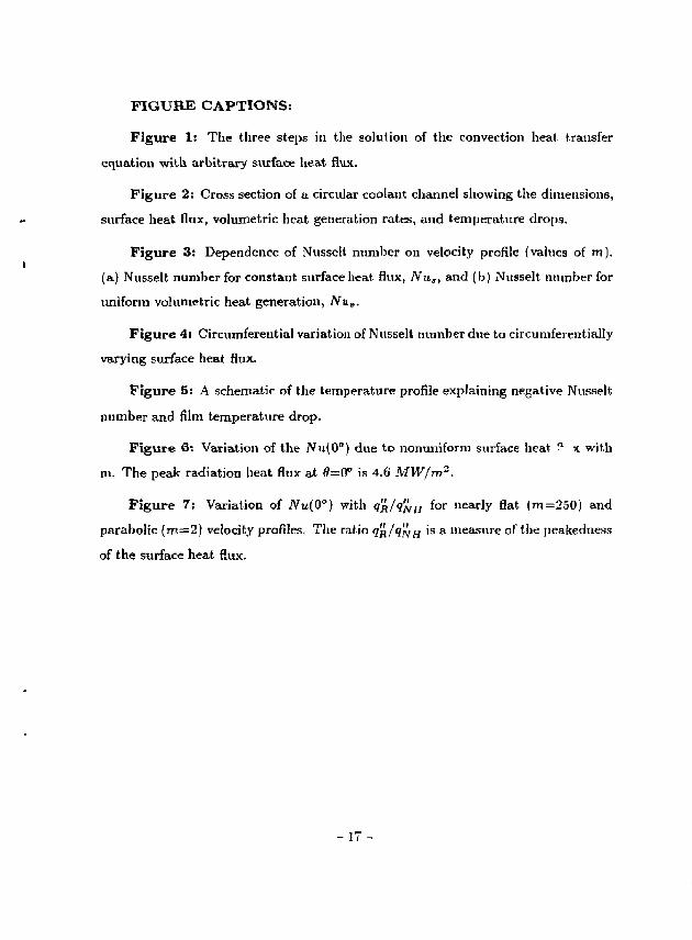
Figure 1: The three steps in the solution of the convection heat transfer
equation with arbitrary surface heat flux.
Figure 2 : Cross section of a circular coolant channel showing the dimensions,
surface heat flux, volumetric heat generation rates, and temperature drops.
Figure 3: Dependence of Nusselt number on velocity profile (values of m).
(a) Nusselt number for constant surface heat flux, Nu,, and (b) Nusselt number for
uniform volumetric heat generation, Nuv,
Figure 4: Circumferential variation of Nusselt number due to circumferentially
varying surface heat flux.
Figure 5: A schematic of the temperature profile explaining negative Nusselt
number and film temperature drop.
Figure 6: Variation of the yVu(0°) due to nonuniform surface heat " x with
m. The peak radiation heat flux at 0=0° is 4.6 MW/m2.
Figure 7: Variation of JV^O") with q'jt/q'rjH f o r l l e a r l y flat (m=250) and
parabolic (m=2) velocity profiles, The ratio <?R/<?JVH ' S a measure of the peakedness
of the surface heat flux.
- 1 7 -
(a) A , — I ~h"< <™-P<0<P\ (aj A r ^ | P = B ^ | o > for ^ < ff s ( 2 ; r _
— - o / at 0 =0; 50 ~" I and 9 = ir.
(b) Segmental heating, j3 = A U J / 2 .
(c) <?"(£) is arbitrary function off?.
F i g u r e 1. The three steps in the solution of the convection heat transfer equation
with arbitrary surface heat flux.
- IS -
-*sa-
<2H
Figure 2 . Cross section of a circular coolant channel showing the dimensions,
surface heat flux, volumetric heat generation rates, and temperature drops.
- 19 -
10.0
^ 6.0 -
2.0 10 100
POWER INDEX (m)
1000
Figure 3 . Dependence of Nnsselt number on veloci'y profile (values of m). (a)
Nusselt number for constant surface beat Hiix, Nu,. and (b) Nusselt number for
uniform volumetric beat generation, ,'Vn,..
- 20
8.0
6.0
4.0
<n n 2.0
0.0
-2 .0
-4 .0
- ' /
! 1
- _^y -
1 1
-
-
L 1 1 ' l
0 30 60 90 120
9 (deg)
150 180
Figure 4. Circumferential variation of Nusselt number due lo circuinferentially
varying surface beat flux.
- 21 -
AT*,
- S 3 -
?*
Figure 5. A schematic of the temperature profile explaining negative Nusselt
number and film temperature drop.
O CO
3
2.5 10 100
POWER INDEX (m) 1000
Figure 6. Variation of the Nit(0°) due to nonuniform surface heat flux with m.
The peak radiation heat flux at 0=0° is 4.6 MW/m2.
- 23 -
0.01 0.10 1.00
qJi/q":
10.00 100.00
NH
F i g u r e 7. Variation of JV«(0°) with qk/q'^H for nearly flat (m=250) and
parabolic (m=2) velocity profiles. The ratio q'^/q'^H Is a measure of the peakedness
of the surface heat flux.
- m