Ecole d'électronique numérique - Fréjus, 25 au 30 … · Ecole d'électronique numérique -...
74
R. Jacobsson Ecole d'électronique numérique - Fréjus, 25 au 30 novembre 2012 1
Transcript of Ecole d'électronique numérique - Fréjus, 25 au 30 … · Ecole d'électronique numérique -...

R. Jacobsson Ecole d'électronique numérique - Fréjus, 25 au 30 novembre 2012 1

R. Jacobsson Ecole d'électronique numérique - Fréjus, 25 au 30 novembre 2012
Personal view – 20 year of experience with DELPHI & LHCb • Physicist view…. • Unavoidably a bias in the examples and in the opinions • First three years of LHCb operation + two shifters and 96% operational efficiency
From physics idea to PCB and back
How the global specifications determine the choice and design of each
component
A long list of global requirements/concepts in order to commissioning and operate and maintain detector which has to be kept in mind when developing even the lowest chip
• Common traps and missed points
Beam time is expensive + competition is tough Collection of concepts to keep in mind
2
R. Jacobsson Ecole d'électronique numérique - Fréjus, 25 au 30 novembre 2012
1. Introduction • Setting the scope • Rates at collider experiments
2. Basic concepts • Multi-level trigger systems and readout
structures 3. Front-end electronics
• General architecture • Digitizers • Signal processing
4. Trigger principles and implementations • Setting the scope • Trigger basics • Trigger design and performance • Fast and synchronous hardware triggers • Software triggers
5. Experiment timing • Timing and fast control systems
3
6. Event readout • Readout networks (buses, switches, etc) • Event building and online farm processing (event
filters) • Data storage
7. Configuration, control and monitoring • Operating modes • Run control • Data monitoring and quality control
8. Conclusions
Data Acquisition Systems • Front-end Readout • Event Building
Run Control • Tools and Architecture

R. Jacobsson Ecole d'électronique numérique - Fréjus, 25 au 30 novembre 2012 4
Architectural requirements
Hardware constraints
Technology Studies
System & Component Specs
R&D & design
Design Readiness Review
Design & Prototyping
Production
Installation
Commissioning
Operation & Maintenance
Upgrade
Production Readiness Review
Validation
Readout Requirements
Trigger Requirements
Detector requirements
Simulation
Physics question
Decide about the question to answer before the technology (and the money)
== Fundamental Research
nm
cm
m
10m
1026m

R. Jacobsson Ecole d'électronique numérique - Fréjus, 25 au 30 novembre 2012 5
Architectural requirements
Hardware constraints
Technology Studies
System & Component Specs
R&D & design
Design Readiness Review
Design & Prototyping
Production
Installation
Commissioning
Operation & Maintenance
Upgrade
Production Readiness Review
Validation
Readout Requirements
Trigger Requirements
Detector requirements
Simulation
Physics question The success of the “global” phase is vitally linked to the development phase: “An experiment is as good as its smallest component”

R. Jacobsson Ecole d'électronique numérique - Fréjus, 25 au 30 novembre 2012 6
Architectural requirements
Hardware constraints
Technology Studies
System & Component Specs
R&D & design
Design Readiness Review
Design & Prototyping
Production
Installation
Commissioning
Operation & Maintenance
Upgrade
Production Readiness Review
Validation
Readout Requirements
Trigger Requirements
Detector requirements
Simulation
Physics question
The software (control and monitoring) phase [should] go hand in hand with the hardware phase already from start

R. Jacobsson Ecole d'électronique numérique - Fréjus, 25 au 30 novembre 2012
Physics Detector Trigger Readout
7
Event rate : ~ 109 Hz Event selection : ~ 1/1013

R. Jacobsson Ecole d'électronique numérique - Fréjus, 25 au 30 novembre 2012
8

R. Jacobsson Ecole d'électronique numérique - Fréjus, 25 au 30 novembre 2012 9
Detector & trigger
simulation Reconstruction & analysis
Feedback
Physics results
Data acquisition
system
Trigger system Signals Decisions
Raw data Mass storage
Detector
Clock
Accelerator
Readout control system
Info Control
Experiment Control System
Detector Safety System
Experiment Control System = HV, LV, motion, readout configuration, data taking control, monitoring, etc

R. Jacobsson Ecole d'électronique numérique - Fréjus, 25 au 30 novembre 2012
10
ADC
Sensor
Processing
Pipelined Trigger
Clock
Storage
Busy logic
FIFO
DataReady
Timing BX
Accept/Reject
Beam crossing
Full
Analog Pipeline
Front-end pipelines Trigger decision processing + transmission delays are
longer than beam crossing period
Timing Trigger Front-end pipelines Derandomizer buffers Busy logic Deadtime/efficiency Parallel processing (Event building)
“Real time”….

R. Jacobsson Ecole d'électronique numérique - Fréjus, 25 au 30 novembre 2012 11 11 11
Amplifier
Filter
Shaper
Range compression
clock Sampling
Digital filter
Zero suppression
Buffer
Formatting & Readout
Buffer
Feature extraction
Detector
Ana
log
Dig
ital
Clock distribution in an experiment is critical
Lim (Digital) fclock∞ = Analog

R. Jacobsson Ecole d'électronique numérique - Fréjus, 25 au 30 novembre 2012
Precise Front-End strategy is defined by the detector technology
A wide variety of technologies for four purposes: • Tracking & momentum measurement • Identification • Energy measurement
Analog readout / digital readout / binary readout
ADC / TDC
12

R. Jacobsson Ecole d'électronique numérique - Fréjus, 25 au 30 novembre 2012
Which are the challenges at each level of the readout system? Defines to a large extent the organization, technology, design of components and links
• Radiation • Mechanical stress (vibrations and cables and busses) • Magnetic field • Distance/spread • Size and material budget • Accessibility • EMI (noise) • EMI immunity • Power • Heat dissipation • Cooling • Flexibility • Clock quality • Buffering • Bandwidth • Operational logic • Computational performance • Control and monitoring requirements • Reliability • Availability / fault tolerance • Cost • Redundancy • Autonomy • Partitioning

R. Jacobsson Ecole d'électronique numérique - Fréjus, 25 au 30 novembre 2012
Which are the challenges at each level of the system? Defines to a large extent the organization, technology, design of components and links
• Radiation / SEU immunity • Mechanical stress (vibrations and cables and busses) • Magnetic field • Distance/spread • Accessibility • Size and material budget • EMI (noise) • EMI immunity • Power • Heat dissipation • Cooling • Flexibility • Clock quality • Buffering • Bandwidth • Operational logic • Computational performance • Control and monitoring requirements • Reliability • Availability / fault tolerance • Cost • Redundancy • Autonomy • Partitioning

R. Jacobsson Ecole d'électronique numérique - Fréjus, 25 au 30 novembre 2012
Example of vertex detector FE: Custom integrated circuits essential for vertex detectors in HEP.
Requirements
• 1. low mass to reduce scattering • 2. low noise • 3. fast response • 4. low power • 5. radiation tolerance • Powering is typically located far from FE, voltage drop, high current etc…
Conflicts and compromises
• reduction in mass thin detector • radiation tolerance thin detector • thin detector less signal lower noise required • lower noise increased power • fast response increased power • increased power more mass in cabling + cooling • immunity to external pickup shielding mass • + contain costs
15

R. Jacobsson Ecole d'électronique numérique - Fréjus, 25 au 30 novembre 2012
Which are the challenges at each level of the system? Defines to a large extent the organization, technology, design of components and links
• Radiation • Mechanical stress (vibrations and cables and busses) • Magnetic field • Distance/spread • Accessibility • Size and material budget • EMI (noise) • EMI immunity • Power • Heat dissipation • Cooling • Flexibility • Clock quality • Buffering • Bandwidth • Operational logic • Computational performance • Control and monitoring requirements • Reliability • Availability • Cost • Redundancy • Autonomy • Partitioning

R. Jacobsson Ecole d'électronique numérique - Fréjus, 25 au 30 novembre 2012
20
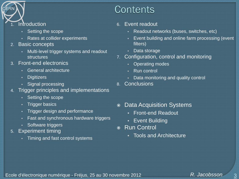
Detector Channels (FE)
Readout Electronics
Readout Network
Processing/Filtering
Storage
Trigger
Con
trol a
nd M
onito
ring
Timing and Readout Control
Detector sense wires

R. Jacobsson Ecole d'électronique numérique - Fréjus, 25 au 30 novembre 2012
21
Detector Channels (FE)
Readout Electronics
Readout Network
Processing/Filtering
Storage
Trigger
Con
trol a
nd M
onito
ring
Timing and Readout Control
50 –
100
m
50 – 100m
~100
m
~100
m
0 - 10m
Detector sense wires 0 – few meters
50 –
100
m
50 – 100m 50 – 100m
R. Jacobsson Ecole d'électronique numérique - Fréjus, 25 au 30 novembre 2012
22
Detector Channels (FE)
Readout Electronics
Readout Network
Processing/Filtering
Storage
Trigger
Con
trol a
nd M
onito
ring
Timing and Readout Control
Detector sense wires
Com
mer
cial
C
usto
m

R. Jacobsson Ecole d'électronique numérique - Fréjus, 25 au 30 novembre 2012
23

R. Jacobsson Ecole d'électronique numérique - Fréjus, 25 au 30 novembre 2012
Links between Front End – Readout Boards • Custom based (radiation)
Links between the custom hardware (ROB) and commercial hardware • Commercial large scale networks for the event building and interface to processing farm
24
DDL Optical 200 MB/s ≈ 400 links Full duplex: Controls FE (commands, Pedestals, Calibration data) Receiver card interfaces to PC
SLINK Optical: 160 MB/s ≈ 1600 Links Receiver card interfaces to PC.
SLINK 64
LVDS: 200 MB/s (max. 15m) ≈ 500 links Peak throughput 400 MB/s to absorb fluctuations Receiver card interfaces to commercial NIC (Myrinet)
Glink (GOL) Optical 200 MB/s ≈ 400 links Receiver card interfaces to custom-built Ethernet NIC (4 x 1 Gbit/s over copper)

R. Jacobsson Ecole d'électronique numérique - Fréjus, 25 au 30 novembre 2012
Sensors
Front-End Electronics
Aggregation (Zero suppression
Aggregation/ (Zero Suppression
Zero Suppression Data Formatting/ Data Buffering
Event Building Network
Processing Farm
Perm. Storage
On/
near
Det
ecto
r O
ff D
etec
tor
Front-End Electronics
Front-End Electronics
Front-End Electronics
Front-End Electronics
R. Jacobsson Ecole d'électronique numérique - Fréjus, 25 au 30 novembre 2012
26
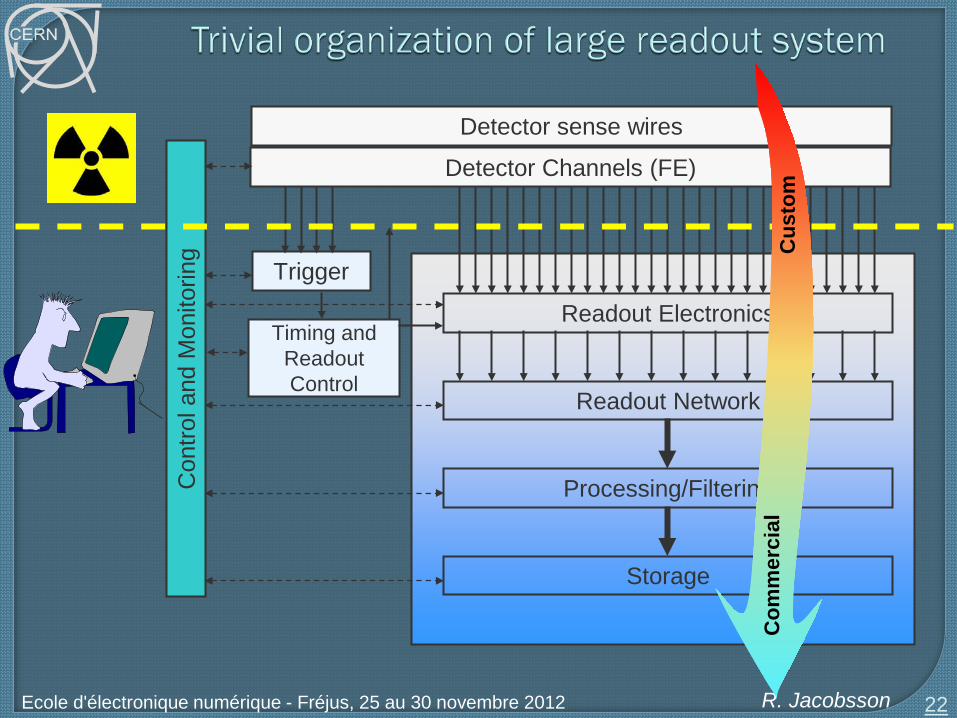
40 MHz
100 kHz – 1 MHz
1 - 40 kHz ~ 1-100 Gbytes/s
Rate
100 Hz ~ 1- 100 Mbytes/s
Detector channels 106 - 108
Event builder
Readout
MUX-ADC-DERANDOMIZERS
MUX-ADC DERANDOMIZER
DSP
CPU
CPU
CPU
CPU
CPU
CPU
CPU
CPU
CPU
Digital buffer 10 – 60000 evts
Analog pipeline 100 – 1000 evts
Data links (100 – 1000)
L1 trigger (1-10 µs)
L2 trigger (10 µs - ms)
L2/L3 trigger (Event filter)
Front-End

R. Jacobsson Ecole d'électronique numérique - Fréjus, 25 au 30 novembre 2012
27
LHC
• LHC ATLAS CMS LHCb ALICE (Pb + Pb)
106 – 108 electronics channels
LEP : e+e- crossing rate 45 kHz
22 µs
SPS : pp crossing rate 260 kHz
3.8 µs
96 ns
Tevatron : pp crossing rate 2.5 MHz
396 ns HERA : ep crossing rate 10.4 MHz
LHC : pp crossing rate 40 MHz
0.5 ns
CLIC : e+e- crossing rate 2 GHz (pulsed)! 25 ns
R. Jacobsson Ecole d'électronique numérique - Fréjus, 25 au 30 novembre 2012
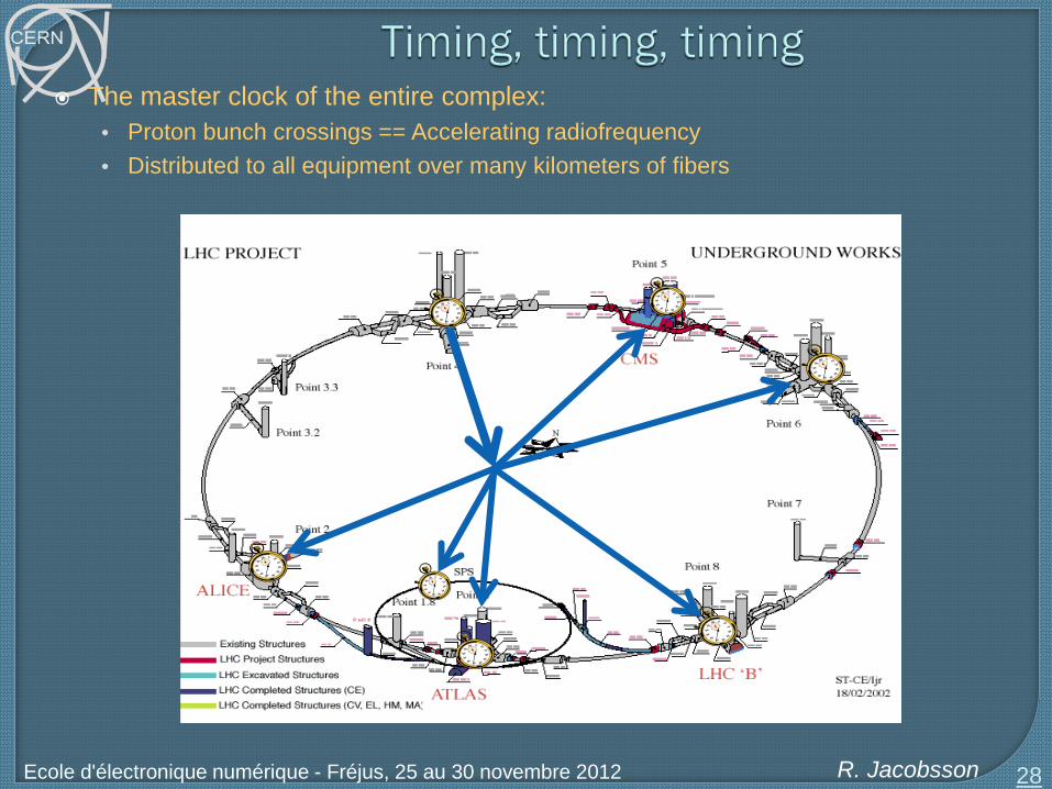
The master clock of the entire complex: • Proton bunch crossings == Accelerating radiofrequency • Distributed to all equipment over many kilometers of fibers
28

R. Jacobsson Ecole d'électronique numérique - Fréjus, 25 au 30 novembre 2012
Key points • Experiment requires a global clock receiver interfaced to the timing distribution in the
experiment Should be able to adjust the global phase of the experiment Presence and stability of the clocks must be monitored locally
• The accelerator clock(s) are the global master clocks of the entire readout system Sampling the detector signal at the optimal point at the FE Sample the fast readout control commands Drive the operational logic Drive the data links The phase between the clock and the bunch arrival time must be monitored locally
• All stages of clock distribution must respect Reproducible and locally controllable fine phase(O(100ps)) Reproducible and locally controllable transmission delay / latency (clock cycles) Low jitter Local quartz-based PLL circuits are generally needed to clean-up clocks
• Ultimate set up of all phase adjustments and latencies with beam and consecutive forced
sampling of bunch crossings (“timing scans”)
29

R. Jacobsson Ecole d'électronique numérique - Fréjus, 25 au 30 novembre 2012
! Watch acceptance range of PLL circuits!! Affected by environment Should include the entire energy range of the beam (injection flat top)
30
fclock
Accel.
Nominal PLL range Shifted PLL range
Jitter
Desynchronization
Clock and network are blamed for everything that goes wrong…!

R. Jacobsson Ecole d'électronique numérique - Fréjus, 25 au 30 novembre 2012
Data transport and local processing is a relatively “simple” task • Similar challenges in any development • But in a HEP experiment it is far from a local task, i.e. stand-alone The challenge is the global functioning with a maximum of intact, calibrated, good data
Fundamental additional tasks of the readout electronics • Timing • Synchronization • Event (data) rejection based on trigger decision • Calibration and special triggers • “Special readout modes” • Throttling ( = detecting and signaling overflow situation) • Truncation • Data destination assignment • Monitoring • Fault detection • Error recovery All of these tasks has to follow a coordinated behavior
Synchronization is the task of ensuring that the data fragments belonging to the same bunch crossing is treated the same way and that they all carry the same identifier in order to be structured together before storage
• Heartbeat, counters and sequenced resets in synch with accelerator 31

R. Jacobsson Ecole d'électronique numérique - Fréjus, 25 au 30 novembre 2012
The additional fundamental tasks driven by a central “readout controller” • In many experiments, this is associated with the central first level trigger • However, trigger is just another subsystem which produces the physics decision Only one - expensive set of links with FE
• Readout controllers needs to be flexible, modifiable, redundant, reliable etc
Readout control commands needed by FE, BE (readout boards) and farm • Synchronous distribution
Adjustable delays on each command at Front-End
• Timing aligning with time-of-flight, signal cable length, processing times
32

R. Jacobsson Ecole d'électronique numérique - Fréjus, 25 au 30 novembre 2012
33
Readout Supervisor
LHC accelerator Beam Phase and Intensity Monitor
Subdetectors
Event Filter Farm
L0 trigger
RS Event Bank
Events Requests
Bunch currents Clock/orbit,UTC, LHC Parameters
HW and run parameters
Run statistics Luminosity
Detector status
L0 Decision
RO Electronics
Trigger Throttle
FE Electronics
Readout control Information exchange
Luminosity

R. Jacobsson Ecole d'électronique numérique - Fréjus, 25 au 30 novembre 2012
Readout control Common specifications! • FE is custom electronics • Often ASIC = carved in stone • Needs a common behavior • High speed control
Detector channel
Readout system
Timing, trigger and fast control
Trigger throttling
Trigger link

R. Jacobsson Ecole d'électronique numérique - Fréjus, 25 au 30 novembre 2012
Rate reduction at FE or complete FE readout • Allows more time and more advanced event selection with a full software trigger
35

R. Jacobsson Ecole d'électronique numérique - Fréjus, 25 au 30 novembre 2012
Partitioning • Possibility of operating a part of the detector autonomously with its own powering,
configuration, triggering scheme, and readout independently from all other parts of the detector.
Implication on infrastructure and architecture Control and readout slices
List of use cases • Installation phase • Commissioning phase • Testing and debugging • Stand-alone calibrations • Problem solving during data taking
Partitioning is different from masking • Disabling a part of the system which causes problems to readout, trigger, event
processing • System should allow masking at any level and configure the appropriate dependencies
(automatically) in the rest of the system chain
36

R. Jacobsson Ecole d'électronique numérique - Fréjus, 25 au 30 novembre 2012
Partitioning the DAQ imposes strong constraints in the software and hardware. Some resources are shareable and some not
One or several readout slices together makes a partition
Implications on control • The control and monitoring should respect the same borders
37
Digitizers Readout Units
Event Building
Event Filter
Storage
Detector Channels
Event filter
Event builder
Readout slice A B C A trigger source (local trigger or trigger supervisor)
A set of readout units (data sources) attached to the detector parts to be run
Some bandwidth on the event building.
Processing resources.
Data storage.
R. Jacobsson Ecole d'électronique numérique - Fréjus, 25 au 30 novembre 2012
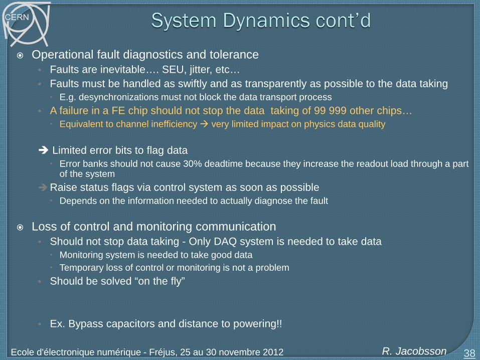
Operational fault diagnostics and tolerance • Faults are inevitable…. SEU, jitter, etc… • Faults must be handled as swiftly and as transparently as possible to the data taking E.g. desynchronizations must not block the data transport process
• A failure in a FE chip should not stop the data taking of 99 999 other chips… Equivalent to channel inefficiency very limited impact on physics data quality
Limited error bits to flag data Error banks should not cause 30% deadtime because they increase the readout load through a part
of the system Raise status flags via control system as soon as possible Depends on the information needed to actually diagnose the fault
Loss of control and monitoring communication • Should not stop data taking - Only DAQ system is needed to take data Monitoring system is needed to take good data Temporary loss of control or monitoring is not a problem
• Should be solved “on the fly”
• Ex. Bypass capacitors and distance to powering!!
38

R. Jacobsson Ecole d'électronique numérique - Fréjus, 25 au 30 novembre 2012
Dynamic system design
39
Global synchronization and trigger signals
TTC controllerTTC controller
TTC controllerGlobal TTC controller
TTC switch/Fan-out
TTC driverPartition 1
TTC driverPartition N
Global synchronization and trigger signals
LocalTTC controller
LocalTTC controller
LocalTTC controller
LocalTTC controller
LocalTTC controller
LocalTTC controller
LocalTTC controller
LocalTTC controller
LocalTTC controller
TTC driverPartition 1
TTC driverPartition N
Electrical fan-out
Optical fan-outBank of few global
controllers
Local controllersfor each partition
Counting house Detector
FE-int.
FE-int.
FE-int.
FE-int.
Global synchronization and trigger signals
TTC controllerTTC controller
TTC controllerGlobal TTC controller
TTC switch/Fan-out
TTC driverPartition 1
TTC driverPartition N
Global synchronization and trigger signals
LocalTTC controller
LocalTTC controller
LocalTTC controller
LocalTTC controller
LocalTTC controller
LocalTTC controller
LocalTTC controller
LocalTTC controller
LocalTTC controller
TTC driverPartition 1
TTC driverPartition N
Electrical fan-out
Optical fan-outBank of few global
controllers
Local controllersfor each partition
Counting house Detector
FE-int.FE-int.
FE-int.FE-int.
FE-int.FE-int.
FE-int.FE-int.

R. Jacobsson Ecole d'électronique numérique - Fréjus, 25 au 30 novembre 2012
40
Central Trigger Processor
TTCoc
LTP BSY TTCvi
TTCex
ROD TIM ROD …
TTCoc
LTP BSY TTCvi
TTCex
ROD TIM ROD …
TTCoc
LTP BSY TTCvi
TTCex
ROD TIM ROD …
TTCoc
LTP OLT
ROD TIM ROD …
TTCoc TTCoc TTCoc
ROD TIM ROD …
FE FE FE FE FE FE
TTCoc
LTP BSY TTCvi
TTCex
ROD TIM ROD … ROD TIM ROD …
ROD TIM ROD … ROD TIM ROD … FE FE FE …
ROD TIM ROD …
TTCoc TTCoc TTCoc
ROD TIM ROD …
FE FE FE FE FE FE
TTCoc
LTP BSY TTCvi
TTCex
ROD TIM ROD … ROD TIM ROD …
ROD TIM ROD … ROD TIM ROD … FE FE FE …
ROD TIM ROD …
TTCoc TTCoc TTCoc
ROD TIM ROD …
FE FE FE FE FE FE
TTCoc
LTP BSY TTCvi
TTCex
ROD TIM ROD … ROD TIM ROD …
ROD TIM ROD … ROD TIM ROD … FE FE FE …
ROD TIM ROD …
TTCoc TTCoc TTCoc
ROD TIM ROD …
FE FE FE FE FE FE
TTCoc
LTP OLT
ROD TIM ROD … ROD TIM ROD …
ROD TIM ROD … ROD TIM ROD … FE FE …
ROD GBT
TBM ROD GBT …
PIX TRT SCT HCAL FCAL TCAL LARG RPC MDT CSC TGC FWD
GBT FE FE FE FE FE FE GBT FE FE FE FE FE FE
FE FE FE FE FE FE FE FE FE FE FE FE
ROD GBT
TIM …
The
TTC
-PO
N P
roje
ct

R. Jacobsson Ecole d'électronique numérique - Fréjus, 25 au 30 novembre 2012 41
SWITCH
High-Level Trigger
Detector
Timing & Readout Control
SWITCH SWITCH SWITCH SWITCH SWITCH SWITCH
READOUT NETWORK
LHC clock
Event Requests Event Building
Front-End
Readout Board
VELO ST OT RICH ECal HCal Muon
SWITCH
Mon. farm
Readout Board
Readout Board
Readout Board
Readout Board
Readout Board
Readout Board
FE Electronics
FE Electronics
FE Electronics
FE Electronics
FE Electronics
FE Electronics
FE Electronics
L0 Trigger L0 trigger
700 MB/s 5.5 kHz
Offline
70 GB/s 1 MHz
Deferred HLT Overflow Storage . . .
CPU
CPU
CPU
CPU C
PU
CPU
CPU
CPU
CPU
CPU
CPU
CPU
CPU
CPU
CPU
CPU
CPU
CPU
CPU
CPU
CPU
CPU
CPU
CPU
CPU
CPU
CPU
CPU
4 TB/s 40 MHz
18 GB/s 250 kHz

R. Jacobsson Ecole d'électronique numérique - Fréjus, 25 au 30 novembre 2012
42
TELL40sTELL40s
Front-EndsFront-Ends
TFC+ECSInterfaceS-ODIN TELL40s
Front-Ends
LHC Clocks
= Receiver = Transmitter
GBT for TFC+ECS GBT for
DATA
FE ASIC
FE ASIC
FE ASIC

R. Jacobsson Ecole d'électronique numérique - Fréjus, 25 au 30 novembre 2012
Readout Crate
TELL
40s
TELL
40s
TELL
40s
TELL
40s
TELL
40s
TELL
40s
TELL
40s
TELL
40s
FEs FEs FEsFEs...FEs FEs FEsFEs...FEs FEs FEsFEs...
TFC
+EC
SIn
terfa
ce
TFC on backplane
ECS
TFC Crate
S-O
DIN
, LLT
, LH
CLHC clock, LHC interfaces
TRIG
40
FARM
DATA
TFC+ECS
43

R. Jacobsson Ecole d'électronique numérique - Fréjus, 25 au 30 novembre 2012
The splitting between the blocks depend on the requirements
44
DCS objectDCS
object
TELL40TELL40TELL40
GBTX
SCA
SCA SCA
DCS object
GBTX GBTX GBTX GBTX GBTX GBTX
FE ASIC
FE ASIC
FE ASIC
FE ASIC
FE ASIC
24 Clock
DA
TA TFC commands
Configuration data / monitoring data
I2C, JTAG…
TFC+ECSInterface
SCA
FE logical block
Radiation Wall

R. Jacobsson Ecole d'électronique numérique - Fréjus, 25 au 30 novembre 2012
45

R. Jacobsson Ecole d'électronique numérique - Fréjus, 25 au 30 novembre 2012
Reliability issue….
Data collection or global trigger decision
46

R. Jacobsson Ecole d'électronique numérique - Fréjus, 25 au 30 novembre 2012
47

R. Jacobsson Ecole d'électronique numérique - Fréjus, 25 au 30 novembre 2012
Since the early 70’s there have been a need for a standard for building big readout systems with many hundred thousands of electronics channels
(And we are still waiting for that standard….)
Basic components needed: • FE boards (digitizers, etc) • Readout controllers • Crates • Crate interconnects
With these components you can build networks using buses or switches
Buses and switches have different data transfer characteristics and protocols
48
data sources data processors
R. Jacobsson Ecole d'électronique numérique - Fréjus, 25 au 30 novembre 2012
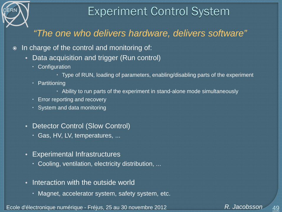
In charge of the control and monitoring of: • Data acquisition and trigger (Run control) Configuration
Type of RUN, loading of parameters, enabling/disabling parts of the experiment Partitioning
Ability to run parts of the experiment in stand-alone mode simultaneously Error reporting and recovery System and data monitoring
• Detector Control (Slow Control) Gas, HV, LV, temperatures, ...
• Experimental Infrastructures Cooling, ventilation, electricity distribution, ...
• Interaction with the outside world Magnet, accelerator system, safety system, etc.
49
“The one who delivers hardware, delivers software”

R. Jacobsson Ecole d'électronique numérique - Fréjus, 25 au 30 novembre 2012
Short configuration time!! • No bottlenecks
Decouple data path from control path Common approach in the design and implementation of all parts of the system
• Easy inter-subsystem integration Scalable & Flexible
• Allow for the integration of new detectors Integrate the different activities
• Such that rules can be defined (ex: Stop DAQ when Slow Controls is in Error) Allow Stand-alone control of sub-systems
• For independent development and concurrent usage. Automation
• Avoids human mistakes and speeds up standard procedures Easy to operate
• Two to three operators (non-experts) should be able to run the experiment. Maintainable
• Experiments run for many years
GUIs run nothing vital, pull the plug concept 50

R. Jacobsson Ecole d'électronique numérique - Fréjus, 25 au 30 novembre 2012
All the components of the system need to be configured before they can perform their function
• Detector channels: thresholds, calibration constants need to be downloaded • Processing elements: programs and parameters • Readout elements: destination and source addresses • Trigger elements: Programs, thresholds, parameters
Configuration needs to be performed in a given sequence Databases
• The data to configure the hardware and software is retrieved from a database system. No data should be hardwired in the code (addresses, names, parameters, etc.)
Data driven code • Generic software should be used wherever possible (it is the data that changes) • (Readout flow and control flow are (should be) decoupled! • Loss of communication doesn’t mean the the data taking has to be stopped, just
recover communication on the fly!
51

R. Jacobsson Ecole d'électronique numérique - Fréjus, 25 au 30 novembre 2012
Often stated: “FE ASICs are expensive!” • Resource economy on spy buffers, counters and status…. NO! • The cost of difficult and long diagnostics downtime, and recovery procedures is sizeable Multiplied by the number of components = $$$!
List of advice
• No write only registers • Automatic checking of write actions (write – read) • Counters of sufficient width to avoid wrap-around • Simultaneously sampled read buffers for status and counter registers • Status registers reflecting the states of circuits and pieces of operational logic should be
available on the ECS bus in three versions 1. Live status 2. Sampled status by snapshot to be coherent with counters 3. Latched value upon change to the abnormal state
52

R. Jacobsson Ecole d'électronique numérique - Fréjus, 25 au 30 novembre 2012 53
Aspects of implementing generic and integrated remote control of electronics devices
• Define a generic data structure which reflects the control configuration of a board and
which interfaces to Local control actions GUI display Overall expert system for automation
• Provide an interface between the functional view and the hardware view of the system
• Provide a simple and economical remote access protocol to any board resource type independent of the bus type.
• Provide a simple and economical protocol which allows monitoring counter and status information
Expert System
Control system
Device representation
Communication
Control Interface
Busses
Hardware

R. Jacobsson Ecole d'électronique numérique - Fréjus, 25 au 30 novembre 2012
Generic view of a distributed control system (ex PVSS)
54

R. Jacobsson Ecole d'électronique numérique - Fréjus, 25 au 30 novembre 2012
A device type is represented by a dynamic data base structure
• Each board is an instantiation of the structure
A full representation and storage of all resources for control and monitoring
• Version Cross-check with board/firmware version
• FPGA code File pointers
• Hardware view – registers Readings and settings to verify control operations on
hardware (writing always followed by reading) • Functional view – parameters Readings and settings to display separately in GUIs
• State Global status information used by expert system
• Actions Dynamic structures associated with the server
commands and services
55
BoardType {struct Version { }struct FPGAcode { } struct State {
int RunStatebool WriteErrorbool StatusErrorbool Monitoredbool Owner } }
struct Registers {struct Readings { }struct Settings { } }
struct Parameters {struct Readings { }struct Settings { } }
struct Action {struct ReadWriteRegisters {}struct UpdateRegisters {}struct ReadWriteTable {}struct UpdateTable {}struct SubscribeRegisters {}struct UpdateSubscribedRegisters {}struct DownloadFPGA {}struct FPGALoadStatus {} }
}

R. Jacobsson Ecole d'électronique numérique - Fréjus, 25 au 30 novembre 2012
Obviously requires some convention on the type of devices or rather the different access modes
• E.g. Q1 means FPGA on Local Bus with base address 0x1000
• E.g. I2C_40 means an I2C device with base address 0x40
Created with Device Type Editor
56
struct Registers {struct Readings {
struct Q1 { int R000int R004…}
struct Q2 { int R000int R004…}
struct I2C_40 { int R00…}
}struct Settings {
struct Q1 { int R000int R004…}
struct Q2 { int R000int R004…}
struct I2C_40 { int R00…}
}
Hardware view
R. Jacobsson Ecole d'électronique numérique - Fréjus, 25 au 30 novembre 2012
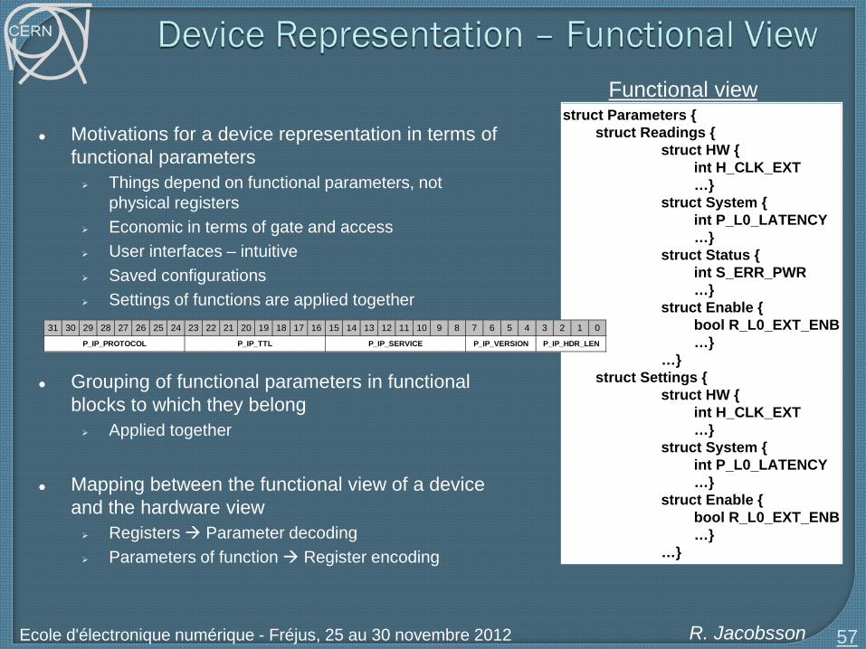
Motivations for a device representation in terms of functional parameters Things depend on functional parameters, not
physical registers Economic in terms of gate and access User interfaces – intuitive Saved configurations Settings of functions are applied together
Grouping of functional parameters in functional blocks to which they belong Applied together
Mapping between the functional view of a device
and the hardware view Registers Parameter decoding Parameters of function Register encoding
57
Functional view struct Parameters {
struct Readings {struct HW {
int H_CLK_EXT…}
struct System {int P_L0_LATENCY…}
struct Status { int S_ERR_PWR …}
struct Enable {bool R_L0_EXT_ENB…}
…}struct Settings {
struct HW { int H_CLK_EXT…}
struct System {int P_L0_LATENCY…}
struct Enable {bool R_L0_EXT_ENB…}
…}
31 30 29 28 27 26 25 24 23 22 21 20 19 18 17 16 15 14 13 12 11 10 9 8 7 6 5 4 3 2 1 0
P_IP_PROTOCOL P_IP_HDR_LENP_IP_VERSIONP_IP_SERVICEP_IP_TTL

R. Jacobsson Ecole d'électronique numérique - Fréjus, 25 au 30 novembre 2012
Instead of hard-coded Dynamic translation whenever there is a read/write operation using descriptor information
• Register Descriptor Same structure for any device type One instantiation per device type Information for Register Parameter, Functional block Registers, Data Subscription Parameter info: {Addr, Method, Type, ParamName, FuncBlock, Width, Position, Check}
Descriptor Editor Generic Translation API Manager
58
Device1 {struct Version { } struct Registers {
struct Q1 { }struct Q2 { }struct Q3 { }struct Q4 {
. . .string R01C [ ] ={ {0x4034, 1, 1, P_IP_HDR_LEN, FrontEnd, 4, 0, 1}
{0x4034, 1, 1, P_IP_VERSION, FrontEnd, 4, 4, 1} {0x4034, 1, 1, P_IP_SERVICE, FrontEnd, 8, 8, 1}
{0x4034, 1, 1, P_IP_TTL, FrontEnd, 8, 16, 1} {0x4034, 1, 1, P_IP_PROTOCOL, FrontEnd, 8, 24, 1} }
. . . } }struct FuncBlocks { }struct DataSubscribe { }
}

R. Jacobsson Ecole d'électronique numérique - Fréjus, 25 au 30 novembre 2012
59
ReadWriteRegisters
Display Readings
Parameter Readings
Register Readings
UpdateRegister Structure
Parameter Settings
ReadWriteStructure
Register Settings
Control System
TranslationParam Regs
for FuncBlock
Display Settings
TranslationRegs Params
Automaticcomparison
GUI
SERVERRead->Set->Write->Read to hardware
Service(UpdateRegisters)
Command(ReadWriteRegisters)
Control Interface
Control network
Expert system “Apply”
“Apply”

R. Jacobsson Ecole d'électronique numérique - Fréjus, 25 au 30 novembre 2012
60
LVDev1
LVDev2
LVDevN
DCS
SubDetNDCS
SubDet2DCS
SubDet1DCS
SubDet1LV
SubDet1TEMP
SubDet1GAS
…
…
Com
man
ds
DAQ
SubDetNDAQ
SubDet2DAQ
SubDet1DAQ
SubDet1FEE
SubDet1RO
FEEDev1
FEEDev2
FEEDevN
ControlUnit
DeviceUnit
…
…
Legend:
INFR. TFC LHC
ECS
HLT
Sta
tus
& A
larm
s
ex. LHCb Controls Architecture

R. Jacobsson Ecole d'électronique numérique - Fréjus, 25 au 30 novembre 2012
General purpose strategy for a large control system • Commonality • Generic control interface server • Dynamic communication protocol • Representation of resources and storage in control system • Automatic handling of parameters and registers • Interface to supervisor control system and automated expert system
• Fault detection and automatic recoveries
Operation slogan
• “Produce your own data” = Physicist non-expert shifter to operate experiment 24h
61
R. Jacobsson Ecole d'électronique numérique - Fréjus, 25 au 30 novembre 2012
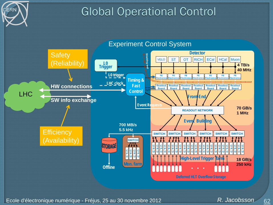
62
Experiment Control Systtem
LHC
SWITCH
High-Level Trigger farm
Detector
Timing & Fast
Control
SWITCHSWITCH SWITCH SWITCH SWITCH SWITCH
READOUT NETWORK
LHC clock
Event Requests
Event Building
Front-End
Readout Board
VELO ST OT RICH ECal HCal Muon
SWITCH
Mon. farm
Readout Board
Readout Board
Readout Board
Readout Board
Readout Board
Readout Board
FEElectronics
FEElectronics
FEElectronics
FEElectronics
FEElectronics
FEElectronics
FEElectronics
L0 trigger
L0 Trigger
700 MB/s5.5 kHz
Offline
70 GB/s1 MHz
Deferred HLT Overflow Storage
. . .
CPU
CPU
CPU
CPUC
PU
CPU
CPU
CPU
CPU
CPU
CPU
CPU
CPU
CPU
CPU
CPU
CPU
CPU
CPU
CPU
CPU
CPU
CPU
CPU
CPU
CPU
CPU
CPU
4 TB/s40 MHz
18 GB/s250 kHz
Experiment Control System
HW connections
SW info exchange
Safety (Reliability)
Efficiency (Availability)

R. Jacobsson Ecole d'électronique numérique - Fréjus, 25 au 30 novembre 2012
Specifications, and Non-conformities, non-conformities, non-conformities
Consequences of common denominator Detector is as good as its smallest constituents Less performance (TOF, RICH)
System validation in final environment Validation and review process Testing phases
• Unit testing => one or a few classes/procedures • Integration testing => different components together • System testing => overall functionality through all layers
By the way, pipelined logic is strongly preferred, limited use of combinational logic
• More tolerant to code changes and environmental changes, faster re-validation process
63

R. Jacobsson Ecole d'électronique numérique - Fréjus, 25 au 30 novembre 2012
64

R. Jacobsson Ecole d'électronique numérique - Fréjus, 25 au 30 novembre 2012
Levels of simulation • Behavioural/functional simulation - emulation • Clock level simulation – synthesizable code = development framework • Timing simulation – after placing&routing = resource usage Slice simulation
65
Emulation
Clock level
Timing
Synthesis & Place&Route
Readout Control (Stimuli)
FE(Processing) ROB(Response)
SynthesisableVHDL
Readout Control (Stimuli)
FE(Processing) ROB(Response)
Readout Control (Stimuli)
FE(Processing) ROB(Response)
Readout Control (Stimuli)
FE(Processing) ROB(Response)
Stage 1:
Stage 2:
Stage 3:
Stage X:
Ex. FE development:

R. Jacobsson Ecole d'électronique numérique - Fréjus, 25 au 30 novembre 2012
Well choses system level simulation tool • Personal favourite: VisualElite from Mentor Graphics • Make sure models are portable!
Example shows another fact: Readout control must be well specified and developed ahead of the rest Thus, contain flexibility and important reserve resources to accommodate changes
Control and monitoring resources should be simulated ! Emulation of the actual control interface (µController, NIOS, PC….) Direct extraction and generation of system configuration from real system at single click Allows snap-shooting and reproducing the Situation
Simulation framework maintained through life of the experiment • Mode of operation is bound to evolve in High Energy Physics
66
Readout Control (Stimuli)
FE(Processing) ROB(Response)
CTRL Interface
Control data extraction& conversion

R. Jacobsson Ecole d'électronique numérique - Fréjus, 25 au 30 novembre 2012
FE model can be exchanged to check compatibility with common specs
67

R. Jacobsson Ecole d'électronique numérique - Fréjus, 25 au 30 novembre 2012
Grounding Shielding Heat dissipation
68

R. Jacobsson Ecole d'électronique numérique - Fréjus, 25 au 30 novembre 2012
Failure rate > probability of failure * number of pieces
(LHC accelerator 250 kCHF / hour !)
Availability, reliability, fault tolerance, error behaviour • Handling errors, not stop data taking! • Low probability of failure multiplied by enormous number of systems • Parallel continued validation, problem isolation
Are the board on the shelf functional? • Swapping concept against plugging fatigue
Infant mortality • Stress screening • Run in • Burn in
Ageing • Maintenance • Upgrade
Failu
re ra
te
Time
Expert availability…
R. Jacobsson Ecole d'électronique numérique - Fréjus, 25 au 30 novembre 2012
70
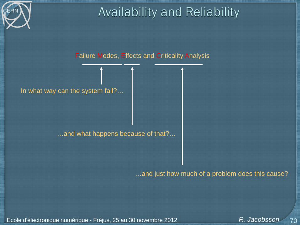
Failure Modes, Effects and Criticality Analysis
In what way can the system fail?…
…and what happens because of that?…
…and just how much of a problem does this cause?
R. Jacobsson Ecole d'électronique numérique - Fréjus, 25 au 30 novembre 2012
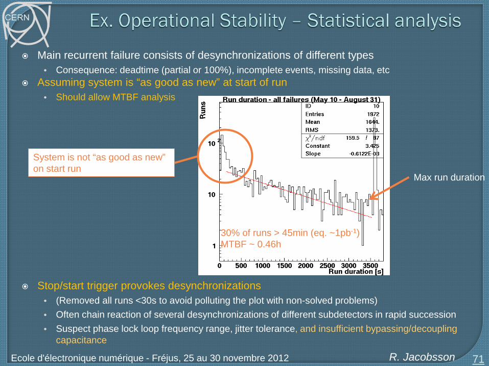
Main recurrent failure consists of desynchronizations of different types • Consequence: deadtime (partial or 100%), incomplete events, missing data, etc
Assuming system is “as good as new” at start of run • Should allow MTBF analysis
Stop/start trigger provokes desynchronizations
• (Removed all runs <30s to avoid polluting the plot with non-solved problems) • Often chain reaction of several desynchronizations of different subdetectors in rapid succession • Suspect phase lock loop frequency range, jitter tolerance, and insufficient bypassing/decoupling
capacitance 71
30% of runs > 45min (eq. ~1pb-1) MTBF ~ 0.46h
Max run duration
System is not “as good as new” on start run

R. Jacobsson Ecole d'électronique numérique - Fréjus, 25 au 30 novembre 2012
Why do we need to upgrade?
• “It works - don’t touch anything!”
Upgrades are needed because of: • Request for improvements and new functionality • Changes in other parts of the system, both HW and SW • Expiration of support contracts • Obsolescence of components • Ageing • (Keep experts hooked and motivated….)
Holding back upgrades for too long is not sane
• Batching many changes makes troubleshooting much more difficult • People forget how their code works • Modern engineering advocates one small change at a time (a.k.a. “continuous delivery”)
72

R. Jacobsson Ecole d'électronique numérique - Fréjus, 25 au 30 novembre 2012
Trigger, data acquisition and control systems are becoming increasingly complex
They are not static • It is a system that is expected to change with time, accelerator and experiment conditions • Provide maximum flexibility in functionality and for upgrades
Luckily the requirements of telecommunications and computing in general have strongly
contributed to the development of standard technologies: • Hardware: FPGAs, Flash ADCs, analog memories, PCs, networks, helical scan recording, data
compression, image processing, ... • Software: distributed computing, software development environments, supervisory systems, ...
We can now build a large fraction of our systems using commercial components
(customization is still needed in the front-end)
It is essential that we keep up-to-date with the progress being made by industry
But it is also essential that we go beyond industry! • Basic research is what we need to build a long-term potential for technical progress
73

R. Jacobsson Ecole d'électronique numérique - Fréjus, 25 au 30 novembre 2012 74
•Passive Optical Network •Point-to-MultiPoint (PMP) optical network
•One single fibre in charge of both downstream and upstream transmissions •Basis of all the growing Access Network market (also called FTTH/B/C/x)
1490 nm
1310 nm