Earthquake Loadings and Steel Structures€¦ · · 2015-08-13Section 13 of Australian Standard...
40
Earthquake Loadings and Steel Structures L. Pham CSIRO Division of Building Construction and Engineering, Australia 1. INTRODUCTION This paper reviews the effects of earthquake loadings on various types of steel structures such as towers and masts, buildings, bulk solids containers and liquid storage tanks. With the publication of AS 1170.4--1993 Earthquake Loads, the design provisions for some of these structures in various Australian Standards have to be revised since they were originally written to be compatible with the old Australian Standard for earthquake AS 2121- 1979. Background to the draft revisions to Australian Standards for the design of steel lattice towers AS 3995-1991, for the design of steel structures AS 4100-1990 and for loads on bulk solids containers AS3774-1990 with regard to earthquake effects are presented. Problems associated with the design of liquid storage tanks for earthquake effects are also discussed. 2. STEEL LATTICE TOWERS AND MASTS Current AS 3995(1nt)-1991 has made no reference to earthquake effects on lattice towers and masts. This type of structure is less sensitive to earthquake loads than most other types. Consequently, only an informative appendix has been proposed for the revision to cope with the problem. For lattice towers less than 100m high and with no significant mass concentration, it is generally not necessary to consider earthquake effects. A significant mass concentration has been defined as a concentration of mass greater than 25% of the total mass of the structure. For other cases, it might be advisable to check the base shears and overturning moments; although it is expected that wind loading consideration will probably control the design. For towers and masts in Earthquake Design Category D and E, vertical earthquake motions may be a significant factor and need to be considered in design. This is particularly true for very tall masts, for which the differential vertical movements between the mast base and guy anchorage points may lead to drastic force redistribution and the possibility of buckling of the mast. Footing ties are also advisable when the footings are founded on soft soils or topographic extremes. 3. STEEL BUILDINGS General Section 13 of Australian Standard for Steel Buildings AS 4100--1990 was written to be compatible with the requirements of AS 2121-1979 the SAA Earthquake Code. This section has been completely redrafted to conform with AS 1170.4-1993. The new draft Section 13 defines two levels of design requirements for steel structures. The first level, which is applicable to all structures in Earthquake Design Category A, B 35
Transcript of Earthquake Loadings and Steel Structures€¦ · · 2015-08-13Section 13 of Australian Standard...
Earthquake Loadings and Steel Structures
L. Pham CSIRO Division of Building Construction and Engineering, Australia
1. INTRODUCTION
This paper reviews the effects of earthquake loadings on various types of steel structures such as towers and masts, buildings, bulk solids containers and liquid storage tanks.
With the publication of AS 1170.4--1993 Earthquake Loads, the design provisions for some of these structures in various Australian Standards have to be revised since they were originally written to be compatible with the old Australian Standard for earthquake AS 2121- 1979. Background to the draft revisions to Australian Standards for the design of steel lattice towers AS 3995-1991, for the design of steel structures AS 4100-1990 and for loads on bulk solids containers AS3774-1990 with regard to earthquake effects are presented. Problems associated with the design of liquid storage tanks for earthquake effects are also discussed.
2. STEEL LATTICE TOWERS AND MASTS
Current AS 3995(1nt)-1991 has made no reference to earthquake effects on lattice towers and masts. This type of structure is less sensitive to earthquake loads than most other types. Consequently, only an informative appendix has been proposed for the revision to cope with the problem.
For lattice towers less than 100m high and with no significant mass concentration, it is generally not necessary to consider earthquake effects. A significant mass concentration has been defined as a concentration of mass greater than 25% of the total mass of the structure. For other cases, it might be advisable to check the base shears and overturning moments; although it is expected that wind loading consideration will probably control the design.
For towers and masts in Earthquake Design Category D and E, vertical earthquake motions may be a significant factor and need to be considered in design. This is particularly true for very tall masts, for which the differential vertical movements between the mast base and guy anchorage points may lead to drastic force redistribution and the possibility of buckling of the mast.
Footing ties are also advisable when the footings are founded on soft soils or topographic extremes.
3. STEEL BUILDINGS
General
Section 13 of Australian Standard for Steel Buildings AS 4100--1990 was written to be compatible with the requirements of AS 2121-1979 the SAA Earthquake Code. This section has been completely redrafted to conform with AS 1170.4-1993.
The new draft Section 13 defines two levels of design requirements for steel structures. The first level, which is applicable to all structures in Earthquake Design Category A, B
35

and regular structures of Category C, imposes no extra requirements for earthquake design. By implication, if a moment resisting frame is used it will have to be an ordinary moment resisting frame. The second level, which is applicable to all structures in Earthquake Design Category D, E and irregular structures of Category C, imposes some extra requirements for earthquake design to ensure adequate ductility. It is argued that for Australian condition a finer classification is not warranted.
Extra requirements for Category D, E and C (irregular).
The extra requirements for steel structures of Earthquake Design Category D, E and C (irregular) are aimed at improving the ductillity of the structures. These include:
1. Limiting the design axial force for diagonal tension brace to 0.85 times the design tension capacity
ii. Full depth, butt welded web stiffeners.
iii. Bracing members for over two storey buildings to have compressive strength of at least 50% the required tensile strength
IV. All welds to be of SP Category
No recommendations are given for eccentrically braced frames at this stage because the unliklihood of their applications in Australia. For moment resisting frames, designers have the choice of ordinary, intermediate or special moment resisting frames.
For ordinary moment resisting frames, no additional requirements are specified, but the designers have to use a relatively low Rr (= 4.5), i.e. a higher design earthquake force. For intermediate moment resisting frames, the requirements are the same as that for plastic design of AS 4100, but the design earthquake force is lower with Rr = 6.5. For special moment resisting frames which are not expected to be used much in Australia, a higher Rr = (8.0) is allowed but with more additional requirements on compression members (to rely on their own bending stiffness for lateral stability) and connections (to develop full plastic moment capacities of the connecting beams).
4. STEEL BULK SOLID CONTAINERS
General
Earthquake loads on bulk solids containers are specified in Clause 7.4 of AS 3774-1990. This clause was written to conform with the requirements of AS 2121-1979 and will have to be revised to match the requirements of AS 1170.4-1993. The proposed revisions do not change the basic approach to the problem as formulated by Irvine in AISC Structural Design of Steel Bins for Bulk Solids.
Ground supported structures.
For ground supported structures, the earthquake induced pressures on the wall of the containers are dependent on the ratio of length L (or diameter D) to height H of the container. For a container with a bulk solid density g, situated at a location with acceleration coefficient a, site factor S and importance factor I (a, I and S as defined in AS 1170.4-1993), the followings have been proposed.
36

For rectangular container, the nonnal wall pressure Pnw may be treated as uniformly distributed and can be written as
Pnw = 0.5 L (g a I S) Pnw = H (g a IS)
forL/H < 2 forL/H > 2
and side wall horizontal frictional traction pq
Pq = 0.5 L (g a I S) Pq= H(gaiS)
forL/H<2 forL/H <2
For circular container, the pressures may be taken as constant up the height of the container and vary around the circumference. The nonnal wall pressure can be written as:
Pnw = 0.25 D (g a I S) cosq Pnw = 0.50 H (g a IS) cosq
forD/H < 2 forD/H> 2
and circumferential frictional traction
Pq = 0.25 D (g a I S) sinq Pq = 0.50 H (g a I S) sinq
forD/H < 2 forD/H > 2
Elevated containers and supporting structures
For elevated containers, the earthquake loads should be estimated in accordance with AS 1170.4, i.e.
H = I (C SIRe) W
where
1. H = the earthquake induced horizontal load ii. W = the gravitational force on the total mass of the container and its contents.
Other tenns in the equation are similar but different from the current AS 3774-1990 specification.
iii. I = importance factor = 1.25 for installation of critical importance (currently AS3774
specifies 1.5) = 0.8 for containers on farms and isolated locations = 1.0 for all other
iv. Rc = structural response factor = 2. 8 for braced and unbraced legs ( currently distinction is made of
braced, unbraced moment resisting non-ductile and ductile frame supports in AS3774 with different factors for structural response)
v. c = earthquake design coefficient = 1.25 a I J'2/3
with
a = acceleration coefficient which shall be found from AS 1170.4
37

and
T = the structure period
= 2 p...j(W/K)
In AS 3774, a slightly different design earthquake spectrum was assumed, resulting in the value of C being proportional to T-1/l instead of T--2!3 .
(f) s = site factor which shall be taken as given in AS 1170.4
Steel Liquid Storage Tanks
There is no Australian Standard for the structural design of steel liquid storage tanks at present. Guidance can be obtained from American Standard API 650 which is based on the work of Wozniak. Design rule has also been proposed by Priestly in the New Zealand (Recommendations for seismic design of storage tanks). Another available guideline is by the American Society of Civil Engineers.
Problems associated with the design of tanks for earthquake induced forces include:
1.
11.
iii.
pressure due to sloshing of the liquid pressure due to the horizontal tank motion pressure due to the interaction vibration of the tank shell and the liquid.
Distinction should also be made of anchored and unanchored tanks. For the latter, the uplift of the tank bottom edge is a possibility that should be considered.
Stability and load carrying capacity of the tank wall can be analysed by finite element methods.
38

Masonry Structures - Earthquake Resis.tant Design and Construction
J.C. Scrivener Department of Building, University of Melbourne, Australia
1. INTRODUCTION
Masonry has a bad performance record in earthquakes around the world. One becomes very used to the press, both written and electronic, telling us that 'the masonry buildings collapsed like packs of cards' and 'there was massive loss of life in the masonry housing'. The newspapers love these and other dramatic phrases - perhaps it is, after all, news!
But what the press does not tell the reader or listener is that the masonry structures they reported so dramatically, were usually:
• not designed to any engineering code, let alone an earthquake code • poorly constructed of adobe, mud brick or weak clay bricks with weak mortar of
mud or earth or too little cement. • of unconnected structural elements often with heavy roofs.
This paper attempts to show, in its first part, that unreinforced masonry properly designed and constructed can resist moderate earthquakes. With the introduction of reinforcement, dealt with in the second part, masonry can be made ductile enough to withstand major earthquakes.
Frequent reference will be made to the relevant sections of two codes AS 1170.4, Minimum Design Loads on Structures, Part 4, Earthquake Loads (Standards Australia 1993) and AS 3700 SAA Masonry Code (Standards Australia 1988).
2. UNREINFORCED MASONRY
The materials of unreinforced masonry include clay brick, concrete brick and block, stone, adobe and mud brick.
In a recent study of the performance of old masonry in earthquakes Scrivener (1992 a and b) found that the major causes of earthquake damage were:
• poor quality of materials and construction • inadequate connections between structural elements • unsatisfactory structural layout • effects of soil-structure interaction
Before discussing these points, the design and detailing requirements of AS 1170.4 (Standards Australia 1993) will be considered. Unreinforced masonry is a brittle material expressed in the code as 'non-ductile'. The design and detailing requirements for 'general' structures are given in Clause 2.7 and for 'domestic' structures in Section 3. These requirements have been re-expressed for unreinforced masonry in Table 1 for 'general' structures and in Table 2 for 'domestic' structures.
39

Design Category
A
B
c
D
E
TABLE 1. Design and Detailing Requirements for Unrein forced Masonry General Structures
General Product of Structural Analysis for Restrictions on Structure Earthquake Detailing Earthquake Load Bearing
Type Acceleration Requirement Forces Masonry (Note 1) and Site Clause Components
Factor (aS) (Note 2)
I aS<O.l 4.3 None None
II aS<O.l 4.3 Static-Sect. 6 1-3 storeys
I O.l~aS<0.2 or 4 or more storeys-
Dynamic-Sect. 7 some unreinforced
walls with
reinforced walls
III aS<O.l 4.4 As forB As forB
II 0.1~aS<0.2
I aS~.2
III 0.1 ~aS<0.2 As forB 1-2 storeys
II aS~.2 4.4 3 or more storeys -
some unreinforced
walls with
reinforced walls
not permitted - -
NOTES TO TABLE 1:
1. General Structural Type:
III Buildings essential to post-earthquake recovery or associated with hazardous facilities
II Buildings designed for a large number of people or people of restricted mobility I Buildings not of types I or II
2. The Structural Detailing Requirements of Clause 4.3 include:
the requirements of AS 3700 beam and truss connections to supports to have a minimum strength of 5% of reaction due to gravity load anchorage of walls tc roof and floors to resist lO(aS) kN per metre run of wall. For Design Category A, a 50% reduction is permitted but the minimum force shall not be less than 0.8 kN per metric run of wall
Clause 4.4 specifies in addition to the requirements of Clause 4.3, certain further requirements in relation to connections, diaphragms, openings and footings.
40

TABLE 2. Design and Detailing Requirements for Unrein forced Masonry Domestic Structures
Design Category Product of Structural Detailing Analysis for Earthquake Requirement Earthquake Forces
Acceleration and Clause (Note 1) Site Factor (aS)
H1 aS<0.1 None None
H2 0.1~aS<0.2 3.3 None
H3 aS~.2 3.3 Static analysis-clause
3.4 (Note 2)
NOTES TO TABLE 2:
1. The Structural Detailing Requirements of Clause 3.3 include:
all parts of structure to be tied together beam and truss connections to supports to have a minimum strength of 5% (7.5%) of reaction due to gravity load for Design Category H2(H3) anchorage of walls to roof and floors to resist 10 (aS) kN per metre run of wall.
2. Clause 3.4 on static analysis requires design for a horizontal base shear force of 15% of gravity load and other provisions.
The major causes of earthquake damage will now be considered in turn.
2.1 Quality of materials and construction
Procedures to ensure high quality of units, mortar and construction can be found in the Masonry Code (Standards Australia 1988) and will not be discussed further here.
2.2 Connections between structural elements
Where roofs (or floors) and walls are not well connected, horizontal movement during the earthquake causes, in the first instance, the roof (or floor) to collapse leaving the walls without lateral support which can precipitate their collapse. Clauses 3.3.2 and 4.3.3 of AS 1170.4 require a connection 'capable of resisting a force of 10 (aS)kN per metre run of wall'. (a is the earthquake acceleration factor and S is the site factor.)
Inadequate connections between walls, again leaving walls without lateral support, are covered in AS 1170.4 by clause 3.3.2 for domestic structures and in clause 4.4 for general structures of design categories C, D and E, but no specific reference is given for design categories A and B.
41

Good connections between masonry wythes or between masonry and another material (eg in a timber stud frame with masonry veneer) are also important. Page (1992), reporting on the Newcastle earthquake, gives examples of the inadequacy of ties due to corrosion or insufficient numbers at the time of construction. AS 1170.4 does not give specific reference to ties but the matter is covered in Section 3 of the Masonry Code.
2.3 Structurallayout
Five major causes were identified:
• lack of cross walls • weaknesses created by doors and windows • inadequate diaphragm action • massiveness of construction • asymmetric plan shape.
This paper will not attempt to comment on the first three of these causes and their remedies will be obvious to structural engineers. In regard to the 'massiveness of construction', it is of interest to note that in the television report of the recent Indian earthquake, housing with the traditional straw roofs smvived while the more affluent housing with 'new' concrete roofs collapsed. The increased horizontal base force due to the mass of the heavy roof was the culprit here.
The Newcastle eanhquake had a classic example of the torsional effect of asymmetric plan shape on the performance of a building. The ground floor of a block of apartments had many walls at the back, where the laundries and toilets were located, and few walls at the front, where the residents' cars were parked. The damage at the back was extensive- one could put one's fist into the crackswhile the front was relatively undamaged.
The earthquake loading code deals with each of these structural layout matters.
2.4 Soil structure interaction
Masonry structures, particularly those of low height, have high fundamental frequencies. For most earthquakes and sites, greater inertial forces have to be carried by masonry buildings than by other buildings of lower fundamental frequency.
However, local site characteristics may alter this situation eg. in Mexico City and in Central Greece.
3. REINFORCED MASONRY
There is now ample evidence that reinforced masonry can behave in a ductile manner. Tests in the 1960's and 1970's clearly showed this; for example, in New Zealand by Scrivener (1969), Scrivener and Williams (1971) and Priestley and Bridgeman (1974) ~ in Mexico by Meli (1972); and in the USA by Mayes and Clough (1975). The earthquake code reflects this ductile behaviour in Table 6.2.6 (a) by rating reinforced masonry bearing walls and building frame systems just slightly below reinforced concrete in ductility of structural response and deflection amplification.
Reinforced masonry has many similarities with reinforced concrete such that designers, and codes, have borrowed from reinforced concrete research and knowledge leading to reinforced masonry design methods and rules much like those of reinforced concrete.
42

But there are a number of significant differences between reinforced masonry and reinforced concrete and the designer must be aware of these and take appropriate action The differences are:
(i) Because of the geometric limitations posed by hollow masonry, and also by double skinned (plain) masonry with a reinforced grouted cavity between the skins, it is difficult to confine compressive reinforcement.
In a reinforced concrete compression member, the longitudinal reinforcement is restrained from bursting out laterally by the ligatures. In the hollow core of reinforced masonry and/or in the narrow width of the grouted cavity there is simply insufficient room for a ligature. Some argue that the ligatures could be placed in the bedjoints of the masonry but this is unsatisfactory for several reasons. Reinforcement in bed joints must necessarily be of small diameter; it has little protection from the elements as the bed joints are prone to cracking and the very presence of bed joint reinforcement is considered to enhance the possibility of cracking in the joint. Further, if and when the material, mainly masonry, outside the longitudinal reinforcement spalls due to high compressive forces the ligature in the masonry becomes completely ineffective.
In some instances, eg piers, it can be arranged for masonry units to surround a reasonably sized inner portion of concrete or grout with longitudinal reinforcement and ligatures.
But, generally, the compression capacity of masonry is the 'unconfined' capacity which is somewhat lower than the 'confined' capacity of reinforced concrete members.
(ii) In the flexural situation (eg with lintel beams) again ligatures are most difficult to provide and the potential capacity of the beam may not be reached due to the lack of sufficient shear resistance.
(iii) Reinforced masonry is constructed with built-in weaknesses at the horizontal and vertical bed joints. With cementitious joints, the bond between the masonry units and the mortar can become the cruc·ial factor - and it is extremely difficult to increase cementitious bond greatly.
(iv) Reinforced masonry can only act in a similar way to reinforced concrete provided that the grout, or concrete, filling around the reinforcement is adequately bonded to the masonry units. In most circumstances, this bond is easy to provide. But the effect of the grout in adding to the compressive capacity of the masonry is less than would be expected - see clause 6.3.1 of the masonry Code - probably due to the different strain rates of the two materials causing some separation between them.
(v) Perhaps the most important difference results from the construction.
It is comparatively simple to place concrete satisfactorily within formwork and because we have been doing this for some time all those involved in the construction are aware of the best techniques. Placement of grout within reinforced masonry is less simple as the grout has to flow in a confined space between absorbent surfaces. It is difficult to see whether the grout has fully covered the reinforcement which is essential for full strength, and consolidation of the grout may not be easy unless the grout, in position, is very workable. And the construction community, particularly in Australia, has had little experience of reinforced masonry construction. But with care, and frequent inspection and control from designer and contractor, completely satisfactory grout and reinforced masonry is possible.
43

The techniques for grouting are well documented (Standards Association of New Zealand 1981).
4. NON STRUCTURAL COMPONENTS
In areas prone to severe earthquakes (eg. Japan, West Coast USA, and New Zealand) it has been found that one of the greatest earthquake hazards is the falling of ornaments and parapets from buildings on to footpaths and roadways. While just outside a building is the least safe place to be in an earthquake, it is instinctive for those within a building to run outside at the onset of the earthquake and so be in danger of falling objects. Graphic illustrations can be found in the Newcastle earthquake report (Page 1992), and in the Meckering earthqoake (Cox). -
The earthquake code devotes the entire section 5 to this matter and defines earthquake coefficients for design which are at least as high as those for structural elements.
5. CONCLUSION
Masonry if carefully
• designed • detailed, and • constructed
to the earthquake load and masonry codes, can withstand moderate earthquakes and, if reinforced, major earthquakes.
6. REFERENCES
Mayes R .L. and Clough R.W. (1975). Cyclic shear tests on fixed-ended masonry piers. American Society of Civil Engineers, National Structural Engineering Convention, New Orleans, April
Meli R. (1972). Behaviour of masonry walls under lateral loads. Proc .. 5th World Conference on Earthquake Engineering, Rome.
Priestley M.J.N. and Bridgeman D.O. (1974). Seismic resistance of brick masonry walls. Bulletin New Zealand Society for Earthquake Engineering, Vol. 7, No.4.
Scrivener J.C. (1992a ). The performance of old masonry in earthquakes, Structural Masonry for Developin~ Countries, Proc .. 4th Int. Sem., Dec. 1992, Madras, pp 262-7.
Scrivener J.C. (1992b). Old masonry buildings- earthquake perfonnance and material testing, Internal Report 624, Institute for Research in Construction. National Research Council of Canada, Mar. 1992.
Scrivener J C and Williams D (1971). Behaviour of reinforced masonry shear walls under cyclic loading. Bulletin New Zealand Society for Earthquake Engineering, Vol 4,No2.
Scrivener J.C. (1969). Face load tests on reinforced hollow-brick non-load-bearing walls. New Zealand Engineering, July, pp 215-220.
Standards Australia (1993)- AS 1170.4, Minimum design loads on structures, part 4, earthquake loads, p 64.
Standards Australia (1988 )- AS 3700, SAA Masonry Code, p 48.
Standards Association of New Zealand (1981 ). Code of practice for masonry buildings: materials and workmanship. Provisional New Zealand Standard NZ54210P.
44

Mechanical and Electrical Equipment
J.L. Wilson and N.T.K. Lam Department of Civil & Environmental Engineering, University of Melbourne, Parkville, Australia
1. INTRODUCTION
Past earthquakes around the world have demonstrated the need for the aseismic design of mechanical and electrical equipment to mitigate propeny losses and protect life during a severe earthquake event. Equipment located in the buildings is subjected to modified and often amplified earthquake motions (Fig. 1). In particular equipment that has been isolated to minimise the transmission of vibrations to the building and its occupants under nonnal operation can experience significant amplifications if the natural frequencies of the isolated equipment and building are closely spaced and resonance develops.
Figure 1 - Transmission of ground vibrations within a building
Section 5 of the new Australian Earthquake Loading Standard, AS 1170.4 (Ref 1) provides guidance for the design of mechanical and electrical equipment to resist earthquake loading.
These provisions are critically reviewed in this paper and compared with the results from an analytical study carried out using a two degree of freedom model subjected to earthquake ground motions.
An alternative design method to Section 5 of AS 1170.4 for calculating earthquake forces on equipment is presented based on the results from the analytical investigation.
2. AS1170.4 SECTION 5
AS 1170.4 provides the following equation for the calculation of eanhquake forces in mechanical and electrical equipment:
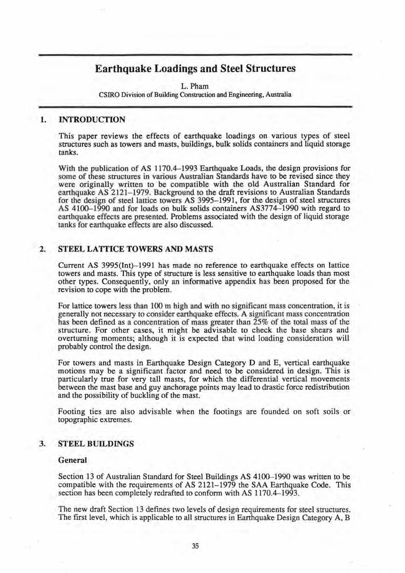
Fp = al SAx Ac Cc W (1)
45
where : a I s Ax Ac Cc
= = =
=
acceleration co-efficient importance factor soil factor height amplification factor (1.0 - 2.0) attachment amplification factor (1.0- 2.0) component earthquake co-efficient (0.6 - 2.0)
The physical interpretation of this equation is shown in Fig. 2. The product (aiS) can be considered the earthquake acceleration at ground level which is transmitted up the structure and modified by the factor Ax at higher levels. The product aiSAx can be considered the floor acceleration which excites the equipment expressed as a proportion of gravity at the level under consideration.
The response of the equipment is modified from the floor response by the factor, Ac, to account for resonance effects between the building and the equipment, and the factor, Cc, to account for the ductility and importance of the equipment.
The product (al SAx Ac Cc) is the effective acceleration of the equipment expressed as a proportion of gravity.
----- Xe=(a lax) (acCc) 1-----J,----i----- Xi=aSiax
ax dc~nds on I he
level or the componcnl
Figure 2 - Effective acceleration levels, Section 5, AS1170.4
The expression for Fp has been formulated so that design professionals responsible for the functional design of such items can use this section of AS 1170.4 independently of both the structural framing system and the dynamic characteristics of the building. The appropriateness of the method is investigated using an analytical model described in the following section.
3. ANALYTICAL STUDY
A two degree of freedom model was used to simulate the response of spring mounted equipment to earthquake ground motions (Fig. 3) . The fi rst degree of freedmr. represented the dynamic characteristics of the firs t mode hape of the building whilst the second lumped mass dashpot and spring system modelled the spring mounted equipment. This model could be reduced to a single degree of freedom if the equipment was rigidly attached to the building floor.
46

~?-=\ alrg. T r &jJ-'-lTii . , II _ Xo - x.
Xg
simui:Jtes ground mol ion
simulaleS noo..-response
simulateS equipment response
Figure 3- Analytical two DOF model
A spring with a nonlinear capability was introduced to model the stiffness of the building. Two cases were considered, one where the building remained elastic under the extreme earthquake event (R = 1) and the other where the building responded inelastically with a structural response factor, R, equal to 4. Three different building heights were considered reflecting a 5, 10 and 20 storey regular building. The damping assumed in the building was 5%.
A wide range of equipment mounting systems were modelled with natural periods ranging from 0.1 seconds to 2.0 seconds and with a critical damping ratio of 0.5%.
The well documented El Centro earthquake of 1940 (Ref. 2) and two synthetic earthquakes with different durations but compatible with the S = 1 response spectrum presented in AS 1170.4 were used in the analyses. (Fig. 4 ).
47

El CENTRO Ground Molton
Recorded a1 Ei C~n1 ro
,n Cahlornta cunng
1 , Earthquake on ~ \l 1t1e lmpenal Valley
~t-~~~()Yf~ll ~ f'~ 16 MAY 19<0
.~~--~~~~~~ 0 10 1 S 20 25 JO
Ttme (sees)
Aniltctally Generated "Sisler' Ground Motion
I( sees\
Arlilictally Generated 12 s12cs Duration Hybrid Ground Motion
tnl e n'lltY Etli'IO IIII IOP~
l 0 10 I 5 20 25 JO t t:.ecs)
Figure 4 - Earthquake ground motions
The nonlinear computer program, DRAIN 2D, (Ref. 4) was used to perform the analyses.
The earthquake ground motions were scaled such that the effective peak ground acceleration was O.lOg. The scaled ground motions were then multiplied by the participation factor of the respective buildings so that the earthquake accelerations calculated would be representative of the motion at the top of the building.
The maximum accelerations of the equipment located at the top of the building under earthquake excitation were then calculated for the 5, 10 and 20 storey buildings behaving elastically (R = 1) and inelastically (R = 4). The results are plotted in Fig. 5 (reproduced from Ref. 5) for the El Centro ground motion. The equivalent equipment acceleration levels calculated using Section 5.3 of AS 1170.4, with Ax = 2 and Cc = 2 have also been presented in Fig. 5 for comparative purposes.
48

.
,, .----~...,---..,....---~---. . ...... ~ .. · ·• ""l"''~~~'"' '" "'l ~elllon•d 11 lap 14-w•l ol 1
JO EICA<luo
N.J!L:ral PeriOdol V.otatoontsec)
FloGr Sp•c111 al •qulp..,lnl
po1U1onwd 11 Lop '''"'' ol 1 ~
a, .. M•'1l tuou.-. o ~:,,:';'~'a b~;~d~~:· of "'''"'' . ~;;:~'"'" M .. u ..:.-y an- 11 ~IO':l'O
B"oldit>Qboolo"•"'"' : ~•• _. , ,"'ii'Jt.t~~j CJ< • ·n · ~
• loo• : ~taG ~
j 10~=?---"f. vn .. Ec:u0t"1•nl
L___ : -DS.,_
05 10 15 zo
~boo~ ... . , flO<:Jr Sp.ec1r1 or •qulpm•nL
.~.u ..__l t r l • •- ' 1 •• • llliofll• lll •• lvp I• • • • o • t 10 1\0fl'( bulldln!iJ, "' n1!Ur11 ,: EIC-•ru
• • •••• • l••·~•,..• • - Gltwt>dt.Aale>n 8¥~beot.)n • • ~IOOIQ ltlnln ~Uiol'lf'r (A_.l •
¥t-l1~ m«::ru~ ~
I : Rl!o:lal L-: Eq....:omanl ....
JO
Figure 5 - Floor spectra for equipment located at the top level of building (after Ref. 5)
The analytical study clearly demonstrates that the earthquake response of the equipment is very dependent on both the dynamic characteristics and the extent of inelastic behaviour of the building.
The equipment design accelerations calculated using AS 1170.4 were generally conservative provided that the equipment and building material frequencies were not closely spaced. For rigidly mounted equipment the study demonstrated that the code approach was quite conservative.
Further, the analytical study demonstrated that the equipment design accelerations significantly reduced as both the building height and inelastic demand increased. In contrast, the accelerations calculated using Section 5 of AS 1170.4 remained effectively constant. (It should be noted that this study considered only the first mode response of the building. Preliminary studies have shown that the higher modes will increase the equipment response in the order of 20% for the 10 storey and 35% for the 20 storey buildings.)
The AS 1170.4 approach was unconservative for the situation where the building and equipment natural frequencies were nearly equal, resulting in some resonance. In such situations the equipment accelerations could be significantly greater than the code predictions for short buildings, particularly if the building response remained in the elastic range.
The following section discusses an alternative and what is considered a more rational procedure for calculating the earthquake forces developed in equipment by including the effects of the building response.
49
4. ALTERNATIVE DESIGN METHOD
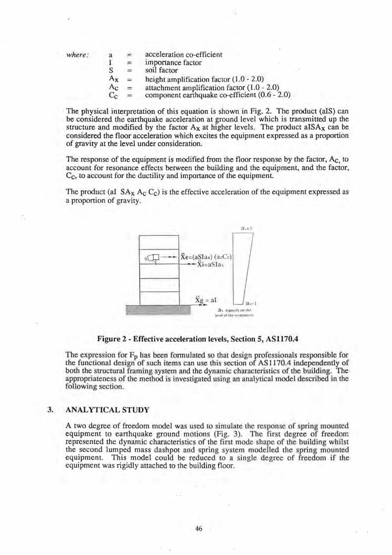
An alternative design method to Section 5 of AS 1170.4 involves the calculation of the earthquake acceleration of the floor under consideration (using either Section 6 or 7 of AS 1170.4) and then to apply a dynamic amplification factor to account for the interaction between the building and equipment.
The design earthquake floor acceleration can be considered equal to the design storey induced earthquake force divided by the storey mass (these storey forces can be calculated using the static method of Section 6, AS 1170.4 or the response spectrum method of Section 7, AS 1170.4 ). The resulting floor acceleration directly accounts for the dynamic characteristics and inelastic behaviour of the building. It is recommended that the storey acceleration at any level be interpolated from the design storey acceleration at the top of the building and the acceleration at ground level given by ai (Fig. 6).
Fn
Earthquake Force Distribution
Floor Mas s Mn Xn = Fn 1 i\·ln ~--~,--- r--~
Total Acceleration Distribut i on
Figure 6 - Effective acceleration levels, Section 6, AS1170.4
A modification needs to be made to the top storey acceleration for buildings in which the actions caused by wind loads are greater than those caused by the earthquake loads. In such cases, the building has some overstrength capacity and the top storey acceleration should be scaled by the ratio of the wind to earthquake overall building base bending moment at the ultimate limit state. This modified top storey acceleration need not exceed the acceleration value corresponding to elastic behaviour (R = 1).
The dynamic amplification factor for equipment mounted at elevation in buildings is dependent on the ratio of equipment to building frequency. Fig. 7 shows a suggested amplification factor based on an ensemble of floor motions representing a variety of earthquake ground motions, building heights and degrees of inelastic building behaviour. The shape of the curve is similar to the response of a single degree of freedom model subjected to pure harmonic excitation.
50
0
~ <:: .~ n; u
"-~ 3l <:: ~ ;;; ~ --~~--~_,~T---------~---4-
u = Equipmelll frequency/building lreouency
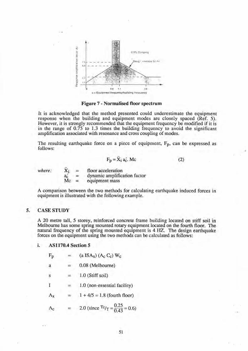
Figure 7 - Normalised floor spectrum
It is acknowledged that the method presented could underestimate the equipment response when the building and equipment modes are closely spaced (Ref. 5). However, it is strongly recommended that the equipment frequency be modified if it is in the range of 0.75 to 1.3 times the building frequency to avoid the significant amplification associated with resonance and cross coupling of modes.
The resulting earthquake force on a piece of equipment, Fp, can be expressed as follows:
.. where: Xi
aC = Me =
floor acceleration dynamic amplification factor equipment mass
(2)
A comparison between the two methods for calculating earthquake induced forces in equipment is illustrated with the following example.
5. CASE STUDY
A 20 metre tall, 5 storey, reinforced concrete frame building located on stiff soil in Melbourne has some spring mounted rotary equipment located on the fourth floor. The natural frequency of the spring mounted equipment is 4 HZ. The design earthquake forces on the equipment using the two methods can be calculated as follows:
i. AS1170.4 Section 5
=
a
s =
I
=
=
(a ISAx) (Ac Cc) We
0.08 (Melbourne)
1.0 (Stiff soil)
1.0 (non-essential facility)
1 + 4/5 = 1.8 (fourth floor)
2.0 (since TciT = g:~~ = 0.6)
51
ii.
Cc = 2.0 (rotating equipment)
Fp = (0.08 X 1.0 X 1.0 X 1.8) (2.0 X 2.0) W c = 0.14x4Wc = 0.56 We
Fp = 0.50 W c (Fp > 0.5 W c)
Alternative Design Method
=
=
=
=
=
0.08g (using AS1170.4 Section 6, R = 4.0, T = 0.43 seconds)
9 T 0.43 3. ( 1Te= 0.25 =1.7)
0.08 x 3.9 x We
0.31 We
In this example, the method presented in AS 1170.4 Section 5 produces design earthquake forces in the order of 60% larger than the alternative method developed from the analytical studies.
6. CONCLUSIONS
Two methods have been presented for the calculation of earthquake induced forces in mechanical and electrical equipment mounted at elevation in buildings. AS 1170.4 Section 5 is a convenient design method for mechanical and electrical engineers for the calculation of earthquake induced forces on equipment, since no reference to the building properties is required. Analytical studies have demonstrated that the method specified in AS1170.4 Section 5 is generally conservative provided that the natural frequencies of the equipment and building are not closely spaced.
An alternative method based on the analytical study which considers the dynamic characteristics and energy absorption capabilities of the supporting building has been presented. It is considered that the alternative method provides more realistic design forces for mechanical and electrical equipment compared to the method presented in Section 5 of AS 1170.4.
7. ACKNOWLEDGEMENT
The advice and financial support provided by G.P. Embelton and Co. Pty Ltd is gratefully acknowledged.
8. REFERENCES
Standards Australia, 1993, "Minimum Design Loads on Structures: Part 4: Earthquake Loads", Standards Association of Australia, AS 1170.4.
Read, C.R. et al, 1974, "Earthquake Catalogue of California, Jan 1, 1990 to Dec 31, 1974", California Division of Mines and Geology, Special Publication, No. 52.
52

Wilson, J.L. and Lam N.T.K., 1993, "Spectral Acceleration of Spring Mounted Equipment Housed in Multistorey Buildings under Seismic Loading", 13th ACMSM, Wollongong, pp 937-944.
Powell, G.H. and Kanaan, A.E., "DRAIN- 2D - A General Purpose Computer Program for Dynamic Analysis of Inelastic Plane Structures", NISEE, University of California, Berkley, 1975.
Kiureghian, A.D., "Structural Response to Stationary Excitation", ASCE, Journal of Eng. Mech. Div., Vol. 106, No. EM6, December, 1980.
53

Structural Retrofitting
A. Fowler Irwin Johnston & Partners, King Street, Newcastle, NSW, Australia
1. INTRODUCTION
This paper presents the restoration of the earthquake damaged Christ Church Cathedral, Newcastle.
Irwin Johnston & Partners (IJP) initial role in Newcastle was not so much disaster reduction but disaster recovery. The experience and lessons learnt from this phase have been invaluable in helping to develop a strategy for the restoration of the Christ Church Cathedral.
UP's experience was based on over four thousand inspections of properties for bodies such as the Newcastle City Council, Public Works Department, Insurance companies and their adjusters and also for private individuals.
What makes the Christ Church Cathedral worthy of discussion is its' unusual form of construction, its' significance to Novocastrians due to its dominant position on the Newcastle City Skyline and its' religious importance.
IJP were engaged by New Zealand Insurance company to review the proposed restoration details for the Christ Church Cathedral that were to be produced for the client, the Anglican church, by their architectural and engineering consultants. This review process has still not reached a conclusion.
2. DESCRIPTION OF STRUCTURE
To be able to prepare a restoration proposal for the Cathedral, it was important to develop an appreciation of its' construction. This included a review of its' form, history of construction phases, assessment of causes of previous damage and an assessment of the earthquake related damage.
These aspects are best illustrated with the following set of slides:-
1. General view of East Newcastle with the Cathedral in the upper central position. The recent slides highlight the east west motion of the 1989 earthquake.
2. West wall. The masonry foundations were placed between 1883 and 1885. They are in the order of 2m width and 2m depth. Prior to recent investigation, it was thought that they were founded upon the prevalent sandstone of the area. However, it has now been determined that the site consists of dense sands of 10 to 30m depth. The lower half of the massive solid masonry wall was erected in the 1890's.
During 1906 and 1907, significant site movement occurred, probably related to mine subsidence, with the additional possibility that stress relief in the structure was occurring due to consolidation of the site founding material. This part of the structure moved forward lOOmm and separated by 25mm. The reported crack can be seen in the middle of the arch.
55

The upper part of the wall was built in the 1920's including the Rose window, probably after the 1925 earthquake.
3. West Rose window. The sandstone frames window was repointed in 1988 and did not suffer any significant damage during the earthquake despite it being face loaded.
4. West wall turret. The soil masonry turret of 1.5m x .5m slid on a flashing position during the earthquake. Some comer masonry spalled as a result of this movement.
5. West wall damage.
6. West wall flashing. The upper section of the western wall contained two flashings. The wall displaced at both of these positions. Much of the cracking had previously occurred due to further minor site movements with slight exacerbation during the earthquake.
7. East wall. Like the west, subject to face loading during the earthquake. The main wall is of 1m thick solid masonry. Displacement and cracking of the wall has occurred above the roof flashing position. The upper section of the wall was built in the 1910's and had previously been subject to earthquake and cyclonic forces.
8. East wall interior. The wall was originally solid for its full depth but in the 1920's was modified to form the arches and windows. During the earthquake, the sandstone window mullions displaced.
9. Low east. These lower areas were added in the 1920's. The parapets are short and stocky and were not affected by the earthquake, despite the presence of preexisting cracking.
10. North wall "creep". Cracking and repair due to the 1906/1907 site movements. This was not reactivated by the earthquake.
11. South arch repairs. Two tee sections added to stabilise the southern arch and the west end of the Cathedral following the 1906/1907 movements.
12. North arch repair/exacerbation. The arch and a segment of walling over had been constructed by 1906. Repair work can be seen. Exacerbation of the original damage has occurred during the earthquake.
13. General interior. With transept in the middle and the arches of the main northern and southern walls.
14. Northern arch. Cracking of the masonry over the arches occurred due to differential settlement of the structure caused by consolidation of the founding material after the erection of the tower in the 1970's. It appears that sway of the tower during the earthquake has exacerbated the existing cracking in the first bay from the transept arches in each direction.
15. Previous repairs to archway.
16. Flying buttress. These were built for stability of the walls in the north south direction. Their own stability in the east west direction was not high, partly because of the existence of flashings in their height. The vertical part of the buttresses displaced up to 20mm due to the earthquake, affecting the arching over. As a result, the arches have suffered extensive damage, requiring remedial bracing
56

prior to general restoration of the structure. Some of the flying buttress-arches had been previously repaired due to damage caused by differential movements related to consolidation of the founding material.
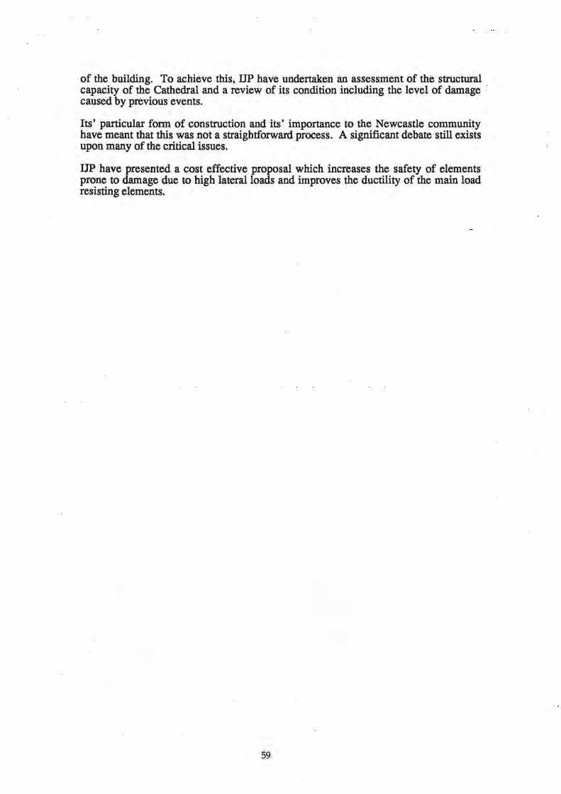
17. Southern transept and tower. The southern face appears to be totally undamaged by the 1989 earthquake.
18. North transept wall. Vertical cracks have occurred in the return walls of the transept, probably due to the earthquake. As will be discussed, these indicated the necessity to establish some ductility at the intersections. The north east tower turret had displaced 1mm over its 1400mm width. This was the only tower turret to display any damage.
19. Parapets. This is the parapet of the north western wall. Despite not being subjected to significant face loading, there has been some slight lateral displacement. The finals can be seen to have rotated on their central rod.
3. DAMAGE ASSESSMENT
As demonstrated by the slides, the Cathedral did not experience earthquake related damage to a significant amount of its structure. However, there were indications that parts of the structure, particularly the secondary elements, were prone to damage due to high lateral loads, presenting the possibility of partial collapse.
It was necessary to assess the capacity of the structure for lateral and longitudinal loads. We did this through a series of sensitivity computer models. The results have shown that despite the structure being mainly of solid masonry, and not containing an abundance of redundant features, it could sustain high loads without an excessive portion being highly stressed.
20. Eastern wall. This slide shows a finite element stress plot of the eastern wall. The colour coding providing the key to the stress level.
Two significant problems occurred after this phase:-
(a) What should be in input loading
(b) What should be the acceptable stress level.
The short answer is that both of these have yet to be resolved. Our position is that a loading level in the order of 0.15 g should be applied to the structure. This is approximately 50% greater than the Newcastle 1989 earthquake and in the order that can be developed by a rigorous application of the new earthquake code AS 1170.4, the United States UBC earthquake code for a similar intraplate location and close to the requirements for Auckland, New Zealand. It was determined that the model loading should be a function of the new code levels so that at least a "base" position could be developed.
The question of what should be acceptable stress level is fundamentally more difficult. This is because we are dealing with risk vs. money. Being an existing building, that is not being modified, just restored, it falls outside the specific legislation of the Australian Standards so that the decision needs to be achieved by consensus between the parties involved.
57

UP's criteria in developing a repair proposal based on our assessment of the structure was to:-
(a) Restrain elements prone to damage due to high lateral loads
(b) Increase ductility of the major load resisting elements
(c) General repairs of other elements.
To achieve this, IJP used a sliding scale of conformance levels to the Australian Standards. The rationale for this has been supported by practice in New Zealand, recommendations on existing building refurbishment by the Warren Centre and as presented by John Woodside during the recent lecture series for the launching of the new earthquake code.
21. Southern nave wall. This slide showing a preliminary restoration proposal for the southern nave wall highlights the above principles.
• The fmals, parapets and turrets are restrained from collapse by the insertion of new dowels
• The tower frame is tied into the adjacent arches
• The end walls are tied into the cross walls.
IJP envisage only a small proportion of the total structure requires reconstruction.
4. ALTERNATIVE VIEWS
Obviously, for a restoration proposal which contains many subjective elements, including public risk, there have been many alternate views. These have not all been resolved and should not be presented here in detail, suffice to say that they have concerned:
• The value of the design earthquake acceleration. This has been tied up with the life expectancy of the structure.
• What are acceptable stress levels within the structure and what is an acceptable damage extent during future events.
• The assessment of the current damage with reference to what force level caused it, what factor of safety did the element have during the event, what was the failure mechanism and whether it was even earthquake related.
• What upgrading or strengthening of the structure should be undertaken.
• What is an appropriate level of conservatism - or factor of safety that should be applied.
• Extent of restoration.
5. SUMMARY
IJP believe that it is important that the restoration of the Christ Church Cathedral Newcastle reflects the social issues of public risk vs. cost. The brief has been to advise the client of what is a reasonable and responsible level of restoration and strengthening
58
of the building. To achieve this, IJP have undertaken an assessment of the structural capacity of the Cathedral and a review of its condition including the level of damage caused by previous events.
Its' particular form of construction and its' importance to the Newcastle community have meant that this was not a straightforward process. A significant debate still exists upon many of the critical issues.
UP have presented a cost effective proposal which increases the safety of elements prone to damage due to high lateral loads and improves the ductility of the main load resisting elements.
59

6. SLIDES
Figure 1 - General view of East Newcastle Figure 2 - West wall
Figure 3- West Rose window Figure 4 - West wall turret
60

Figure 5- West wall damage Figure 6 - West wall flashing
Figure 7 - East wall Figure 8 - East wall interior
61

Figure 9 - Low east Figure 10- North wall "creep"
Figure 11- South arch repairs Figure 12 - North arch repair/exacerbation
62

Figure 13 - General interior Figure 14 - Northern arch
Figure 15 - Previous repairs to archway Figure 16 - Flying buttress
63
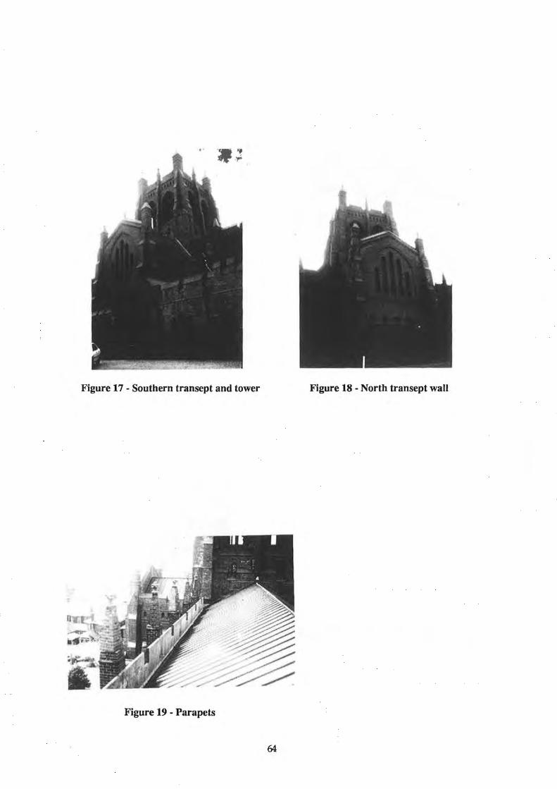
Figure 17 - Southern transept and tower Figure 18 - North transept wall
Figure 19 - Parapets
64

Newcastle Workers Club
I. Pedersen Connell-Wagner Rankine Hill, Newcastle, Australia
1. INTRODUCTION
The buildings that formed the Newcastle Workers Club were built in several stages. The section comprising of the eastern half of the building (white roof area) is the original structure while the westerly section (the darker collapsed section) was designed in 1970 and constructed soon after (figure 1).
At the time of the design of the western section of the building there was no requirement for earthquake design. The earthquake code current at the time of the earthquake was issued in 1979, approximately 9 years after the design of the western or collapsed section of the Workers Club.
In carrying out our investigation as to why a section of the Workers Club collapsed, we concentrated on the effects of earthquakes and we made no attempt to assess the structure against the relevant codes at the time of the 1970 design. Particularly as earthquake forces were not relevant to the design at that time.
The building as the name implies had been used exclusively as a Club with all the typical facilities that such complexes normally house. Minor interior alterations such as removal of toilet walls at the Mezzanine floor had occurred in the period 1972- 1989.
2. EXISTING STRUCTURE
We were not able to inspect the drawings of the eastern section of the building designed and constructed prior to the 1970's, but from our inspections and observations it was formed of load bearing walls, columns, beams and concrete floors.
However, we were able to inspect the drawings which were produced for the 1970's construction.
•
•
•
The 1970 or westerly section of the building is of reinforced concrete construction for all the suspended floors. The floor noted on the drawings as the balcony level is a solid reinforced concrete beams. The steel beams are fixed to the structural steel columns at the perimeter of the building with the internal support being in the form of RHS section hangers from the roof trusses. The reinforced concrete beams are either supported on reinforced concrete columns or at the perimeter of the building of loadbearing brickwork (figure 2).
The first three levels were waffle type slabs supported on reinforced concrete columns (figure 3).
The roof structure cousisted of metal sheeting supported on timber purlins which was in turn supported on structural steel trusses. The trusses are supported on structural steel columns. From the drawings it would suggest for lateral load, the resistance of roof level was to be provided by horizontal trusses in the plane of the roof which would transfer these loads to the walls in the direction of the load. From the balcony floor down the lateral loads would be distributed to the remaining structure in accordance with the stiffness of the various elements (figure 4).
67

• The western brick wall (figure 5) did not appear to have had any physical fixing to the balcony slab and lateral resistance was provided by cutting the bricks in between the flanges of the steel columns. At every sixth course of the brickwork steel plates were bonded into the brick mortar bed.
3. EARTHQUAKE
On Thursday, 28th December 1989, Newcastle was subjected to an intraplate earthquake that measured 5.6 on the Richter Scale. The earthquake although not large in magnitude, compared with those suffered by countries which are considered more earthquake prone. Because of its shallow nature, and the silty soil which comprises much of Newcastle's founding medium, the earthquake was amplified significantly over that normally associated with such a seismic event. My work as a Director of CERA, the Centre for Earthquake Research in Australia and the results of that work published in association with such people as Harold Stuart, Jack Rynn, Peter Hughes and ted Brennan by the New Zealand National Society for Earthquake Engineering, (a 96 page document) and the papers the same people presented at Memphis this year, outlines in detail our research and findings in this and many other factors in more detail. I commend the documents to you.
It is noted again that at the time of the design for the 1970's section of the Workers Club there was no current Australian Standard for earthquake design. Indeed the current Australian Standard AS2121, for earthquake design had Newcastle zoned as zero and thus there was still no statutory requirement to design for earthquakes in Newcastle. In making this zoning the seismologists, who assisted in formulating the AS2121, would appear to have assumed that the return period for likely earthquakes was such as not to warrant any acknowledgement in building design.
4. BUILDING INSPECTIONS
Because of immediate danger to the public I was unable to "freeze" the building to carry out a detailed inspection immediately after collapse and to analyse the cause of collapse. The rescue and recovery work I and others undertook has also been extensively covered in other papers, but in respect to this building I did concentrate on the structural elements, as it was my responsibility to make safe the structure whilst rescue was being undertaken. However, I would highlight the following items:
1. The punching shear failure at ground floor at the first line of columns adjacent to the west wall (figure 6).
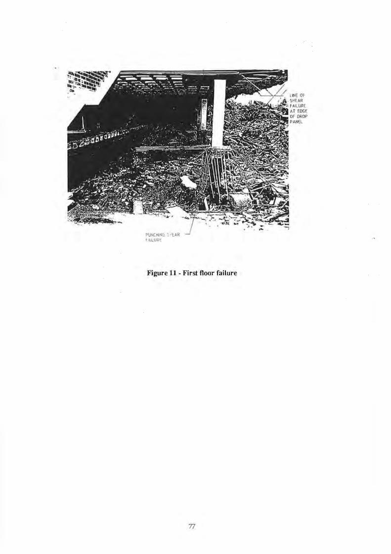
2. Shear failure at first floor level close to the western edge of the drop panel adjacent to the western wall was the area of major collapse and the area where most fatal injuries occurred (figure 7).
3. The attachment of the steel hangers to the bottom chord of the structural steel trusses.
4. The lack of any of the typical signs of damage to the structural steel columns normally associated with the failure of such members (figure 8).
5. The collapsed brick wall for almost the full extent of the western wall.
68

5. F AlLURE ANALYSIS AND DISCUSSION
Due to a lack of seismic instrumentation in the Newcastle Area it has not been possible to derive a possible design spectrum for the building.
However, in discussions with Dr Jack Rynn, Mr Kevin McCue and others it seems likely ground acceleration were in the range of 20% to 30%g. However, when considering elements in the upper levels of a building, whip effects due to building motion can magnify accelerations considerably in excess of those that apply at ground level.
For analysis of the western wall we have considered the western brick wall being supported in three ways:
i. Supported on three sides, i.e. the two vertical edges and at balcony level. The latter support condition can be considered somewhat tenuous, in that loads acting away from the building would drive no support here. However from observation, the walls did collapse out from and into the building and so we consider the assumption both reasonable and conservative.
n. Cantilevering above the balcony level.
iii. Spanning horizontally between the steel columns.
Brick walls subject to lateral loads are not capable of precise design and even though they are not isotropic there is an orthogonal strength ratio depending on the brick water absorption or the mortar used.
The only code we are aware of that does give design values, taking account of the orthogonal strength of brickwork is BS5628 Part 1 (2) and it was this code we used to assess the brick capacity rather than AS1640 (3). It should also be noted that BS5628 given ultimates strength values whereas ASI640 was strictly a working stress code.
Accordingly then the following values were used to establish the brick panel strength.
i. Mortar mix 1: 1 :6
ii. Water absorption between 7% and 12%
m. Characteristic flexural strength
a. Plane of failure perpendicular to bed joints b. Plane of failure parallel to bed joints
l.OMPa 0.35MPa
Using the above data the %g of failure load then for the three conditions of support are:
a. Supported on three sides b. Cantilevering above the balcony c. Spanning horizontally
0.5g 0.023g 0.4g
However, for the assumptions of a. and c. to be valid requires the reaction from the horizontal load to be either transferred through the brick that is cut between the column flanges or the frictional resistance of the brickwork bearing on the steel cleats (figure 9). We do not believe any reliability could be placed on the brickwork cut between the steel flanges as the very act of notching the stretcher course would in all probability have initiated a crack at the re-entrant angle. Accepting this statement then we believe the only reliable means of checking horizontal support is through the frictional resistance provided between the steel plate and the area of brickwork bearing on this
69

plate. Our calculations for the horizontal reaction show that the %g for failure now reduces to 10%g. From our calculation we believe the brick walls, due to a loss of lateral support, have failed at a level probably less than ground accelerations.
From calculations we found that the dynamic factor for a wall of the heights used falling onto the slabs of the stiffness detailed, is in the order of 20, which is greatly in excess of the dynamic factor of 2.5 (figure 10).
With the western wall failed the main auditorium (first) floor was then subject to the dynamic effects of these elements and our calculations show that shear failure would occur in the joist elements of the waffle slab in a line parallel to the west wall at approximately the junction of where the waffle slab meets the drop panel. Observations of the collapsed building confirm that this is where failure occurred in this slab (figure 11). We would add that our calculations indicate an even greater dynamic factor with the balcony and wall falling through a clear height of three metres.
The remaining slabs were then successively loaded from the floor above with the brittle punching shear failure occurring at the first line of columns in from the west wall. Again our calculations confirm this mode of failure.
6. CONCLUSIONS
Our calculations have been of a general nature and our assessments based on photographic evidence and observations. Following such an event and the need to save lives it is not possible to categorically state the exact cause of failure. We concluded that failure of the Workers Club was initiated through inadequate and brittle support to the brick wall on the western elevation. The collapse of this element of the building dynamically loaded the floor slabs well beyond their capacities and the fixing of its supporting members. The collapse of the first floor and balcony slabs in turn caused successive failure of the slabs below down through the height of the building.
7. THE LESSONS LEARNT
CERA has held several workshops and conferences involving professional engineers, local government personnel, rescue services such as SES, police, ambulance and the like. We have successfully communicated to those attending the consequences of an event such as an earthquake and the role of the professional engi.neer. It is a pity that the centres of our largest populations such as Sydney in particular and Melbourne appear to be ignoring the lessons. Smaller cities such as Brisbane, Darwin and Adelaide seem to be more interested. It is too late after the next event!
In closing, I leave you with my strategies for the future role of professional engineers in dealing with the mitigation of and preparedness for major disasters.
Strategies for Professional Engineering in the Mitigation of and Preparedness for National Disasters
• Training of engineers in emergency management.
• Publish through Institution of Engineers Australia a booklet on the role of the engineer in disasters.
• Implement a hazard mitigation program (also all infrastructure services) to define those structures or parts thereof that are susceptible to collapse from high consequence events (e.g. earthquakes, cyclones, wind/rainstorms)
70

• Establish data bank of engineers competent to handle management of and peer group review of other engineers before and/or after disasters occur.
• Provide maps of geology ("liquid soils"), flooding, access routes, evacuation areas etc., for use in every Council area.
• Priority - Identify and establish essential services and essential buildings for use in a disaster. Ensure structures (e.g. buildings, bridges), services and lifelines are OK to operate immediately after a major disaster.
• Establish network or association with engineers in other regions or countries who correspond and can back each other up in the first five to ten days following a disaster.
May I take this opportunity of thanking my partner, John Woodside from our Connell Wagner office in Adelaide for presenting this paper on my behalf.
8. REFERENCES
Standards Association of Australia, SAA Earthquake Code AS2121 - 1979.
British Standards Institution, Code of Practice for Structural Use of Masonry Part I, Unreinforced Masonry BS5628 1978 plus amendments.
Standards Association of Australia, SAA Brickwork Code AS1640- 1974.
Behaviour of Structures - Major Commercial Buildings, I.S. Pedersen, Institution of Engineers Australia, Newcastle Earthquake Conference.
The Newcastle Earthquake - The Engineers Perspective. I.S. Pedersen, Newcastle Division, The Australian Institute of Valuers.
The Newcastle Earthquake - The Behaviour of Buildings. I.S. Pedersen, Building Science Forum of Australia, NSW Division, Sydney.
The Newcastle Earthquake - Recovery Management. I.S. Pedersen, Institution of Engineers Australia, Management Branch, Canberra Division.
Newcastle Earthquake - The Basis for Engineering Design on Continental Australia. I.S. Pedersen and P.R. Hughes, Pacific Conference on Earthquake Engineering, Auckland, New Zealand.
Paper for Bulletin of the New Zealand National Society for Earthquake Engineering. The 1989 Newcastle, Australia, Earthquake: The Facts and Misconceptions. Rynn, Brennan, Hughes, Pedersen, Stuart.
Engineering Implications for Continental Earthquakes. Inference from the 1989 Newcastle, Australia, Earthquake. I.S. Pedersen and P.R. Hughes, 1993 National Earthquake Conference, Memphis USA.
71

9. FIGURES
Figure 1 - Aerial view of collapsed Workers Club
D ll .. ·-- ... ··-· ;- . ::0 :x: _ • _ ...... -·-· ·-
'""'1-c• ·~ , ••.• , ,., ...
Figure 2 - Building cross section
72

Figure 3- Waffie slab construction
Figure 4- Western wall failure
73

Figure 5- Western wall failure
Figure 6- Punching shear failure
74

Figure 7- Western wall failure
Figure 8- Western wall steel columns
75

Figure 9 - Brickwork failure
717171/ 1/
BRICK
Figure 10- Western wall failure
76
PUNCHiNG s~EAR F ~ILURc
Figure 11 - First floor failure
77