Duluth Airport Land Use Plan -...
64
i Duluth Airport Land Use Plan December 2001 Prepared by the Duluth-Superior Metropolitan Interstate Committee This study was funded through the Duluth-Superior Metropolitan Interstate Committee with funding from the: Federal Highway Administration Minnesota Department of Transportation Wisconsin Department of Transportation Arrowhead Regional Development Commission Northwest Regional Planning Commission Copies of this plan are available from the Duluth-Superior Metropolitan Interstate Committee 221 West First Street Duluth, Minnesota 55802 (218) 722-5545 Phone (218) 529-7592 Fax www.ardc.org Duluth-Superior urban area communities cooperating in planning and development through a joint venture of the Arrowhead Regional Development Commission and the Northwest Regional Planning Commission
Transcript of Duluth Airport Land Use Plan -...

i
Duluth Airport Land Use PlanDecember 2001
Prepared by theDuluth-Superior Metropolitan Interstate Committee
This study was funded through the Duluth-SuperiorMetropolitan Interstate Committee with funding from the:
Federal Highway AdministrationMinnesota Department of TransportationWisconsin Department of Transportation
Arrowhead Regional Development CommissionNorthwest Regional Planning Commission
Copies of this plan are available from theDuluth-Superior Metropolitan Interstate Committee
221 West First StreetDuluth, Minnesota 55802
(218) 722-5545 Phone(218) 529-7592 Fax
www.ardc.org
Duluth-Superior urban area communities cooperating in planningand development through a joint venture of the
Arrowhead Regional Development Commissionand the Northwest Regional Planning Commission

ii

iii
Duluth-Superior Metropolitan Interstate Committee
Member and Staff Listing
December 2001
Metropolitan Interstate Committee: Transportation Advisory Committee:
David Allen, City of Hermantown Jim Benning, City of DuluthEd Anderson, Superior City Council Jim Foldesi, St. Louis County (Chair)Nick Baker, City of Superior (WI Co-chair) Martin Forbes, WisDOTTom Brekke, St. Louis County SuburbanTwps John Foschi, City of Proctor (Vice-chair)Russell Carlson, Douglas County Board Paul Halverson, Douglas CountyMike Conlan, City of DuluthDavid Conley, Douglas County Board
Bryn Jacobson, Bike/PedestrianRepresentative
Bill Eckman, Douglas County Board Dennis Jensen, Duluth Transit AuthorityEarl Elde, St. Louis County Suburban Twps Dennis Johnson, MnDOTBob Finsland, Superior City Council Paul King, City of SuperiorFrank Ingram, Douglas County Suburban Twps Ray Klosowski, Duluth Airport AuthorityRichard A. Kieren, City of Proctor Richard Larson, City of DuluthDonny Ness, Duluth City Council Walter Leu, MnDOTIsobel Rapaich, Duluth Transit Authority Bill Majewski, City of DuluthCarol Reasbeck, City of Superior Mike Metso, City of Duluth Rob Stenberg, Duluth City Council (MN Co-chair) Joel Peterson, MPCAPeg Sweeney, St. Louis County David Salo, City of HermantownVacant, Douglas County Board Jason Serck, City of Superior
Ray Skelton, Duluth Seaway Port AuthorityARDC / MIC Staff: Vacant, Rail RepresentativeRon Chicka, MIC Director Vacant, Trucking RepresentativeHolly Butcher, PlannerConnee Kimball, InternAndy McDonald, Senior PlannerKirk Skoog, PlannerRondi Watson, Division SecretaryKendis Willet, Planner/GIS Specialist
NWRPC / MIC Staff:Sheldon Johnson, MIC Deputy Director
“Guiding the Future of Transportation and Planning for the Twin Ports Area”
DULUTH-SUPERIOR
METROPOLITAN INTERSTATE COMMITTEE

iv
Acronym Guide
ADT Average Daily TrafficALP Airport Layout PlanAOZ Airport Overlay ZoneARDC Arrowhead Regional Development CommissionASR Airport Surveillance RadarCAD Computer Aided DraftingCFR Code of Federal RegulationsCSAH County State Aid HighwayCFR Code of Federal RegulationsDAA Duluth Airport AuthorityDLH Duluth International AirportDNL Day-Night average sound LevelDOQ Digital Ortho QuadFAA Federal Aviation AdministrationFAR Federal Aviation RegulationGIS Geographic Information SystemsGPS Global Positioning SystemsINM Integrated Noise ModelIRC Interregional CorridorITE Institute of Transportation EngineersLdn symbol for DNLLOS Level of ServiceMIC Metropolitan Interstate CommitteeMMF Munitions Maintenance FacilityMNANG Minnesota Air National GuardMnDOT Minnesota Department of TransportationNCP Noise Compatibility ProgramNEM Noise Exposure MapNRRI Natural Resources Research InstituteSAW Single Additive Weighting modelTCE Trichloryll ethyleneTH Trunk HighwayTRANPLAN Computer model that simulates traffic circulationUSAF United States Air Force

v
TABLE OF CONTENTS
Chapter1: Introduction .............................................................................................1
Chapter 2: Data Collection.......................................................................................3
Chapter 3: Compatible Land Use Planning .............................................................5
Chapter 4: Noise Impacts.......................................................................................22
Chapter 5: Zoning Compatibility ...........................................................................27
Chapter 6: Strategies to Promote Compatible Land Uses .....................................32
Chapter 7: Airport Roadway Network...................................................................36
Chapter 8: Developable Land ................................................................................53
Chapter 9: Conclusion ...........................................................................................74
List of Tables, Figures, and Maps*
TablesTable 1: Safety Zone B Restrictions ......................................................................10
Table 2: Proposed Changes in Safety Zones A & B..............................................15
Table 3: AOZ Advisory Committee Recommendations........................................24
Table 4: Land Use Safety Zones - Compatibility Guidelines ................................35
Table 5: General Light Industrial – Trip Generation .............................................45
Table 6: Industrial Park – Trip Generation ............................................................45
Table 7: Manufacturing – Trip Generation............................................................45
Table 8: Input Attributes for SAW Model.............................................................53
FiguresFigure 1: Imaginary Surfaces.................................................................................11
Figure 2: Airport Road Traffic Counts ..................................................................39
Figure 3: Level of Service Descriptions ................................................................41
Figure 4: Airport Trailblazers ................................................................................48

vi
MapsMap 1: Duluth International Airport Location...........................................................1
Map 2: Current Land Use ..........................................................................................7
Map 3: Land Use Safety Zones..................................................................................13
Map 4: Proposed Changes in Safety Zones A & B for Runway 9-27 .......................17
Map 5: ASR & MMF Buffers....................................................................................15
Map 6: Proposed Runway 3-21 Extensions ...............................................................19
Map 7: Airport Overlay Zone and Noise Contours ...................................................25
Map 8: Airport Area Zoning ......................................................................................29
Map 9: Roadway Functional Classification...............................................................37
Map10: Miller Trunk Highway Implementation Plan Study Area ............................40
Map 11: TRANPLAN Roadway Model Results 1999 & 2025 .................................43
Map 12: Future Airport Area Roads ..........................................................................47
Map 13: Airport Area Roads to Monitor ...................................................................51
Map 14: Airport Wetlands .........................................................................................55
Map 15: Airport Parcels and Runway Restriction Areas...........................................59
Map 16: Developable Land........................................................................................61
Map 17: Duluth Airport Development Areas ............................................................63
Map 18: North Development Area No-Build and Electronic Free Buffers ...............58
Map 19: North Development Area Brownfields........................................................65
Map 20: North Development Area Wetlands ............................................................67
Map 21: North Development Area Water Line Cost/Distance Analysis...................69
Map 22: North Development Area Sewer Line Cost/Distance Analysis...................71
Map 23: Growth Risk Area........................................................................................75
*The information on the maps in this document are a compilation of data from various federal, state,county, regional, and municipal sources. Geographic information has limitations due to the scale,resolution, date and interpretation of the original source materials. Users should consult available datadocumentation (metadata) to determine limitations and the precision to which the data depicts distance,direction, location or other geographic characteristics. These maps and/or data are not legal surveydocuments to be used for describing land for the purpose of ownership or title.

1 Duluth Airport Land Use Plan
Canosia Township
Rice Lake Township
Hermantown
Duluth(/5 3
(/2
LaVaque R
oad
Ugstad Road
Ric
e L a
ke R
oad
W. Arrowhead Road
Trunk Highway 53
LaVaque R
oad
Martin Road
Haines Road W. Arrowhead Road
Runway 3-27
#
#
Runway 9-21
eTerminal
LaVaq
ue B
y-Pass
Duluth International Airport
CHAPTER 1: INTRODUCTION
The Duluth International Airport is a regional resource that provides our area with accessto air travel anywhere in the world, as well as jobs for the region. The airport, located inthe northwest area of Duluth, is surrounded by three jurisdictions: the City ofHermantown, Canosia Township, and Rice Lake Township, which in turn havesignificant stakes in how land is developed in and around the airport. Therefore, aregional approach to airport development is needed, as well as an effective system for thefour jurisdictions, along with St. Louis County, to communicate information about allnew developments that may impact the airport. This regional approach to airportplanning and development will allow the four jurisdictions to grow without adverselyimpacting the airport.
The public has an interest in protecting airports to allow them to function in an efficientmanner. Airports generate a large amount of economic activity in addition to providingfor the movement of people, goods, and services. It would be difficult and expensive toreplace or relocate an existing airport on a comparable site within proximity to an urbanarea. For this reason, it is extremely important to achieve long-term compatibilitybetween the airport operations and nearby land uses. Planning for compatible land usesis an attempt to make the best use of limited community resources.
Map 1
2
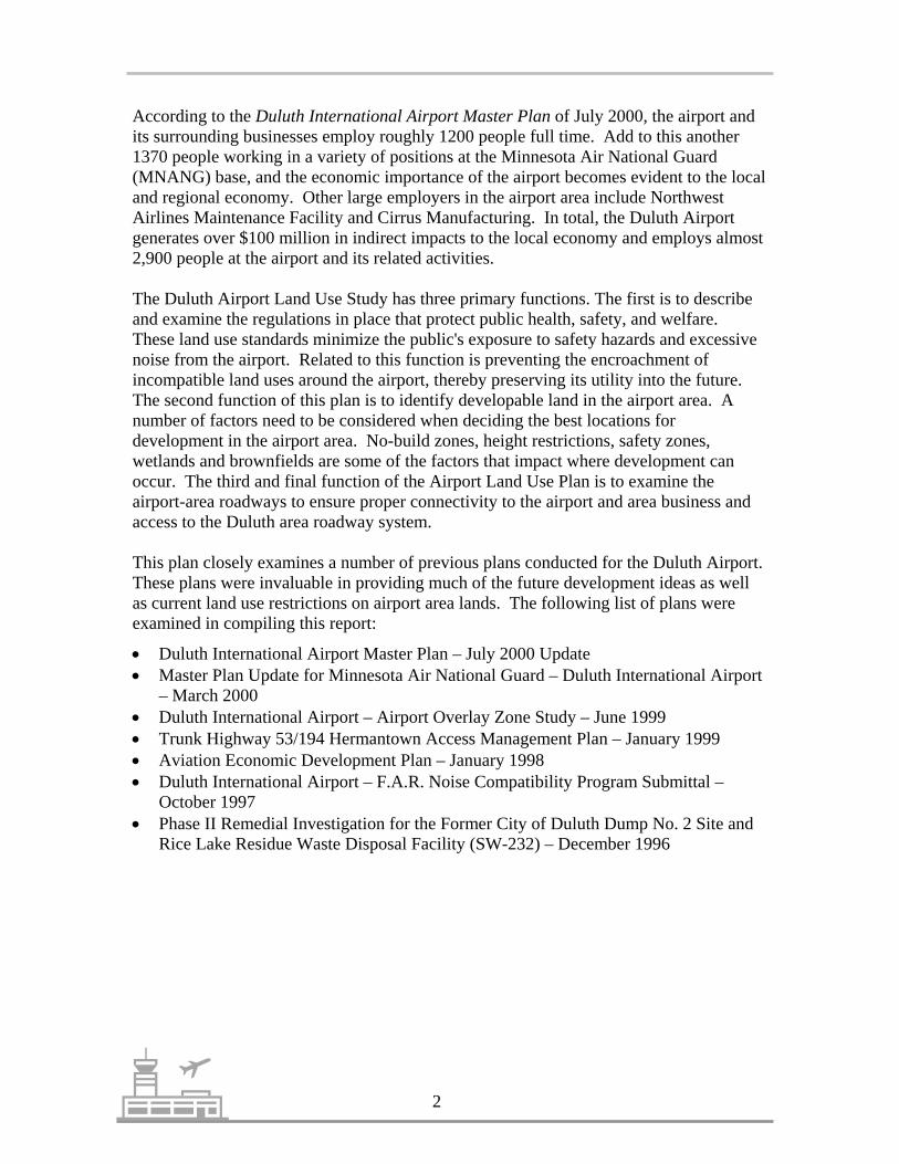
According to the Duluth International Airport Master Plan of July 2000, the airport andits surrounding businesses employ roughly 1200 people full time. Add to this another1370 people working in a variety of positions at the Minnesota Air National Guard(MNANG) base, and the economic importance of the airport becomes evident to the localand regional economy. Other large employers in the airport area include NorthwestAirlines Maintenance Facility and Cirrus Manufacturing. In total, the Duluth Airportgenerates over $100 million in indirect impacts to the local economy and employs almost2,900 people at the airport and its related activities.
The Duluth Airport Land Use Study has three primary functions. The first is to describeand examine the regulations in place that protect public health, safety, and welfare.These land use standards minimize the public's exposure to safety hazards and excessivenoise from the airport. Related to this function is preventing the encroachment ofincompatible land uses around the airport, thereby preserving its utility into the future.The second function of this plan is to identify developable land in the airport area. Anumber of factors need to be considered when deciding the best locations fordevelopment in the airport area. No-build zones, height restrictions, safety zones,wetlands and brownfields are some of the factors that impact where development canoccur. The third and final function of the Airport Land Use Plan is to examine theairport-area roadways to ensure proper connectivity to the airport and area business andaccess to the Duluth area roadway system.
This plan closely examines a number of previous plans conducted for the Duluth Airport.These plans were invaluable in providing much of the future development ideas as wellas current land use restrictions on airport area lands. The following list of plans wereexamined in compiling this report:
• Duluth International Airport Master Plan – July 2000 Update• Master Plan Update for Minnesota Air National Guard – Duluth International Airport
– March 2000• Duluth International Airport – Airport Overlay Zone Study – June 1999• Trunk Highway 53/194 Hermantown Access Management Plan – January 1999• Aviation Economic Development Plan – January 1998• Duluth International Airport – F.A.R. Noise Compatibility Program Submittal –
October 1997• Phase II Remedial Investigation for the Former City of Duluth Dump No. 2 Site and
Rice Lake Residue Waste Disposal Facility (SW-232) – December 1996

3 Duluth Airport Land Use Plan
CHAPTER 2: DATA COLLECTION
This plan contains numerous Geographical Information System (GIS) data layers, whichwere used for analysis throughout the plan. The data originated from a variety offormats, including hard copy maps, computer aided drafting (CAD) files, data created byother agencies and consultants, and global positioning system (GPS) data. The finaledited, digital form was incorporated into ArcView GIS for analysis. This chapter brieflydescribes the central data layers used in the plan. A more detailed description of the datalayers is presented within each chapter.
A full metadata record has been created for all of the following data and will be storedwith the electronic files for this project. Metadata is a written record that describes themost important facts about a data set. It is critical for data creators to record vitalinformation about the data set in order to organize and maintain the data. Metadata isequally important to those who share data and need clear and complete information aboutdata they are considering using. Contact MIC staff for access to the metadata records forthis plan.
Parcels Parcel information for the study area was gathered from engineering parcel maps. Eachparcel was converted into digital format following strict accuracy standards. The finallayers were edge-matched and compiled into one seamless parcel map.
Land UseThe land use data layer was comprised of three different layers: the City of Duluth (1995-2000), the City of Hermantown (1997), and Arrowhead Regional DevelopmentCommission(1992) land use classifications. The layers were combined to form oneseamless layer to identify land use and/or zoning conflicts, as well as uses suitable fordevelopment.
Zoning
Four zoning maps were compiled into a final zoning map for the plan. Maps wereobtained from Hermantown (1992), Rice Lake Township (1998), City of Duluth, andCanosia Township (1998).
Wetlands
The Natural Resource Research Institute (NRRI) completed a detailed wetlanddelineation study using photography from 1997 and 1995. The color infrared photoswere utilized in delineating wetlands in the airport area. Wetland classifications followedthe U.S. Fish and Wildlife Service conventions for the National Wetlands Inventory.
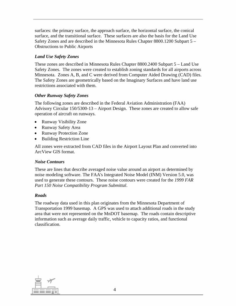
Imaginary SurfacesThe Federal Aviation Administration (FAA) has developed standards for the allowableheights of objects near airports in the Code of Federal Regulations (CFR) “ObjectsAffecting Navigable Airspace.” This regulation is defined by a series of imaginary
4
surfaces: the primary surface, the approach surface, the horizontal surface, the conicalsurface, and the transitional surface. These surfaces are also the basis for the Land UseSafety Zones and are described in the Minnesota Rules Chapter 8800.1200 Subpart 5 –Obstructions to Public Airports
Land Use Safety ZonesThese zones are described in Minnesota Rules Chapter 8800.2400 Subpart 5 – Land UseSafety Zones. The zones were created to establish zoning standards for all airports acrossMinnesota. Zones A, B, and C were derived from Computer Aided Drawing (CAD) files.The Safety Zones are geometrically based on the Imaginary Surfaces and have land userestrictions associated with them.
Other Runway Safety ZonesThe following zones are described in the Federal Aviation Administration (FAA)Advisory Circular 150/5300-13 – Airport Design. These zones are created to allow safeoperation of aircraft on runways.
• Runway Visibility Zone• Runway Safety Area• Runway Protection Zone• Building Restriction Line
All zones were extracted from CAD files in the Airport Layout Plan and converted intoArcView GIS format.
Noise ContoursThese are lines that describe averaged noise value around an airport as determined bynoise modeling software. The FAA's Integrated Noise Model (INM) Version 5.0, wasused to generate these contours. These noise contours were created for the 1999 FARPart 150 Noise Compatibility Program Submittal.
Roads
The roadway data used in this plan originates from the Minnesota Department ofTransportation 1999 basemap. A GPS was used to attach additional roads in the studyarea that were not represented on the MnDOT basemap. The roads contain descriptiveinformation such as average daily traffic, vehicle to capacity ratios, and functionalclassification.
5 Duluth Airport Land Use Plan
CHAPTER 3: COMPATIBLE LAND USE PLANNING
Compatible land use planning near airports requires examining a number of issues,including object height restrictions, potential for aircraft accidents and areas of frequentaircraft overflight. Airport land use regulations allow for the safe operation of aircraft toand from the airport and to protect people living and working near airports. This chapterwill examine current land use in the Duluth Airport area, airport-related land use zonesand regulations, future airport changes that may impact land use, and potential changes inairport land use regulations in Minnesota.
Current Land UseA number of factors influence how land is used in any given area. Land use controls,economic markets, proximity to other land uses, availability of access, location ofutilities, and environmental conditions affect how land is developed or not developed.Currently the areas adjacent to the airport are experiencing vastly different levels ofdevelopment. The Trunk Highway 53 area south of the airport is experiencing densehighway related developments, whereas the areas north of the airport are mostly openspace. The following discussion illustrates the current land use in the airport area (seeMap 2) and attempts to identify some of the forces that may have influenced particularuses.
The area north of the airport is mostly open space with some industrial and residentialuses. This area contains the North Development Area (see Chapter 8), the location ofNorthwest Airlines Maintenance Facility, which has been identified as an area for futureindustrial/manufacturing development. This area has a new access road, North StebnerRoad, which extends approximately 1.3 miles south of Martin Road through CanosiaTownship to the Northwest facility site. The utilities to the Northwest facility extendfrom the south, therefore, any new development along North Stebner Road would requireutility extensions.
Along Martin Road between Lavaque Road and Rice Lake Road, a number single-familyhomes are located there along with one small area of light industry. The land on thesouth side of the road falls within Duluth, Rice Lake, and Canosia. The land on the northside of the road is Rice Lake and Canosia. Currently, this area has seen little growthbecause of the lack of utilities and the presence of numerous wetlands.
At the intersection of Rice Lake Road and Martin Road, a variety of commercial andresidential uses exist. This area may see additional development pressure, as plans callfor a sewer extension to this area. The land in the southeast quadrant of the intersectionhas been cleared to ready the site for development. Other property at this intersection hasrecently changed hands with plans for more intensive use publicized.
South of Martin Road along Rice Lake Road, there is a mix of uses with some residential,commercial, and industrial. The land along the east side of the road is relativelyundeveloped with scattered residential areas and a former auto salvage yard. TheWLSSD Industrial Landfill and the former Duluth Dump Site #2 are located west of Rice

6
Lake Road and accessed by Ridgeview Road. A number of environmental issues havebeen connected to the former uses of these sites and monitoring wells are currentlylocated in this area to monitor ground water contamination. The area directly east ofRunway 9-27 along Rice Lake Road is mostly open space due to its proximity to therunway.
Southeast of the airport terminal area, along Haines Road and Airport Road, AirparkIndustrial Park serves a mix of commercial and industrial uses. Airpark is anapproximately 200 acre site which currently has 36 businesses and over 400 employees.Directly south of the airport terminal area is mostly open space with some industrial andresidential land uses along Swan Lake Road.
Trunk Highway 53 is the location of intensive commercial development in the airportarea. This mostly auto-related development consists of a wide variety of uses frombar/restaurants to theaters to mobile home/recreational vehicle sales. The majority ofthese uses developed because of their proximity to the highway. Development has spreadnorthwest up the highway after development of the Miller Hill area in the 1970s and1980s. Development is more compact along Trunk Highway 53 until Lavaque Road.From Lavaque Road to the west and north along the highway development thins out.
The South Redevelopment Area, as identified in the Aviation Economic DevelopmentPlan, is located directly south of Runway 9-27. This area is a preferred location ofaviation-related businesses and the redevelopment of buildings from the former U.S. AirForce Base. The Airport Road/Airport Approach Road/Stebner Road loop serves theSouth Redevelopment area and also bounds the Federal Prison Camp. The prison alsoutilizes a large number of former airbase buildings for their facility. This area is also thelocation of Cirrus Designs, an aircraft manufacturer specializing in smaller privateaircraft. The recent connection of Airport Road with Airport Approach Road and theremoval of some of the former airbase buildings have opened up this area for more lightindustrial and manufacturing development.
The area to the west of the airport property north of Trunk Highway 53 is mostly openspace and residential. Much of this area falls within the runway safety area, withassociated development restrictions.
Runway Safety AreasAll airports in Minnesota are required to designate areas around their runways as safetyzones. The location and size of the zones depend on the length of the runway and theaircraft that are operating on the runways. Airport safety zone areas serve two primarypurposes; they provide a safe environment for aircraft operating in the vicinity of anairport and also provide a safe environment for community members living and workingnear airports. Rules defining these safety areas have been developed nationally by theFederal Aviation Administration and statewide by the Minnesota Department ofTransportation – Office of Aeronautics.

����������� ��������������
����������
���������������
�����
����
����������������������
����������
�����
���� !
���
��"��
����
���
�
�������������� �����
#���������
����������� ���
����������
���������������
�����
����
����������������������
����������
��"��
����
���
�
�
������������ �
���������� ����� ���������� �� ��� ����� ������������������������������������ ��� �� ���!��� ��"�������������#����� ���$���%������&�'������� ���
�����
�����(��������)����� ���
����
* + �� �
�������������(���������,�������,� �(����������-
������,�.� ����������(�������&�"�(������/�.$0�
����1

8
Airspace ProtectionThe Federal Aviation Administration (FAA) has set standards to maintain aircraft safetyin areas around airports. These standards limit the height of objects near airports tominimize safety hazards for aircraft. The Code of Federal Regulations (CFR) Title 14Part 77 “Objects Affecting Navigable Airspace” defines a system of imaginary surfacesaround an airport through which no fixed object or structure should penetrate. Thesesurfaces are designed to allow safe operation of aircraft in and around airports.
An object is considered a general obstruction to air navigation if it is greater than 500 ftabove ground level at its location. Also considered an obstruction is an object 200 ft.above ground level or airport elevation within three nautical miles of the recognizedreference point at the airport and that height increases 100 feet for every nautical milefrom the airport to a maximum of 500 ft. An object is considered an obstruction to apublic airport if it penetrates one of the imaginary surfaces described in the Code ofFederal Regulations (CFR) Title 14 Part 77 (see Figure 1 – Imaginary Surfaces).MnDOT – Department of Aeronautics has adopted these imaginary surfaces anddescribes them in Minnesota Rules Chapter 8800.1200 Subpart 5. These surfaces differin size depending on the type of runway landing instrumentation that is available at anairport. The following descriptions of the imaginary surfaces include what is currentlypresent at the Duluth Airport.
The primary surface is a rectangular surface at runway elevation and centeredlongitudinally on the runways. The elevation of any point on the primary surface is thesame as the elevation of the nearest point on the runway centerline. The primary surfaceat the Duluth Airport is 1,000 ft. wide and extends 200 ft. past the end of each runway.
The approach surface is trapezoidal in shape and slopes upward and outward fromeither end of the primary surface. It begins at the end of each primary surface and climbsat a slope of 50:1 for the first 10,000 ft and 40:1 for the next 40,000 ft.
The horizontal surface is a geometric plane 150 ft. above the runway that is defined byarcs swung 10,000 ft. from the end point of each runway and connected by tangent lines.
The conical surface slopes up and away from the perimeter of the horizontal surface at aslope of 20:1 for a horizontal distance of 4,000 ft.
The transitional surface extends laterally up and away from the lateral edges of theprimary and approach surfaces at a slope of 7:1.
Airport Land Use Safety ZonesAccording to Minnesota Rules 8800.2400, use restrictions are placed on certain zones toprotect operational safety of aircraft and life and property of the general public. Thesesafety zones create sufficient open space in case of an accident to protect the community.General restrictions that apply to the safety zones include: no land use shall createelectronic interference for aircraft or the airport, produce lights that make it difficult for
9 Duluth Airport Land Use Plan
pilots to see airport lights, or otherwise endanger aircraft landings, takeoffs andmaneuvering. The following Land Use Safety Zones (see Map 3) are based on theimaginary surfaces explained earlier in this section and have land use restrictionsassociated with them.
Safety Zone A is the most restrictive of the zones and is located in the approach zones ofa runway, extending outward from the end of the primary surface a distance equal to two-thirds the runway length or planned runway length.
Safety Zone A shall contain no buildings, temporary structures, exposed transmissionlines, or other similar land use structural hazards, and shall be restricted to those useswhich will not create, attract, or bring together an assembly of persons thereon.Permitted uses may include, but are not limited to, such uses as agriculture (seasonalcrops), horticulture, raising of livestock, animal husbandry, wildlife habitat, light outdoorrecreation (nonspectator), cemeteries, and auto parking.
This zone is primarily a clear zone as it basically includes an extended area that coversthe runway ends.
Safety Zone B is less restrictive than Safety Zone A and is located in the approach zonesof a runway, extending outward from Safety Zone A to a distance equal to one-third therunway length or the planned runway length.
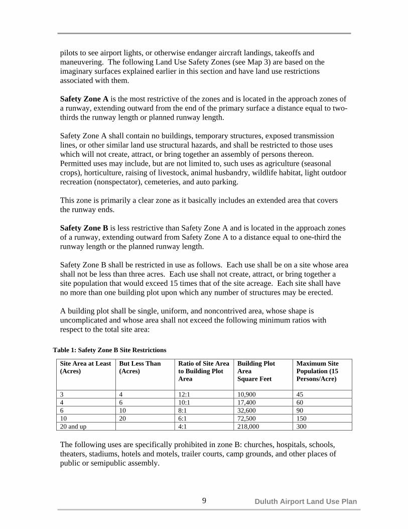
Safety Zone B shall be restricted in use as follows. Each use shall be on a site whose areashall not be less than three acres. Each use shall not create, attract, or bring together asite population that would exceed 15 times that of the site acreage. Each site shall haveno more than one building plot upon which any number of structures may be erected.
A building plot shall be single, uniform, and noncontrived area, whose shape isuncomplicated and whose area shall not exceed the following minimum ratios withrespect to the total site area:
Site Area at Least(Acres)
But Less Than(Acres)
Ratio of Site Areato Building PlotArea
Building PlotAreaSquare Feet
Maximum SitePopulation (15Persons/Acre)
3 4 12:1 10,900 454 6 10:1 17,400 606 10 8:1 32,600 9010 20 6:1 72,500 15020 and up 4:1 218,000 300
The following uses are specifically prohibited in zone B: churches, hospitals, schools,theaters, stadiums, hotels and motels, trailer courts, camp grounds, and other places ofpublic or semipublic assembly.
Table 1: Safety Zone B Site Restrictions

Three Dimensional View
20:1
7:1
7:1
40,000’40:1
10,000’50:1
7:1
40:1
50:1
Runway Centerline
Top View
Primary Surface
Approach Surface
Horizontal Surface
Conical Surface
Transitional Surface
Imaginary Surfaces
Figure 1

� �
�
�
����
���� �����
�����
�������
�����
���������
��������
���������
���������
�����
������
����� �����
����� ����
!��������
�
��
�
�
�
�
�
�
�
�������������� ����
�
�����
� � � ���

12
Safety Zone C is the least restrictive of the three Safety Zones and is described as theland, which is enclosed within the perimeter of the horizontal zone. Safety Zone C is
subject only to the general restriction described above.
Potential Changes in Safety Zones in MinnesotaMnDOT has proposed changes in the airport zoning language in the Minnesota Rules.The proposed changes include changes in the lengths of Safety Zones A and B. Currentlythese zones, when combined, are equal in length to the runway they are associated with.The proposed rule changes would establish safety zones that are generally less restrictivethan current standards. The table below outlines the proposed changes in the total lengthsof Safety Zones A and B combined. If implemented, these changes would not take placeuntil 2002.
Table 2: Proposed Changes in Safety Zone A & B Total Length Runway Length(L) Safety Zone A and B Combined Length
Up to 5,000 feet Runway Length (L)5,000 feet to 9,000 feet 5,000 feet + 50% (L - 5,000 feet)Greater than 9,000 feet 7,000 feet
Based on the combined lengths of Safety Zones A and B, Safety Zone A would be 2/3 ofthe total runway length and Safety Zone B would be 1/3 of the total runway length. Forexample, any runway over 9,000 feet in length will have a Safety Zone A that is 4,669feet in length and a Safety Zone B that is 2,331 feet in length. At the Duluth InternationalAirport, these proposed changes would not impact the current runway 3-21 but wouldshorten Safety Zones A and B for Runway 9-27 to 7,000 feet in length (from their currentlengths of 9,520 feet for Runway End 9 and 10,240 for Runway End 27 (see Map 4)).Future expansion of Runway 3-21 would be impacted by these changes if the expandedlength is greater than 5,000 feet.
Other Duluth International AirportBuffer Zones
There are currently two facilitieslocated on the airport property thatalso require safety buffers (see Map5). The Minnesota Air NationalGuard (MNANG) MunitionsMaintenance Facility (MMF) and theAirport Surveillance Radar (ASR)require buffers to ensure their safeoperation. The MMF, operated bythe MNANG, requires a 1,250 footno-build buffer. This buffer has beenestablished to provide a safe zone forthe storage of munitions on the site.Future plans call for a relocation ofthis facility to the east of the
Map 5

13 Duluth Airport Land Use Plan
MNANG base. The ASR requires a 1,500 foot no-build zone and a ½ mile electronic-free zone. These two zones ensure no interference and safe operation of the ASR. Futureplans also outline a need to move the ASR to accommodate future development.
Potential Runway Expansion ProjectsThe Duluth International Airport Master Plan determined that the existing runwaysystem could accommodate projected aviation demand through 2020. However,improvements to the existing runways should be considered. These improvementsinclude an extension to the main runway (9-27) to accommodate future large aircraftoperations as well as an extension to the crosswind runway (3-21) to satisfy crosswindrunway requirements. The Master Plan identifies a number of alternatives for expandingthe length of these runways. The plan illustrates three alternatives for extending Runway9-27 and six alternatives for extending Runway 3-21. The following text describes thepreferred alternative as stated in the Master Plan and highlights some of the potentialimpacts to surrounding land uses and future land uses in the area.
Runway 9-27Runway 9-27, the east-west runway, is the main runway at the Duluth Airport andhandles most of its air traffic. The preferred short-term alternative as identified in theDuluth International Airport Master Plan would use the Declared Distance Concept* togain use of 1,000-foot of overrun pavement east of the relocated threshold on Runway 27for 11,152 foot takeoffs to the west. Declared distances for airport design is an optionthat can be used where it is impracticable to provide the runway safety areas. This optionwould require a number of improvements to the east end of the runway. Theseimprovements include relocating existing landing area lighting, reconstruction of existingtaxiways and construction of a 400’ X 220’ blast pad which would force the relocation ofHaines Road to the east.
Runway 3-21Runway 3-21 is the northeast-southwest crosswind runway. FAA rules state thatcrosswind runways should be 80% of the main runway length. The preferred extensionalternative identified in the Duluth International Airport Master Plan proposes toconstruct a 3,259 foot runway extension on the northeast end of Runway 21 bringing thetotal length to 8,122 feet. Due to the existence of residential and commercialdevelopment along both sides of Miller Trunk Highway at the southwest end of Runway3-21, runway extension options are planned to the northeast. This alternative would alsorelocate the threshold on Runway 3 to 1,106 feet northeastward. Again, relocating this
*Declared Distance is used in existing constrained airports where it is impractical to provide the runway safety area, the runway objectfree area, or the runway protection zone. The declared distances are takeoff run available (TORA), takeoff distance available (TODA),accelerate-stop distance available (ASDA), and landing distance available (LDA). By treating the airplane’s runway performancedistances independently the airport can provide for different design methodologies by declaring distances to satisfy the airplane’s takeoffand landing requirements. When taking into consideration the actual needs of the aircraft, the runway design can change and will affectthe beginning and ending of the runway safety area, runway object free area, and the runway protection zone.

14
Martin Road
LaVaque R
oad Arrowhead Road
N. S
tebn
e r R
oad
Airport Road
Haines R
oad
Ugstad R
oadR
ice L
ake R
oad
%g194(/53
N
(/5 3 %g1 94
Airport Road
Airpark Boulevard
West end of runway 9-27 East end of runway 9-27
Proposed Changes in Safety Zones A&B for Runway 9-27
#
Runway 9-27
Proposed Safety Zone ChangesA
B
Existing Land Use Safety ZonesA
B
Runway Roads
Legend
* Safety Zone C not shown
0.5 0 0.5 Miles
Map 4
4669'2331' 2331'
4669'

15 Duluth Airport Land Use Plan
(/53 %g194
Rice
Lak
e Roa
dU
gstad Road
Haines R
oad
Arrowhead RoadLaV
aque Road
Airpark Boulevard
Martin Road
N.
Ste
bne
r R
oa
N
Marti n Road
Ri dgev iew Road
St
eb
ne
r
Ro
Ri
ce
L
ak
e
R
Arrowh ead Ro ad
%g194
(/53
North end of runway 3-21 South end of runway 3-21
Proposed Runway 3-21 Extension
#
Runway 3-21
218 7
'
4374
'
#
Proposed RunwayExtension
Present Runway
Runway 3-21 Extension
Existing Land Use Safety ZonesA
B
Proposed Safety Zone ChangesA
B
Roads
Legend
0.5 0 0.5 1 Miles
Map 6*Safety Zone C not shown

17 Duluth Airport Land Use Plan
threshold is necessary so Safety Zones A and B would not impact businesses along TrunkHighway 53. The proposed runway extension would provide an 8,122 foot runway whilenot affecting the location of Runway 3 Safety Zones A & B to the southwest. Thisalternative also utilizes the proposed changes in MnDOT’s length requirements for SafetyZones A and B (see Map 6).
Extension of Runway 3-21 would also mean moving Safety Zones A & B to thenortheast, which would impact existing land uses and potential development in Rice LakeTownship. Under this proposal, Safety Zone A would cross Martin Road and extend tothe northeast. The newly located Safety Zone A would encompass an existing residentialarea along the south side of Martin Road. Safety Zone B would extend beyond SafetyZone A to the northeast and partially cross Rice Lake Road. This land is currently zonedresidential, non-shoreland commercial, and multiple-use non-shoreland. The 1998 RiceLake Township Comprehensive Plan identifies land along Martin Road for future use asindustrial and land along Rice Lake Road as commercial and industrial uses.
CONCLUSION
Land use can be a potentially controversial issue when jurisdictions are being told whatthey can and can’t do with their land. However, given the economic importance of theDuluth airport to this region and the cost that other airports have incurred to deal withland use compatibility issues, all area jurisdictions should make every attempt to preventincompatible land use in the airport vicinity. A particular goal of this study is toencourage compatible land uses in the airport area in order to protect the community, itstaxpayers, and the economic viability of the area, while minimizing any burden to currentproperty owners.
Local comprehensive plans and zoning ordinances for those communities located near theairport should be reviewed, and, if necessary, amended to incorporate recommendationsaddressing compatible land uses and developments. In areas adjacent to the airport, landuses should be compatible with the role and function of the airport while maintainingexisting compatible community uses.

18
CHAPTER 4: NOISE IMPACTS
Most complaints concerning airports are related to noises generated by aircraftoperations. At low levels, noise in the area around an airport is normally tolerated;however, as exposure to noise increases, it begins to interfere with sleep, conversation,school, business, and recreational activities. The effect of noise interference on normalactivities is most often described in terms of annoyance.
Given that airports represent a substantial investment of public funds, cooperative effortsto mitigate noise impacts are extremely important. All airports are required by the FAAto plan for noise impacts. The Duluth International Airport has undertaken two recentplanning efforts in an attempt to develop strategies to decrease the impact to adjacentcommunities from aircraft noise. The Federal Aviation Regulation Part 150 Studyconducted by ACSG of Naperville, IL and adopted in June of 1999 and the AirportOverlay Zone Study conducted by ACSG and the MIC and adopted by the MIC in Juneof 1999 provide the Duluth Airport with guides on how to plan for noise compatible landuses.
Federal Aviation Regulation (FAR) Part 150 StudyThe purpose of the FAR Part 150 Study was to develop a Noise Compatibility Program(NCP) for the Duluth Airport which will review and recommend various noise abatementand mitigation measures based upon the Noise Exposure Map (NEM). The goal of thisstudy is to “identify areas of noise land use incompatibility around DLH, develop noiseabatement alternatives to mitigate existing incompatibilities, and recommend actions toprevent future incompatibilities, while taking under consideration the costs andeffectiveness associated with various alternatives proposed.”
FAR Part 150 guidelines dictate how the NEM was created. On-site noise measurements,runway and flight track geometry, approach and departure profiles, operational activityand complaints from neighbors were used as inputs to generate noise contours for 1996and a five year forecast at 2001. Development of this map has produced a model ofwhere different levels of noise are present. Using these contours and local land use, theNEM identifies areas of incompatible land use that are of concern. The NEM developedfor the Duluth Airport area specifically identified areas of incompatible land uses in the65 DNL and higher noise levels.
DNL is defined as a level of noise derived by measuring average sound levels in a 24hour day, in decibels. Nighttime noise, between the hours of 10:00 p.m. and 7:00 a.m. isweighted; that is, given an additional 10 decibels to compensate for sleep interference andother disruptions caused by loud nighttime noise. For airport noise exposure purposes, anannual average sound level is used. 65 DNL is the noise threshold at which the FAAdefines an area “compatible with residential use; areas at or above 65 DNL are designatedas “incompatible with residential use.”

19 Duluth Airport Land Use Plan
The Noise Compatibility Program, in turn, seeks to address these areas that wereidentified by the Noise Exposure Map by providing an overview of operational noiseabatement measures that may be implemented by the airport sponsor, as well aspreventative land use measures that may be introduced by local planning and zoningjurisdictions. These options include immediate and long-term measures. Examples ofairport sponsor noise mitigation measures include takeoff and approach procedures, noisebarriers, acquisition of land, curfews, landing fees based on noise levels, and denial ofaircraft not meeting federal noise levels. Strategies that local governments can use tolessen noise impacts include acquisition of impacted land, sound insulation, developmentcontrol, zoning, easements, and transfer of development rights.
FAR Part 150 requires that the NCP is developed in coordination with local planningofficials, aviation and airport officials, along with other interested parties. This shouldinsure that mitigation measures that are brought forth are realistic and acceptable to theaffected jurisdictions.
The NCP recommended measures for implementation, which included both noiseabatement procedures and land use alternatives. The recommended noise abatementprocedures included creating a noise abatement committee, efforts by MNANG and theair traffic control to route flights away from dense residential areas, and a feasibilitystudy into extending runway 3-21. Recommended land use alternatives included avoluntary land acquisition strategy for properties inside the 65 DNL contour withemphasis on those inside the 75 DNL contour and strong proactive position toward futurenon-compatible land uses.
Airport Overlay Zone (AOZ) Study One option identified by the FAR Part 150 Study to prevent future noise impact areas isthe development of a new special zoning district called an airport overlay zone. Thesezones are normally created as an alternative to attempting to change existing zoning. Theoverlay zone is superimposed on existing zoning districts and is intended to supplementthe noise regulations of the general purpose zoning districts. Even if existing zoning ischanged in noise-impacted areas from residential to include manufacturing or industrialuses, it does not prohibit residential uses in those areas. The overlay zone can adopt moreperformance driven standards, which may help lessen the impact of incompatible uses orprevent future incompatible uses. The overlay zone technique can also be more sensitiveto established communities and neighborhoods by not forcing a land use change fromresidential to commercial or industrial.
The Airport Overlay Zone Study conducted by the MIC and ACSG adopts themethodology and conclusions from the FAR Part 150 Study and examines the land useissues in greater detail. It detailed land use in the airport area on a parcel level andprovided an accurate picture of development issues. Five zones were examined: theentire study area, and the 60, 65, 70, 75 DNL contours (see Map7). Each of these zoneswas examined to identify current land uses and how much vacant land is available forfuture development.
20
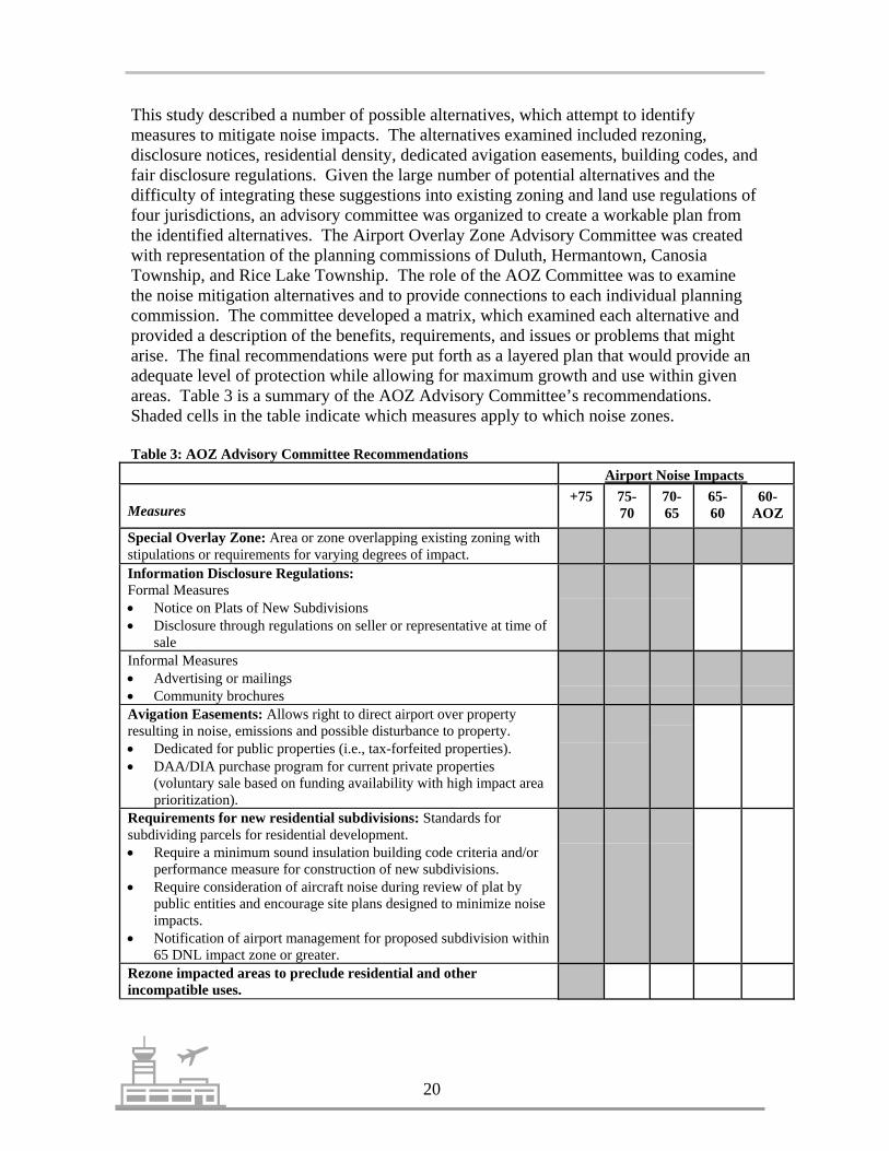
This study described a number of possible alternatives, which attempt to identifymeasures to mitigate noise impacts. The alternatives examined included rezoning,disclosure notices, residential density, dedicated avigation easements, building codes, andfair disclosure regulations. Given the large number of potential alternatives and thedifficulty of integrating these suggestions into existing zoning and land use regulations offour jurisdictions, an advisory committee was organized to create a workable plan fromthe identified alternatives. The Airport Overlay Zone Advisory Committee was createdwith representation of the planning commissions of Duluth, Hermantown, CanosiaTownship, and Rice Lake Township. The role of the AOZ Committee was to examinethe noise mitigation alternatives and to provide connections to each individual planningcommission. The committee developed a matrix, which examined each alternative andprovided a description of the benefits, requirements, and issues or problems that mightarise. The final recommendations were put forth as a layered plan that would provide anadequate level of protection while allowing for maximum growth and use within givenareas. Table 3 is a summary of the AOZ Advisory Committee’s recommendations.Shaded cells in the table indicate which measures apply to which noise zones.
Table 3: AOZ Advisory Committee RecommendationsAirport Noise Impacts
Measures+75 75-
7070-65
65-60
60-AOZ
Special Overlay Zone: Area or zone overlapping existing zoning withstipulations or requirements for varying degrees of impact.Information Disclosure Regulations: Formal Measures • Notice on Plats of New Subdivisions• Disclosure through regulations on seller or representative at time of
saleInformal Measures • Advertising or mailings • Community brochuresAvigation Easements: Allows right to direct airport over propertyresulting in noise, emissions and possible disturbance to property.• Dedicated for public properties (i.e., tax-forfeited properties).• DAA/DIA purchase program for current private properties
(voluntary sale based on funding availability with high impact areaprioritization).
Requirements for new residential subdivisions: Standards forsubdividing parcels for residential development.• Require a minimum sound insulation building code criteria and/or
performance measure for construction of new subdivisions. • Require consideration of aircraft noise during review of plat by
public entities and encourage site plans designed to minimize noiseimpacts.
• Notification of airport management for proposed subdivision within65 DNL impact zone or greater.
Rezone impacted areas to preclude residential and otherincompatible uses.

�����
�������
�� �����
����� ���
���������
�����
������
�
�����������
����������
���������
���������
����
���������
�
������������ ������������������
� � � � ����
����� ����������������������������
��������������
�� ���
���
���� �
�� ��

22
CHAPTER 5: ZONING COMPATIBILITY
Zoning ordinances and comprehensive plans (where available) were examined for thecities of Duluth and Hermantown and the townships of Rice Lake and Canosia to see howthese communities control land use and plan future development near the Duluth Airport.A short description of each community’s zoning ordinance and zoning maps as theypertain to the airport area is contained in this section. A description of the Airport ZoningBoard zoning ordinance is also included. Comprehensive plan information from eachcommunity is included if there is specific language or vision for areas adjacent to theairport.
All zoning from the jurisdictions was mapped to analyze the composite Duluth Airportarea. The Airport Zoning Board’s zoning was also mapped and overlaid onto the basezoning layer (see Map 8). A brief description of the zoning categories from eachjurisdiction that fall into the Land Use Safety Zones is also included.
Canosia TownshipThe majority of land within Canosia Township that is in proximity to the airport is zonedMultiple Use Non-Shoreland. This category allows a wide range of uses, some of whichrequire performance standards and other uses which require conditional use permits. Thereis also a small commercial district near Lavaque Bypass and Samuelson Road and aresidential zone south of Wild Rice Lake. The land uses allowed in these zoning districtsare compatible with those that are allowed in Safety Zone C. However, large scaleresidential development is not encouraged within Safety Zone C.
In 1995, Canosia Township updated its Comprehensive Plan in anticipation of new impactsfrom the development of the Northwest Airlines Maintenance Facility and a potentialextension of a sewer line to the Pike Lake area. One of the development goals calls forconsolidating similar land uses for economic reasons such as provision of services. Toaccomplish this goal, the township identified the newly built access road, North StebnerRoad, as a location for commercial and industrial development. Another policy set forth inthis plan is to “participate as a member of the Joint Airport Zoning Board” to allow inputfrom Canosia residents on airport related issues. The Comprehensive Plan states that theairport is an important facility to the residents of the township. Canosia Township iscurrently in the process of updating its Comprehensive Plan.
Rice Lake TownshipRice Lake Township has zoned much of the area around Rice Lake Road as commercial orindustrial. Other zoning districts in the airport area include Multiple Use Non-Shorelandand Residential. Although Rice Lake’s zoning is compatible with the current Land UseSafety Zones, this area may soon be experiencing pressure to develop.
In its 1995 Comprehensive Plan, the township identified future commercial and industrialland uses for the Martin Road and Rice Lake Road corridors. Recent news reports suggestthat the township is interested in extending water and sewer to the intersection of Martin
23 Duluth Airport Land Use Plan
and Rice Lake Roads. If these utility extensions take place, it will bring developmentpressure to this area.
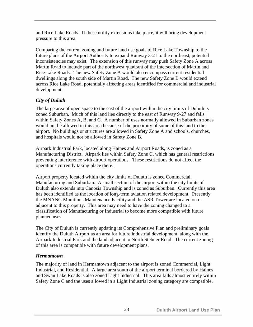
Comparing the current zoning and future land use goals of Rice Lake Township to thefuture plans of the Airport Authority to expand Runway 3-21 to the northeast, potentialinconsistencies may exist. The extension of this runway may push Safety Zone A acrossMartin Road to include part of the northwest quadrant of the intersection of Martin andRice Lake Roads. The new Safety Zone A would also encompass current residentialdwellings along the south side of Martin Road. The new Safety Zone B would extendacross Rice Lake Road, potentially affecting areas identified for commercial and industrialdevelopment.
City of Duluth The large area of open space to the east of the airport within the city limits of Duluth iszoned Suburban. Much of this land lies directly to the east of Runway 9-27 and fallswithin Safety Zones A, B, and C. A number of uses normally allowed in Suburban zoneswould not be allowed in this area because of the proximity of some of this land to theairport. No buildings or structures are allowed in Safety Zone A and schools, churches,and hospitals would not be allowed in Safety Zone B.
Airpark Industrial Park, located along Haines and Airport Roads, is zoned as aManufacturing District. Airpark lies within Safety Zone C, which has general restrictionspreventing interference with airport operations. These restrictions do not affect theoperations currently taking place there.
Airport property located within the city limits of Duluth is zoned Commercial,Manufacturing and Suburban. A small section of the airport within the city limits ofDuluth also extends into Canosia Township and is zoned as Suburban. Currently this areahas been identified as the location of long-term aviation related development. Presentlythe MNANG Munitions Maintenance Facility and the ASR Tower are located on oradjacent to this property. This area may need to have the zoning changed to aclassification of Manufacturing or Industrial to become more compatible with futureplanned uses.
The City of Duluth is currently updating its Comprehensive Plan and preliminary goalsidentify the Duluth Airport as an area for future industrial development, along with theAirpark Industrial Park and the land adjacent to North Stebner Road. The current zoningof this area is compatible with future development plans.
HermantownThe majority of land in Hermantown adjacent to the airport is zoned Commercial, LightIndustrial, and Residential. A large area south of the airport terminal bordered by Hainesand Swan Lake Roads is also zoned Light Industrial. This area falls almost entirely withinSafety Zone C and the uses allowed in a Light Industrial zoning category are compatible.

���������
����
���
���
����
���������������������� �������� �
����� ������������
������� ��������
����� ����
����� ����������������� ������������
�
�� ������
�
������� ��������
�
!�� ������
�
����� �����������"� ��#
�
�� �������$�%�&���' �������
�
(�����
�
�� �)������ &��������
������������� �������� ���
�
' �������
������ ����
�
%�&���' �������
���� ���
�������
���������
���� �
�
������������� ������� ����������������� ������������������������������ ��������������� ���������������� �������������� ��������������� ������� ����������������� ��! �������"#�� ����� ��! �������"#�� ���"$�� ��! �������"#�� ���"%���"#�� ����������� &!��#!��'�( ��'�( ��)�� ��! �������"#��*+������� +������� �,-.),..+������� �/-%)/..+������� �%-.)0..+������� ��� ��"���� �#����������#�� ������1�����#�(�(����������
21���������������#� ��������3�
+�����
+����
��4�
#����
����
�����������������
/ . / $ �� �
��!�5

25 Duluth Airport Land Use Plan
A large amount of the land adjacent to Trunk Highway 53 is zoned as Commercial andfalls into Safety Zones A, B, & C. Almost all commercial uses are disallowed in Safety
Zone A, while Safety Zone B specifically prohibits theaters, stadiums, hotels, and motels.Commercial uses along this corridor are compatible with Safety Zone C.
Residential zoning districts within Hermantown fall into Safety Zones B and C.Residential uses incompatible with Safety Zone B include trailer parks and other denseresidential developments.
Duluth International Airport Zoning OrdinanceThe jurisdictions surrounding the Duluth Airport have created a Joint Zoning Board toregulate the use of property in the vicinity of the Duluth Airport. The jurisdictions formingthe Duluth International Airport Joint Zoning Board are Duluth, Hermantown, CanosiaTownship, Rice Lake Township, and St. Louis County. The Duluth International AirportZoning Ordinance, created by the Joint Zoning Board, was adopted in June 1988 andrevised in May 1996.
The Airport Zoning Ordinance restricts the height of buildings and objects and regulatesthe use of property in the vicinity of the Duluth Airport. Airspace obstruction zoning isaccomplished through the use of the Airspace Zones that are associated with the ImaginarySurfaces described Chapter 3. No tree shall be allowed to grow or structure built thatwould penetrate any of the Imaginary Surfaces.
Land use regulation is accomplished through the creation of the airport Safety Zones.Safety Zones A, B, and C, described in Chapter 3, were created to protect the generalpublic on the ground and provide space for emergency landings for aircraft. Userestrictions are associated with each zone and are more restrictive near areas of aircraftoperation (such as the ends of each runway). A study of civil aircraft accident patterns bythe University of California at Berkley has shown that most aircraft accidents near airportshappen on or near the extended runway centerline. Limitations to the types of land usesand the density of structures in these areas provide for safer airport operation. The AirportZoning Ordinance describes the location of each Safety Zone and the types of uses anddensities that are allowed. The Duluth International Airport Zoning Ordinance takesprecedence over the zoning ordinances of the four adjacent jurisdictions.
The Airport Zoning Ordinance contains six maps that make up the official Airport ZoningMap and include the Imaginary Surfaces Plan, the Imaginary Surfaces Sections, HeightLimitation Zoning Plan, Land Use Safety Zones, Detailed Land Use Safety Zones, andLand Ownership – Safety Zones A & B of Runway 3.
In addition, the Airport Zoning Ordinance includes information on non-conforming uses,permits, variances, and administration. A Board of Adjustment is also established by theordinance and is comprised of one member from the cities of Duluth and Hermantown, theDuluth Airport Authority, and the Townships of Rice Lake and Canosia. The Board ofAdjustments hears and decides appeals and grant variances, with decisions made bymajority vote.
26
CHAPTER 6: STRATEGIES TO PROMOTE COMPATIBLE LAND USE
Most airports were developed outside of urbanized areas on flat land that was usuallysurrounded by agricultural or undeveloped land. As cities grew outward, the landsurrounding airports began to be developed, which, combined with increased air traffic,led to incompatible land uses. Whether due to noise or safety issues, encroachingdevelopment is forcing communities to make choices about balancing airport operationswith development location decisions. A number of strategies exist to help communitiesdevelop compatible land uses on land adjacent to airports. Some of the followingstrategies are also outlined in the Duluth International Airport Overlay Zone Study.
Land AcquisitionIf incompatible land uses exist or result from an airport expansion, the airport operatormay attempt to obtain the incompatible properties. Normally, land acquisition is used forproperties that fall into present or future runway protection zones or primary approachsurfaces. The State of Minnesota also allows the use of eminent domain bymunicipalities to purchase property for airport uses.
Advanced Property AcquisitionPurchasing land in advance of development may be a method to acquire properties beforedevelopment pressures inflate the cost of the land. Public acquisition before land costsincrease represents potential savings in future purchase costs, which should offset thelong-term interests of the purchase. Once in public ownership, the airport can lease theland for compatible uses. Land needed only for airport protection, not for futureexpansion, can be resold to the public with deed restrictions that would prohibitincompatible land uses.
EasementsAn easement is a right of another party to part of the benefits of the ownership of realproperty. Easements are purchased from a property owner and allow the purchaserproperty rights for the special purposes stated in the purchase agreement.
An avigation easement is the purchase of the rights to the airspace above a piece ofproperty. This right allows the airport operator to direct flights over the property andprohibits the property owner from using the land for structures higher than a specifiedheight. It also addresses dust, noise, vibration, and light and radio wave restrictions. Therestrictions will vary in accordance with the airspace necessary for the safe use of theairport’s runways.
As a preventative measure, an avigation easement may be obtained as a condition ofdevelopment approval. This would require a developer to dedicate an easement beforetheir development application could be approved. This also allows the avigationeasement to act as a fair disclosure notice, since the easement becomes a permanent deedrestriction and a part of the legal record.

27 Duluth Airport Land Use Plan
Fair Disclosure NoticeA fair disclosure notice is an informative notice implemented in either a formal orinformal manner, which conveys to interested parties the potential for noise or safetyimpacts on properties in proximity to the airport. Formal measures may include therecording of a notice on plats of new subdivisions or a requirement that fair disclosure beimplemented which require the seller to provide notice of safety or noise impacts at thetime of the property sale. Informal measures may include mailings of disclosure noticesor distribution of brochures to a community.
Land Use RegulationsLand use regulation is a power allowed by federal and state laws to promote and protectthe public health, safety and welfare. Community plans are partially implementedthrough the enforcement of land use regulations. The regulations used in airport planningnormally include zoning, plat and subdivision review, and building codes.
Land Use ZoningZoning is the most common form of land use control. It designates areas of thecommunity most suitable for certain land uses. A couple of strategies exist within thecontext of zoning. An area can be rezoned to preclude incompatible uses or performancemeasures can be introduced into zoning codes to reduce potential incompatible uses.Rezoning impacted areas to eliminate residential uses will promote compatible land usessuch as commercial, industrial, agricultural, or recreational uses. Performance standardssuch as minimum lot sizes and reduced housing densities may reduce the numberpotentially impacted residences but does not provide for a true compatible use.
An Airport Overlay Zone is another method of zoning that promotes compatible landuses around an airport. This method mostly addresses the issue of noise impacts onsurrounding land uses. The zone is determined by noise exposure contours, which aredeveloped by recording noise levels and modeling the results to form lines of equal noiselevels. Land use restrictions are tied to each different noise level zone. The MIC, inconjunction with ACSG, Inc. prepared the Airport Overlay Zone Study for the DuluthAirport Authority in June 1999.
Building CodesBuilding codes are one strategy to alleviate noise impacts. After noise impact areas aredefined, municipal building codes should be amended to require soundproofing of newstructures built in these areas. These can be incorporated into local zoning codes.
Plat and Subdivision ReviewThe purpose of plat review is to regulate the subdivision of land to promote public health,safety, and general welfare. Plat review can sometimes be limited to ensuring propersubdivision and design engineering of land while not examining nearby land uses. Platand subdivision review is not as effective as zoning to insure land use compatibility,however, it does provide an opportunity to prevent incompatible land uses. Plat andsubdivision review should establish standards for site planning, lot layout, infrastructure

location, and public improvements. This review process would be an opportune time toconsider other measures to ensure compatible land use near the airport, such as avigationeasements or disclosure notifications.
Plat review is most useful if noise impacted areas and safety zones are identified on theplat map. This can provide official notice that the property is subject to use restrictionsand noise impacts.
Land Use Compatibility GuidelinesA number of sources were considered in developing basic guidelines for compatible landuses in airport areas. The Denver Regional Council of Governments developed anAirport Compatible Land Use Design Handbook that provides guidance for compatibleland use planning around airports. WisDOT has developed A Guide for Land UsePlanning Around Airports to provide planners, policy makers, and airport administratorsa tool to improve land use compatibility between airports and neighboring communities.Information contained within these documents and the Minnesota Rules Chapter8800.2400 and the FAA Advisory Circular 150/5300-13 were combined to develop acompatibility matrix. This matrix (see Table 4) lists Safety Zones A, B, & C andidentifies the acceptability level of specific land uses (see Map 3 for the locations of theSafety Zones).
CONCLUSION
The strategies listed above are not exhaustive, but provide a list of commonly used andeffective tools to prevent incompatible land uses near airports. Each community adjacentto an airport can decide which strategies would work best for them to ensure safecoexistence with the airport. The key to mitigating existing compatibility issues andplanning compatible land uses in the future will most likely be found in cooperativeefforts by the airport operator and surrounding communities.
28

29 Duluth Airport Land Use Plan
Table 4: Land Use Compatibility Guidelines Safety Zone Land Use Category A B CResidential Single-family -- - O2
Multi-family, apartments, condominiums -- - O2
Public Schools, libraries, hospitals -- -- - Churches, auditoriums, concert halls -- -- - Transportation, parking, cemeteries ++ ++ ++
Commercial and Industrial Offices, retail trade -- O1 +2
Service commercial, wholesale trade, warehousing, light industrial
-- +1 ++2
General manufacturing, utilities, extractive industry -- +1 ++2
Agricultural and Recreational Cropland ++ ++ ++ Livestock breeding ++ ++ ++ Parks, playgrounds, zoos + + ++ Golf courses, riding stables, water recreation + + ++ Outdoor spectator sports -- -- O 2
Amphitheaters -- -- O 2
Open space ++ ++ ++
++ Clearly Acceptable: The activities associated withthe specified land use will experience little or noimpact due to airport operations. Disclosure of airportproximity should be required as a condition ofdevelopment.
- Normally Unacceptable: Specified use shouldbe allowed only if no reasonable alternativeexists. Disclosure of airport proximity andavigation easements should be required as acondition of development.
+ Normally Acceptable: The specified land use isacceptable in this zone or area. Some residents mayperceive impact. Disclosure of airport proximityshould be required as a condition of development.Dedication of avigation easements may be advisable.
-- Clearly Unacceptable: Specified use must notbe allowed. Potential safety or overflightnuisance impacts are likely in this area.
O Marginally Acceptable: An impact will beperceived as a result of allowing the specified use inthis zone or area. Disclosure of airport proximity andavigation easements should be required as a conditionof development.
1 Acreage, building size and site population must meet regulations of item C, Subp. 6 (Use Restrictions-Zone B),Minnesota Rules-chapter 8800.2400.2 Must meet general restrictions contained in item A, Subp. 6 (Use Restrictions), Minnesota Rules-chapter8800.2400.

30
CHAPTER 7: AIRPORT ROADWAY NETWORK
The roads in the airport area provide access to the main airport terminal and to thebusinesses that are located on airport property. This system of roads provides access toand from the Duluth Airport and surrounding businesses for customers, employees, anddeliveries of goods and services. Maintaining the integrity of this road system isimportant. This section examines the elements of the local road system. Circulation,access, capacity, functional classification, connectivity, and future roadway needs are theelements of the airport area road network that are examined in this section.
Local Circulation The Duluth Airport area roadway network consists of system of functionally classifiedroads that provide access and connection to the U.S. Interstate system (see Map 9). Eventhough different areas of the airport are not connected by internal roads (excludingtaxiways), the adjacent roads provide timely access. The functionally classified roads inthe Duluth Airport area include Trunk Highway 53 (Principal Arterial), Lavaque Bypass(Major Collector), Martin Road (Minor Arterial), Rice Lake Road (Minor Arterial),Airport Road (east section – Minor Arterial), Haines Road (Minor Arterial), andArrowhead Road (Minor Arterial). A recent addition to the functionally classed system isthe Stebner-Airport Approach-Airport Road loop that begins at Stebner Road and TrunkHighway 53 and loops back to Trunk Highway 53 at Airport Road. This loop, recentlyclassified as a Major Collector, includes a newly completed gravel section of AirportRoad, which connects to Airport Approach Road.
Access and Connectivity Access and connectivity to major highways for airport businesses is important to theeconomic well-being of the area. Access as it is used here can be defined as the links tothe adjacent functionally classified roadway system. Connectivity can be described asthe connection to the areas major highways. Access and connectivity are critical for theeconomic health and competitiveness of the airport--businesses located on the airportproperty have to be able to send and receive materials by road in a cost efficient andtimely manner. Attracting new businesses to locate at the airport also requires high-quality access and connections to major highways.
In general, access is sufficient to most areas of the airport. Access to the general terminalis by the Grinden Drive loop from the intersection of Airport Road and Haines Road.The intersection has a four-way stop sign and experiences little or no congestion. Accessto the Minnesota Air National Guard (MNANG) facility is from the same intersection onan extension of Haines Road. MNANG officials would like to change this access toaccommodate proposed internal circulation changes and the development of a new maingate. The new access would accommodate future expansion plans for Runway 9-27 andimprove security at the MNANG facility.

31 Duluth Airport Land Use Plan
Ugstad Road
Airport Road
Arrowhead RoadLaVaque Roa d
Martin Road
%g194(/53
Rice
Lak
e Roa
dU
gstad Road
Haines Road
Airport Road
N. S
tebn
er R
oad
LaVaque Roa d
N
Functionally Classified Roadways
Functional Classification
Interstate Highway
Major Collector
Minor Arterial
Minor Collector
Principal Arterial
local
Runway
Legend
1 0 1 2 Miles
Map 9

32
Access to the North DevelopmentArea, where Northwest Airlines
Maintenance Facility is located, isby North Stebner Road. This road
was built to specifically accessNorthwest’s facility and connectswith Martin Road (CSAH 9). Theconnection to Martin Road is an
uncontrolled T-shaped intersectionthat has right and left turn lanes on
Martin Road to accommodate surgesin traffic during shift changes.
The Southern Redevelopment Area(see Chapter 8), until recently, hadtwo separate primary access pointsoff of Trunk Highway 53. With therecent connection of Airport Road to Airport Approach Road via a new gravel connector,a loop road system exists that allows vehicles access to Trunk Highway 53 at twodifferent intersections. Traffic destined for the eastern areas of Duluth do not have to useTrunk Highway 53. From Airport Approach Road, traffic may use Airbase Road toaccess Arrowhead Road. Recent traffic counts along the gravel section of Airport Roadindicate that almost 400 vehicles used this connection over a 24-hour period and over 900vehicles used the connection over a 48-hour period (see Figure 2).
The three major areas of the airport,(the terminal area, the NorthDevelopment Area, and the SouthRedevelopment Area) are alllocated within proximity to TrunkHighway 53. Trunk Highway 53provides an excellent connection tothe Iron Range of Minnesota aswell as Canada to the north.Connections to I-35 and pointssouth are not as clearly defined.Trunk Highway 53 is connected toI-35 via Miller Trunk Highway tothe southeast or via TrinityRoad/Piedmont Avenue and downthe hill to I-35. This route is one ofthe more congested routes in theDuluth-Superior area, although byurban area standards it still flowsfairly well. Truck traffic may wish to avoid this route based on higher amounts of trafficand the general topography of the route. Trucks proceeding to the airport from I-35 south
1 2
3
Location 24 Hr Count 48 Hr Count1 1,526 3,3742 393 9063 1,123 2,412
$
$
$
Miller Trunk Highway
Stebn er Road
Airport RoadA
irpor
t App
roac
h R
oad
Figure 2 - AirportRoad TrafficCounts
New gravelconnector
Gravel Connector – Airport Road

33 Duluth Airport Land Use Plan
Map 10
and southeast of Miller Trunk Highway experience significant grades and changes inelevation. For example, from the Proctor area along I-35 to the Trunk Highway 53interchange, vehicles drop approximately 600 feet in elevation. From the I-35/TrunkHighway 53 interchange to Haines Road and Trunk Highway 53, vehicles gain just over700 feet in elevation. An alternate route from I-35 to the airport utilizes Midway Road(CSAH 13) to Maple Grove Road (CSAH 6) to Stebner Road. This route follows twolane roads with lower amounts of traffic and less severe topography.
A better roadway connection from the airport to I-35 would help future development andexisting businesses at the Duluth International Airport. However, the costs for a limitedaccess roadway from the airport to I-35 would be extremely expensive. Given the currentresidential development patterns in Hermantown and Western Duluth neighborhoods,along with the challenging topography, it would be extremely difficult to create a newroadway.
A study currently underway that will improve access and connectivity to Trunk Highway53 is the Miller Trunk Highway Implementation Plan (see Map 10). This study is part ofthe Interregional Corridor (IRC) program, a statewide effort designed to maintain themost important state highway corridors. The Miller Trunk project will utilize a numberof studies that have been completed over the years. These studies include the 1992 and1995 Miller Hill Corridor Studies and the 1999 Hermantown Highway 53/194 AccessManagement Plan. Thegoal of the IRC program isto maintain or decreasetravel times through thecorridor. The Miller TrunkHighway ImplementationPlan will identify solutionsto bottleneck problemsthroughout the corridor.Possible solutions includefrontage roads, laneadditions, intersectionimprovements, local roadimprovements, signalcoordination, andzoning/land use controls.These strategies should helpreduce congestion in theTrunk Highway 53 corridorand provide better accessbetween the airport and I-35.

34
Capacity AnalysisIn the development of the 2001-2025 Long Range Transportation Plan Tomorrow’sTransportation 2025, the MIC examined system level deficiencies throughout theDuluth-Superior roadway system. The travel demand model TRANPLAN was used tosimulate regional traffic flows for the base year, in this case 1999, and then it modeled forecasted traffic for the year 2025. Inputs into the model include average daily traffic(ADT), socio-economic data, new housing starts, new businesses, and projected areas ofgrowth. The results help to determine impacts of growth on the future transportationsystem.
One output of the modeling process is a quantifiable measurement of current andprojected roadway capacity deficiencies. Roadway capacity refers to acceptable trafficvolume on a roadway given its specific design. A capacity deficiency is defined as a highvolume to capacity (v/c) ratio. The volume to capacity ratio is based on capacities thatwere calculated for a Level of Service (LOS) “C”. A v/c ratio of 1 indicates a roadwayoperating at LOS C, which is defined in Figure 3 by stable traffic flow with speeds andmaneuverability closely controlled due to traffic volumes. However, at LOS C theroadway is still capable of serving more vehicles. Larger urban areas use a LOS of “D orE” when examining volume to capacity ratios. Drivers in larger urban areas are moretolerant of congestion. When a road reaches 100% of its designed capacity, congestion islikely to occur. The TRANPLAN model indicates where congestion is likely to occurbased on demographic trends. This information helps in monitoring areas where futureroad improvements may be needed.
A
B
C
D
E
FREE FLOW. Low volumes and no delays.
Level of Service Description
STABLE FLOW. Speeds restricted by travelconditions, minor delays.
STABLE FLOW. Speeds and maneuverabilityclosely controlled due to traffic volumes.
STABLE FLOW. Speeds considerably affected bychange in operating conditions. High-density trafficrestricts maneuverability, volume near capacity.UNSTABLE FLOW. Low speeds,considerable delay, volume slightly overcapacity.FORCED FLOW. Very low speeds, volumesexceed capacity, long delays with stop-and-gotraffic.
F
Figure 3: Levels of Service Descriptions

35 Duluth Airport Land Use Plan
The following LOS characteristics correspond to v/c ratios:• LOS A-C corresponds to v/c ratios from 0.0 to 1.0• LOS D corresponds to v/c ratios from 1.0 to 1.15• LOS E corresponds to v/c ratios from 1.15 to 1.25• LOS F corresponds to v/c ratios greater than 1.25
This analysis focuses on the model results in the Duluth Airport area. The model results(see Map 11) indicate that capacity deficiencies may occur in 2025 on Haines Road fromTrunk Highway 53 to Airport Road. This may be the result of projected growth atAirpark Industrial Park and potential growth at MNANG. Capacity deficiencies are alsoforecast for Rice Lake Road from Airport Road to Martin Road, due to the projectedgrowth in the airport area as well as in the townships north of Duluth. A short section ofTrunk Highway 53 from Stebner Road to Arrowhead Road is also projected to experiencecapacity deficiencies. Projected growth in this area, combined with continued growth inthe townships to the north, may produce these results. The model results should beviewed with caution as he TRANPLAN model uses a number of inputs and assumptionsand any change in growth patterns can impact the model results. Roadways with capacitydeficiencies identified for 2025 should be monitored and patterns of growth observed toprovide a proactive plan to maintain good traffic circulation in the airport area.
Trip GenerationEconomic development efforts for the airport property have identified specific areaswhere certain types of development should take place. Given this outline of identifiedfuture land uses, development scenarios can be generated to examine the impact on theadjacent roadway network. One tool that can be used is trip generation rate predictions.Trip generation is defined as the number of vehicles generated by a unit of land use.Scenarios can be created that would predict the number of employees or square footageof identified land uses and trip generation rates applied to get an idea of the amount oftraffic each type of development can generate.
The generation rates used in this section were taken from the Trip Generation, 6thEdition published by the Institute of Transportation Engineers (ITE). This document wasdesigned specifically to assist transportation professionals in predicting how many tripsmay be generated by a particular land use.
The following land uses were used in this analysis (land use code numbers from the ITETrip Generation Manual are also shown):
• General Light Industrial (110)• Industrial Park (120)• Manufacturing (140)
Most of the aviation-related development and non-aviation related developmentidentified as desirable for the airport property fall within the above land uses. CirrusDesigns falls into the Manufacturing land use category and the Northwest AirlinesMaintenance Facility falls into the General Light Industrial category. Expansion ofcurrent business could also use these land use categories to predict future traffic impacts.
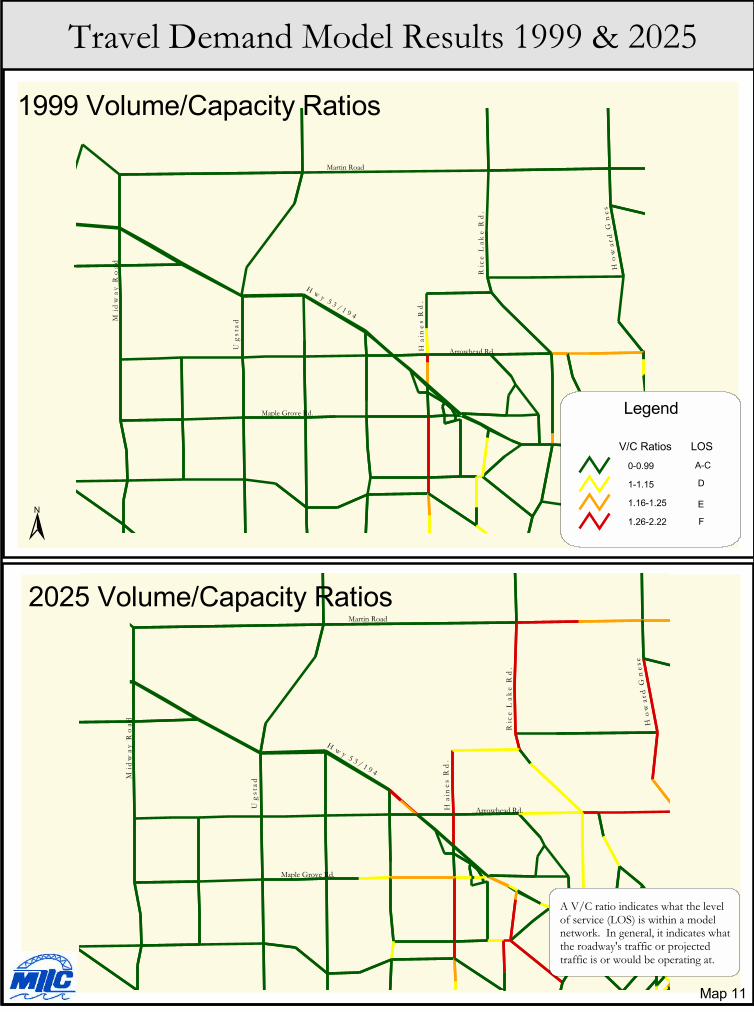
���
���
���
�
��
��
� � � � � � � � � �
���
����
���
������������
���
���
����
���
��
����
���
�
��� ����!�����
��� ������
������������ ������������
"��!� �#�$������� ����% �������&�'('�
���������������������������������������
����
��� ��
!"
#
$
���
���
���
�
��
��
� � � �� � � � � �
���
����
���
������������
���
���
����
���
��
����
���
��
��� ����!�����
��� ������������������ ������������
��)�*��� �������� ������ � ��� �!� +����!����,�-./������ ������$�� ��� ������0�������� 1�� ������� ������ � ���������2�� ��++�������3�� �� ��++���������% ��4������ ����� �
%� ���
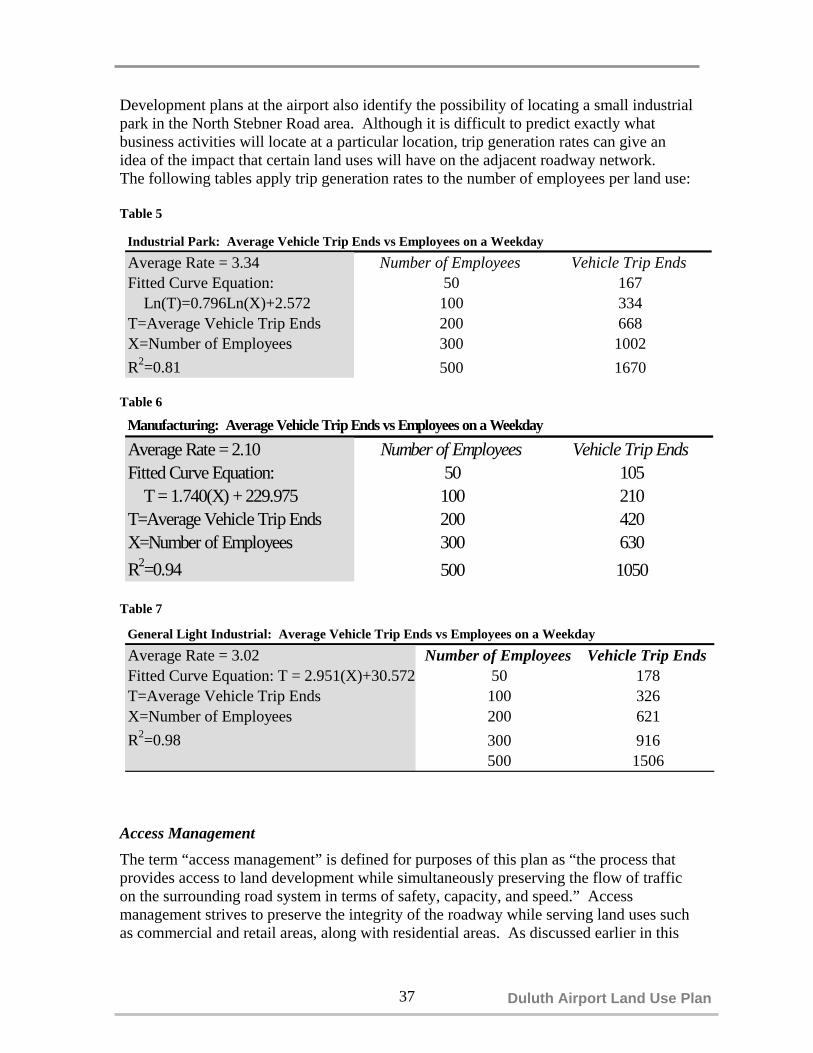
37 Duluth Airport Land Use Plan
General Light Industrial: Average Vehicle Trip Ends vs Employees on a Weekday
Average Rate = 3.02 Number of Employees Vehicle Trip EndsFitted Curve Equation: T = 2.951(X)+30.572 50 178T=Average Vehicle Trip Ends 100 326X=Number of Employees 200 621R2=0.98 300 916
500 1506
Development plans at the airport also identify the possibility of locating a small industrialpark in the North Stebner Road area. Although it is difficult to predict exactly whatbusiness activities will locate at a particular location, trip generation rates can give anidea of the impact that certain land uses will have on the adjacent roadway network. The following tables apply trip generation rates to the number of employees per land use:
Table 5
Table 6
Table 7
Access ManagementThe term “access management” is defined for purposes of this plan as “the process thatprovides access to land development while simultaneously preserving the flow of trafficon the surrounding road system in terms of safety, capacity, and speed.” Accessmanagement strives to preserve the integrity of the roadway while serving land uses suchas commercial and retail areas, along with residential areas. As discussed earlier in this
Industrial Park: Average Vehicle Trip Ends vs Employees on a Weekday
Average Rate = 3.34 Number of Employees Vehicle Trip EndsFitted Curve Equation: 50 167 Ln(T)=0.796Ln(X)+2.572 100 334T=Average Vehicle Trip Ends 200 668X=Number of Employees 300 1002R2=0.81 500 1670
Manufacturing: Average Vehicle Trip Ends vs Employees on a Weekday
Average Rate = 2.10 Number of Employees Vehicle Trip EndsFitted Curve Equation: 50 105 T = 1.740(X) + 229.975 100 210T=Average Vehicle Trip Ends 200 420X=Number of Employees 300 630R2=0.94 500 1050

39 Duluth Airport Land Use Plan
section, access to the airport is important for economic reasons. Also, accessmanagement is critical to maintaining connectivity to major highways from the airport.Preserving the integrity of roads in the airport area will maintain connectivity to thearea’s major highways. Access management on area highways and arterials is essentialbecause it can lead to improved safety, preservation of roadway capacity, and a reductionin the need for future system expansion.
Access management strategies for Trunk Highway 53 in the Duluth Airport area areoutlined in the Trunk Highway 53/194 Hermantown Access Management Plan completedin January 1999. This plan presents a number of ideas and techniques that would protectthe integrity of Trunk Highway 53 in the Duluth-Hermantown urbanized area. Furtheraccess management strategies will be outlined in the Miller Trunk HighwayImplementation Plan.
Future RoadsA number of planned improvements to the Duluth Airport facilities, along with futuregrowth of current airport area businesses and potential new developments, reveal a needfor new roadways (see Map 12) to provide access to these new developments. The needfor future road connections range from current needs to long term needs. A number ofplanning documents utilized for this study also identify the need for future roadways toaccommodate long-term future growth in the airport area. These documents includeDuluth International Airport Master Plan, the Minnesota Air National Guard MasterPlan Update, the Aviation Economic Development Plan, and the 1999 HermantownHighway 53/194 Access Management Plan.
A. New Airport Road Connection to Trunk Highway 53The current intersection of Airport Road with Highway 53/194 has limited sight distanceand insufficient space for cars waiting in the median crossover for traffic to clear. Carssitting in the median crossover also conflict with southbound traffic turning left onAirport Road. This intersection serves Cirrus, the Federal Prison Camp and the NaturalResources Research Institute (NRRI), along with a number of businesses and other landuses in this area.
Because the current location of the intersection would not accommodate a traffic signal,other locations were examined for a potential new intersection. One location identified inthe 1999 Hermantown Highway 53/194 Access Management Plan would move theintersection southeast to a point between Curtis Oil/Food & Fuel and NorthernHydraulics. A new access road would connect the new Airport Road with TH 53.
B. Relocation of Airport Road near CirrusThe lack of space to accommodate expansion plans at Cirrus has revealed a need torelocate the current alignment of Airport Road. Plans call for moving the road south andreconnecting either with the current Airport Road alignment or connecting with the newproposed connection to Trunk Highway 53. This alignment change would allow Cirrusto locate its expanded facility on the land that is now the current roadway.

40
C. MNANG Access Roads The MNANG base on the eastern side of the airport has two potential new roads plannedto accommodate future growth. Haines Road at its northern terminus currently serves asthe main entrance to the facility. Both short- and long-term plans call for a new mainentrance by relocating the Haines Road entrance to the east to divert vehicles entering thefacility away from the aircraft parking apron. Other short term plans at the MNANGinclude a number of internal circulation improvements. Long range plans include the development of a secondary access road and gate off of Ridgeview Road to provideaccess for fuel and munitions deliveries. Another long term option identified in theMNANG Master Plan Update calls for creating a new access road and main gate to theeastern edge of the MNANG facility and connecting with Airport Road to the east of theintersection of Haines and Airport Roads.
D. Future Air Cargo Area Access RoadAccording to the Duluth International Airport Master Plan, a new roadway will beneeded to serve the proposed cargo facility to be located south and east of Runway 3.This road would be an extension of Grinden Drive and possibly connect with AirbaseRoad or Swan Lake Road to the south to provide access to Trunk Highway 53.
E. North Development Area Aviation Expansion Connector In the north development area, long range plans call for a connection of North StebnerRoad with Lavaque Road. This new road would provide access to accommodate futureaviation related development. According to the North Area Conceptual Development
Map 12

41 Duluth Airport Land Use Plan
Plan in the Aviation Economic Development Plan, the new road connection along withnew taxiways would open a large area for aviation related development. The ASR Towerand the MNANG Munitions Maintenance Facility would have to be relocated prior todevelopment of this road. A new connection from North Stebner Road to Lavaque Roadwould also require upgrading to Lavaque Road to accommodate increased traffic.
Currently Programmed Roadway Improvement ProjectsThe following airport area roadway projects have been programmed and will becompleted in the next few years:
Airport Road/Airport Approach Road/Stebner Road LoopA recently completed gravel connection to Airport Approach Road has provided somerelief to the uncontrolled intersection at Trunk Highway 53 and Airport Road. This newgravel connection allows traffic to access Stebner Road, which has a signalizedintersection at Highway 53/194. This connected loop provides a connection from TrunkHighway 53 at Airport Road to Trunk Highway 53 at Stebner Road. This route alsoprovides access to Airbase Road and Arrowhead Road, which offers an alternate route fortraffic destined for East Duluth neighborhoods.
The recently completed gravel road connector will be upgraded to State-Aid standards in2002 or 2003. This federally funded project will also improve the connection withAirport Approach Road, reconfigure areas of Stebner Road and provide some intersectionimprovements at Stebner Road and Highway 53/194.
Trunk Highway 53/194 from Anderson Road to Midway RoadThis project is a mill and overlay of the driving lanes and shoulders. The project does notinclude any changes to roadway geometrics and is scheduled to take place in 2003.
Piedmont Avenue (Trunk Highway 53)The planned improvement of Piedmont Avenue section of Trunk Highway 53 in 2003-2004 will improve connectivity from the Duluth Airport to I-35. The new roadway willimprove traffic flow from I-35 to the Miller Hill Mall area. The project will split thecurrent Six Corners intersection into two separate intersections and move the TrunkHighway to the east of the present intersection. A new bridge will result in Skyline Drivepassing over the top of the highway. The total cost of this realignment and reconstructionproject will be $22 million.
SignageThe Institute of Transportation Engineers (ITE) developedguidelines for airport roadway signs entitled Airport RoadwayGuide Signs: A Proposed Recommended Practice, whichoffers the following: “Generally, there are one or two majorfeeder roads to an airport. All of the major roads whichintersect these feeders within a radius of 10-25 miles from theairport should carry the airport message as an integral part oftheir highway destination signs, including overhead signs.” Figure 4: Airport Trailblazer

42
Another suggestion is toplace a highway sign where major highways enter a community and then place“trailblazers” at all major intersections along the route to the airport. In the Duluth-Superior area the major roads which may need airport directional signage include I-35, I-535, TH 2, TH 53, and TH 61. A series of trailblazers (see Figure 4) would then directairport users to the intersection of TH 53 and Haines Road.
CONCLUSION
The analysis in this chapter highlights a number of areas of concern for the airport arearoadway network. A number of intersections and road segments should be improved ifdevelopment occurs in their vicinity. The following intersections and roadways segmentsare important to maintaining access and connectivity to the Duluth International Airportand should be closely monitored when airport area development plans are considered (seeMap 13).
A. Airport Road & Trunk Highway 53 – Sight distance and stacking problems exist atthe current intersection location. Short term plans include moving the intersection to thesoutheast on Trunk Highway 53 (see Future Roads). Given the potential expansion ofCirrus and the development of other businesses in the South Development Area, the newsignalized intersection would improve access and safety for these businesses. Thepresent intersection could be configured as a right-in/right-out with the median crossoverclosed. Development of the southern airport properties as well as on the southwest sideof Trunk Highway 53 may determine when any improvements may take place.
B. Airport Road/Airport Approach Road/Stebner Road Loop – This recentlyconnected roadway has relieved traffic pressure at the intersection of Airport Road andTrunk Highway 53 by providing an alternate route to Trunk Highway 53 via StebnerRoad. Construction to formalize this loop is scheduled for 2002 or 2003. This looproadway provides access for the South Development Area and the air cargo area currentlyoccupied by Federal Express. Future improvements to the road may include relocating asection of the roadway adjacent to Cirrus to provide them with expansion room. The newalignment is located where the access road would connect from the new Airport Roadintersection with Trunk Highway 53.
C. Stebner Road & Trunk Highway 53 – Development in the south area of the airportproperty along with the completion of the Airport Road loop from Trunk Highway 53near NRRI to Stebner Road will bring more traffic to this intersection. Signalimprovements and dedicated turn lanes for the north leg are scheduled for 2002 or 2003.
D. Haines Road & Trunk Highway 53 – This intersection is important to the AirparkIndustrial Park as well as the airport terminal area. This intersection will be examined aspart of the Miller Trunk Highway Implementation Plan. E. Trunk Highway 53 from Midway Road to I-35 – This segment of Trunk Highway
53 provides a connection from Duluth International Airport to I-35. The Miller Trunk
43 Duluth Airport Land Use Plan
Highway Implementation Plan will identify roadway design improvements such assignal coordination, land use/zoning strategies, and access management to protect theintegrity of this important segment of roadway.
F. Haines Road from Airport Road to Trunk Highway 53 – This segment of roadwayprovides a connection to Trunk Highway 53 for the airport terminal area as well asthe nearby Airpark Industrial Park. Future long-term improvements may includecapacity expansion.
G. Airport Road from Haines Road to Rice Lake Road – This segment is importantfor access to the airport terminal and Airpark Industrial Park as well as potential futureaccess for MNANG. Improvements to this road segment may include turn lanes andwider shoulders.
H. Rice Lake Road & Martin Road Intersection – Airport area development, alongwith increasing population and development in the townships north of Duluth, mayrequire upgrades to this intersection. Short term plans call for the extension of a sewerline along Rice Lake Road to Martin Road, which will promote growth in this area.Improvements to this intersection may include dedicated turn lanes and/or signalization.
I. Rice Lake Road & Airport Road – Increasing peak hour traffic is making accessonto Rice Lake Road difficult for vehicles eastbound on Airport Road. Futuredevelopment in this area may warrant traffic signals at this intersection.
J. Rice Lake Road from Arrowhead Road to Martin Road – Airport areadevelopment, along with increasing population and development in the townships northof Duluth, may require upgrades to this road segment. The planned sewer extensionalong this segment will also encourage development in this area. Possible improvementsto this segment include bypass lanes at intersections to accommodate left turning traffic.This improvement strategy could be extended farther north of Martin Road along RiceLake Road. Long term improvements may include additional travel lanes.
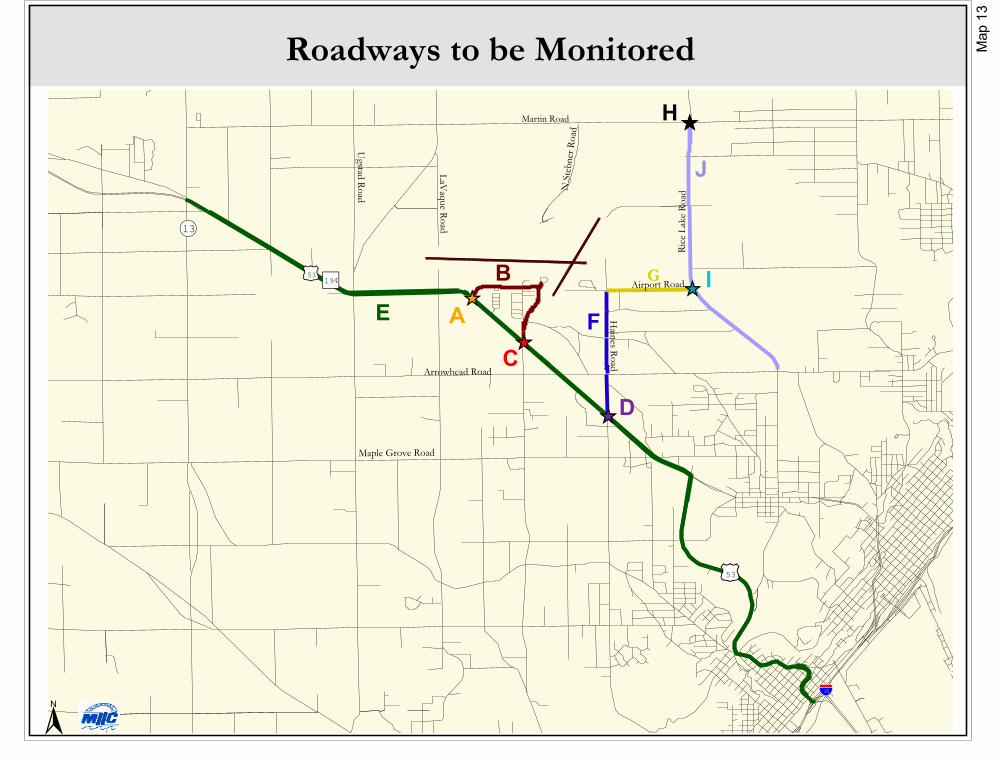
����
��
��
��
����
���������
���� �����
�����������
�����
�����
��
���������
���������
��������
�����
�������
���� �����
����
�������� ����
�����
��
�
�
�� �
�
�
����������� �������
�
�����
�

45 Duluth Airport Land Use Plan
CHAPTER 8: DEVELOPABLE LAND
A number of factors can influence what airport area land is most suitable fordevelopment. Wetlands, safety zones, airspace protection areas, aircraft noise impactareas, and the location of airport support equipment such as radar can have some bearingon where development occurs. Much of the geographic data collected for this studyillustrates the location of these factors. With the capabilities of Geographic InformationSystems (GIS), all of these factors can be analyzed together. This chapter attempts toillustrate the locations of the most developable land in the airport area and provide a moredetailed look at identified development areas.
Working with numerous data layers in a project can be challenging, especially when eachof those data layers can impact the final outcome of the analysis. In order to organize thedata and assess its relative importance in the final analysis, a ranking model is often used.A ranking model was developed for this project to better illustrate future developableareas.
Ranking involves placing attributes, such as wetlands and land use safety zones, intodiscrete classes. These classes are assigned numerical values based on their relativeimportance to developing airport parcels. This type of ranking, called the single additiveweighting model (SAW), involves a raw score that is added for all participatingattributes. This type of modeling has been used in numerous studies including a multi-attribute model developed by theKentucky Transportation Center toenhance the identification of routes.By assigning ranks to variousgeographic and economic featuresin the GIS database, theTransportation Center was able toprovide a single map that stemmedfrom all contributing attributesinvolved in the project.
Since the attributes used in thisstudy are discrete in nature,assigning a single score(representing developable vs. non-developable areas) to each attributewas sufficient. In this study, 16attributes were ranked according tothe below score (see Table 8).
100 = non-developable areas50 = some building restrictions0 = no building restrictions
Attribute Rank1500ft Radar Tower Buffer 1001/2 mile Radar Tower Buffer 90Munitions Maint. Facility 1250ft Buffer 100Land Use Zone A 100Land Use Zone B <3 acres 100 3-3.99 acres 50 4-5.99 acres 30 6-9.99 acres 20 >10 acres 10Land Use Zone C 0Parcels with buildings 100Runway visibility zone 100Runway safety area 100Runway protection zone 100Building restriction line 100Wetland areas 90Waste facilities 100Noise Contour 65db 20Noise Contour 70db 30Noise Contour 75db 40
Table 8: Attribute Inputs for SAW Model

46
The following section provides a brief explanation of the geographic input data for theSingle Additive Weight model.
Wetland Delineation A combination of 1:24,000 color infrared photography taken in September 1997 and1:2,400 monochrome photography taken in April 1995 were used to prepare updatedwetland maps. The intermediate scale color infrared photos provided importantinformation about vegetation types present in the wetlands, and the large scale springphotos allowed visualization of water and saturated soil beneath leafless woodyvegetation. The 1997 color infrared photos were digitally scanned, geo-referenced, andrectified to reduce distortion using a GIS warping routine that fits the scanned image toground coordinate control points obtained from a U.S. Geological Survey Digital OrthoQuad (DOQ). These digitally rectified aerial photos served as a geographically correctbase for identifying and delineating wetlands. Wetland classification followed U.S. Fishand Wildlife Service conventions for the National Wetlands Inventory (see Map 14).
No-Build/Electronic-Free BuffersCertain building restrictions exist within the North Development Area. The no-build andelectronic-free buffers represent a few of these restricted areas (see Map 5). No-buildbuffers, surround both the Airport Surveillance Radar (ASR) tower and the Air NationalGuard Munitions Maintenance Facility (MNANG MMF). The ASR tower has a 1500ftbuffer, while the MMF also has a 1250ft buffer. Furthermore, an electronic-free buffersurrounds the ASR radar tower and radiates out half a mile. The buffers were derivedusing the building boundaries, which were delineated using a Trimble Geoexplorer IIGPS.
BrownfieldsAnother concern surrounding development in the airport area is past and presentbrownfield sites. The Environmental Protection Agency defines brownfields as“abandoned, idled, or under-used industrial and commercial facilities where expansion orredevelopment is complicated by real or perceived environmental contamination.” Twomajor agencies, The Minnesota Air National Guard (MNANG) and the U.S. Air Force(USAF), were contacted to determine what brownfield sites exist at the airport. Twenty-eight sites in the study area were identified as areas of concern, or wheremitigation was completed or in process (see Map 19).
Noise ContoursThe noise contours used in this study were derived from the Noise Exposure Map createdfor the 1999 FAR Part 150 Study. These noise contours are based on a modeling processwhich utilized on-site noise measurements, runway and flight track geometry andutilization, approach and departure profiles, operational activity by type and time of day,and noise complaints from airport neighbors. The results of the model generated noisecontours for 1996 (existing conditions) and 2001 (future conditions). This study used the2001 contours, as did the Airport Overlay Zone Study of 1999 (see Map 7 ).

�������������� ������
�����������������������
������
�
�
��������������
����������� ������������������������������������������������������������������
��������������������������� ����������������������������
����
��� �!
"�����
#���$%
&'( & &'( $ # ��

49 Duluth Airport Land Use Plan
Parcel MapThis parcel layer (see Map 15) was created using current legal descriptions and digitizedparcel maps and was edited for topological and attribute errors using ArcInfo 8.Information was retrieved from the City of Duluth and St. Louis County Assessor'soffices. Data was attached using the parcel number. The Parcel map was completed inSeptember 2000 and has not been updated since then. Use constraints apply to this parceldata – please refer to the metadata associated with this geographic data.
Runway Restriction AreasFor the protection of people and property, the FAA has identified areas in close proximityto runways where buildings or structures of any kind are restricted (see Map 15). Theseareas include:
• Building Restriction Line - 300 feet on either side of the runway centerline. • Runway Protection Zone – a clear zone at the end of each runway. • Runway Safety Area – a defined area around runways that reduce risk of aircraft
accident. • Runway Visibility Zone – a defined area near the intersections of runways that allows
pilots to see other runways.
Land Use Safety ZonesAs described in Chapter 3, Land Use Safety Zones A, B, & C were created to protectaircraft operational safety and the general public’s life and property. Specific land userestrictions are associated with each zone, with Safety Zone A being the most and SafetyZone C the least restrictive.
Each of these attributes is spatially related to a data layer in the GIS system. GIS SpatialAnalyst capabilities allowed the data layers to be individually ranked and overlaid toproduce a single data layer. This single layer represents the overall potential fordevelopment in the study area based on the 16 attributes. The results of the developmentranking are shown in Map 16. The darker colors represent the most suitable areas fordevelopment. The lighter colors represent areas least suitable for development.
The results of the SAW model show large areas of developable land north and south ofthe airport. Of the area south of the airport, a large portion lies south and west of trunkHighway 53 in Hermantown and was not the focus of this study. The other portion southand east of the airport falls near the Airpark Industrial Park and is currently developed orbeing developed. The small area directly south of and adjacent to Runway 9-27 iscurrently being redeveloped. This area is the location of Cirrus Designs and the FederalPrison Camp. A large portion of the area to the north of the airport is identified asdevelopable and falls within an area identified for future development.
According to the Aviation Economic Development Plan of January 1998, the DuluthAirport Authority has targeted two primary areas for future development (see Map 17).Located in the South Redevelopment Area are unused buildings from the former AirForce Base, as well as a number of industrial- and office-use buildings. Since utilities

50
currently exist in this area it is for the most part ready for short-term development. TheNorth Development Area is located along North Stebner Road and is where NorthwestAirlines Maintenance Facility is sited. The location along North Stebner Road is targetedfor business park development and the area adjacent to and west of the Northwest facilityis targeted for aviation-related development. A more detailed examination ofdevelopable land was conducted for the North Development Area.
North Development AreaAs described above, this area is a prime site for new industrial and business developmentdue to the recent addition of North Stebner Road and the extension of utilities to theNorthwest Airlines Maintenance Facility. However, wetlands and poor soils predominatein this area (Airport Master Plan). Additional concerns in this area include utility costs,the ASR no-build buffer, the electronic-free buffer and the MNANG MunitionsMaintenance Facility no-build buffer, aswell as brownfield sites.
Certain building restrictions exist withinthe North Development Area. The no-build and electronic-free buffersrepresent a few of these restricted areas(Map 18). No-build buffers, which arefound in the Duluth InternationalAirport Master Plan, surround both theASR radar tower and the MNANGMMF. The ASR tower has a 1500ftbuffer, while the MMF also has a 1250ftbuffer. Furthermore, an electronic-freebuffer surrounds the ASR radar towerand radiates out one-half mile.
Another concern surrounding theNorthwest Development Area is the presence of old and current brownfield sites. TheEnvironmental Protection Agency defines brownfields as “abandoned, idled, or under-used industrial and commercial facilities where expansion or redevelopment iscomplicated by real or perceived environmental contamination.” Two major agencies,The Minnesota Air National Guard (MNANG) and the U.S. Air Force (USAF), werecontacted to determine the location and contents of known brownfield sites at the airport.Twenty-eight sites in the study area were identified as areas of concern, or wheremitigation was either completed or in process.
The U.S. Air Force is in the process of cleaning a plume of trichloryll ethylene (TCE)contamination that originated from the primary landfill site. The source of thecontamination has been removed and remediation is under way (Aviation EconomicDevelopment Plan).
Map 18

������������
�����
������
���
��������
��������� ����������
���������
��� �
�!�����
�
"��#�����
$� ������
"�������������� ����
"��!������
����%������
"��#����� ��%��
�& �����'(�����
���������
�
"��#��������������� ����������������"����
�������
���
��� ���������� �����
��� ������ �����
��� ����������������
������ �������
�����������������������
����
������
) * ) �����
�����

������������������� ������������������������������������ �� ���������� ������������� �������� ������� ���������� �������� ������ �����
�������������������������� ������ ������������������ ���������� ������������������� � �������� ���������������� � ���!!������� ����� �����
�
����������� ������������ �����
������ �����
������ ���������������������
� � � �����
"��� ������#��� ������

����� �����
�����
�������
�����
���������
��������
���������
��������������
������
�
���� �����
����� ����
!��������
�
������������� ������
������������� ������
��������������� ������
����� ��
�� ���
�����
���� �
" # " $ !�%��
������

56
The remaining sites in theNorth Development Area
are closed or tagged asareas of concern (see Map
19).
A detailed wetlanddelineation of theNorthwest Developmentarea is vital to determineand analyze the futuredevelopment options of theDuluth InternationalAirport (see Map 20). TheAirport Master Planclearly states that “toaccurately determine theproposed on and off airportimpacts and mitigationrequirements, a detailed field survey is required.”
The North Development Area as defined in the Aviation Economic Development Plan isapproximately 962 acres. Over one third of this area has been delineated as wetlands.Due to this large percentage of wetlands, mitigation strategies will have to accompanyany future development plans. Mitigation is a system for balancing wetland lossesagainst wetland gains, under Section 404 of the Clean Water Act. Under this act, landowners needing to “mitigate,” or compensate for authorized impacts to wetlandsassociated with development activities, have the option of in-kind mitigation ormitigation banking approaches. In-kind mitigation refers to replacement of a specificwetland type with the same wetland type in another area. Mitigation banking is when awetland area that has been restored, created, or enhanced is set aside to compensate forfuture conversions of wetlands for development activities. Banking can provide morecost effective mitigation and reduce uncertainty and delays for qualified projects.Furthermore, banking saves time in permit processing due to the ability to pre-select amitigation site. Once the quantity of impacted wetlands is known, mitigation strategiesmay then be formulated.
A further breakdown of the wetlands shows the specific wetland classes which may aid indeveloping mitigation strategies. These wetland classes were derived from the NationalWetlands Inventory.
If development were to occur in the North Development Area, utility service would needto be extended. At present, the City of Duluth Water and Gas extended a 10” water mainand 10” HP gas main to the Northwest Airlines Maintenance Facility. Both utilitysystems are looped systems and have increased the capacity for service in the proposeddevelopment areas. In addition, both utility services are capable of expanding services.
Map 19

57 Duluth Airport Land Use Plan
The sanitary sewer system, maintained by the City of Duluth, is adequate to handle futureexpansion. A new sanitary sewer consisting of a force main, a gravity main, and asewage lift station has been constructed for the Northwest Airlines Maintenance Facility.This system has capacity for future development in the North Development Area(Aviation Economic Development Plan).
Water, sewer, and gas line extensions were examined to determine rough cost estimates.(see Maps 21 & 22). Since the most likely extensions to these lines will occur at theNorthwest Maintenance Facility, 1000ft buffers were placed around the lines closest toNorthwest. A series of buffers were completed to encompass the parcels in the NorthDevelopment Area. Cost information was obtained from the city for extending theseutilities and used in conjunction with the buffers to determine general cost estimates ofextending the utility lines.
The City of Duluth listed an average cost of $70/foot for either water or sewer extensionswith average depth and minimal pavement repair. The cost increases to $85/foot if morepavement was encountered and to $100-125/foot if rock was encountered. Gas lineextensions were not included in this analysis because costs may vary for installationdepending on the projected volume of gas to be used. A high volume gas customerwould most likely have a line extended to their site free of charge. By examining theinformation on Maps 21 and 22, we can see that developing the parcels nearest toNorthwest may be the most cost effective to develop in the short term.
The North Development Area provides opportunities for industrial, manufacturing, andbusiness park development. Parcels exist that are relatively free from wetlands and havegood roadway access. However utility extensions would be needed. Given the long-termplans for this area, short-term development is suitable for this area.
Airport DevelopmentThe Duluth Airport is limited by Federal statues in the level of economic developmentactivity in which it can participate. There are two key areas the Duluth Airport Authorityis responsible for in economic development. One is to continually improve the aviationsupport infrastructure such as runways, instrument approaches, the airport terminal,aircraft parking areas etc. The other is to provide airport land for aviation relateddevelopment. This then allows the private or governmental sector to market Duluth andthe Duluth International Airport with the best possible advantages.
In order for the Duluth Airport Authority to continually upgrade facilities andinfrastructure, it must continually and aggressively pursue federal funding from theAirport Improvement Program funds. The Airport Improvement Program results in allmajor projects receiving 90% federal funding with the remaining 10% cost coming fromlocal airport funds. The local funds are generated by the airport through parking lotrevenue, land leases, passenger services, rental car operation, landing fees etc. Without

�
������������� ���������������
��������
��� ���������
������������� ����������� ��
������������ ���� �������������� ������
��
��
��
���
����������� ��������������������������������������������������������������������������������������
������� ����������������������������
�������� ������������
������!������"�# ��
���������$� ��%���� � �"
&��'�"
#�����
$���()

������������������� �� ��������������������� ���������������������� ������������� ������ �� ��������������������������������������������������� ������ �� ����������������������������������� ���������������������� �� �� ���
���������� ������������������������ �������������������������� �������������� �� ������ ������������������� ����
� �������������� ����!����� ���"������ ��#���$�������������������������������������������#����$
�������������%&�����������%'(��������%������������)�����������%�*���������%�&�������%)�����������+�����������%)����������%)((������%+�����������*�����������%)'���������%+*�������%*�����������(�����������%+(���������%*)(������%(�����������,�����������%*)���������%(��������%,�����������&�����������%*-���������%(-(������%&�����������'�����������%(,���������%,'�������%'����������
� � � �����
�
������ ��������� ���������� �������
������������������ ��������������
����
����
����
����
.����/���� � ����01� ����� �
���!
�
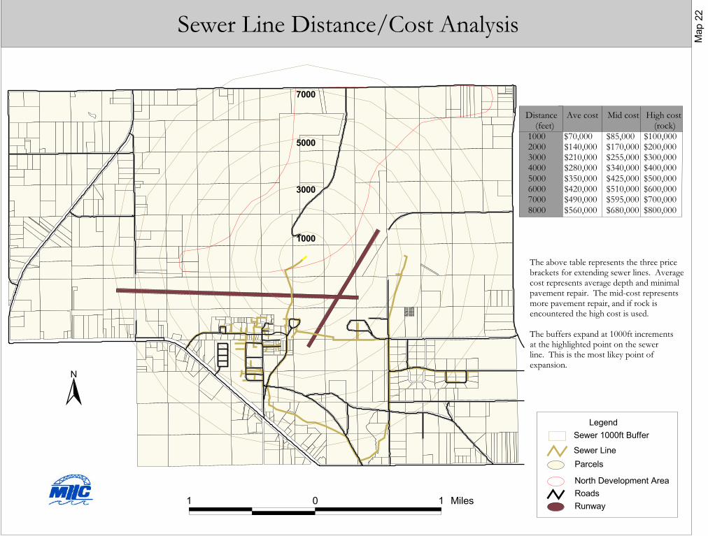
�������������� ��������������������������
������������������������������������������������������ �������������������� ������������������� ������������������� ����������������������!��������������������!������������"�������"�������������������!������!��������������
� � � �����
�
������ ��������� ���������� �������
������
����������������������� �����
����
����
����
����
#���$�����$%���&���������������&����$�����������'���������(��%����)������������&����������������&�����*���*�%&���*�����&���)#��*��+������&�������*���&���*�����&�������������������,�������������������,���)
#��$,������'&����������������*�������������%������&�����������(��%���)#��������*���%���-&�������'&������)
.�(��/�����������01�����%-���
�� �!!

61 Duluth Airport Land Use Plan
the 10% local match, the federal government will not provide the 90% share of anyproject costs. Therefore it is critical that the airport maintains a lease rate structure over
the long period of time that allows the necessary reserve of local funds to continuallyapply for and receive the federal grants.
Local government and private development entities in dealing with airport property andairport development must understand this concept. Any financial economic stimuli suchas reduced lease rates, long-term leases not increased by economic indexes, or directmonetary contributions reduce the availability of federal funds due to the inability of theairport to generate the necessary 10% local share. The Federal Airport ImprovementProgram presents the opportunity to leverage a 9-to-1 share for airport improvementdollars.

62
CHAPTER 9: CONCLUSION
The general public has a significant stake in protecting the viability of the DuluthInternational Airport. Access to world-wide air travel along with a significant number ofjobs provide incentive from the public’s perspective to preserve the airport and its relatedfunctions. A regional approach that considers the needs of all communities involved isnecessary to produce a strategy of compatible land uses that everyone can live with.
The Duluth International Airport currently has economic advantages that can lead to thegeneration of high paying jobs in the aviation industry. The 10,000 ft. main runway canhandle the world’s largest aircraft. Lower levels of air traffic create a desirable locationfor aviation related businesses. The current operations of Cirrus Designs and theNorthwest Airlines Maintenance Facilities provide this region with a solid base ofaviation businesses. Building upon this strength is an approach that many economicdevelopment policies are attempting to take advantage of.
Land use can be a potentially controversial issue when jurisdictions are being told whatthey can and can’t do with their land. However, given the economic importance of theDuluth airport to this region and the cost that other airports have incurred to solve landuse compatibility issues, all area jurisdictions should make every attempt to preventincompatible land use in the airport vicinity. A particular goal of this study is toencourage compatible land uses in the airport area in order to protect the community, itstaxpayers, and the economic viability of the area, while minimizing any burden to airportarea property owners.
One step that local jurisdictions can undertake to ensure that land uses are compatiblewith aircraft noise is to adopt the Airport Overlay Zone Study that was created for theDuluth International Airport. Of the four jurisdictions bordering the airport, Rice Lakeand Canosia Townships have adopted the study. To date, the cities of Duluth andHermantown have not adopted the study. The strategies listed in the study are anexample of best practices for noise compatible land uses in airport areas and are currentlyin place in a number of locations throughout the country. These strategies are designed toprotect a significant public investment. Local comprehensive plans and zoning ordinances for those communities located near theairport should be reviewed, and, if necessary, amended to incorporate recommendationsaddressing compatible land uses and developments. In areas adjacent to the airport, landuses should be compatible with the role and function of the airport while maintainingexisting compatible community uses.
Growth Risk AreasAnalysis of the data collected for this study illustrate that some areas may be moredifficult to develop airport compatible land uses. Development pressures can steerincompatible uses toward areas that may not be suitable. These areas are sometimesreferred to as “growth risk areas.” Identification of these areas can be helpful to assist inmonitoring development proposals that may need review of airport noise and safety

63 Duluth Airport Land Use Plan
compatibility issues. Factors considered in developing the growth risk areas include thelocation of noise impacted areas, airport safety zones, future airport expansion plans, andthe Duluth Airport Zoning Ordinance. The areas shown on Map 23 encompass the noisecontours from 60 DNL and above along with all areas that fall in Safety Zones A, B, &C. These areas are the most susceptible to airport related impacts and should bemonitored to ensure development of airport compatible uses.
Martin Road
Ugstad Rd
Lavaque Rd
N Ste
bner
Rd
TH 53 Airport Rd
Arrowhead Rd
Haines R
d
Rice Lake R
dGrowth Risk Area
Map 23