DTA10-105 IHD ROTARY ACTUATOR DEVELOPEMENT
8
DTA10-105 IHD ROTARY ACTUATOR DEVELOPEMENT Iker Sainz (1) , Aitor Isturiz (1) , Ander Pereda (1) , Pablo Riera (1) , Jon Peña (1) (1) SENER, Av. Zugazarte 56, 48930 Las Arenas (Bizkaia) Spain, Email: [email protected] [email protected]; [email protected]; [email protected]; [email protected] ABSTRACT The rotary actuator DTA10-105 Integrated Harmonic Drive ®(IHD) is the result of the long self-funded development of the High Detent Torque Rotary Actuator (DTA) family from SENER Aeroespacial. The DTA10-105 IHD rotary actuator provides remarkable differences with respect to the existing industry standard for medium size (~ø100mm/ 4 inches) rotary actuators. The most outstanding/key features are the great torsional stiffness and the huge torque (both powered and unpowered) capabilities. These remarkable differences will allow the DTA10-105 IHD actuator to provide a disruptive change in the actual existing rotary actuators market, especially for those applications in which the pointing accuracy is critical (such as antenna pointing mechanisms). This rotary actuator is a fully European technology and therefore has no ITAR/EAR regulation restrictions. The paper describes all design phase studies, analysis and the tests results showing the most relevant performances of this novel actuator. 1. BACKGROUND & HERITAGE SENER Aeroespacial has been working in the development of tailored rotary Actuators for the last decade, having already successful flight heritage in various applications. As a result, the DTA family rotary actuators are now available from sizes ~ø40 (DTA4) to sizes ~ø100 (DTA10). Figure 1.1 DTA10-105 IHD rotary actuator Additionally, for the last 5 years SENER Aeroespacial has increased its capabilities with the design and manufacturing of its own stepper motors (SUM family). During this time frame, the DTA product family actuators for the telecommunication market (DTA10- 103, former DTA-1201) were qualified and industrialized for series production. More than 200 units have been contracted, of which over 70 flight units have already been delivered to the client. Figure 1.2 DTA family rotary actuators: DTA6-200 (left), DTA10-105 IHD (center) and DTA4-302 (right) According to the industry needs, the main product so far has been the medium size actuator (Ø120mm/4.7 inch and ~2kg/4.4 pounds) with Harmonic Drive® reducer so called DTA (Detent Torque Actuator). There are several suppliers all over the world manufacturing these medium-size actuators, including the Harmonic Drive® HFUC/CPL Gear size 20. Within the development of the DTA family actuators, SENER Aeroespacial has identified a recurrent request on the market of rotary actuators in this medium size for increased torsional stiffness and unpowered holding torque, while keeping the size/mass/performances of the rotary actuator. The torsional stiffness is mainly defined by the reduction gear, whereas the unpowered holding torque is driven by the motor and the gear ratio. This technology limitation within the reduction gear was the core at the beginning of the development. The existing architecture (using standard Harmonic Drive®) gears does not allow the improvement of this characteristic with reliable series results.
Transcript of DTA10-105 IHD ROTARY ACTUATOR DEVELOPEMENT

DTA10-105 IHD ROTARY ACTUATOR DEVELOPEMENT
Iker Sainz (1), Aitor Isturiz (1), Ander Pereda (1), Pablo Riera (1), Jon Peña (1)
(1) SENER, Av. Zugazarte 56, 48930 Las Arenas (Bizkaia) Spain, Email: [email protected]
[email protected]; [email protected]; [email protected];
ABSTRACT
The rotary actuator DTA10-105 Integrated Harmonic
Drive ®(IHD) is the result of the long self-funded
development of the High Detent Torque Rotary Actuator
(DTA) family from SENER Aeroespacial.
The DTA10-105 IHD rotary actuator provides
remarkable differences with respect to the existing
industry standard for medium size (~ø100mm/ 4 inches)
rotary actuators. The most outstanding/key features are
the great torsional stiffness and the huge torque (both
powered and unpowered) capabilities.
These remarkable differences will allow the DTA10-105
IHD actuator to provide a disruptive change in the actual
existing rotary actuators market, especially for those
applications in which the pointing accuracy is critical
(such as antenna pointing mechanisms).
This rotary actuator is a fully European technology and
therefore has no ITAR/EAR regulation restrictions.
The paper describes all design phase studies, analysis and
the tests results showing the most relevant performances
of this novel actuator.
1. BACKGROUND & HERITAGE
SENER Aeroespacial has been working in the
development of tailored rotary Actuators for the last
decade, having already successful flight heritage in
various applications. As a result, the DTA family rotary
actuators are now available from sizes ~ø40 (DTA4) to
sizes ~ø100 (DTA10).
Figure 1.1 DTA10-105 IHD rotary actuator
Additionally, for the last 5 years SENER Aeroespacial
has increased its capabilities with the design and
manufacturing of its own stepper motors (SUM family).
During this time frame, the DTA product family
actuators for the telecommunication market (DTA10-
103, former DTA-1201) were qualified and
industrialized for series production. More than 200 units
have been contracted, of which over 70 flight units have
already been delivered to the client.
Figure 1.2 DTA family rotary actuators: DTA6-200
(left), DTA10-105 IHD (center) and DTA4-302 (right)
According to the industry needs, the main product so far
has been the medium size actuator (Ø120mm/4.7 inch
and ~2kg/4.4 pounds) with Harmonic Drive® reducer so
called DTA (Detent Torque Actuator). There are several
suppliers all over the world manufacturing these
medium-size actuators, including the Harmonic Drive®
HFUC/CPL Gear size 20. Within the development of the
DTA family actuators, SENER Aeroespacial has
identified a recurrent request on the market of rotary
actuators in this medium size for increased torsional
stiffness and unpowered holding torque, while keeping
the size/mass/performances of the rotary actuator. The
torsional stiffness is mainly defined by the reduction
gear, whereas the unpowered holding torque is driven by
the motor and the gear ratio.
This technology limitation within the reduction gear was
the core at the beginning of the development. The
existing architecture (using standard Harmonic Drive®)
gears does not allow the improvement of this
characteristic with reliable series results.
2. DESIGN EVOLUTION DESCRIPTION
Harmonic Drive AG and SENER Aeroespacial have long
experience working together in the domain of space
qualified rotary actuators.
The typical approach has always been based on customer
specification that leads SENER Aeroespacial to develop
a new mission related/tailored product. Suppliers provide
the existing hardware and the complete architecture is
based on this.
In this case, SENER Aeroespacial involved engineers
from Harmonic Drive right at the beginning of the
development to jointly identify which application needs
could be solved easier by a new design of the gear.
Looking to the aviation industry, designs are usually
integrated for reasons of form-fit rather than screw
connections, but also for better and more efficient
assembly processes that are necessary at higher volumes.
One key aspect when integrating customer housing of a
mechanism and the part with the biggest diameter of the
gear (Circular Spline) into a single piece solution is that
the overall mechanism structure can be designed to
provide high radial stiffness to support the best
functionality of the gear.
Moreover, this allows improving the torsional stiffness,
load capabilities, reduction ratios, etc. per design as
bigger sized gearing can be integrated in the same outer
design (rotary actuator) envelope. The torsional stiffness
of the Harmonic Drive® Gear itself will remain nearly
the same, but it is possible to use a gear one size bigger
in the same outer diameter, which increases the resulting
performances significantly.
Figure 2.1 Integrated Harmonic Drive® design
This required also to adapt the angular contact bearings
(both at motor and outer level) to the new shape of the
Integrated Harmonic Drive design. Additionally,
SENER Aeroespacial has designed a specific tailored
motor, the SUM69-360 mark II.
3. DTA10-105 IHD DESIGN DESCRIPTION
The actuator’s novelty is based on:
- Tailored outbreaking stepper motor for this specific
design, the SUM 69-360 mark II.
- Tailored design of Harmonic Drive® based on a
long-time co-working between both companies in
the domain of space-qualified rotary actuators.
- The bearings have also been optimized specifically
for this design.
- It also includes two fine & coarse redundant
potentiometers.
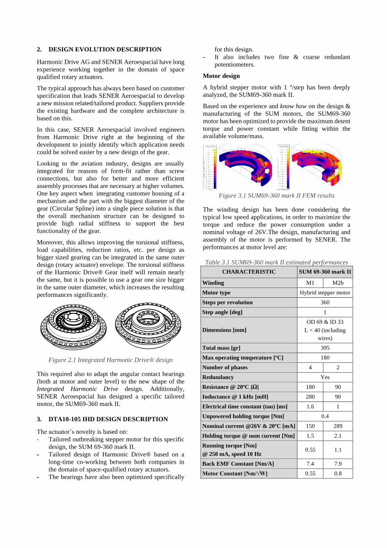
Motor design
A hybrid stepper motor with 1 º/step has been deeply
analyzed, the SUM69-360 mark II.
Based on the experience and know how on the design &
manufacturing of the SUM motors, the SUM69-360
motor has been optimized to provide the maximum detent
torque and power constant while fitting within the
available volume/mass.
Figure 3.1 SUM69-360 mark II FEM results
The winding design has been done considering the
typical low speed applications, in order to maximize the
torque and reduce the power consumption under a
nominal voltage of 26V.The design, manufacturing and
assembly of the motor is performed by SENER. The
performances at motor level are:
Table 3.1 SUM69-360 mark II estimated performances
CHARACTERISTIC SUM 69-360 mark II
Winding M1 M2b
Motor type Hybrid stepper motor
Steps per revolution 360
Step angle [deg] 1
Dimensions [mm]
OD 69 & ID 33
L < 40 (including
wires)
Total mass [gr] 395
Max operating temperature [ºC] 180
Number of phases 4 2
Redundancy Yes
Resistance @ 20ºC [Ω] 180 90
Inductance @ 1 kHz [mH] 280 90
Electrical time constant (tau) [ms] 1.6 1
Unpowered holding torque [Nm] 0.4
Nominal current @26V & 20ºC [mA] 150 289
Holding torque @ nom current [Nm] 1.5 2.1
Running torque [Nm]
@ 250 mA, speed 10 Hz 0.55 1.1
Back EMF Constant [Nm/A] 7.4 7.9
Motor Constant [Nm/√W] 0.55 0.8

Figure 3.2 SUM69-360 mark II M1 & M2b torque vs
current
Note: All performances are considering 1 single phase ON full stepping
command at 10 Hz command speed.
Tailored Kt/resistances values can be easily done by
simply modifying the winding parameters. The reference
value of the power constant remains the same (or could
be decreased, but never increased) for all the different
requested windings.
Gear design
As stated above, the gear design has been done in order
to fit the CPL size 25 within the same volume of the
rotary actuators using CPL size 20.
The result is a massive fixed tailored CS (circular spline)
design which provides mechanical interface for the motor
on one side and output bearing on the other side. With
this new rotary actuator architecture, the CPL size 25 fits
within the DTA10 family (~ø100 mm) rotary actuators.
Besides, removing the typical bolt/screw interface allows
an additional improvement of the transmission accuracy.
Additionally, the bigger size allows the possibility to
increase the gear ratio up to 200:1. However it was
decided to build the prototype with the standard gear ratio
of 160.
The gear has been deeply analyzed with a dedicated FEM
by Harmonic Drive® AG in order to design and optimize
the IHD. All results have been compared to the standard
CPL size 20, as it was the target gear to be superseded.
Figure 3.3 IHD Torsion stiffness FEM evaluation
The analysis has shown in every component (Circular
Spline, Flexible Spline and Wave Generator) significant
stress margin with respect to the size 20 standard gear
when the output torque is above 20 Nm, which is the
typical specification/qualification load for DTA10
actuators.
Regarding the lifetime, the peak contact stress (lower),
the percentage teeth in contact (lower share = beneficial)
and the toothing contact stress (lower) show that the
design of the IHD withstands better than the CPL size 20
the 20 Nm output load. Therefore, it can be concluded
that the lifetime performance is even greater than the
heritage showed in [1].
Tab. 3.2 summarizes the design conclusions:
Table 3.2 IHD CPL-25 performances vs CPL-20
Figure 3.4 IHD Torsion stiffness test result
Finally, Tab. 3.3 summarizes the most critical
performances test results:
Table 3.3 IHD test result
CHARACTERISTIC IHD tested value
Transmission accuracy [arcsec] < 20
Torsion stiffness [Nm/mrad]
K1 (up to 7.5Nm)
K2 (7.5 to 25 Nm)
K3 (25 to 40 Nm)
37.5
35.5
42.6
Mass [gr] 900
As it is observed, the key characteristic (torsion stiffness)
target has been accomplished.
Bearings design
The bearings were redesigned to fit in the new available
volume: from a specific integrated bearing system
providing both input (motor) and output (actuator’s
output) bearing to two regular independent angular
contact bearings.
For this new design, the preload and the stiffness & load
capabilities of both bearings were optimized with a
specific bearing calculation tool. These results were later
correlated with the performance data provided by the
bearing supplier (Barden):
Figure 3.5 Output bearing nominal preload stress
In a previous model [1] under maximum loads (random
vibration) minimal gapping could be induced within the
bearing. Considering the increased motor torque
characteristics and the negligible friction influence on
them, both bearings nominal preload was increased.
Following supplier recommendations, the nominal
preload was increased leaving a margin according to the
typical fatigue limit of the bearings (about 2000 MPa).
Tab. 3.4 summarizes the bearings performances:
Table 3.4 DTA10-105 IHD bearings performances
CHARACTERISTIC Output bearing Motor bearing
Type Back to Back (O) arrangement
Hard preloaded angular contact
Size [mm] OD ~89 ID ~71
L ~18
OD ~45 ID ~33
L ~10
Nominal preload [N]
& stress [MPa]
2300
1730
270
1500
Stiffness
Axial [N/um]
Radial [N/um]
Bending [Nm/mrad]
430
580
450
120
200
35
Load limits @ 3700 MPa
Axial [kN]
Radial [kN]
Bending [Nm]
30
21.5
450
5
3.9
50
With these performances, bearing specifications were
sent to the supplier and the bearings were correctly
manufactured.
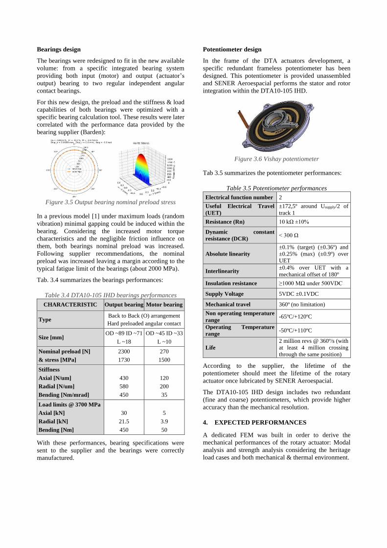
Potentiometer design
In the frame of the DTA actuators development, a
specific redundant frameless potentiometer has been
designed. This potentiometer is provided unassembled
and SENER Aeroespacial performs the stator and rotor
integration within the DTA10-105 IHD.
Figure 3.6 Vishay potentiometer
Tab 3.5 summarizes the potentiometer performances:
Table 3.5 Potentiometer performances
Electrical function number 2
Useful Electrical Travel
(UET)
±172,5º around Usupply/2 of
track 1
Resistance (Rn) 10 kΩ ±10%
Dynamic constant
resistance (DCR) < 300 Ω
Absolute linearity
±0.1% (target) (±0.36º) and
±0.25% (max) (±0.9º) over
UET
Interlinearity ±0.4% over UET with a
mechanical offset of 180º
Insulation resistance ≥1000 MΩ under 500VDC
Supply Voltage 5VDC ±0.1VDC
Mechanical travel 360º (no limitation)
Non operating temperature
range -65ºC/+120ºC
Operating Temperature
range -50ºC/+110ºC
Life
2 million revs @ 360º/s (with
at least 4 million crossing
through the same position)
According to the supplier, the lifetime of the
potentiometer should meet the lifetime of the rotary
actuator once lubricated by SENER Aeroespacial.
The DTA10-105 IHD design includes two redundant
(fine and coarse) potentiometers, which provide higher
accuracy than the mechanical resolution.
4. EXPECTED PERFORMANCES
A dedicated FEM was built in order to derive the
mechanical performances of the rotary actuator: Modal
analysis and strength analysis considering the heritage
load cases and both mechanical & thermal environment.
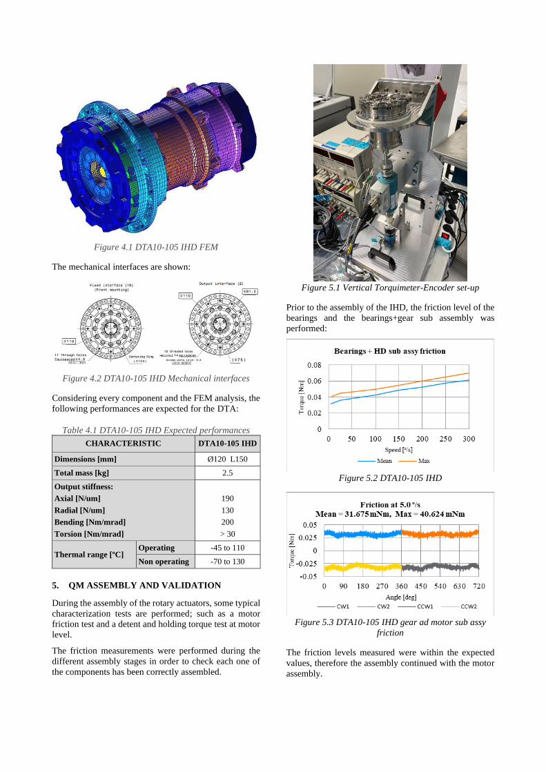
Figure 4.1 DTA10-105 IHD FEM
The mechanical interfaces are shown:
Figure 4.2 DTA10-105 IHD Mechanical interfaces
Considering every component and the FEM analysis, the
following performances are expected for the DTA:
Table 4.1 DTA10-105 IHD Expected performances
CHARACTERISTIC DTA10-105 IHD
Dimensions [mm] Ø120 L150
Total mass [kg] 2.5
Output stiffness:
Axial [N/um]
Radial [N/um]
Bending [Nm/mrad]
Torsion [Nm/mrad]
190
130
200
> 30
Thermal range [ºC] Operating -45 to 110
Non operating -70 to 130
5. QM ASSEMBLY AND VALIDATION
During the assembly of the rotary actuators, some typical
characterization tests are performed; such as a motor
friction test and a detent and holding torque test at motor
level.
The friction measurements were performed during the
different assembly stages in order to check each one of
the components has been correctly assembled.
Figure 5.1 Vertical Torquimeter-Encoder set-up
Prior to the assembly of the IHD, the friction level of the
bearings and the bearings+gear sub assembly was
performed:
Figure 5.2 DTA10-105 IHD
Figure 5.3 DTA10-105 IHD gear ad motor sub assy
friction
The friction levels measured were within the expected
values, therefore the assembly continued with the motor
assembly.
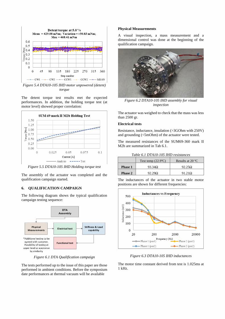
Figure 5.4 DTA10-105 IHD motor unpowered (detent)
torque
The detent torque test results met the expected
performances. In addition, the holding torque test (at
motor level) showed proper correlation:
Figure 5.5 DTA10-105 IHD Holding torque test
The assembly of the actuator was completed and the
qualification campaign started.
6. QUALIFICATION CAMPAIGN
The following diagram shows the typical qualification
campaign testing sequence:
Figure 6.1 DTA Qualification campaign
The tests performed up to the issue of this paper are those
performed in ambient conditions. Before the symposium
date performances at thermal vacuum will be available
Physical Measurements
A visual inspection, a mass measurement and a
dimensional control was done at the beginning of the
qualification campaign.
Figure 6.2 DTA10-105 IHD assembly for visual
inspection
The actuator was weighed to check that the mass was less
than 2500 gr.
Electrical tests
Resistance, inductance, insulation (>3GOhm with 250V)
and grounding (<5mOhm) of the actuator were tested.
The measured resistances of the SUM69-360 mark II
M2b are summarized in Tab 6.1.
Table 6.1 DTA10-105 IHD resistances
Test temp (22.9ºC) Results at 20 ºC
Phase 1 93.34Ω 92.25Ω
Phase 2 92.29Ω 91.21Ω
The inductances of the actuator in two stable motor
positions are shown for different frequencies:
Figure 6.3 DTA10-105 IHD inductances
The motor time constant derived from test is 1.025ms at
1 kHz.
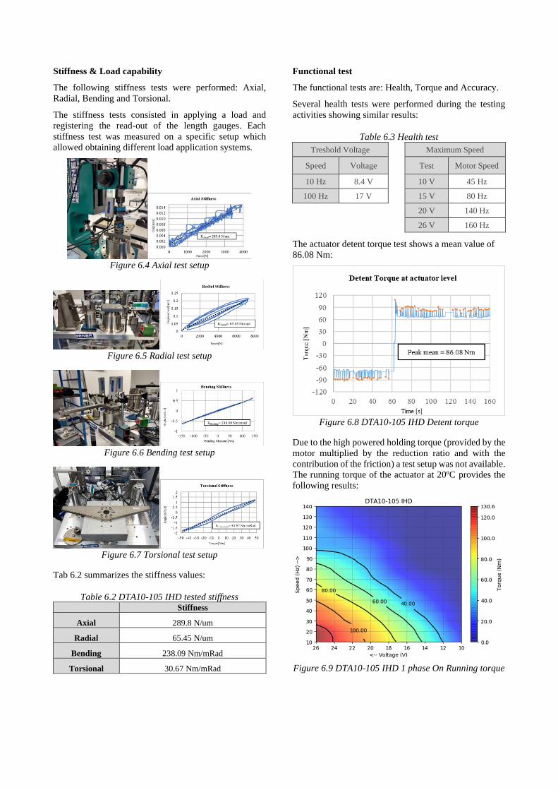
Stiffness & Load capability
The following stiffness tests were performed: Axial,
Radial, Bending and Torsional.
The stiffness tests consisted in applying a load and
registering the read-out of the length gauges. Each
stiffness test was measured on a specific setup which
allowed obtaining different load application systems.
Figure 6.4 Axial test setup
Figure 6.5 Radial test setup
Figure 6.6 Bending test setup
Figure 6.7 Torsional test setup
Tab 6.2 summarizes the stiffness values:
Table 6.2 DTA10-105 IHD tested stiffness
Stiffness
Axial 289.8 N/um
Radial 65.45 N/um
Bending 238.09 Nm/mRad
Torsional 30.67 Nm/mRad
Functional test
The functional tests are: Health, Torque and Accuracy.
Several health tests were performed during the testing
activities showing similar results:
Table 6.3 Health test
Treshold Voltage
Maximum Speed
Speed Voltage
Test Motor Speed
10 Hz 8.4 V
10 V 45 Hz
100 Hz 17 V
15 V 80 Hz
20 V 140 Hz
26 V 160 Hz
The actuator detent torque test shows a mean value of
86.08 Nm:
Figure 6.8 DTA10-105 IHD Detent torque
Due to the high powered holding torque (provided by the
motor multiplied by the reduction ratio and with the
contribution of the friction) a test setup was not available.
The running torque of the actuator at 20ºC provides the
following results:
Figure 6.9 DTA10-105 IHD 1 phase On Running torque
The accuracy and command tests are to be performed.
However, considering the accuracy of the sum motors
and the HD together with the zero backlash, small
variation is expected.
Environmental testing
The qualification campaign needs to be completed,
however the heritage of the las decade within the rotary
actuators and the similarity of the components already
anticipate the success of the testing campaign.
7. LESSONS LEARNED
- The magnetic design and improvement of the motor
is critical to provide the requested performances
- The development of capabilities/tools for the design
of every component is of paramount relevance
- The manufacturing of the pieces and components
need to be very carefully pursued
8. CONCLUSIONS
The new DTA10-105 IHD actuators include a tailored
Harmonic Drive® Gear, which allows to fit a modified
HD size 25 gear within the rotary actuator while keeping
the requested performances of mass & volume of the
medium size actuators (Ø120/4.7 inch and ~2.5kg/5.2
pounds). This way, the minimum torsional stiffness with
low loads (typically identified with K1) rise from 12.000
Nm/rad (of HD size 20 gears) to more than 30.000
Nm/rad (of HD size 25 gears). This ratio on the torsional
stiffness decreases the position uncertainty (deflection)
under a typical in orbit load of ~5Nm from more than 4
motor steps to slightly over 1.
Additionally, due to the SUM69 motor evolution; the
resulting provided unpowered holding torque of the
rotary actuator goes beyond 80 Nm with 6.25 mdeg/step
(1/160); being its source purely magnetic
(temperature/life independent).
The powered torque characteristics are also beyond the
rotary actuators of its size, providing much more than 100
Nm at ambient conditions with a very low power
consumption.
The final result of the development is a very competitive
rotary actuator for the space market, especially for those
applications were huge loads need to be withstood in
unpowered conditions and the stiffness plays a key role
(such as antenna pointing mechanisms).
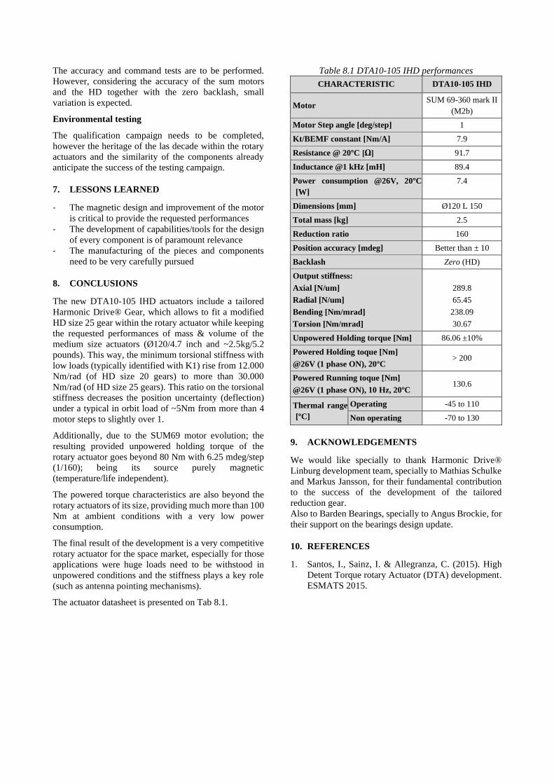
The actuator datasheet is presented on Tab 8.1.
Table 8.1 DTA10-105 IHD performances
CHARACTERISTIC DTA10-105 IHD
Motor SUM 69-360 mark II
(M2b)
Motor Step angle [deg/step] 1
Kt/BEMF constant [Nm/A] 7.9
Resistance @ 20ºC [Ω] 91.7
Inductance @1 kHz [mH] 89.4
Power consumption @26V, 20ºC
[W]
7.4
Dimensions [mm] Ø120 L 150
Total mass [kg] 2.5
Reduction ratio 160
Position accuracy [mdeg] Better than ± 10
Backlash Zero (HD)
Output stiffness:
Axial [N/um]
Radial [N/um]
Bending [Nm/mrad]
Torsion [Nm/mrad]
289.8
65.45
238.09
30.67
Unpowered Holding torque [Nm] 86.06 ±10%
Powered Holding toque [Nm]
@26V (1 phase ON), 20ºC > 200
Powered Running toque [Nm]
@26V (1 phase ON), 10 Hz, 20ºC 130.6
Thermal range
[ºC]
Operating -45 to 110
Non operating -70 to 130
9. ACKNOWLEDGEMENTS
We would like specially to thank Harmonic Drive®
Linburg development team, specially to Mathias Schulke
and Markus Jansson, for their fundamental contribution
to the success of the development of the tailored
reduction gear.
Also to Barden Bearings, specially to Angus Brockie, for
their support on the bearings design update.
10. REFERENCES
1. Santos, I., Sainz, I. & Allegranza, C. (2015). High
Detent Torque rotary Actuator (DTA) development.
ESMATS 2015.