DRAFT INDIAN STANDARD SELECTION, INSTALLATION, OPERATION ...siema.org/events/docs/25.pdf · DRAFT...
25
DRAFT IS 14536 Page 1 of 25 PROPOSED DRAFT INDIAN STANDARD SELECTION, INSTALLATION, OPERATION AND MAINTENANCE OF SUBMERSIBLE PUMPSET – CODE OF PRATICE (First revision) 1. Scope: This standard lays down the general guidelines for selection, installation, operation and maintenance of borewell submersible pumpsets covered in IS 8034 and Openwell Submersible pumpsets covered in IS 14220. 2. References The Indian standards listed below are necessary adjuncts to this standard Sl No. Indian Standards Title i) 694 : 1990 PVC insulated cables for working voltages up to and including 1100V (third revision) ii) 1239(Part 1) : 1990 Mild steel tubes, tubulars and other wrought steel fittings: Part 1 Mild steel tubes (fifth revision) iii) 4984 : 1995 High density polyethylene pipes for potable water supplies (fourth revision) iv) 4985 : 1988 Specification for unplasticised PVC pipes for potable water supplies (second revision) v) 8034 : 1989 Specification for submersible pumpsets (first revision) vi) 9283 : 1995 Motors for submersible pumpsets (first revision) vii) 10804 : 1994 Recommended pumping system for agricultural purposes (second revision) Viii) 12231 : 1987 UPVC (rigid) pipes for use in suction and delivery lines of agricultural pumps. iX) 14220 : 1994 Specification- Openwell Submersible pumpsets 3.Terminology 3.1. Induction Motor An alternating-current motor without a commutator, in which one part only, either the rotor or the stator, is connected to the supply network, the other working by induction. 3.2. Squirrel cage induction motor An induction motor in which the rotor windings comprise of bars in a laminated core with their ends short-circuited by end rings
Transcript of DRAFT INDIAN STANDARD SELECTION, INSTALLATION, OPERATION ...siema.org/events/docs/25.pdf · DRAFT...
DRAFT IS 14536 Page 1 of 25
PROPOSED
DRAFT INDIAN STANDARDSELECTION, INSTALLATION, OPERATION AND MAINTENANCE OF
SUBMERSIBLE PUMPSET – CODE OF PRATICE(First revision)
1. Scope:
This standard lays down the general guidelines for selection, installation, operation andmaintenance of borewell submersible pumpsets covered in IS 8034 and OpenwellSubmersible pumpsets covered in IS 14220.
2. References
The Indian standards listed below are necessary adjuncts to this standard
Sl No. Indian Standards Title
i) 694 : 1990 PVC insulated cables for working voltages up toand including 1100V (third revision)
ii) 1239(Part 1) : 1990 Mild steel tubes, tubulars and other wrought steelfittings: Part 1 Mild steel tubes (fifth revision)
iii) 4984 : 1995 High density polyethylene pipes for potable watersupplies (fourth revision)
iv) 4985 : 1988 Specification for unplasticised PVC pipes forpotable water supplies (second revision)
v) 8034 : 1989 Specification for submersible pumpsets (firstrevision)
vi) 9283 : 1995 Motors for submersible pumpsets (first revision)
vii) 10804 : 1994 Recommended pumping system for agriculturalpurposes (second revision)
Viii) 12231 : 1987 UPVC (rigid) pipes for use in suction and deliverylines of agricultural pumps.
iX) 14220 : 1994 Specification- Openwell Submersible pumpsets
3.Terminology
3.1. Induction Motor
An alternating-current motor without a commutator, in which one part only, either the rotor orthe stator, is connected to the supply network, the other working by induction.
3.2. Squirrel cage induction motor
An induction motor in which the rotor windings comprise of bars in a laminated core withtheir ends short-circuited by end rings
DRAFT IS 14536 Page 2 of 25
3.3. Types of submersible motors
3.3.1. Wet type submersible motors
It is a motor, which is completely filled with clear water or oil or emulsion of water and oil.
3.3.2. Resin filled submersible motors
It is a motor, where stator winding is encapsulated and filled with an insulating compound.The remaining portion is filled with water or oil.
3.3.3. Sealed submersible motors
It is a motor, where the winding as well as entire remaining space within the motor is filledwith air or suitable grade of oil and effectively sealed.
3.4. Capacitor Start Capacitor Run Motors (CSCR)
These motors have characteristics similar to those covered by capacitor-start induction-runmotors but are more applicable where a greater degree of quietness or a higher efficiencyand power factor are desirable.
3.5. Capacitor Start and Run Motors (CSR)
These motors are for use where low starting torque is acceptable. They are also generallyquieter than split-phase or capacitor-start induction-run motors.
3.6. Direct on line starting
A method of starting, applicable to three phase squirrel-cage motors, by connecting of themotor windings directly to the mains.
3.7. Star Delta staring
A method of staring applicable to the delta connected three-phase squirrel cage motors. Itconsists of connecting the three-phases temporarily in star connection while starting.
3.8. Auto transformer starting
A method of staring applicable to three-phase squirrel cage motor, by connecting the three-phase temporarily through an auto-transformer so as to reduce the applied Voltage at thetime of starting.
3.9. Circuit breaker
A mechanical switching device having two positions one of rest and the other capable ofmaking, carrying and breaking currents under normal circuit conditions carrying for a giventime and also breaking currents under abnormal circuit conditions, such as those of short-circuit.
3.10. Isolator (Disconnector)
A device used to open (or close) a circuit when either negligible current is interrupted (orestablished), or when no significant change in the voltage across the terminals of each pole
DRAFT IS 14536 Page 3 of 25
of the isolator occurs in the open position, it provides an isolating distance between theterminals of each pole
3.11. Under Voltage release
A release which permits a mechanical switching device to open or close without delay whenthe voltage across the terminals of the release falls below a predetermined value.
3.12. Over Voltage release
A release which permits a mechanical switching device to open or close without delay whenthe voltage across the terminals of the release rises above a predetermined value.
3.13. Over-Current Release Medium voltage
A release which permits a mechanical switching device to open with without delay when thecurrent in the release exceeds a predetermined value.
3.14. Medium Voltage
Any voltage normally exceeding 250 volts and not normally exceeding 650 volts.
3.15. Voltage Drop
In the motor circuits, the size of conductors shall be so chosen that the voltage at theterminals of the motor, when running under full load conditions, is not less than 97 percent ofthe declared voltage at the consumer’s supply terminals. Furthermore, when the starting oraccelerating current is considerably in excess of the full-load current, it may be necessary inorder to ensure adequate starting and accelerating torque to consider the conductor sizes inrelation to the voltage drop that may occur at the motor terminals when the excess current isflowing.
3.16. Types of pump
3.16.1. Radial flow pumps
In this type of pump, the water enters the impeller eye axially and leaves the impeller in theradial direction with higher velocity. The kinetic energy of the water is converted to pressureenergy in the diffuser and the water is again redirected axially into the next stage impellereye. For a borewell size, lower discharge rate pumping is achieved by radial flow typepumps and the required power, HP per stage is in the lower range.
3.16.2. Mixed flow pumps
In this type of pump, the water enters the impeller eye axially and leaves the impeller in thediagonal direction with higher velocity. The kinetic energy of the water is converted topressure energy in the bowl type diffuser and the water is again redirected axially into thenext stage impeller eye. For a borewell size, higher discharge rate pumping is achieved bymixed flow type pumps and the required power HP per stage is in the higher range.
3.17. Diffuser
This is a part in the pump which converts the velocity head of water imparted by the impellerin to pressure head.
DRAFT IS 14536 Page 4 of 25
3.18. Thrust Bearing
A hydro-dynamic thrust bearing is fitted in the base of the borewell motor to take care theaxial unbalanced thrust load of all the pump impellers.
3.19. Water Hammer
It is the effect experienced inside the piping system when the running pump is stopped. Ahigh pressure surge or shock wave is traveling at high velocity inside the water column backand forth which may damage the piping and pumpset. A non return valve is used tosafeguard the pump and motor thrust bearings from the effects of water hammer.
3.20. Draw down
It is the elevation difference between the depth of static water level and the consistentstanding water level in the tube well or rock well during pumping operation.
3.21. Draw down Level
It is depth of consistent standing water level below the ground level in the tube well or rockwell during pumping operation.
3.22. Static Water Depth
It is the depth of water level below the ground level when the pump is not in operation
3.23. Submergence
It is the minimum height of water level after draw-down above the inlet casing, while running.
3.24. Yield Testing
It is recommended to perform yield testing for the borewell.Yield testing is the process toestimate the yield of a borewell. This will assist in selection of a suitable capacity pump(lower capacity pumpset) without over-pumping of the borewell. This test shows the balancebetween amount of water that can be pumped out of the borewell and the amount of waterthat recharges back into the borewell from the surrounding groundwater source. This testrequires continuous pumping of the borewell for an extended period of time. During thepumping period, measurements are made to find out the rate at which the water is beingpumped out of the borewell and the depth to which the water level is lowered in the well asthe result of pumping known as Draw down Level. Refer Fig 13 for the borewell yield testingusing test pumpset.
3.25. Borewell
Borewell is a very deep narrow hole in the ground made in order to get water.
The borewell should be straight in relation to the pumpset. The borewell should be testedthroughout its depth with a pattern with overall length and diameter equal to the maximumdimensions of the pumpset.
3.26. Openwell
It covers ordinary open wells of varying dimension dug or sunk from the ground surface intowater bearing stratum to extract water for irrigation purposes. These are broadly masonry
DRAFT IS 14536 Page 5 of 25
wells and dug-cum bore wells. All such schemes are of private nature belonging to individualcultivator.
4.Exchange of Information
4.1 The electrical engineer responsible for the installation of the pumpset and equipmentcovered by this code shall be informed, by the persons requiring the pumpset andequipment, as to the exact duties, the location and conditions under which it is expected tooperate. This information should, if possible, be exchanged before the construction of theborewell and before any electrical equipment is ordered, thus enabling the electricalengineer to detail any special construction of the borewell features required and to specifythe most suitable type of pumpset and equipment for the operational requirement involved.
4.2 Details of the electric supply available and of any special requirements regarding theratings of equipment and conditions under which the equipment may be connected to thesupply should be ascertained from the supply authorities.
5.General Requirements
5.1 Standard Specifications
This code applies primarily to motors and pumpsets covered by IS 9283:1995, IS 14220:1994 and IS 8034:2002. It also presupposes the use of control-gear and other associatedequipment and connections complying with relevant Indian Standard or, where these are notavailable, with other approved standards.
5.2 Interchangeability
Where a number of similarly rated units are to be used, arrangements should preferably bemade for such units to be interchangeable as regards essential dimensions, such as thoseaffecting the fixing arrangement, space occupied, etc.
5.3 Compliance with Indian Electricity Rules and Other Regulations
5.3.1 All electrical installations shall be checked for compliance with the requirements of thecurrent Indian Electricity Rules and Regulations made there under together with any otherregulations that may be applicable. It is recommended that the local authority concerned inthe administration of the rules regulations in the matter of the layout of the installation ofmedium voltage industrial motor and their control-gear be consulted to ensure that therequirements under the rules and regulations are complied with.
5.3.2 The electrical installation shall be carried out by competent persons to undertake suchworks under statutory regulations that may be in force in different states.
5.3.3 Earth Connection
The frame of every motor and its associated control-gear shall be earthed by two separateand distinct connections with earth through an earth electrode. Where practicable, the earthconnection should be visible for periodical inspection.Earthing shall be done in accordancewith IS 732 (Part 2):1983.Reference is also invited to IS 3043:1987 for earthing equipment.A suitable means of isolating the supply shall be placed near each and every motor, so thatsupply to the motor can be completely cut off by means of it, when required. All wiring shallbe done in accordance with IS 732 (Part 2):1983.

DRAFT IS 14536 Page 6 of 25
6.Selection criteria of pumpset
6.1. Application of Bore well submersible pumpset.
Borewell Submersible pumps are suitable for applications like Agricultural farms, Sprinklerirrigation, Drip irrigation, Water supply for Industrial / Commercial Establishments, villagesetc
6.2. Borewell size
Major use of submersible pumpsets is by way of installation in bore wells and hence, thediameter of the borewell determines the size of pumpset according to its suitability with theborewell size.
Type of borewell like deep well/shallow well and position of strainer pipe are to be mentionedby the purchaser, so that pumpset is not lowered against strainer pipe. Accordingly thelowering depth is decided.
For safe erection and removal of the submersible pumpsets and subsequently to maintainsuitable suction flow velocity in remaining ring section between the unit and tubewell casing,maximum outside diameter of the pumpsets with respect to tubewell diameters arerecommended as given in Table 1.
Table 1 Maximum Outside Diameter of submersible PumpsetNominal Diameter
of the TubewellMaximum Outside Diameter of
Submersible PumpsetsCorresponding Minimum
Diameter of checking Mandrelmm mm mm(1) (2) (3)100 98 102115 108 117150 146 152200 196 202250 245 252300 296 302
NOTES1. The size and straightness of the bore well should be checked by a mandrel with minimumdia given in col 3 of Table 1 and of length minimum equal to the length of the pumpset.2. The drill bit size used for drilling the borehole should be such that the checking mandrel islowered up to the end of borehole and taken out of it easily.
6.3. Discharge
The yield of the borewell shall be tested by the drilling contractors and a report is furnishedby them regarding the continuous availability of water and its level when a certain quantity ofwater is being pumped out from the borewell. To ensure longer life and optimum efficiency ofthe borewell, it is recommended that the rated discharge of the pump should be taken asapproximately 85 percent of the yield of the borewell. Thus, the discharge of the pump isdecided. From various types of pumps available in the manufacturing range, a suitable typeof pump is selected, based on borewell size and required discharge, which gives maximumefficiency at that particular point.
DRAFT IS 14536 Page 7 of 25
6.4. Total Head
The total head shall be worked out by considering the following aspects.Level of water below the ground level when the rated/desired discharge is being pumpedout.Variation of water level taking place in season.Delivery head above ground level that is vertical height of the top most delivery point ofwater from the ground level.Frictional losses taking place in bend, nonreturn valve, reducers, gate valve, column pipeand delivery pipe depending upon size and length and type of pipe.
Addition of all the above gives the total head at which the desired pumpset will be working.
6.5. Stage and rating of pumpset
For the desired head and with selected type of pump, number of stages required is knownfor the type of pump. The number of stages gives the corresponding rating of motor byreferring to the performance chart/characteristic curves given by manufacturer.
7.Cable Selection
It is recommended that the cable size is selected from the cable selection charts in Table 3and Table 4 provided by the pumpset manufacturer, based on motor current and the lengthof the cable required. If the chart is not provided by the pumpset manufacturer it isrecommended that the maximum voltage drop for the motor current should not exceed 3percent of the supply voltage from the control panel to the motor terminal. If due to longerlength of cable for a particular current, the point is at the end of boundary of selection chartfor that size of cable, then next higher size of cable shall be selected. This will enable themotor to work satisfactorily as the voltage drop between supply point and motor terminalswill be minimal and overheating of winding will be reduced thereby increasing the life ofmotor.
Note – For motor with star delta starting, the current to be taken for cable size selection isthe phase current which is 0.58 x line current.
7.1. Cable Joint
The cable jointing is a critical parameter for performance, safety and service life of the pump.The cable jointing shall be done strictly as per pump manufacturer’s instructions and theinsulation resistance and the strength of the joint is thoroughly checked.
8.Selection of pipe, material and size
Normally the minimum size of delivery pipe shall be at least equal to the pumpset nominaloutlet size. But to reduce frictional losses in the pipe, higher diameter of pipes may be usedas provided in IS 10804. Accordingly other supporting clamps and cable clips shall also bespecified depending upon the diameter of the pipe selected.
9.Power supply Single or three phase
9.1. Single phase Motor
The voltage is the potential difference between the Phase and Neutral, generally it is 240V.A motor which operates in single phase alternating current power supply.
DRAFT IS 14536 Page 8 of 25
9.2. Three phase Motor
The voltage is the potential difference between two Phases. Normally it is 415V.A motorwhich operates in three phase alternating current power supply.
10.Protection devices – for Motor
The arrangement of a motor circuit and the type of its protection and control apparatus varyaccording to the size and duty of the motor, but the safeguards should be observed inarranging the protective systems. Every motor shall be provided with a starter or othercontrol device complying with relevant Indian standard. The requirements of the supplyauthority, which may, in certain cases, permit direct-on-line starting without the need for anycurrent-limiting device,The protection devices are required to take care of:Starting and stopping,Overload,Under and over voltage,Single phasing in case of 3 phase pumpsets,Dry running preventer,Short circuit/lightning protection, andProper indicating instruments.
All the above accessories shall be mounted on a control panel.
10.1. Starters
A device (or assembly of devices) designed for starting the motor or controlling theapparatus.
10.2. Dry Running
The Pumpset shall not run without pumping the water. In case the pumpset runs under dryrun conditions, the pumping water lubricating bearings might be damaged.
10.3. Water level guard
A device used to protect the pumpset continuously running in dry running conditions. It shallbe connected between the control panel switchgears and the probe placed above thepumpset top most point.
10.4. Single Phase preventer
Three-phase motors may be damaged or may give rise risks if they continue to run aftersupply to one phase has been interrupted. Adequate means should, therefore, be providedto ensure automatic disconnection of the remaining phases of the supply in such acontingency.
NOTE – This protection is provided for by the normal over current trips, in the case of delta-connected motors, these trips should preferably be connected within the interconnection ofthe delta winding.
10.5. Selection of fuses
If the fuses selected are too small, there is danger of one fuse blowing before the motorstarter trips with consequent liability of damage to the motor due to operation on one phase
DRAFT IS 14536 Page 9 of 25
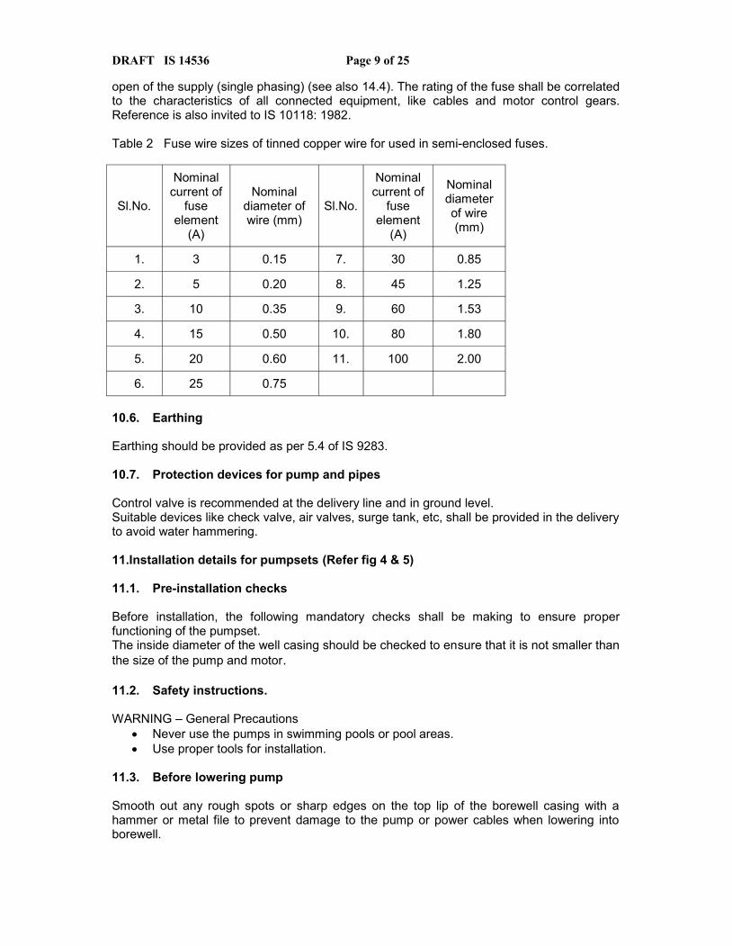
open of the supply (single phasing) (see also 14.4). The rating of the fuse shall be correlatedto the characteristics of all connected equipment, like cables and motor control gears.Reference is also invited to IS 10118: 1982.
Table 2 Fuse wire sizes of tinned copper wire for used in semi-enclosed fuses.
Sl.No.
Nominalcurrent of
fuseelement
(A)
Nominaldiameter ofwire (mm)
Sl.No.
Nominalcurrent of
fuseelement
(A)
Nominaldiameterof wire(mm)
1. 3 0.15 7. 30 0.85
2. 5 0.20 8. 45 1.25
3. 10 0.35 9. 60 1.53
4. 15 0.50 10. 80 1.80
5. 20 0.60 11. 100 2.00
6. 25 0.75
10.6. Earthing
Earthing should be provided as per 5.4 of IS 9283.
10.7. Protection devices for pump and pipes
Control valve is recommended at the delivery line and in ground level.Suitable devices like check valve, air valves, surge tank, etc, shall be provided in the deliveryto avoid water hammering.
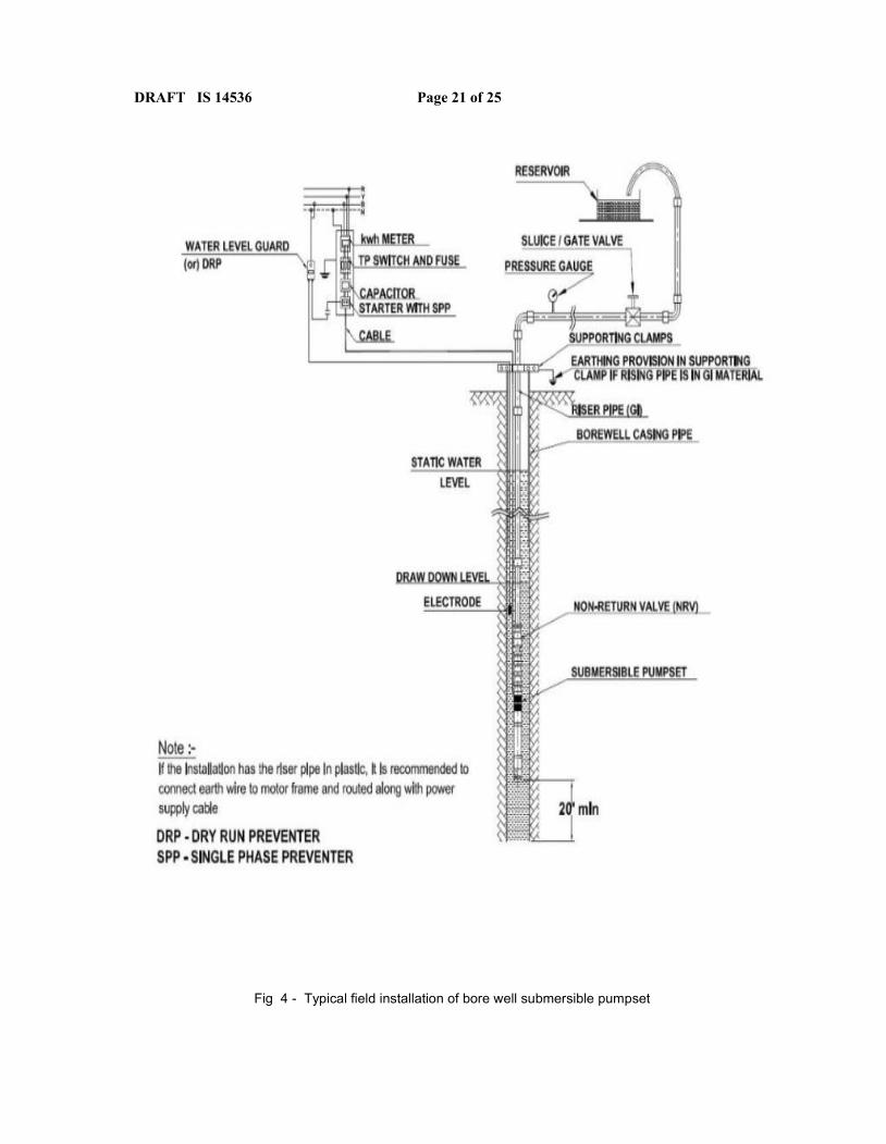
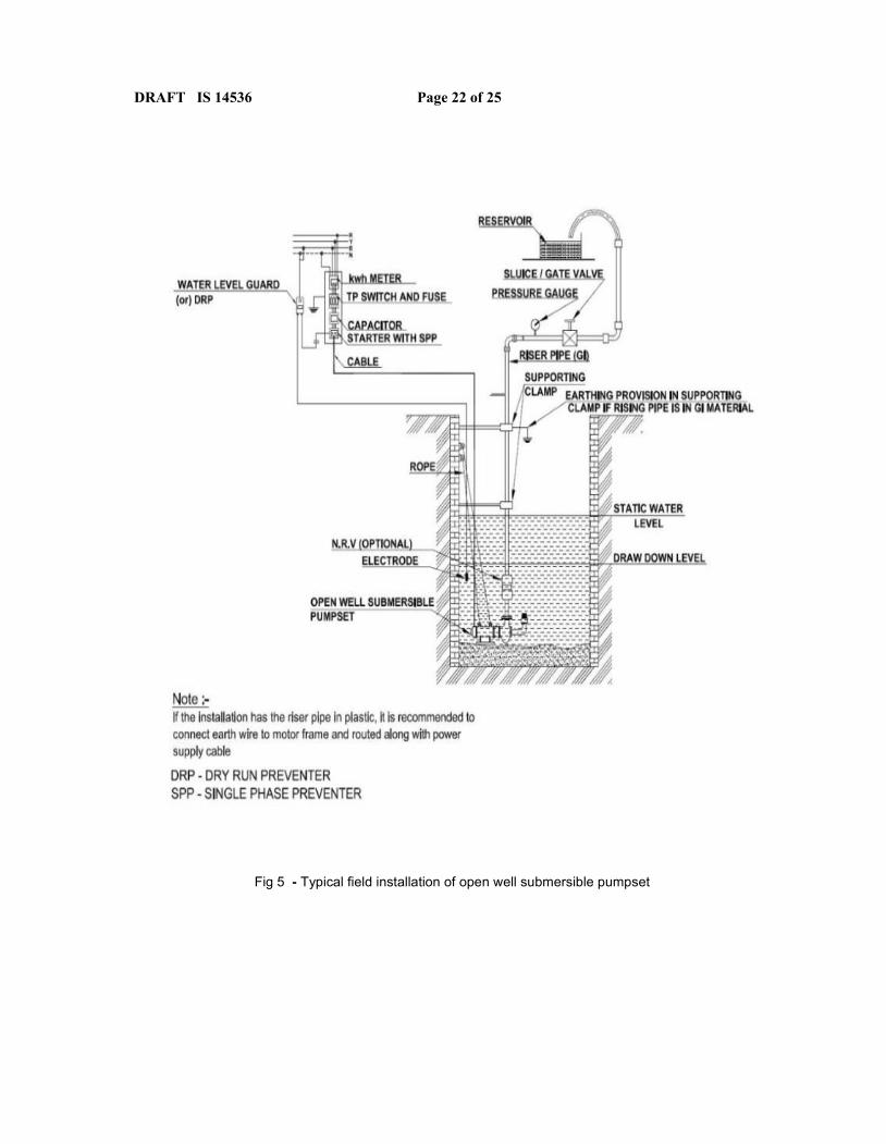
11.Installation details for pumpsets (Refer fig 4 & 5)
11.1. Pre-installation checks
Before installation, the following mandatory checks shall be making to ensure properfunctioning of the pumpset.The inside diameter of the well casing should be checked to ensure that it is not smaller thanthe size of the pump and motor.
11.2. Safety instructions.
WARNING – General Precautions Never use the pumps in swimming pools or pool areas. Use proper tools for installation.
11.3. Before lowering pump
Smooth out any rough spots or sharp edges on the top lip of the borewell casing with ahammer or metal file to prevent damage to the pump or power cables when lowering intoborewell.
DRAFT IS 14536 Page 10 of 25
The power cables and safety lifting rope shall be clamped to the pipe, straight up frombottom to top. Waterproof tape or nylon lock bands every 10 feet of pipe may be used.
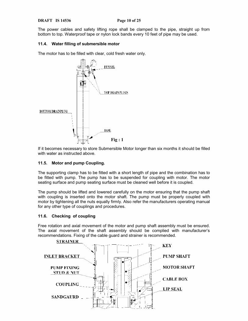
11.4. Water filling of submersible motor
The motor has to be filled with clear, cold fresh water only.
If it becomes necessary to store Submersible Motor longer than six months it should be filledwith water as instructed above.
11.5. Motor and pump Coupling.
The supporting clamp has to be fitted with a short length of pipe and the combination has tobe fitted with pump. The pump has to be suspended for coupling with motor. The motorseating surface and pump seating surface must be cleaned well before it is coupled.
The pump should be lifted and lowered carefully on the motor ensuring that the pump shaftwith coupling is inserted onto the motor shaft. The pump must be properly coupled withmotor by tightening all the nuts equally firmly. Also refer the manufacturers operating manualfor any other type of couplings and procedures.
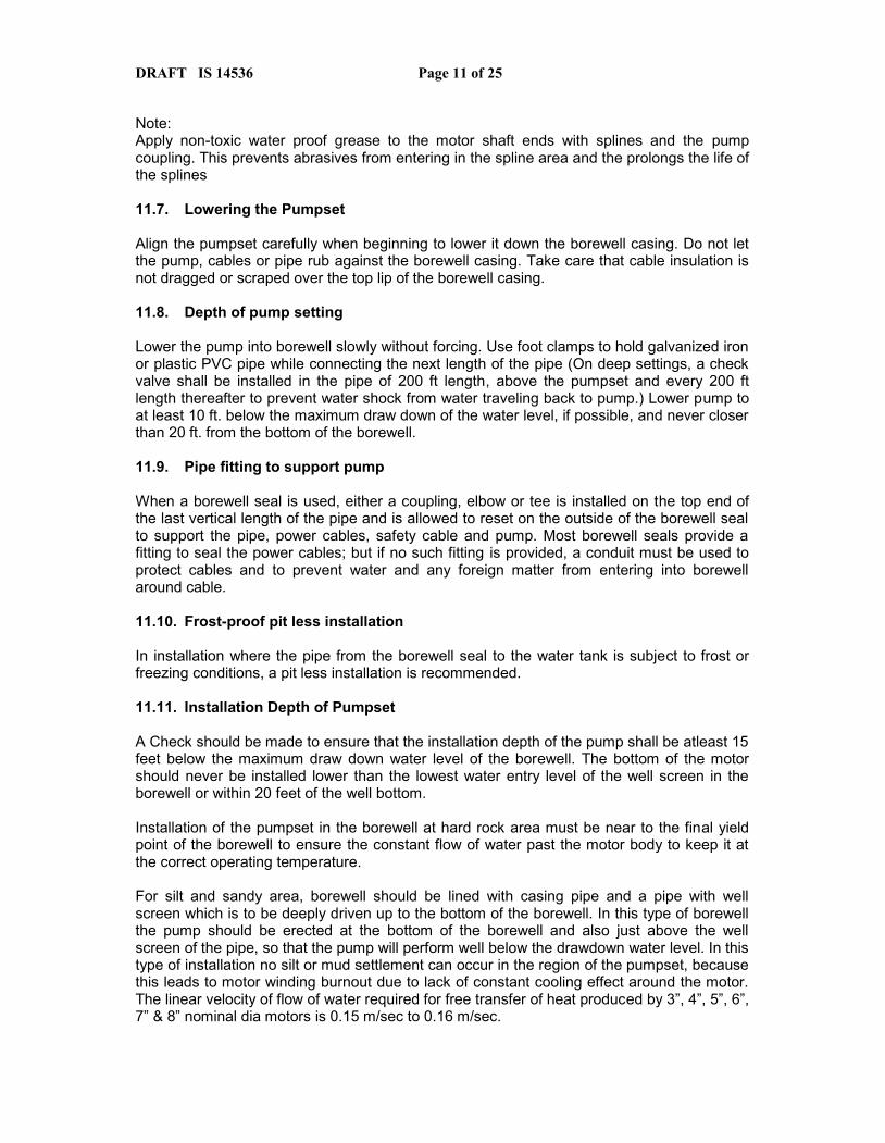
11.6. Checking of coupling
Free rotation and axial movement of the motor and pump shaft assembly must be ensured.The axial movement of the shaft assembly should be complied with manufacturer’srecommendations. Fixing of the cable guard and strainer is recommended.
Fig : 1
[Type a quote from the documentor the summary of an interestingpoint. You can position the textbox anywhere in the document.Use the Text Box Tools tab tochange the formatting of the pullquote text box.]
[Type a quote from the documentor the summary of an interestingpoint. You can position the textbox anywhere in the document.Use the Text Box Tools tab tochange the formatting of the pullquote text box.]
DRAFT IS 14536 Page 11 of 25
Note:Apply non-toxic water proof grease to the motor shaft ends with splines and the pumpcoupling. This prevents abrasives from entering in the spline area and the prolongs the life ofthe splines
11.7. Lowering the Pumpset
Align the pumpset carefully when beginning to lower it down the borewell casing. Do not letthe pump, cables or pipe rub against the borewell casing. Take care that cable insulation isnot dragged or scraped over the top lip of the borewell casing.
11.8. Depth of pump setting
Lower the pump into borewell slowly without forcing. Use foot clamps to hold galvanized ironor plastic PVC pipe while connecting the next length of the pipe (On deep settings, a checkvalve shall be installed in the pipe of 200 ft length, above the pumpset and every 200 ftlength thereafter to prevent water shock from water traveling back to pump.) Lower pump toat least 10 ft. below the maximum draw down of the water level, if possible, and never closerthan 20 ft. from the bottom of the borewell.
11.9. Pipe fitting to support pump
When a borewell seal is used, either a coupling, elbow or tee is installed on the top end ofthe last vertical length of the pipe and is allowed to reset on the outside of the borewell sealto support the pipe, power cables, safety cable and pump. Most borewell seals provide afitting to seal the power cables; but if no such fitting is provided, a conduit must be used toprotect cables and to prevent water and any foreign matter from entering into borewellaround cable.
11.10. Frost-proof pit less installation
In installation where the pipe from the borewell seal to the water tank is subject to frost orfreezing conditions, a pit less installation is recommended.
11.11. Installation Depth of Pumpset
A Check should be made to ensure that the installation depth of the pump shall be atleast 15feet below the maximum draw down water level of the borewell. The bottom of the motorshould never be installed lower than the lowest water entry level of the well screen in theborewell or within 20 feet of the well bottom.
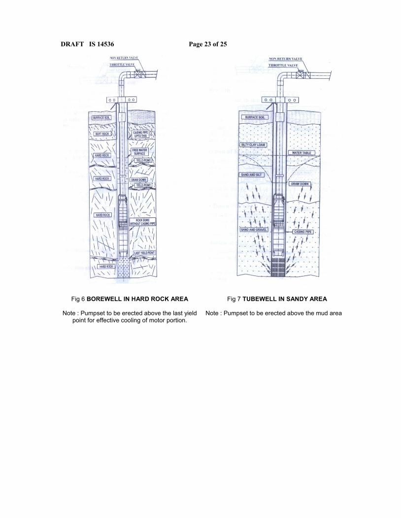
Installation of the pumpset in the borewell at hard rock area must be near to the final yieldpoint of the borewell to ensure the constant flow of water past the motor body to keep it atthe correct operating temperature.
For silt and sandy area, borewell should be lined with casing pipe and a pipe with wellscreen which is to be deeply driven up to the bottom of the borewell. In this type of borewellthe pump should be erected at the bottom of the borewell and also just above the wellscreen of the pipe, so that the pump will perform well below the drawdown water level. In thistype of installation no silt or mud settlement can occur in the region of the pumpset, becausethis leads to motor winding burnout due to lack of constant cooling effect around the motor.The linear velocity of flow of water required for free transfer of heat produced by 3”, 4”, 5”, 6”,7” & 8” nominal dia motors is 0.15 m/sec to 0.16 m/sec.
Fig: 2
DRAFT IS 14536 Page 12 of 25
11.12. Cable Type
The drop cable used between the submersible motor and capacitor box /starter should beapproved for submersible applications. Refer cable selection charts for recommended sizesof various cable lengths.
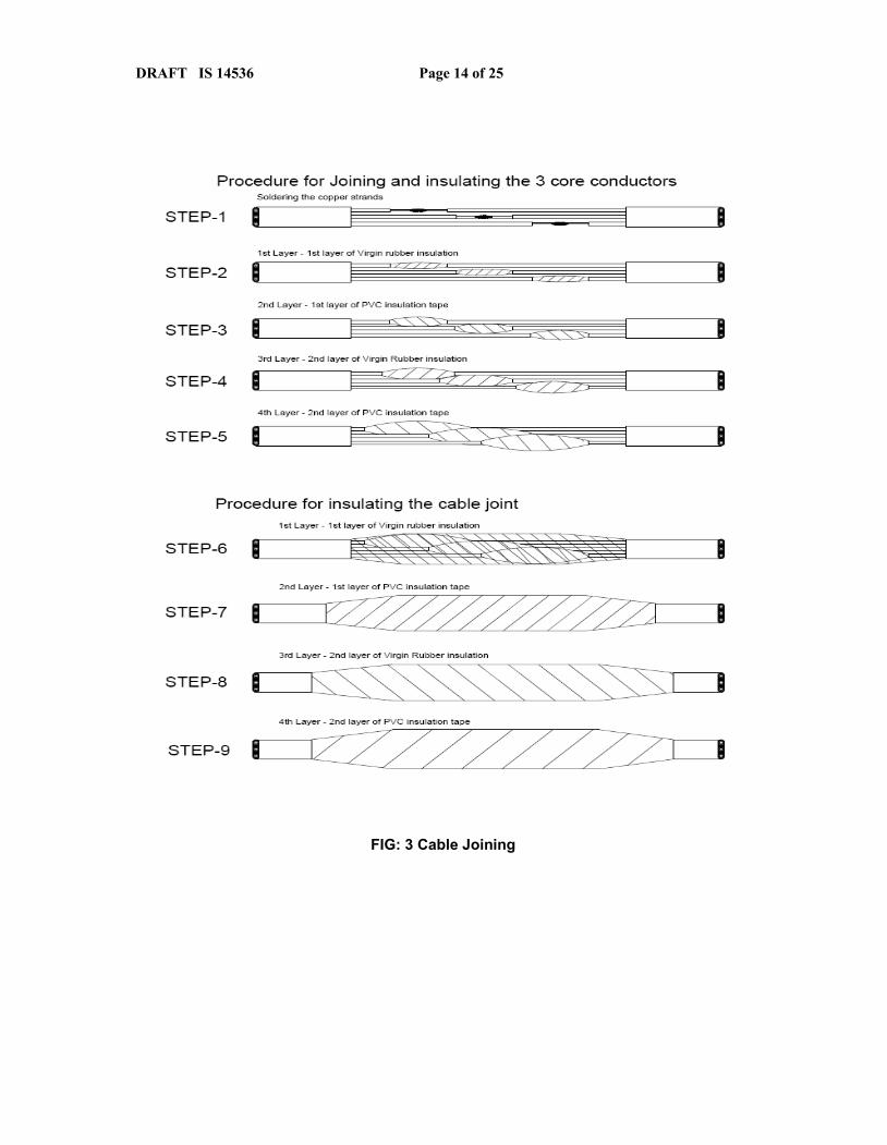
11.13. Cable joining procedure (Refer fig no : 3)
A good cable joint is important for proper functioning of the submersible pumpset and mustbe done with extreme care.If the joint is carefully made, it will work as good as any other portion of the cable and will becompletely water and air tight.This joint can be made with commercially available potting or heat shrink jointing kits.The joint should be made in accordance with the joint kit manufacturer’s instructions.Alternatively joint can be made with careful tape jointing as detailed below:
a) Check the motor cable and drop cable carefully for any damage.b) Cut the motor leads in a staggered manner. The end of the drop cable is to be cut so
that the ends match up with the motor leads. Be sure to match the colors of the eachcables.
c) 1 inch of insulation from each lead is to be stripped and trimmed off, making sure toscrap the wire bare to obtain a good connection. Be careful not to damage thecopper conductor when stripping off the insulation.
d) Insert a properly sized connector on each lead, making sure that lead colors arematched. Using crimping pliers, indent the copper lugs. Be sure to squeeze hard onpliers, particularly when using large cable. When connector O.D. is not as large ascable insulation, first build up with rubber electrical tape to the size of the cableinsulation.
e) Tape individual joints again with rubber electrical tape, using two layers; the firstextending two inches beyond each end of the conductor insulation , the second layertwo inches beyond the ends of the first layer. Wrap tightly, eliminating air spaces asmuch as possible.
f) Tape PVC electrical tape over the rubber electrical tape. Using two layers as in step5 and making each layer overlap the end of the proceeding layer overlap the end ofthe proceeding layer by atleast two inches. Total thickness of tape should not be lessthan the thickness of the conductor insulation.
g) To finish the cable jointing, combine the individual jointed leads together and tape thejointing area with atleast two layers of rubber electrical tape. The first extending twoinches beyond the each end of the drop cable main insulation end. The second layertwo inches beyond the ends of the first layer. Wrap tightly, eliminating air spaces.Tape two layers of PVC electrical tape over the rubber insulation, making each layeroverlap the end of the proceeding layer by atleast two inches.
h) To check the insulation of the joint, conduct megger test with 500v Megger bykeeping the joint in water.
DRAFT IS 14536 Page 13 of 25
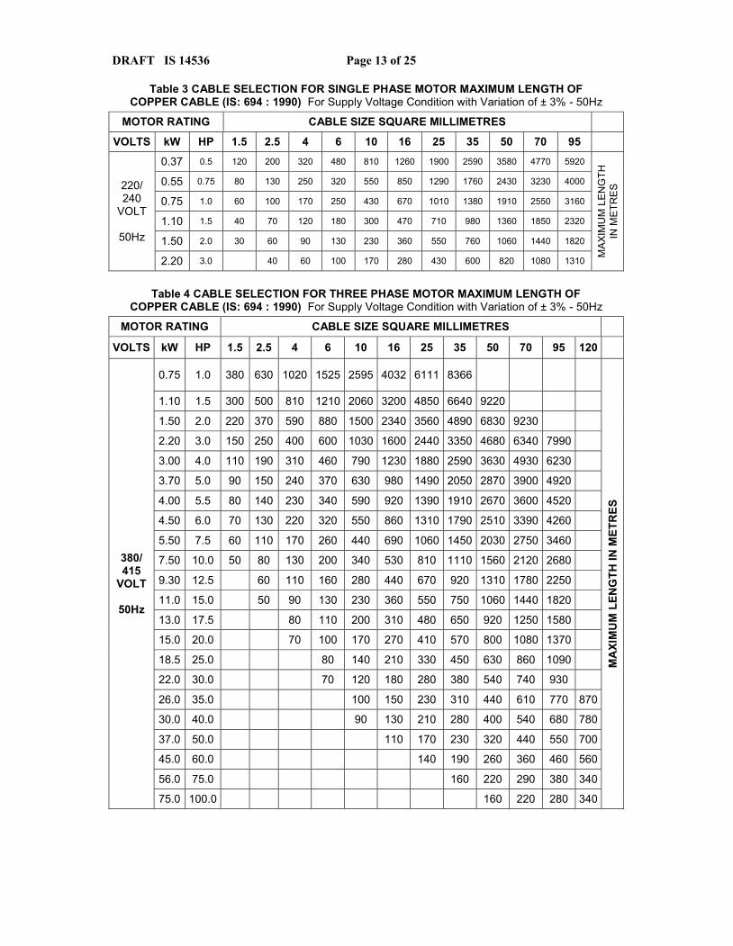
Table 3 CABLE SELECTION FOR SINGLE PHASE MOTOR MAXIMUM LENGTH OFCOPPER CABLE (IS: 694 : 1990) For Supply Voltage Condition with Variation of ± 3% - 50Hz
MOTOR RATING CABLE SIZE SQUARE MILLIMETRES
VOLTS kW HP 1.5 2.5 4 6 10 16 25 35 50 70 95
220/240
VOLT
50Hz
0.37 0.5 120 200 320 480 810 1260 1900 2590 3580 4770 5920
MA
XIM
UM
LE
NG
THIN
ME
TRE
S0.55 0.75 80 130 250 320 550 850 1290 1760 2430 3230 4000
0.75 1.0 60 100 170 250 430 670 1010 1380 1910 2550 3160
1.10 1.5 40 70 120 180 300 470 710 980 1360 1850 2320
1.50 2.0 30 60 90 130 230 360 550 760 1060 1440 1820
2.20 3.0 40 60 100 170 280 430 600 820 1080 1310
Table 4 CABLE SELECTION FOR THREE PHASE MOTOR MAXIMUM LENGTH OFCOPPER CABLE (IS: 694 : 1990) For Supply Voltage Condition with Variation of ± 3% - 50Hz
MOTOR RATING CABLE SIZE SQUARE MILLIMETRES
VOLTS kW HP 1.5 2.5 4 6 10 16 25 35 50 70 95 120
380/415
VOLT
50Hz
0.75 1.0 380 630 1020 1525 2595 4032 6111 8366
MA
XIM
UM
LEN
GTH
IN M
ETR
ES
1.10 1.5 300 500 810 1210 2060 3200 4850 6640 9220
1.50 2.0 220 370 590 880 1500 2340 3560 4890 6830 9230
2.20 3.0 150 250 400 600 1030 1600 2440 3350 4680 6340 7990
3.00 4.0 110 190 310 460 790 1230 1880 2590 3630 4930 6230
3.70 5.0 90 150 240 370 630 980 1490 2050 2870 3900 4920
4.00 5.5 80 140 230 340 590 920 1390 1910 2670 3600 4520
4.50 6.0 70 130 220 320 550 860 1310 1790 2510 3390 4260
5.50 7.5 60 110 170 260 440 690 1060 1450 2030 2750 3460
7.50 10.0 50 80 130 200 340 530 810 1110 1560 2120 2680
9.30 12.5 60 110 160 280 440 670 920 1310 1780 2250
11.0 15.0 50 90 130 230 360 550 750 1060 1440 1820
13.0 17.5 80 110 200 310 480 650 920 1250 1580
15.0 20.0 70 100 170 270 410 570 800 1080 1370
18.5 25.0 80 140 210 330 450 630 860 1090
22.0 30.0 70 120 180 280 380 540 740 930
26.0 35.0 100 150 230 310 440 610 770 870
30.0 40.0 90 130 210 280 400 540 680 780
37.0 50.0 110 170 230 320 440 550 700
45.0 60.0 140 190 260 360 460 560
56.0 75.0 160 220 290 380 340
75.0 100.0 160 220 280 340
DRAFT IS 14536 Page 14 of 25
FIG: 3 Cable Joining
DRAFT IS 14536 Page 15 of 25
12.Operation
12.1. Checks before Running the pumpset
After lowering the pumpset to the required level pumpset shall be commissioned carefully.Check the suitability of the incoming voltage, which should be the rated voltage.In case of 3 phase submersible pumpset, check whether all three phase supply voltage isbalanced or not. If not, do not start the pump.Ensure proper earthing is done at the ground level.If above parameters are checked and found all right, then the pump is ready to start.Before giving the supply to the pumpset the following shall be checked.
12.1.1. Visual inspection
The jumper connection of the Local authority (EB) shall be checked for looseconnection of wires, if any
The connection to the fuse carrier and the connection from the fuse carrier to themain switch and the wires from the main switch to control panel shall be checked forloose connections
The meters shall be checked for correctness. The over load relay range shall be checked to suite the pump capacity
12.1.2. Checking the panel board and main switch without connection.
The supply will be given to panel board via main switch and the supply in threephases shall be checked with voltmeter or glowing indicating lamps.
Before switching “ON” the panel the supply voltages shall be checked at the powerinput terminals of the strip connector (where the pumpset connecting lead cable shallbe connected).
Panel board is switched on and the volt meter reading and the voltage measured atstrip connector shall be equal.
The functioning of protection devices shall be checked for single phasing, phasereversal and dry running.
Switch off the pumpset control panel board and power input mains.
12.1.3. After connecting the lead cables of the pumpset to the panel board
Connect the earth wire and water level guard wires. The pumpset shall be switched ON. Start the pumpset with flow rate and the pressure gauge reading shall be checked to
ensure the proper direction of rotation. If the direction of rotation differs, the pumpset shall be switched off and the
connection shall be changed for the correct rotation, after wards the pumpset shallbe switched on.
The pressure gauge reading and the flow rate shall be measured and compared withprevious measurements.
If the discharge is more it is positive direction, if discharge is less it is reversedirection. Here once again the function of single phase preventer for single phasing,phase reversal and dry running shall be checked.
The functioning of over load relay shall be checked by reducing the ampere range inthe over load relay to less than the current taken by the pumpset.
The over load relay shall be checked for phase current in the case of star deltamotors and for line current in the case DOL motors.
DRAFT IS 14536 Page 16 of 25
Finally the current setting in the over load relay shall be fixed at 10% more than thecurrent taken by the pumpset
12.1.4. Change of depth of installation
While running the pumpset, the discharged water shall be collected with a clear glasscontainer when the pumpset installed at the bottom most point in the well and thewater shall be checked for contaminations if any.
If the water is contaminated with silt, abrasive material and metal parts wait for halfan hour and the quality of water shall be checked once again.
Throttle the delivery valve up to approximately 1/3 of rated discharge. Do not stop thepump till clear water starts coming out. Open the delivery valve fully after clear wateris obtained.
If the water is clear, the pumpset shall be kept at the same depth. If the water is contaminated the pumpset shall be raised by 3 to 6 meters above or
suitably. Once again the water shall be checked for contaminations. If the discharge reduces drastically the draw down is more and the pumpset shall be
lowered.
13.Maintenance and trouble shooting
13.1. Maintenance - Periodical checks
Pumps running at higher water table, water drainage, or under bad weather conditions shallbe examined more frequently.
13.1.1. General
When a submersible pumpset has been properly installed, it requires minimum attentionlater on to keep it working properly. All maintenance work should be done correctly under thesupervision of an experienced electrician.
The main aim of maintenance work should be to prevent trouble rather than allow it to occurand then deal with it. To achieve this, inspection at regular intervals should be carried outaccording to a schedule, and proper records should be kept of what has been done on eachoccasion.
13.2. Motors
13.2.1. Insulation Resistance
The insulation resistance of the winding and cable shall be checked periodically duringservice and where this is found to drop below 1mΩ/kV with a minimum of 1MΩ, the pumpsetshall be taken out for rectification.
13.3. Controllers, Starters.
The contacts and insulating part shall be kept thoroughly free from dirt and moisture andthere shall be firm metallic connection between fixed and moving contacts and fixed contactswhen they come in contact with each other.
DRAFT IS 14536 Page 17 of 25
Terminals and screw connections shall be kept clean and tight. If they become dirty orcorroded, they should be disconnected and all contact surfaces made clean and smooth.Bad contact leads to sparking and ultimate breakdown
Fuse contacts and terminals shall be examined periodically for cleanliness and tightness.When a fuse wire or strip has to be removed, care should be taken that the new one is of thecorrect combination and size.
13.3.1. Oil Filled Control Equipment
The insulating oil level in all oil-filled staring and control equipment shall be periodicallychecked and samples of the oil taken and tested for breakdown voltage, acidity andmoisture. If the tests indicate that the oil is unsatisfactory, it should be immediately replacedby new or reconditioned oil where small quantities of oil are involved, periodical replacementof the oil at intervals determined by experience and sampling tests may be adopted as analternative to periodical testing.
In the case of oil-filled equipment, such as switchgear and starters, arching takes placeunder the surface of the oil, carbon is formed, thus necessitating the periodic re-conditioningof the oil to remove the carbon. Such equipment should, therefore, be regularly inspectedand the oil reconditioned at the appropriate time.
Tanks or other enclosures for electrical apparatus, which have held oil may contain vapour inan explosive concentration, therefore naked flames or non-flameproof electrical equipmentshall not be used in such situations nor shall welding operations be under-taken either insideor outside such enclosures until all traces of vapour and oil have been removed.
13.4. Earthing
Periodic tests shall be made of the resistance of earth electrodes and of earth-continuityconductors to check the effectiveness of the earthing system.
The effectiveness of the earth-leakage protective devices, if provided, shall be periodicallychecked.
13.5. Safety Devices
Remote tripping devices and limit switches, which are provided for safety reasons but which,may not be called upon to function under normal operations which the interlocks aredesigned to prevent.
Interlocks designed to prevent unsafe operations shall be checked periodically by acompetent person by making a deliberate attempt to perform the operations which theinterlocks are expected to avoid.
Where an emergency supply as specified in IS 900 Clause 6.5 is provided, the source ofsupply and all ancillary apparatus shall be checked periodically.
13.6. Maintenance Schedule
A recommended schedule for periodical checks and maintenance of motors is given below
13.6.1. Daily maintenance
Visually examine earth connections and motor leads.

DRAFT IS 14536 Page 18 of 25
Examine control equipment.
Before starting read and note down the voltage in the record and only if the voltage is withinhe limit as specified, start the pumpset otherwise do not run the pumpset.
If voltage available is with-in the specified limit, then start the pumpset. Watch the currentdrawn by the pumpset in the Ammeter of the control panel or with the help of clamp meter.The current drawn by the pumpset must be well with-in the limits of the motor full loadcurrent. If the Current drawn is high, stop the pumpset.
Note down the current values in the record.
Check the engagement sound of the Contactor(s).
13.6.2. Weekly maintenance
Before Starting ensure the connected wires of the starter are not loose
Examine main switch and fuse carriers for loose connections
Visually inspect contactor(s) tips.
Generally check for any insects inside the starter for e.g. Lizard, Rat, Ants etc.
13.6.3. Monthly maintenance
Inspect and clean oil circuit breakers.
Insulation resistance should be checked once in a month in addition to daily and weeklymaintenance schedule
If oil circuit breakers are used, inspect and clean the oil condition.
Measure the flow of water by using volume method/V-notch method/Scale method and notedown the values in the record. If the flow rate is reduced beyond 10% of initial values, thepumpset may be taken out from the bore well and repaired for worn-out parts.
13.7. Records
Maintain a register giving one or more pages for each motor and record therein all importantinspection and maintenance works carried out from time to time. These records should showpast performance, normal insulation level, nature of repairs and time between previousrepairs and other important information which would be of help for good performance andmaintenance.
13.8. Trouble shooting
13.8.1. Less discharge
Operational system head is more than rated pump head. Yield of borewell not adequate. Lower speed of motor due to low voltage/low frequency/excessive friction. Chocking of strainer/impeller/pipes.
DRAFT IS 14536 Page 19 of 25
Delivery valve/NRV/Check valve not fully opened. Improper direction of rotation due to change in phase sequence of power supply. Leakage in delivery pipe. Excessive abrasive wear out of pump components
13.8.2. Pumps draw excessive power / current
Misalignment of pump and motor. Higher speed of motor due to higher supply frequency/excessive supply voltage. Duty point of the system not matching. Rubbing of rotating parts with stationery parts. Bearing worn out. One defective fuse, single phasing. Change in the actual static head. Low voltage. Cable in defective condition Loose connection of input supply
13.8.3. Excessive vibration
Improper alignment. Inadequate water level. Bearings worn out. Shaft bent. Abrasive wear of pump bearings after prolonged operation or due to operation in water of
higher sand content or corrosiveness. Foreign bodies lodged in impellers. Pump resting improperly on borewell bed. Air or gas inclusion in water. Dry running of pump. Reverse rotation.
13.8.4. Zero discharge
Failure of power supply. Operating head is beyond the range of pumpset. Pump not properly submerged in water. Strainer/impeller/delivery valve/check valve/NRV/pipe fully choked. Coupling broken.
13.8.5. Pump seizure
Improper alignment. Dry running of pump. Bend in shaft. Pump remains unused for prolonged period. Clogging of foreign matter. Bearing worn out
13.8.6. Wearing out parts
Misalignment. Presence of sand particles.
DRAFT IS 14536 Page 20 of 25
Improper selection of material. Frequent dry running. Quality of water.
13.8.7. Pump does not start
Tripping of overload relay. Low supply voltage. Pump seized No power supply. Blown fuse. Failure of protection devices. Failure of cables/cable joints
NOTE - To ensure correct operation it is necessary to have correct information given byvarious measuring instruments installed on control panel. Periodical checking and calibrationof the measuring instruments are necessary for proper and correct feedback.
DRAFT IS 14536 Page 21 of 25
Fig 4 - Typical field installation of bore well submersible pumpset
DRAFT IS 14536 Page 22 of 25
Fig 5 - Typical field installation of open well submersible pumpset
DRAFT IS 14536 Page 23 of 25
Fig 6 BOREWELL IN HARD ROCK AREA
Note : Pumpset to be erected above the last yieldpoint for effective cooling of motor portion.
Fig 7 TUBEWELL IN SANDY AREA
Note : Pumpset to be erected above the mud area

DRAFT IS 14536 Page 24 of 25
ANNEXURE “A”LIST OF REFERENCE STANDARDS
Sl.No. IS No. Description
1. 694 : 1990Polyvinyl chloride insulated unsheathed and sheathed cables/cords withrigid and flexible conductor for rated voltages up to and including450/750v
2. 1239 (Part 1):2004 Mild steel tubes, tubulars and other wrought steel fittings : Part 1 Mildsteel tubes (fifth revision)
3. 1239 (Part 2):2011 Mild steel tubes, tubulars and other wrought steels fittings. Part 2 Mildsteel tubulars and other wrought steel pipe fittings (third revision)
4. 2800 (Part 1) :1991 Code of practice for construction and testing of tubewells / BorewellsPart – 1 Construction
5. 2800 (Part 2) :1979 Code of practice for construction and testing of tubewells / BorewellsPart – 2 Testing
6. 4984 : 1995 Specification for high density polyethylene pipes for potable watersupplies; sewage and industrial effluents (third revision)
7. 4985 : 2000 Specification for unplasticised PVC pipes for potable water supplies(second revision)
8. 6595(Part 1):2002 Horizontal centrifugal pumps for clear, cold water:Part 1 Agricultural and rural water supply purposes (second revision)
9. 7347:1974 Performance of small size spark ignition engines foragricultural sprayers and similar applications
10. 8034 : 2002 Submersible pumpsets (first revision)
11. 9079:2002 Monoset pumps for clear, cold water for agricultural purposes (firstrevision)
12. 9283 : 1995 Motors for submersible pumpsets
13. 9694 (Part 1) : 1987Code of practice for the selection, installation, operation andmaintenance of horizontal centrifugal pumps for agricultural applications: Part 1 selection ( first revision)
14. 10124 (Part 8) : 1988 Specification for fabricated PVC fittings for potable water supplies : Part8 Specific requirements for 90 degree bends ( first revision)
15. 11346 : 2002 Testing set up for agricultural pumps
16. 11170:1985 Performance requirements for constant speed compression ignition(diesel) engines for agricultural purposes (up to 20 kW)
17. 11501:1986 Engine monoset pumps for clear, cold, fresh water foragricultural purposes
18. 12231 : 1987 Specification for Unplasticised PVC Pipes for use in Suction andDelivery lines of Agricultural pumpsets
19. 13593 : 1992 UPVC pipe fittings for use with UPVC pipes in the suction and deliverylines of agricultural pumps specification
20. 14220 : 1994 Openwell submersible pumpsets
21. 14536 : 1998This Standard lays down general guidelines for selection, installation,operation and maintenance of Borewell submersible pumpsets coveredin IS 8034.
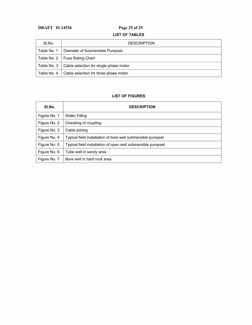
DRAFT IS 14536 Page 25 of 25LIST OF TABLES
Sl.No. DESCRIPTION
Table No. 1 Diameter of Submersible Pumpset
Table No. 2 Fuse Rating Chart
Table No. 3 Cable selection for single phase motor
Table No. 4 Cable selection for three phase motor
LIST OF FIGURES
Sl.No. DESCRIPTION
Figure No. 1 Water Filling
Figure No. 2 Checking of coupling
Figure No. 3 Cable joining
Figure No. 4 Typical field installation of bore well submersible pumpset
Figure No. 5 Typical field installation of open well submersible pumpset
Figure No. 6 Tube well in sandy area
Figure No. 7 Bore well in hard rock area