
Belt Scale Selection Installation Guide
22
BRISBANE SYDNEY
-
Upload
alejandro-barnechea-poblete -
Category
Documents
-
view
60 -
download
16
description
Seleccion de pesometros
Transcript of Belt Scale Selection Installation Guide

BRISBANE SYDNEY

Web–Tech are manufacturers and designers of :-
Company Profile Web-Tech is a wholly owned Australian company, which specialise in the design and manufacture of continuous and static weighing systems for all facets of industry. Web–Tech have 15 years experience in the field of continuous weighing. Web-Tech's Head office and manufacturing works are located in Brisbane, with a sales and service office in Sydney and Melbourne. We have a standard range of designs for equipment. Where a customer has a special requirement we will, where possible, modify our design. or design a new device to meet the application requirements. Our feeders are currently in use with most of the major companies in Australia and our electronic systems are widely used in the U.S.A., South America and Europe. Web-Tech is proud to include companies such as BHP Steel, BHP Minerals, BHP Temco, BHP Australia Coal, CSR Sugar & Plaster Board, Monier, Queensland Cement & Lime, Tomago Aluminium Company, Boyne Smelters Limited, Blue Circle Southern Cement, Swan, Cement, Boral, Comalco Aluminium, Incitec, Mt. Isa Mines Limited, Port Waratah Coal Services, Simplot, Uncle Bens, Kellogg ( Australia &, Malaysia ), and SPC amongst our users.
BRISBANE (Head Office) 11 Electronics Street Eight Mile Plains, QLD 4113, Australia. Tel + 61 7 3841 2844 Fax + 61 7 3841 0005 Email [email protected]
WEB–TECH Web page
www.web-tech.com.au
Weigh belt feeders Conveyor belt scales
Loss in Weight screw feeders Volumetric screw feeders
Loss in Weight vibratory feeders Gain in Weight vibratory feeders
SYDNEY OFFICE Tel + 61 2 9757 2296 Fax + 61 2 9899 6585 Email [email protected]
MELBOURNE OFFICE Tel + 61 3 9653 9260 Fax + 61 3 9653 9699 Email [email protected]

WEB-TECH AUSTRALIA PTY LTD
TABLE OF CONTENTS
1. BELT SCALE FUNCTIONS
2. THEORY OF OPERATION 3. BELT SCALE COMPONENTS 4. CONVEYOR DESIGN 5. WHICH MODEL BELT SCALE ? 6. ONGOING MAINTENANCE
© The information contained in this document remains the property of Web-Tech Australia Pty Ltd and should not be reproduced or disclosed
without their permission .
BELT SCALE SELECTION AND INSTALLATION GUIDE
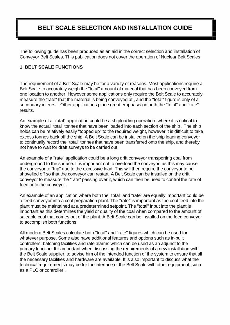
The following guide has been produced as an aid in the correct selection and installation of Conveyor Belt Scales. This publication does not cover the operation of Nuclear Belt Scales 1. BELT SCALE FUNCTIONS The requirement of a Belt Scale may be for a variety of reasons. Most applications require a Belt Scale to accurately weigh the "total" amount of material that has been conveyed from one location to another. However some applications only require the Belt Scale to accurately measure the "rate" that the material is being conveyed at , and the "total" figure is only of a secondary interest . Other applications place great emphasis on both the "total" and "rate" results. An example of a "total" application could be a shiploading operation, where it is critical to know the actual "total" tonnes that have been loaded into each section of the ship . The ship holds can be relatively easily "topped up" to the required weight, however it is difficult to take excess tonnes back off the ship. A Belt Scale can be installed on the ship loading conveyor to continually record the "total" tonnes that have been transferred onto the ship, and thereby not have to wait for draft surveys to be carried out. An example of a "rate" application could be a long drift conveyor transporting coal from underground to the surface. It is important not to overload the conveyor, as this may cause the conveyor to "trip" due to the excessive load. This will then require the conveyor to be shovelled off so that the conveyor can restart. A Belt Scale can be installed on the drift conveyor to measure the "rate" passing over it, which can then be used to control the rate of feed onto the conveyor . An example of an application where both the "total" and "rate" are equally important could be a feed conveyor into a coal preparation plant. The "rate" is important as the coal feed into the plant must be maintained at a predetermined setpoint. The "total" input into the plant is important as this determines the yield or quality of the coal when compared to the amount of saleable coal that comes out of the plant. A Belt Scale can be installed on the feed conveyor to accomplish both functions All modern Belt Scales calculate both "total" and "rate" figures which can be used for whatever purpose. Some also have additional features and options such as in-built controllers, batching facilities and rate alarms which can be used as an adjunct to the primary function. It is important when discussing the requirements of a new installation with the Belt Scale supplier, to advise him of the intended function of the system to ensure that all the necessary facilities and hardware are available. It is also important to discuss what the technical requirements may be for the interface of the Belt Scale with other equipment, such as a PLC or controller .

BELT SCALE SELECTION AND INSTALLATION GUIDE (CONT'D)
2. THEORY OF OPERATION Belt Scales enable material to be weighed on a conveyor whilst in motion. A Belt Scale differs from a static weighing system, such as a bin weighing system, in that the Belt Scale is required to measure two variables. The first variable is the actual weight on the conveyor belt, and the second variable is the actual belt speed or belt travel. The weight of material on the conveyor belt is obtained by measuring the load on one or more idlers. This load can then be expressed in terms of kg/metre (W) of belt. The belt speed or belt travel is measured by using a device which gives an output proportional to the belt speed (S) or belt travel (T) . The flow "rate" of material passing over the Belt Scale can be expressed as:
Rate = W x S
WEIGHT BELT SPEED
X = FLOW RATE (Weighframe) (Belt Speed
Sensor)
The "total" weight of material that has passed over the Belt Scale can be expressed as :
Total = W x T
WEIGHT BELT TRAVEL
(Weighframe) X (Belt Travel Sensor)
= TOTAL WEIGHT
Belt Scale manufacturers use either the belt speed or belt travel methods depending on their design philosophy. Those that use the belt travel method generally use a low frequency device, which delivers a number of pulses per unit of belt length. The integration primarily calculates the "total" weight, from which the flow "rate" is then derived. The second method is to use a high frequency device (up to 1 kHz) , the output of which is proportional to the belt speed . The integration primarily calculates the "rate" passing over the Belt Scale, from which the "total" is then derived. Due to the availability of high-speed processors, most modern Belt Scales use the "rate" method as the basis for their electronic design. Whilst the mathematics used by the Belt Scale electronics may appear to be relatively simple, the tasks required of the electronics are more complex. Not only must the electronics be capable of receiving and processing the signals from the weighing mechanism and belt speed / travel device, it must also be capable of the following: R Display Rate and Total readings

BELT SCALE SELECTION AND INSTALLATION GUIDE (CONT'D)
R Provide stable power supplies to the weighing and belt speed / travel elements R Provide analogue and digital outputs for remote equipment R Provide Automatic Zero and Span calibration facilities R Provide serial communications for remote computers R Carry out "AutoZero" routines when the belt is empty R Provide alarm functions R Provide control functions R Interface with the operator The measurement of the weight on the conveyor belt and the belt speed / travel also present some physical problems which must be overcome. The accuracy of the weight measurement is dependant on a number of factors such as belt tension, belt construction, weighframe location , troughing angle and material loading . The degree of accuracy, and ways of improving the accuracy are discussed in further detail in the following sections. 3. BELT SCALE COMPONENTS
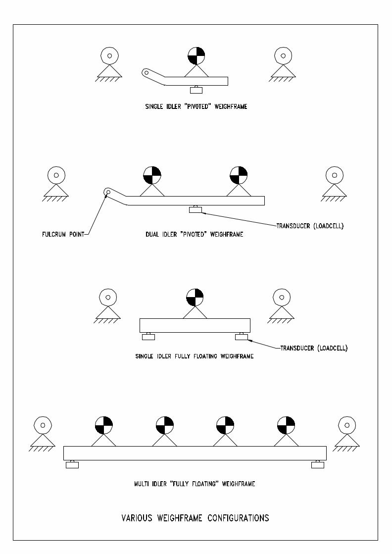
Basically Belt Scales consist of four main components. The main components are : i) Weighframe and associated weigh idlers ii) Belt speed / travel sensor iii) Electronic Integrator iv) Calibration device i) Weighframe and Weigh Idlers The function of the weighframe is to support the weigh idler(s) and conveyor belt, and to convert the weight of the material within the weigh span to an electrical signal, which can be processed by the electronics. Weighframes are varied in design, however the majority of the designs incorporate one or more transducers, most typically strain gauge loadcells .The weighframe is usually self contained, low profile, and designed to be installed within the limits of the conveyor structure. The number of idlers used is dependant upon the accuracy required, and the conveyor parameters. Various weighframe designs exist , each with their own perceived advantages . Most Belt Scale manufacturers use either a "pivoted" design or a "fully floating" design. With a "pivoted" design, one or more idlers are mounted on a frame, which is pivoted at one end by some form of fulcrum point. The fulcrum point is designed to be both maintenance free and as close to frictionless as possible. Early pivot designs included knife edges and bearings or ball bearings, however due to the perceived maintenance problems, and the advent of transducers with very small amounts of movement, these were replaced with components such as torque tubes , flexures or rubber trunnions.

BELT SCALE SELECTION AND INSTALLATION GUIDE
(CONT'D)
The "fully floating" design comprises one or more idlers mounted on a frame, which is in turn supported at each corner by a transducer. Horizontal and transverse restrainers limit the movement of the weighframe in any direction, except that perpendicular to the belt line.
The advantages of both types of design are as follows: PIVOTED TYPE FULLY FLOATING TYPE * Less Expensive * Same design as used in high accuracy static weighing systems * Require less transducers * Do not use pivots, which could influence measurements * Can be counterweighted which allows * Forces acting on weigh idlers act "deadweight" of belt and idlers to be directly on tranducers removed . Better sensitivity from the * Calibration weights represent the transducers same weight regardless of where *Less calibration weights required placed on weighframe Generally speaking, "fully floating" multi idler weighframes are normally used for high accuracy weighing applications, and "pivoted" single or multi idler weighframes are used for general purpose weighing applications. However similar performance can be achieved by installing two "pivoted" weighframes in series. Weigh Idlers The weighframe supports the belt by means of "Weigh Quality" idlers. The differences between these idlers and standard conveyor idlers are:
• The idler rolls are "in-line" rather than "offset" • The idler rolls are machined concentric to provide 0.13 mm Total Indicated Runout • The idler rolls are balanced within 0.011 Nm • The idler roll height can be adjusted
"Weigh Quality" idlers are also supplied for the two approach and two retreat idlers to the weighframe. Idler roll height is adjustable to allow for accurate alignment of the idlers within the weigh area. "Weigh Quality" idlers are available from most idler manufacturers The following design aspects should be confirmed when considering a proposed weighframe: R Self contained and preassembled for easy installation R Rigidity, with great emphasis placed on eliminating deflection R Provide minimal surface area for material build-up R Provide equal loading on all transducers

BELT SCALE SELECTION AND INSTALLATION GUIDE
(CONT'D)
R Provide maintenance free and frictionless pivot points R Be provided with mechanical "tare" facility for lightly loaded conveyors R Reduce the effects of material off centre loading ii) Belt Speed / Travel Sensor As previously discussed , a sensor is supplied to provide a signal to the electronic integrator as to the actual belt speed or belt travel . Belt Speed Sensor Belt speed sensors can be supplied in several arrangements. The most common method is for a "rotary" type sensor to mounted in an enclosure to be connected to a "live" shaft pulley , usually the tail pulley . As the pulley rotates, the speed sensor shaft is also rotated, which in turn produces a pulse output. The frequency of the pulse output is proportional to the rotational speed of the pulley. Typical frequencies fall within the range of 100 - 1000 Hz . Belt speed sensors should not be connected to the drive pulley, as any slippage between the drive pulley and conveyor belt will not be measured. A second type of belt speed sensor involves mounting a sprocket at the end of a conveyor roll , and sensing it's rotational speed with the use of a "Magnetic Pick-up" . The Magnetic Pick-up counts the number of sprocket teeth that pass by a sensing element, and therefore produces a frequency proportional to the speed. This system is not normally used on applications where the conveyor rolls are subject to material build-up, as this will change the diameter of the roll and therefore the indicated belt speed. However on some applications where the idler rolls appear to be carrying build-up, closer inspection will show that the area of idler roll in contact with the belt remains clean. The advantages of using the idler roll / sprocket type of sensor is that they are relatively simple and robust , and can be situated close to the weighframe . When installed close to the weighframe, the belt speed being measured is the actual belt speed at the weighframe. A third type of system still popular with some manufacturers / customers is the use of a pivoted "trailing" arm with a wheel in contact with the return belt. The wheel is attached to a rotary sensor similar to that used with the tail pulley method. The disadvantages of this method are: R The wheel is prone to bounce when a disturbance in the belt surface such as a splice
passes under it . This will cause a variation in frequency output, and therefore the measured belt speed.
R The wheel is usually mounted on the return belt adjacent to the weighframe. This can be a long distance away from the weighframe (by belt travel), and therefore the belt speed measured may not be the same belt speed at the weighframe.

BELT SCALE SELECTION AND INSTALLATION GUIDE (CONT'D)
Belt Travel Sensor A belt travel sensor usually consists of one or more "flags" welded to a pulley, usually the tail pulley, and a proximity probe. As the flags pass by the proximity probe they are counted, and this relates to the amount of conveyor belt that has passed around the pulley. The advantage of this type of system is that it is relatively simple and robust, however the disadvantage is that it is low frequency in output, and therefore the resolution can be coarse iii) Electronic Integrator The electronic integrator is designed to carry out the following basic functions: R Provide supply voltages to weighframe transducers and belt speed / travel sensors R Measure and integrate the instantaneous weight on weighframe and instantaneous
belt speed / travel which calculates the "Mass Rate" and "Mass Total" passing over the conveyor
R Provide analogue and pulse outputs for remote equipment R Provide facilities for calibration The electronic integrator may also provide the following options: R Provide P.I.D. control output R Provide serial communications for remote computers R Provide Rate alarm outputs R Provide batching facilities Most modern integrators are microprocessor based with computing power similar to a personal computer. Each manufacturer engineers their own software, which incorporates their own design philosophies. Whilst all integrators may look similar at first glance, the methods used by the various manufacturers to achieve the end-result, can vary significantly. The current "state of the art" integrators are designed to make operation / calibration easier for site personnel, and great emphasis should be placed on the ease of use. Many sites will prefer the Belt Scale supplier to carry out routine maintenance and calibration, however in an emergency-situation, there is nothing worse than having to wade through a manual, attempting to understand what a displayed code means. Integrator Location The electronic integrator does not have to be located adjacent to the weighframe. Some customers may wish to mount the integrator in a nearby motor control centre or in a control room. Whilst this is possible the following points should be considered when selecting the location:
• The weighframe transducers produce very low voltage levels and therefore if long cables are used voltage drops may occur
• The longer the cable run, the greater the chance of picking up electrical noise on the cables

BELT SCALE SELECTION AND INSTALLATION GUIDE (CONT'D)
• Long distances between weighframe and integrator increases the time required when carrying out calibrations
• Is the proposed area classified as Dust Ignition Proof or Hazardous? It is Web-Tech's belief that the best location for the integrator is adjacent to the weighframe where possible. The output signals can be used to provide information to remote equipment. The integrator should be mounted so that it is free from vibration, not subject to direct sunlight and rain. If installed outdoors it is suggested that rain / sun hoods are used. When selecting a Belt Scale system, the following integrator features should be investigated R Are the operation/calibration functions displayed / entered in plain English or in code
form? R Is the circuit design truly digital or does it require potentiometer adjustments in it's
setup? R Are service and fault finding functions available? R Does the integrator maintain it's accuracy over a wide temperature range, typically 0
to 40º C R Are the analogue and pulse outputs "isolated"? R Is the integrator enclosure suitable for the environment? R Does the system provide Automatic zero and calibration facilities? R Are the integrator outputs compatible with remote equipment? R Is the integrator supplied with filters on the mains input? R Can the integrator be easily serviced? iv) Calibration Device There are basically four methods that can be used to calibrate a Belt Scale system.
• Material Test • Calibration Chain / Train • Static Calibration Weights • Electronic Simulation
Material Test A material test is the best form of test that can be done. The test involves collecting an amount of material that has passed over the Belt Scale, and weighing it on an accurate static weighing system such as a weighbridge or bin weighing system. Other methods of testing simulate material loading, however only a material test duplicates the actual operating conditions of the conveyor. With regard to the amount of material required for a test, a general rule of thumb is a test of 10 minutes duration. When considering the installation of a Belt Scale system, a method of diverting material from the process should be investigated. It is essential when carrying out a material test that it can be guaranteed that all of the material that has passed over the Belt Scale has been collected.

BELT SCALE SELECTION AND INSTALLATION GUIDE CONT'D
Calibration Chain / Train Test A calibration chain / train is a device that sits on the conveyor belt above the weighframe and approach and retreat idlers, is restrained in position whilst the conveyor is run, and simulates material loading. A calibration chain consists of a series of interconnected steel rolls, which is manufactured to represent approximately 80 % of the maximum belt loading. A calibration train is similar to a chain, except that it consists of a series of interconnected carriages, which can be loaded with weights to simulate various belt loadings. The disadvantages of calibration chains / trains are as follows: S They are generally expensive, sometimes more expensive than the Belt Scale they
are testing S They require additional personnel to set up S They have to be stored above the conveyor and therefore a storage structure has to
be built S They require maintenance Static Weight Test Static weight tests are the most common form of testing carried out on Belt Scales. All Belt Scale manufacturers offer calibration weights as an option with the system, the weight and quantity sized to approximate 75 - 80 % of maximum belt loading. The calibration weights are applied directly to the weighframe, the belt is run, and material loading is simulated. The advantages of this method are as follows: R They are generally the cheapest method R They can be applied by one person, and for high belt loadings, permanent weights
that can be jacked on / off the weighframe can be installed R If a material test can be initially carried out, they can be referenced to the material test
results R Repeatability tests are easy to carry out The disadvantages of static calibration weights are as follows: S They cannot exactly duplicate the running conditions of the conveyor S They sit directly on the weighframe, and therefore do not duplicate the belt effects S They tend to be lost Electronic Simulation Test Electronic Simulation tests are carried out without the use of weights, material or chains. When the test is initiated, a "shunt" resistor is applied across the transducer input, which creates an offset. The value of the resistor is usually calculated to represent approximately 75 - 80 % of maximum belt loading. A test value is initially established at the time of commissioning, which can then be used to check the repeatability of the system.

BELT SCALE SELECTION AND INSTALLATION GUIDE (CONT'D)
This method of testing does not obviously take into account the belt effects or conveyor running conditions. Web-Tech provides this method of testing as a standard feature, however we do not place great emphasis on it's use. 4. CONVEYOR DESIGN Conveyors are designed to transport material from one location to another, and not specifically for the benefit of a Belt Scale. A Belt Scale is often an after thought, and therefore the conveyor design may be less than ideal for accurate and repeatable results. The following is a summary of recommended conveyor design. Weighframe Location The weighframe should be located in a position where the belt tension and belt tension variations are minimal. Generally speaking this location is at the tail end of the conveyor at the loading point. However sufficient distance from the loading point should be provided to allow the material to be settled, and be travelling at the same velocity as the belt. Typically for most products, this is approximately 5 idler spacings or 6 metres. Conveyor Inclination Ideally the conveyor would be horizontal to provide for more consistent belt tensions, however this is not generally practical. The conveyor inclination angle should not be so great as to allow the product to roll back. This will cause a positive error from the Belt Scale Concave and Convex Curves Concave curves should be avoided where possible. The weighframe should be located as far away as possible from the tangent point of the curve, and no closer than 20 metres. Convex curves are less of a problem, however the weighframe should be located no closer than 6 metres from the tangent point of the curve. Conveyor Take-up The conveyor should preferably be fitted with gravity take-up on the return belt. Gravity take-ups located on the tail pulley are acceptable, however less desirable. Screw take-ups on short conveyors (less than 15 metres) may be acceptable, however not preferred. Belt Loading Belt loading should be uniform and consistent. Belts should be sized so that they are volumetrically 75 - 80 % full.

BELT SCALE SELECTION AND INSTALLATION GUIDE (CONT'D)
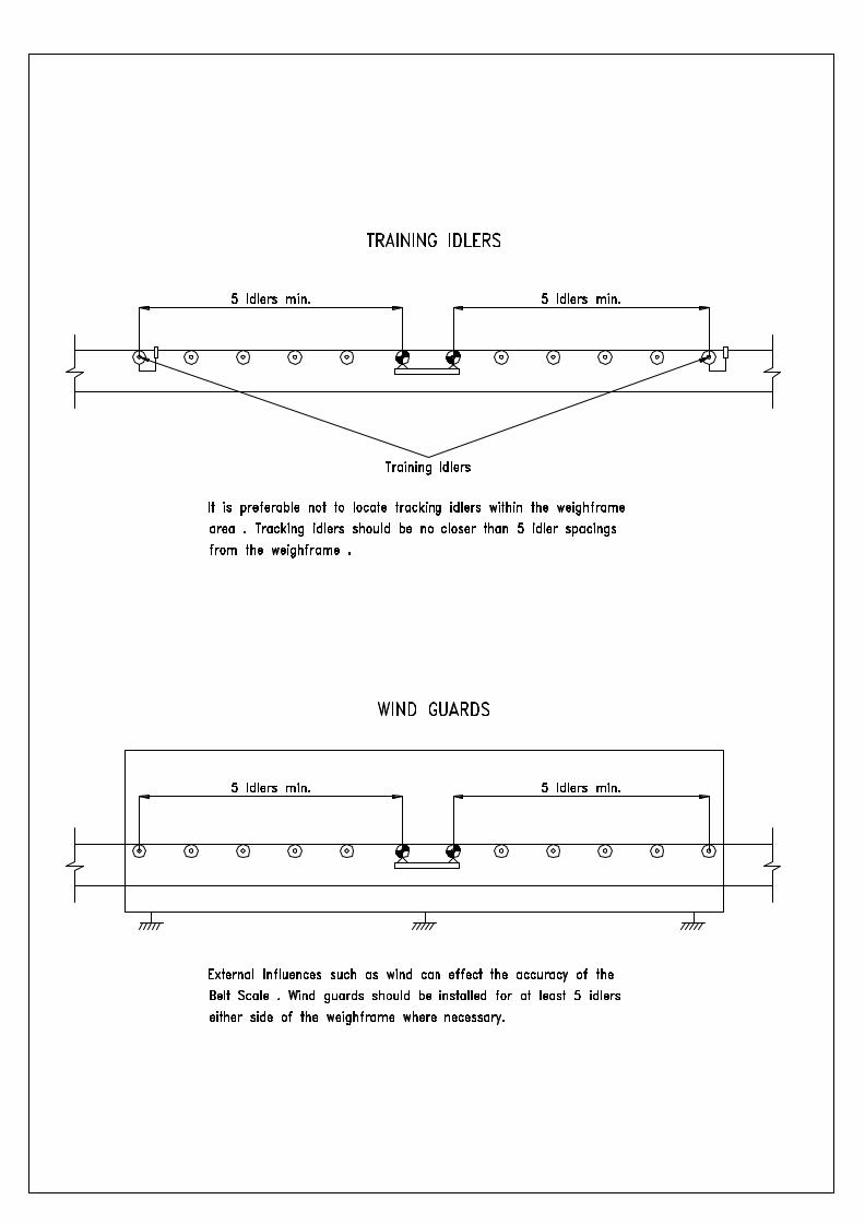
Belt Type The selected belt type should use the minimum number of plies possible. Additional plies add to the stiffness of the belt and therefore reduce the achievable accuracy. Steel cored belts are the least desirable due to the stiffness of these belts. Conveyor belts should be uniform in weight, with a minimum of splices. Metal clip fasteners should not be used. Belt Tracking Belt tracking should be central to the idlers regardless of belt loading. Training idlers should not be used any closer than 5 idler spacings from the weighframe. Conveyor Idlers It is more desirable to use idlers with shallow troughing angles. Idlers with 20º angle are better than 30º angle, and 30º is better than 35º . Idlers with 45º troughing angle can be used, however errors due to belt tension changes are more significant. The steepness of the troughing angle determines the planar moment of inertia of the belt, which determines how susceptible the Belt Scale is to belt tension variations and misalignment. Idlers on the weighframe, two approach and two retreat idlers should be: R In-Line "Weigh Quality" R Rolls should be machined concentric to provide 0.13 mm Total Indicated Runout R Rolls to be balanced within 0.011 Nm R Rolls to be fitted with some form of height adjustment On some low accuracy applications, some of the above requirements may not be required . Idler Alignment The mechanical alignment of the weigh, approach and retreat idlers is critical. The height misalignment in this area should be no greater than 0.4 mm. Mechanical misalignment of these idlers will cause the accuracy of the system to vary depending on belt tension variations. It is advisable to have the Belt Scale supplier assist in the mechanical installation Conveyor Stringers The conveyor stringers should be rigid, free from vibration and capable of supporting the load without deflection. Weighframes and approach / retreat idlers should not be installed where joins in the stringers exist If this is not possible, stringers should be welded together using "fish" plates. The stringers should be suitably supported in the area of the weighframe / approach / retreat idlers so that the total deflection within the weigh area does not exceed 0.25 mm.

BELT SCALE SELECTION AND INSTALLATION GUIDE (CONT'D)
Environmental Protection Where the conveyor is exposed to the elements, errors may be induced by external influences such as wind. Errors equivalent to 30 tonnes per hour have been measured on large conveyors subject to high wind velocities. These errors can be minimised by installing guards, which protect the weighframe and 5 metres of conveyor in each direction. Where possible, supply the Belt Scale manufacturer with a detailed arrangement drawing of the proposed installation with as many parameters as known .


BELT SCALE SELECTION AND INSTALLATION GUIDE (CONT'D)
5. WHICH MODEL BELT SCALE ? Most Belt Scale manufacturers can supply a number of different model weighframes and electronics. Some models may appear to duplicate each other in regard to accuracy specifications and general features. For example, two different model weighframes may be specified at an accuracy of +/- 0.5 %. However one model may be designed for medium duties with relatively light belt loadings and the other for heavy-duty applications with high belt loadings. When you examine the construction of the weighframe, will it stand up to the duty? The accuracy of the system will be determined by the weighframe type, as the same model electronics will normally be used regardless of the accuracy requirements. More than one model electronics may be available, however this is generally because they offer various options. When specifying a desired accuracy for the Belt Scale system, the application should be investigated thoroughly. Like most equipment, the higher the accuracy specified the more expensive the system will be. Belt Scale accuracy depends on a number of factors such as belt tension, belt type, location and belt loadings. However they are usually categorised into one of three groups. SINGLE IDLER General purpose process scales, with typical accuracies in the order of 1 % to 3 %. DUAL IDLER Inventory purpose scales with typical accuracy of 0.5 %. MULTI IDLER High precision systems such as shiploaders and scales for payment purposes. Accuracy typically 0.25 %. However in some applications it may be necessary to use a four idler weighframe to achieve 1% accuracy. On other applications, a single idler weighframe may achieve 0.5% accuracies The Belt Scale supplier will require certain information regarding the application, which should be detailed on their "Application Data" sheets. It may be preferable to allow the supplier to review the data and advise what options are available in regard to the possible accuracy versus the costs, rather than specifying the accuracy.

BELT SCALE SELECTION AND INSTALLATION GUIDE
(CONT'D)
6. ONGOING MAINTENANCE Many Belt Scale installations are ignored until a problem exists. Like all equipment a minimum of maintenance will assist in providing long-term reliability. For multiple installations at the one site it may be worth contracting the Belt Scale supplier to carry out the maintenance and regular calibrations. These visits can also be used to provide basic training for the site personnel in the event of an emergency breakdown situation. These site visits are normally scheduled at three monthly intervals. The following work should be carried out on a regular basis: R Clean down of build-up on weighframe and removal of spillage R Inspection and cleaning of idler rolls R Zero calibrations R Inspect belt tracking R Inspect belt wear The following work can be carried out less frequently: R Span calibrations R Check mechanical alignment R Balance transducers (where necessary) R Check cabling and junction boxes Apart from the general housekeeping of the installation, the other important aspect that should be addressed is the record keeping for each installation. Most modern Belt Scale electronics store all data in battery backed or non-volatile memory, however in the case of catastrophic failure this data will probably be lost or not accessible. At these times it is essential that accurate records be available for reprogramming purposes. Accurate records also allow review of the Belt Scale performance and possible problems that may require attention. Belt Scale suppliers will usually be able to provide proper data record sheets that can be used in conjunction with the maintenance program.


![Belt Selection Guide 2005 - Прогресс [eng].pdf · Modular Plastic Conveyor Belts Belt Selection Guide July 2004. ... modular plastic conveyor belt experts are available ...](https://static.fdocuments.us/doc/165x107/5a9f7dd97f8b9a71178cd2bb/belt-selection-guide-2005-engpdfmodular-plastic-conveyor-belts.jpg)


