Dräger Polytron Pulsar 2 - poweras.com.tr · Intended Use Intended Use The Dräger Polytron Pulsar...
18
Dräger Polytron Pulsar 2 Open Path Gas Detector en WARNING You must read, understand, and follow these instructions for use before you use the gas detector in order to ensure the proper operation and function of the gas detector. ! Polytron Pulsar 2 - Instuctions For Use 3 - 16
Transcript of Dräger Polytron Pulsar 2 - poweras.com.tr · Intended Use Intended Use The Dräger Polytron Pulsar...

Dräger Polytron Pulsar 2Open Path Gas Detector
en
WARNING
You must read, understand, and follow these instructions for use before you use the gas detector in order to ensure the proper operation and function of the gas detector.
!
Polytron Pulsar 2 - Instuctions For Use 3 - 16


Safety Symbols used in this Instructions For Use
Safety Symbols used in this Instructions For Use
While reading these Instructions For Use, you will come across a number of warnings concerning some of the risks and dangers you may face while using the device. These warnings contain “signal” words that will alert you to the degree of hazard you may encounter. These words, and the hazard they describe, are as follows:
DANGER
Indicates an imminently hazardous situation which, if not avoided, will result in death or serious injury.
!
WARNING
Indicates a potentially hazardous situation which, if not avoided, could result in death or serious injury.
!
CAUTION
Indicates a potentially hazardous situation which, if not avoided, could result in physical injury.
!
NOTICE
Indicates a potentially hazardous situation which, if not avoided, could result in damage to the product.
!
For Your Safety
Strictly follow these Instructions for UseAny use of the gas detector requires full understanding and strict observation of these instructions. This gas detector is only to be used for the purposes specified herein.
MaintenanceThe device must be inspected and serviced by experts at regular intervals and a record kept. Repair and general overhaul of the device may only be carried out by appropriately trained service personnel. We strongly recommend that a service contract be signed with Dräger for repairs and maintenance. Only authentic Dräger spare parts may be used for maintenance. Be sure to read the information contained in the chapter “Maintenance Intervals” of the user manual.
AccessoriesOnly use accessories listed in the order list on page 11.
Safe Connection of Electrical DevicesDo not connect electrical devices not mentioned in this manual before contacting the manufacturer or an expert.
Use in areas subject to explosion hazards Equipment or components which are used in potentially explosive-hazard areas and have been tested and approved according to national, European or international regulations may only be used under the specified conditions under which they were approved. The equipment or components may not be modified in any manner.

Intended Use
Intended Use
The Dräger Polytron Pulsar 2 Open Path Gas Detector is intended for stationary, continuous monitoring of hydrocarbon gases or vapours that may present and explosion hazard.
Explosion protection approvalsThe explosion-protection approvals are valid for use of the device in gas/vapour-air mixture of combustible gases and vapours under atmospheric conditions. The explosion-protection approvals are not valid for use in oxygen enriched atmospheres. In case of unauthorized opening of the enclosure, the explosion-protection approval is voided.
NOTE: The Dräger Polytron Pulsar 2 Open path Gas Detector is one of the family of detectors certified under the designation GD8. All certificates will refer to the GD8.
Parts Supplied1. The Dräger Polytron Pulsar 2 Open Path Gas Detector comes in two parts,
a transmitter and a receiver; each supplied with an ABS moulded cover. Additionally the detector is supplied with either:
— Flying leads and Ex e junction boxes.— Ex d certified plugs and sockets.
2. An optical attenuator for use on beam paths between 4 and 16 meters, NOTE this is only supplied with 4-60m transmitters.
3. An installation sheet and a quick start guide are supplied with the detector. Installation/operation manuals are also available through local distributors or by contacting Dräger UK Ltd.
4. You will also require a commissioning kit which is ordered separately and includes:
— Hand Held terminal (HHT)— 4mm Allen key— Test Sheets— HHT PC software— PC Cable
Installing
Only trained service personnel (e.g. Dräger service personnel) may install the gas detector under observation of the regulations applicable at the respective location.
Choosing the path of the beam and Mechanical Installation1. The siting of an open path gas detector is often not as critical as a point
detector, since the released gas only has to find its way into some portion of the beam instead of to a particular point. However, siting is still an important consideration. Guidance for siting is contained in EN 60079-29-2.
2. Dräger Polytron Pulsar 2 Open Path Gas Detector is immune to sunlight so there is no need to take account of the sun position when siting detectors.
3. The density of the gas to be detected has to be considered. Methane is lighter than air and may be expected to rise, unless released at a low temperature or in a mixture with a heavier gas like carbon dioxide. Likewise, heavier hydrocarbons may be expected to fall. However such simple considerations as buoyancy may not be a reliable indicator of gas movement in practical situations. Gas leaking from high-pressure systems entrains with it a much larger volume of ambient air, forming a mixture that may be flammable and almost neutrally buoyant. In these circumstances, it is the natural air currents or forced ventilation that control the motion of the plume or cloud. Where air movements are unpredictable it may be necessary to use separate beam paths to cover different possibilities.
4. The distance between the transmitter and receiver should agree with the model selected (i.e. 4-60m, 30-120m or 100-200m). Note that the optical attenuator should be fitted below 16 metres.
5. The beam path and immediate surround should be kept free of obstructions that might hinder the free movement of air in the protected area or block the infrared beam. A clear path of 25cm diameter or greater is recommended. For maximum availability it is also recommended to avoid the following:
— Smoke stacks, chimneys and exhausts.— Steam vents and plumes.

Installing
— Walkways and areas where personnel muster or collect.— Splash and spray from moving equipment and cooling towers etc.— Parking, loading, cranes, vehicle temporary stops.— Vegetation that may grow tall enough to impinge on the path especially with movement by the wind.— Surfaces that may obstruct the beam path with a build up of ice or snow.
CAUTION
On no account should you attempt to open the housing of the Gas Detector! The device does not contain any parts that can be serviced by the user.
!
Mounting the unitThe Dräger Polytron Pulsar 2 Open Path Gas Detector should be mounted to a stable structure free of excessive vibration. Good choices would be a steel bulkhead, brick wall, concrete post or a rigid steel structure. Avoid flimsy metal structures that may flex, or wooden structures that may warp. In open areas a suitable structure close to the ground would consist of a five inch nominal (141mm outside diameter) steel pipe driven 1 metre into firm ground or embedded into a concrete foundation. Tall structures should be suitably guyed or braced.
Figure 1: Wall mounting of Dräger Polytron Pulsar 2 Open Path Gas Detec-tor with Ex e junction box
Figure 2: Wall mounting of Dräger Polytron Pulsar 2 Open Path Gas Detec-tor eX link plug and socket

Installing
Figure 3: Connection powered via transmitter
Figure 4: Connection powered via receiver
1
1
2
2
3
3
4
4
5
5
6
6
7
7
S
S
E
E
1
1
2
2
3
3
4
4
5
5
6
6
7
7
S
S
E
E
DR
AW
ING
NO
- G
D8 5
9
TIT
LE
- C
onnect
ion D
iagra
m E
x e T
erm
inal B
ox
(OP
TIO
N 2
- p
ow
ere
d v
ia R
ece
iver
)
PR
OD
UC
T-
GD
8IS
SU
E N
O-
1.6
2
4/1
1/2
011
Not fo
r m
anufa
cture
RE
VIS
ED
BY
- K
eith
Chitt
y
CH
EC
KE
D B
Y-
CH
EC
KE
D B
Y-
DA
TE
-
DA
TE
-
DR
AW
N B
Y -
Paul M
ars
h
Ply
mouth
UK
Dra
eger
PL
MS
Ltd
.C
Installing
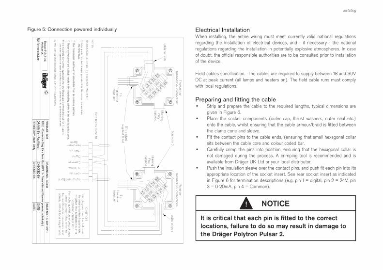
Figure 5: Connection powered individually
Electrical InstallationWhen installing, the entire wiring must meet currently valid national regulations regarding the installation of electrical devices, and - if necessary - the national regulations regarding the installation in potentially explosive atmospheres. In case of doubt, the official responsible authorities are to be consulted prior to installation of the device.
Field cables specification. -The cables are required to supply between 18 and 30V DC at peak current (all lamps and heaters on). The field cable runs must comply with local regulations.
Preparing and fitting the cable• Strip and prepare the cable to the required lengths, typical dimensions are
given in Figure 6.• Place the socket components (outer cap, thrust washers, outer seal etc.)
onto the cable, whilst ensuring that the cable armour/braid is fitted between the clamp cone and sleeve.
• Fit the contact pins to the cable ends, (ensuring that small hexagonal collar sits between the cable core and colour coded bar.
• Carefully crimp the pins into position, ensuring that the hexagonal collar is not damaged during the process. A crimping tool is recommended and is available from Dräger UK Ltd or your local distributor.
• Push the insulation sleeve over the contact pins, and push fit each pin into its appropriate location of the socket insert. See rear socket insert as indicated in Figure 6 for termination descriptions (e.g. pin 1 = digital, pin 2 = 24V, pin 3 = 0-20mA, pin 4 = Common).
NOTICE
It is critical that each pin is fitted to the correct locations, failure to do so may result in damage to
the Dräger Polytron Pulsar 2.
!

Installing
Figure 6: Cable Preparation and Wiring
The socket insert is now ready to be inserted into the socket sleeve. Ensure that the large contact pin (4) is in the 8 o’clock position in relation to the location lug (as indicated in fig. 6 front of eXLink socket). Carefully push the socket insert into the sleeve and ensure that the location lug secures correctly. When fully fitted, the insert should protrude by approximately 13mm and although there is a little movement when attempting to turn the socket insert, it should not rotate. If the insert does rotate then it is not fitted correctly and requires adjustment to secure it into position. Finally secure the remaining components of the socket before tightening the outer cap nut.
Connecting the plug and socketEnsuring that the key way is in the correct position, push the socket into the plug. Turn the connector to the right by approximately 30° and then fully insert before screwing the coupling of the socket to the plug in order to establish the IP protection and mechanical protection. Reverse this process in order to disconnect the plug and socket.
Figure 7: Connection powered individually using CEAG Ex d Connector
Commissioning
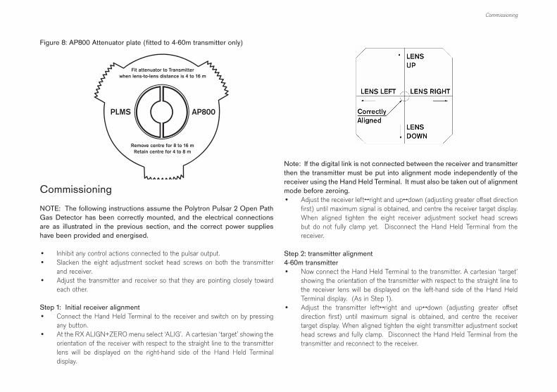
Note: If the digital link is not connected between the receiver and transmitter then the transmitter must be put into alignment mode independently of the receiver using the Hand Held Terminal. It must also be taken out of alignment mode before zeroing.• Adjust the receiver left↔right and up↔down (adjusting greater offset direction
first) until maximum signal is obtained, and centre the receiver target display. When aligned tighten the eight receiver adjustment socket head screws but do not fully clamp yet. Disconnect the Hand Held Terminal from the receiver.
Step 2: transmitter alignment4-60m transmitter• Now connect the Hand Held Terminal to the transmitter. A cartesian ‘target’
showing the orientation of the transmitter with respect to the straight line to the receiver lens will be displayed on the left-hand side of the Hand Held Terminal display. (As in Step 1).
• Adjust the transmitter left↔right and up↔down (adjusting greater offset direction first) until maximum signal is obtained, and centre the receiver target display. When aligned tighten the eight transmitter adjustment socket head screws and fully clamp. Disconnect the Hand Held Terminal from the transmitter and reconnect to the receiver.
Figure 8: AP800 Attenuator plate (fitted to 4-60m transmitter only)
Fit attenuator to Transmitterwhen lens-to-lens distance is 4 to 16 m
AP800PLMS
Remove centre for 8 to 16 mRetain centre for 4 to 8 m
Commissioning
NOTE: The following instructions assume the Polytron Pulsar 2 Open Path Gas Detector has been correctly mounted, and the electrical connections are as illustrated in the previous section, and the correct power supplies have been provided and energised.
• Inhibit any control actions connected to the pulsar output.• Slacken the eight adjustment socket head screws on both the transmitter
and receiver.• Adjust the transmitter and receiver so that they are pointing closely toward
each other.
Step 1: Initial receiver alignment• Connect the Hand Held Terminal to the receiver and switch on by pressing
any button.• At the RX ALIGN+ZERO menu select ‘ALIG’. A cartesian ‘target’ showing the
orientation of the receiver with respect to the straight line to the transmitter lens will be displayed on the right-hand side of the Hand Held Terminal display.

Commissioning
30 to 120m and 100 to 200m transmitters• Connect the Hand Held Terminal and check that the signals from the receiver
are being displayed. If they were absent it would indicate that the digital link from the receiver was not connected, usually due to a wiring fault. Also look into the transmitter lens to check it is flashing at the correct, irregular rate of four per second. A regular twice per second would indicate inadequate voltage at the supply or excessive voltage drop in the supply cables.
• At the left of the alignment screen the transmitter ‘target’ indicates the degree of misalignment but not (unlike the receiver) its direction:
• First move the transmitter around to be sure you have found the strong central peak in signal. Make slow adjustments, first vertically then horizontally, to maximise the signal strength. The final horizontal adjustment moves the circle from right to left, until the display matches the diagram. Tighten the eight screws progressively in rotation to avoid losing the alignment. The transmitter and connector covers can now be replaced.
Step 3: Final receiver alignment• Check the receiver target display is correct. Both transmitter and receiver
displays should now be centred. If not repeat steps 1 and 2. If correct fully tighten the eight receiver socket head screws.
Step 4: The zeroing procedure• Press any key to enter RX ALIGN + ZERO menu, then select ‘ZERO’. A
message is displayed: ‘SAFETY WARNING’ Are you sure beam path is free of gas?
• If you are sure there is no gas present select ‘YES’ otherwise press any other key to abort zero. Once ‘YES’ is pressed the Hand Held Terminal will display a count down from 32 to 1. (At the same time the analogue output will increase to 20mA and ramp down to 4mA).
• Observe the Hand Held Terminal display until ‘ZEROING DONE’ is displayed at the bottom of the screen.
• Turn off the Hand Held Terminal by pressing any two buttons together and disconnect.
WARNING
If the control equipment fails to indicate 100%LEL at the start of the zeroing procedure it indicates that the resistance in the 4-20 mA current-loop is
too high. It is essential to investigate such a fault,
which could cause under-reading of gas.
!
Step 5: Verification with test sheets• Hold a stack of five immediately in front of the receiver lens. Verify from
the Hand-Held Terminal screen and from the control equipment that the complete system responds correctly, as if to gas.
• If the reading is off scale, remove sheets one by one until it is on scale. • Record the mean reading, together with the serial numbers of the transmitter,
receiver and test sheets for future reference.
Recording the test sheet readings enables you to check subsequently that the response to gas has not been affected in any way. You may also wish to introduce the test sheets one by one to check correct operation of the control equipment at intermediate readings. If required, similar checks can be carried out with real gas using the Gas Check Kit GCK400.

Normal Operation
A Polytron Pulsar 2 Open Path Gas Detector should always be re-zeroed whenever it is re-sited, cleaned or re-aligned.
Normal Operation
The Dräger Polytron Pulsar 2 Open Path Gas Detector generates a 4-20mA signal, proportional to the measured gas concentration, when the device configured for analogue signal transmission. It can also be configured for digital transmission through the use of HART.
Current Meaning
20.5 mA Over-range
4-20 mA Measuring
3.5 mA Pre-warning (dirty optics or mis-alignment)
2 mA Beam Block
<1 mA Fault
NOTE: A sudden release of a large amount of pressurised and/or refrigerated gas can result in a loss of visibility caused by condensation of atmospheric water or the released gas itself. As true for all optical open path systems, this may induce a beam block on the Dräger Polytron Pulsar Open Path Gas Detector which will impair detector’s ability to detect the gas. The beam block warning would be activated and reported to the user. Although the scenario is rather unlikely, choosing shorter rather than longer path lengths when installing Pulsars in this application can further reduce occurrence. In environments where fog generated by gas leaks is a frequent problem, beam blocks should be taken as indication for potential hazards and the use of additional point detectors should be considered.
Other configurable settings in the Receiver, (such as the quantity of gas for full-scale in the 4-20mA current loop, baseline deadband or auto zero tracking - AZT), are less frequently changed and are often the same for all Dräger Polytron Pulsars at the same site. The current values active in the Receiver can be read by selecting SETS in ‘Rx Main Menu’. A new configuration file can be written from the Hand Held Terminal with USER in ‘Rx Memory Menu’. To see the settings that are available to be sent, choose SETS in the ‘Not Connected’ menu. To change them, connect the Dräger Hand Held Terminal to a computer in the non-hazardous area, go to PC in the ‘Not Connected’ menu, and run the Dräger software supplied.
AZT automatically cancels small deviations of gas reading that persist for a long time. The rate is set in units of LEL.m/h. Baseline Dead-Band is the threshold of gas readings that cause the analogue output to rise above either 4mA or the Warning Current. AZT and baseline deadband settings should be chosen while considering the ambient condition at the point of installation. In particular in harsh outdoor environments where a slow increase of gas is not possible, higher AZT and baseline deadband settings can be chosen. In indoor applications where small leaks could lead to a slow increase of gas concentrations, AZT and baseline deadband values must be kept at a low level.
NOTE:The Dräger Polytron Pulsar is supplied with default configurations as listed in the Specifications section of the Technical Manual. Any changes to these default settings are carried out as part of the commissioning process.
Receiver AZT and Dead-Band default settings:
Auto Zero Tracking rate range: 0 - 12 LFLm per hour default: 0.05* LFLm per hour
Dead-Band range: 0 - 0.5 default: LFLm 0.3** LFLm
*AZT default values or lower comply with EN 60079-29-4:2009 and the requirements of the DNV marine approval (DNV except duct mount IFU).Note: Default AZT settings on older Pulsars. This should be taken into account when replacing older units in harsh environments.** Default values or lower comply with EN 60079-29-4:2009 and the requirements of the DNV marine approval (DNV except duct mount IFU).Note: Default deadband settings on older Pulsars. This should be taken into account when replacing older units in harsh environments.

Accessories
Accessories
The following accessories are offered for the Dräger Polytron Pulsar 2 Open Path Gas Detector.
Part Number Dräger Polytron Pulsar 2 Accessories
2350298 Junction Box Dräger Polytron Pulsar 2 ATEX
2350306 AI500 Digital Interface Unit for Dräger Polytron Pulsar 2
2350325 Dräger Polytron Pulsar 2 Alignment Kit, ATEX/CSA
2350326 Adapter AI500 to HHT or PC
2350327 Dräger Polytron Pulsar 2 PC Software with cable (supports Pulsar, AI500 and HHT)
2350238 Data Wand for AI500
2350339 Attenuator plate AP800
2350322 Dräger Polytron Pulsar 2 Remote Junction Box/HHT Kit
2350505 Dräger Polytron Pulsar 2 Alignment Telescope
2350510 ABS Moulded Cover
2350518 Gas Cell Kit single pass - Methane and Propane
2350521 Gas Test Sheets (set of 5, spares for p/n 2350325)
The Hand Held Terminal
The Dräger Ltd Hand Held Terminal is a robust and weatherproof unit, certified for use in hazardous areas. It replaces the MTL611B Communicator (based on a Psion Organiser) that was formerly supplied. The Hand Held Terminal is used to align and zero the Dräger Polytron Pulsar 2 transmitter and receiver and to provide basic configuration and diagnostic functions. Comprehensive configuration and diagnostics are also provided in conjunction with a personal computer located in the non-hazardous area. Thus a new configuration file can be loaded into an internal memory from the PC, and then copied into one or more Dräger Polytron Pulsar 2 Open Path Gas Detectors located in the hazardous area. Similarly, the unit can store the internal data-logger records of up to three Dräger Polytron Pulsar 2 Open Path Gas Detectors, and then transfer the files to the PC for analysis or transmission.
Figure 9: Hand Held Terminal (HHT)
Dräger Polytron Pulsar 2 Digital Interface AI500
Dräger Polytron Pulsar 2 Digital Interface AI500
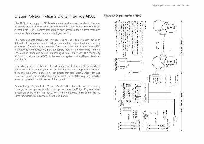
The AI500 is a compact DIN/EN rail-mounted unit, normally located in the non-hazardous area. It communicates digitally with one to four Dräger Polytron Pulsar 2 Open Path Gas Detectors and provides easy access to their current measured values, configurations, and internal data-logger records.
The measurements include not only gas reading and signal strength, but such detailed information as supply voltage, temperature, noise level and the x y alignments of transmitter and receiver. Data is available through a hard-wired EIA RS 422/485 communications port, a separate port for the Hand-Held Terminal (or Communicator), and has an infra-red signal to a Data Wand. This multiplicity of functions allows the AI500 to be used in systems with different levels of complexity.
In a fully-engineered installation the full current and historical data are available continuously to a central system via an EIA RS 485 multi-drop. In the simplest form, only the 4-20mA signal from each Dräger Polytron Pulsar 2 Open Path Gas Detector is used for indication and control action, with states requiring operator attention signalled as static values of the current.
When a Dräger Polytron Pulsar 2 Open Path Gas Detector is identified as requiring investigation, the operator is able to call up any one of the Dräger Polytron Pulsar 2 receivers connected to the AI500. Where the Hand Held Terminal and has the same functionality as if connected to the field units
Figure 10: Digital Interface AI500

Dräger Polytron Pulsar 2 Open Path Gas Detector with HART
Dräger Polytron Pulsar 2 Open Path Gas Detector with HART
The HART enhanced Dräger Polytron Pulsar 2 Open Path Gas Detector allows basic digital communications between the receiver in the field and the safe area without the need for extra cable cores. The digital signals are overlaid on the 0-20mA analogue current as a symmetrical modulation, ensuring that the integrity of the normal reading remains unaffected. The Dräger Polytron Pulsar 2 Open Path Gas Detector is fully compatible with Version 5 standards for a slave device published by the Hart Communication Foundation (HCF). Thus Dräger Polytron Pulsar 2 Open Path Gas Detector inputs to a multiplexer can be mixed with those from any other HART-compatible device, including Dräger point detectors.
Figure 11: Typical Hart Installation
PC running Emerson AMS Software
RS232 / RS485 Converter
RS485 multidrop (max 31 x MTL4841)
1
32
Normal 0-20mA outputs to control equipment
HART multiplexor MTL4841 + 2 x MTL4842 (max)
0-20mA analogue current loops with
HART digital signals
1
32
Pulsar Receivers or other HART devices 1 to 32 (max 256)
Maintenance
Observe EN 60079-29-2 and respective national regulations.
WARNING
The Dräger Polytron Pulsar 2 Open Path Gas Detector contains no user serviceable components. In the event of suspected failure of the transmitter or receiver, the suspect unit should be returned to Dräger UK Ltd.
NO ATTEMPT SHOULD BE MADE TO DIS-ASSEMBLE THE UNITS IN THE HAZARDOUS AREA!
!
1. The Dräger Polytron Pulsar 2 Open Path Gas Detector has been designed so that it will give long and reliable service with the minimum of maintenance. The Dräger Polytron Pulsar 2 Open Path Gas Detector will warn the operator if the optics becomes contaminated or if it becomes misaligned for any reason.
2. Depending on the application and the environment as well as the work practices at the site planned maintenance consists of-
• Checking the detectors response to Gas Check Cards. Ensuring firstly that any control functions have been inhibited.
• Cleaning of the optics as necessary. If the detector warns of contaminated optics or if it is known that the detector may have been contaminated by drilling mud, oil mist, dust etc. The lenses are specially coated to assist in keeping them clean, however if it becomes necessary to clean them care must be taken so as not to remove the lens coating. A soft cloth with clean fresh water or Dräger UK Ltd lens cleaning fluid should be used. The detector should be realigned and re-zeroed as per the instructions following any work on the detector.

Calibration
Calibration
Unlike conventional detectors Dräger Polytron Pulsar 2 Open Path Gas Detector’s built-in calibrations need no manual adjustment, but a self-zeroing sequence is initiated by the Hand Held Terminal to complete the commissioning of the detector. (See Set-up and Commissioning)
Fault – Cause – Remedy
Fault and warning messages: see Technical Manual, section “Faults, Cause, and Remedy”.
Safety Integrity Level
The Dräger Polytron Pulsar 2 Open Path Gas Detector is suitable for use in SIL 2 applications.
NOTICE
For applications with Safety Integrity Level (SIL) and any other configuration (when applicable),
observe the Technical Manual.
!
How to Dispose of the Device
From August 2005, regulations apply to the whole of the EU for the disposal of electrical and electronic devices; these regulations are set in the EU Directive 2002/96/EG and in national laws relating to this device.
Special collection and recycling possibilities have been established for private households. However, since the device has not been registered for use in private households, it cannot be disposed of as special household waste. For disposal, it can be sent back to your national Dräger UK Sales organisation; if you have any questions requiring disposal, then please contact this location.
Technical Data
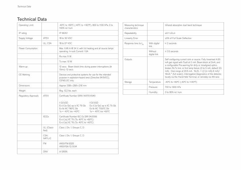
Technical DataOperating Limit: -40°C to +60°C (-40°C to +140°F), 800 to 1100 hPa, 0 to
100% rel. hum
IP rating IP 66/67
Supply Voltage ATEX 18 to 30 VDC
UL, CSA 18 to 27 VDC
Power Consumption Max. 0.95 A @ 24 V, with full heating and all source lamps operating. In-rush Current: 1.5A
Rx max: 5 W
Tx max: 13 W
Warm-up: 12 secs. Beam block time during power interruptions (≥ 10ms): 12 secs.
CE Marking Devices and protective systems for use for the intended purpose in explosion-hazard area (Directive 94/9/EC), CENELEC only
Dimensions Approx: 338 x 258 x 216 mm
Weight 6kg, 12,2 lbs, each
Regulatory Approvals ATEX Certificate Number SIRA 14ATEX1040
II 2(1)GDEx d [ia Ga] op is IIC T6 GbEx tb IIIC T80°C DbTa = -40°C bis +40°C
II 2(1)GDEx d [ia Ga] op is IIC T5 GbEx tb IIIC T100°C DbTa = -40°C bis +60°C
IECEx Certificate Number IEC Ex SIR 04.0006 Ex d [ia] IIC T5 (Ta -40°C to +60°C) Ex d [ia] IIC T6 (Ta -40°C to +40°C)
UL (Classi-fied)
Class I, Div. 1, Groups C, D
CSA, NRTL/C
Class I, Div. 1, Groups C, D
FM ANSI/FM 6325ANSI/ISA-12.13.04
DNV A-12526
Measuring technique characteristics
Infrared absorption dual band technique
Repeatability ±0.1 LELm
Linearity Error ±5% of Full Scale Deflection
Response time to t90
With digital link
≤ 2 seconds
Without digital link
≤ 2.5 seconds
Outputs Self configuring current sink or source. Fully linearised 4-20 mA gas signal with Fault at 0 mA, Beam-block at 2mA, and a configurable Pre-warning for dirty or misaligned optics, broken Rx-Tx link, or first lamp failure (0 to 5 mA, default 3.5 mA). Over-range at 20.5 mA. %LEL = ((I (in mA)-4 mA)/ 16mA * (full scale)). Interrogation/diagnostics of the detector, locally via the Hand-Held Terminal, or remotely via 4th-wire
Storage Temperature: -40°C to +60°C (-40°C to +140°F)
Pressure: 700 to 1300 hPa
Humidity: 0 to 95% rel. hum


Manufactured by Dräger UK LimitedUllswater CloseBlyth Riverside Business ParkBlyth, NorthumberlandNE24 4RG, United Kingdom
Tel: +44 1670 352 891Fax: +44 1670 544 475
www.draeger.com
Dräger Safety AG & Co. KGaARevalstraße 123560 Lübeck, Germany
Tel +49 451 882 0Fax +49 451 882 20 80
www.draeger.com
2309805© Dräger UK LtdEdition 05 – October 2016Subject to alteration