DIVISION II CONSTRUCTION AND MATERIAL … · DIVISION II CONSTRUCTION AND MATERIAL SPECIFICATIONS...
95
DIVISION II CONSTRUCTION AND MATERIAL SPECIFICATIONS SECTION 2200 PAVING Approved and Adopted this 23rd day of May, 2001 Amended June 4, 2015 by Ordinance 150411 KANSAS CITY METROPOLITAN CHAPTER OF THE AMERICAN PUBLIC WORKS ASSOCIATION SECTION 2201 SUBGRADE PREPARATION............................................................ 1 2201.1 Summary .............................................................................................. .............. 1 2201.2 Definitions........................................................................................................... 1 2201.3 Construction......................................................................................... ............... 1 2201.4 Methods of Measurement..................................................................... .............. 2 2201.5 Basis of Payment................................................................................................. 2 SECTION 2202 UNTREATED COMPACTED AGGREGATE.................................. 3 2202.1 Summary .............................................................................................. .............. 3 2202.2 Material ................................................................................................ .............. 3 2202.3 Placement ............................................................................................. .............. 4 2202.4 Methods of Measurement..................................................................... .............. 4 2202.5 Basis of Payment................................................................................................. 5 SECTION 2203 DRAINABLE BASE COURSE.............................................................6 2203.1 Summary .............................................................................................. .............. 7 2203.2 Materials............................................................................................... .............. 7 2203.3 Crushed Aggregate Base Course.......................................................... .............. 7 2203.4 Portland Cement Concrete Drainable Base......................................................... 8 2203.5 Plant Mix Bituminous Drainable Base Course .................................. .............. 10 2203.6 Underdrains........................................................................................ ............... 14 2203.7 Permeability Test Procedure.............................................................. ............... 17 2203.8 Methods of Measurement................................................................... .............. 21 2203.9 Basis of Payment............................................................................................... 21 SECTION 2204 PRIME AND TACK COAT.............................................................. . 23 2204.1 Summary............................................................................................ ............... 23 2204.2 Liquid Asphalt Material ..................................................................... .............. 24 2204.3 Sand Cover......................................................................................... ............... 24 2204.4 Approval of Materials ........................................................................ .............. 24 2204.5 Pressure Distributor............................................................................ .............. 24 2204.6 Preparation of Existing Surface ......................................................... .............. 24 2204.7 Application of Asphalt Material......................................................... .............. 24 2204.8 Application of Sand Cover................................................................................ 25 2204.9 Methods of Measurement................................................................... .............. 25 2204.10 Basis of Payment............................................................................................... 25
Transcript of DIVISION II CONSTRUCTION AND MATERIAL … · DIVISION II CONSTRUCTION AND MATERIAL SPECIFICATIONS...

DIVISION II
CONSTRUCTION AND MATERIAL SPECIFICATIONS
SECTION 2200 PAVING
Approved and Adopted this 23rd day of May, 2001
Amended June 4, 2015 by Ordinance 150411
KANSAS CITY METROPOLITAN CHAPTER
OF THE AMERICAN PUBLIC WORKS ASSOCIATION
SECTION 2201 SUBGRADE PREPARATION............................................................ 1
2201.1 Summary .............................................................................................. .............. 1
2201.2 Definitions........................................................................................................... 1
2201.3 Construction......................................................................................... ............... 1
2201.4 Methods of Measurement..................................................................... .............. 2
2201.5 Basis of Payment................................................................................................. 2
SECTION 2202 UNTREATED COMPACTED AGGREGATE.................................. 3
2202.1 Summary .............................................................................................. .............. 3
2202.2 Material ................................................................................................ .............. 3
2202.3 Placement ............................................................................................. .............. 4
2202.4 Methods of Measurement..................................................................... .............. 4
2202.5 Basis of Payment................................................................................................. 5
SECTION 2203 DRAINABLE BASE COURSE.............................................................6
2203.1 Summary .............................................................................................. .............. 7
2203.2 Materials............................................................................................... .............. 7
2203.3 Crushed Aggregate Base Course.......................................................... .............. 7
2203.4 Portland Cement Concrete Drainable Base......................................................... 8
2203.5 Plant Mix Bituminous Drainable Base Course .................................. .............. 10
2203.6 Underdrains........................................................................................ ............... 14
2203.7 Permeability Test Procedure.............................................................. ............... 17
2203.8 Methods of Measurement................................................................... .............. 21
2203.9 Basis of Payment............................................................................................... 21
SECTION 2204 PRIME AND TACK COAT.............................................................. . 23
2204.1 Summary............................................................................................ ............... 23
2204.2 Liquid Asphalt Material ..................................................................... .............. 24
2204.3 Sand Cover......................................................................................... ............... 24
2204.4 Approval of Materials ........................................................................ .............. 24
2204.5 Pressure Distributor............................................................................ .............. 24
2204.6 Preparation of Existing Surface ......................................................... .............. 24
2204.7 Application of Asphalt Material......................................................... .............. 24
2204.8 Application of Sand Cover................................................................................ 25
2204.9 Methods of Measurement................................................................... .............. 25
2204.10 Basis of Payment............................................................................................... 25

SECTION 2205 ASPHALTIC CONCRETE SURFACE AND BASE...................... . 26
2205.1 Summary............................................................................................ ............... 27
2205.2 Materials ........................................................................................................... 27
2205.3 Mixing and Proportioning............................................................... .................. 28
2205.4 Asphalt Mixing Plant ......................................................................... .............. 36
2205.5 Transportation of Mix ....................................................................................... 36
2205.6 Scales and Weighing of Vehicles....................................................... .............. 36
2205.7 Requirements for Asphalt Paving Equipment................................... ............... 37
2205.8 Construction Requirements................................................................ ............... 40
2205.9 Method of Measurement.................................................................... ............... 46
2205.10 Basis of Payment............................................................................................... 46
SECTION 2206 ASPHALT CRACK SEALING, CHIP SEALING, SLURRY
SEALING, AND MICROSURFACING ....................................................................... 47
2206.1 Summary............................................................................................ ............... 47
2206.2 Crack Sealing ..................................................................................... .............. 47
2206.3 Improved Street Chip Seal ................................................................ ............... 52
2206.4 Unimproved Street Chip Seal......................................................... .................. 55
2206.5 Improved Street Slurry Seal ............................................................... .............. 57
2206.6 Improved Street Micro-Surfacing .................................................................... 61
2206.7 Method of Measurement ................................................................................... 65
2206.8 Basis of Payment .............................................................................................. 65
SECTION 2207 COLD MILLING................................................................................ 67
2207.1 Summary............................................................................................ ............... 67
2207.2 Equipment .......................................................................................... .............. 67
2207.3 Construction Details ......................................................................................... 67
2207.4 Method of measurement..................................................................... .............. 68
2207.5 Basis of payment ............................................................................... ............... 68
SECTION 2208 PORTLAND CEMENT CONCRETE PAVEMENT....................... 69
2208.0 General ............................................................................................................. 69
2208.1 Summary............................................................................................ ............... 69
2208.2 Materials ........................................................................................................... 69
2208.3 Construction Details.......................................................................................... 72
2208.4 Joints ................................................................................................................. 73
2208.5 Placing, Finishing, Curing, and Protection ....................................................... 75
2208.6 Backfill............................................................................................... ............... 80
2208.7 Joint Sealing and Cleanup.................................................................. ............... 80
2208.8 Integral Curb .................................................................................................... 80
2208.9 Pavement Smoothness and Surface Defects: ..................................... .............. 80
2208.10 Repairing Defects ............................................................................................. 80
2208.11 Methods of Measurement................................................................... .............. 81
2208.12 Basis of Payment............................................................................................... 81
SECTION 2209 CURBING ............................................................................................ 82
2209.0 General ............................................................................................................. 82
2209.1 Summary............................................................................................ ............... 82
2209.2 Materials .......................................................................................................... 82
2209.3 Construction Details ........................................................................................ 82
2209.4 Joints ................................................................................................................ 84
2209.5 Concrete Work ................................................................................................ 85
2209.6 Backfill............................................................................................. ................. 85
2209.7 Joint Sealing and Clean-Up ............................................................................ 86
2209.8 Surface Tolerances ........................................................................... ................ 86
2209.9 Method of Measurement .................................................................. ................ 86
2209.10 Basis of Payment.............................................................................. ................ 86
SECTION 2210 MEASUREMENTS AND PAYMENTS ........................................... 87
2210.0 General ............................................................................................................. 87
2210.1 Summary .......................................................................................... ................ 87
2210.2 General ............................................................................................. ................ 87
2210.3 Measurement.................................................................................... ................. 87
2210.4 Items not listed in the Proposal........................................................ ................. 87
2210.5 Measurement and Payment Summary Table.................................... ................ 88
SECTION 2211 SMOOTHNESS......... .......................................................................... 89
2211.1 Summary .......................................................................................... ................ 89
2211.2 Local Streets & Residential Collectors............................................ ................. 89
2211.3 Arterials and Urban Collectors ....................................................................... 89
SECTION 2212 FLY ASH CONCRETE ........................................................................ 90
2212.1 Scope ............................................................................................................... 90
2212.2 General............................................ ................................................................. 90
2212.3 Fly Ash Concrete and Quality ......................................................................... 90
2212.4 Pre-qualification Procedures for Class C Fly Ash ......................................... 91
2212.5 Mix Design Requirements and Prequalification Tests ................................... 92
2212.6 Ready Mix Plant Requirements ....................................................................... 92
2201 2201.3
SECTION 2201 SUBGRADE PREPARATION
Referenced Standards: The following standards are referenced directly in this section.
The latest version of these standards shall be used.
ASTM
D 698 - Test Method for Laboratory Compaction Characteristics of Soil Using
Standard Effort (12,400 ft-lbf/ft3 (600 kN-m/m3))
2201.1 Summary: This section includes subgrade preparation at locations which have
been previously graded in accordance with the requirements of Section 2100 entitled
"Grading and Site Preparation". All materials and placement shall be tested as outlined in
the “Public Works Department Materials Testing Requirements”.
2201.2 Definitions:
A. Subgrade: Subgrade is defined as a well graded and compacted layer on which base
and subsequent courses are placed.
B. Subgrade Preparation: Subgrade preparation is the repeated operation of fine-
grading and compacting the subgrade until the specified lines, grades, and cross-
section, as indicated on the plans are obtained and the materials are compacted to the
specified depth and density.
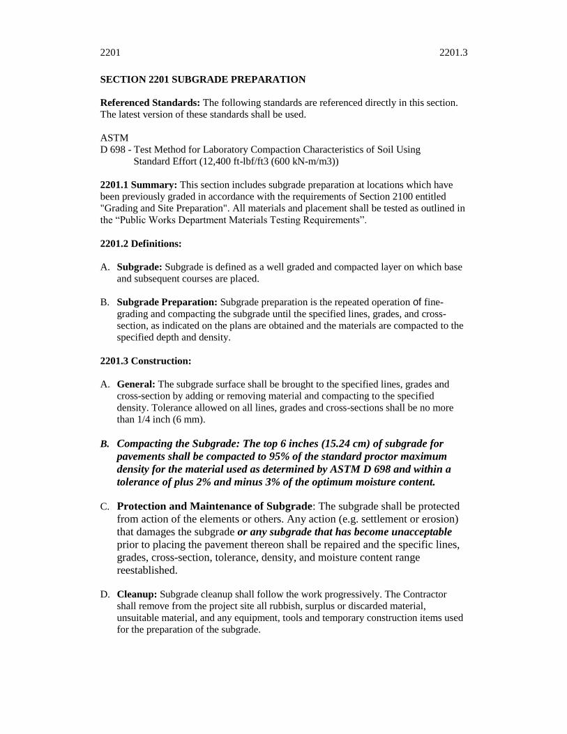
2201.3 Construction:
A. General: The subgrade surface shall be brought to the specified lines, grades and
cross-section by adding or removing material and compacting to the specified
density. Tolerance allowed on all lines, grades and cross-sections shall be no more
than 1/4 inch (6 mm).
B. Compacting the Subgrade: The top 6 inches (15.24 cm) of subgrade for
pavements shall be compacted to 95% of the standard proctor maximum
density for the material used as determined by ASTM D 698 and within a
tolerance of plus 2% and minus 3% of the optimum moisture content.
C. Protection and Maintenance of Subgrade: The subgrade shall be protected
from action of the elements or others. Any action (e.g. settlement or erosion)
that damages the subgrade or any subgrade that has become unacceptable
prior to placing the pavement thereon shall be repaired and the specific lines,
grades, cross-section, tolerance, density, and moisture content range
reestablished.
D. Cleanup: Subgrade cleanup shall follow the work progressively. The Contractor
shall remove from the project site all rubbish, surplus or discarded material,
unsuitable material, and any equipment, tools and temporary construction items used
for the preparation of the subgrade.

2201.3 2201.5
22-2
E. Roll Testing: Once the subgrade has been brought to the final plan elevation, but
prior to approval of the subgrade for paving, all lanes shall be roll tested in their
entire length. The subgrade will not be acceptable if rutting, pumping, or deformation
of the subgrade results from the roll test. This testing will be done by the contractor,
and will be in addition to the applicable moisture and density testing.
Equipment for roll testing shall be a tandem dump truck (one front and two
rear axles) carrying a twenty ton load.
The truck shall proceed slowly along each traffic lane, allowing the Engineer to walk
alongside and observe the results. Areas failing the roll test will be reworked and
retested prior to approval of the subgrade for paving.
2201.4 Methods of Measurement: Subgrade Preparation will generally not be listed in
the Proposal as a separate item.
2201.5 Basis of Payment: Subgrade Preparation will generally be included in payment
for other items listed in this proposal.

2202.2 2202.4
22-4
SECTION 2202 UNTREATED COMPACTED AGGREGATE
Referenced Standards: The following standards are referenced directly in this section.
The latest version of these standards shall be used.
ASTM
C 88 - Test Method for Soundness of Aggregates by Use of Sodium Sulfate or
Magnesium Sulfate
C 131 - Test Method for Resistance to Degradation of Small-Size Coarse Aggregate by
Abrasion and Impact in the Los Angeles Machine
C 136 - Test Method for Sieve Analysis of Fine and Course Aggregates
C 142 - Test Method for Clay Lumps and Friable Particles in Aggregates
D 4318 - Test Method for Liquid Limit, Plastic Limit, and Plasticity Index of Soils
AASHTO
T 99 - The Moisture-Density Relations of Soils Using a 5.5-lb. (2.5 kg) Rammer and
a 12-in. (305 mm) Drop
2202.1 Summary: This section includes the construction of aggregate base course as
outlined in the contract special provisions and on the plans. All materials and placement
shall be tested as outlined in the “Public Works Department Materials Testing
Requirements”.
2202.2 Material: The base course material shall consist of crushed stone aggregate with
not more than 1.0% clay lumps and friable particles in accordance with ASTM C 142,
and free from vegetable or other deleterious substances. The abrasion loss shall be no
more than 35% when tested in accordance with ASTM C 131. That fraction passing the 1
inch (25.0 mm) sieve and retained on the No. 4 (4.75 mm) sieve shall have a loss not
greater than 15% by weighted average at 5 cycles of ASTM C 88 (Magnesium Sulfate)
Soundness Test. That fraction of the material passing the 1-inch (25.0 mm) Sieve and
retained on the No. 4 (4.75 mm) Sieve shall contain less than 20% by weight of flat and
elongated particles (flat being a ratio of 1 to 3 between thickness and least width and a
ratio of 1 to 3 between the least width and length). The material shall consist of angular
particles with no less than 90% of particle count having two or more fractured surfaces.
The gradation in percentages by weight passing square mesh sieves shall be in
accordance with ASTM C 136 and as follows:
U. S. Standard Percent Passing
Square Mesh Sieve_____________
1-1/4" (31.5 mm) 100
1" (25.0 mm) 72-100
3/4" (19.0 mm) 60-90
3/8" (9.5 mm) 43-74
No. 4 (4.75 mm) 28-60
No. 10 (2.00 mm) 16-40
No. 40 (425 um) 3-22
No. 200 (75 um) 0-15
In addition to the above limits, the difference between the "Percent Passing Square Mesh
Sieve" of successive sieve sizes shall not exceed 25 percent.That fraction of the material

2202.2 2202.4
22-5
passing the No. 40 (425 um) sieve shall have a plasticity index not to exceed 8 when
tested in accordance with ASTM D 4318.
2202.3 Placement:
A. Subgrade: Prior to placement of base course material the previously prepared
subgrade surface shall be cleared of all foreign substances and restored in shape,
tolerance and density as specified in Section 2201 entitled "Subgrade Preparation".
B. Material Placement: The material shall be uniformly spread in successive layers to
such depth that when compacted, the base will have the minimum thickness
specified. The contractor may construct the base in any number of layers that he
chooses except that in no case shall any individual layer have a compacted thickness
of more than 4 inches (10.16 cm). Each layer shall be compacted as hereinafter
specified before any succeeding layer is placed.
After spreading a layer of material, water in an amount sufficient to insure the desired
compaction shall be added and uniformly mixed with the aggregate in a manner to
prevent segregation. Excess moisture resulting in runoff shall be avoided. If for any
reason, the material and subgrade become too wet to permit satisfactory work, they
shall be allowed to dry to a moisture content that will permit satisfactory work.
C. The material shall meet the required specifications immediately before compaction
operations are commenced. If, for any reason, segregation occurs in excess of 10%
variation from the gradation required under the above paragraph "Material" or the
materials become contaminated, such segregated or contaminated materials shall be
removed and replaced with suitable materials at the expense of the Contractor. The
limited segregation of 10% variation will be ascertained by a sieve analysis of a
minimum 100 pound (45.36 Kg) sample taken from the in-place base course.
However, when crushed stone is used, segregated surface areas may be corrected by
adding limestone screenings of such gradation and quantity as required to fill the
surface voids and firmly bind the loose material in place. Screenings so used in
correcting segregated surface areas will be paid for as a part of the aggregate base
material.
D. Shaping and compacting shall be carried on continuously until a true, even and
uniform surface of proper grade and cross-section is obtained, and until the density of
the complete base is at least 95% of maximum density as determined by AASHTO T
99. The proper moisture content shall be maintained by wetting the surface as
required during shaping and compacting operations. Final rolling shall be
accomplished by use of a self-propelled smooth-wheeled roller.
2202.4 Methods of Measurement: Untreated Compacted Aggregate Base will be
measured by one of the following:
A. Per square yard (square meter) or tenth part thereof for the specified depth.
B. Per ton (metric ton) or tenth part thereof.

2202.4 2202.5
22-5
2202.5 Basis of Payment: Untreated Compacted Aggregate Base will be paid for by one
of the following:
A. Contract unit bid price.
B. Contract lump sum bid price.

2203 2203
22-6
SECTION 2203 DRAINABLE BASE COURSE
Referenced Standards: The following standards are referenced directly in this section.
The latest version of these standards shall be used.
ASTM
C 31 - Standard Practice for Making and Curing Concrete Test Specimens in the Field
C 33 - Standard Specification for Concrete Aggregates
C 39 - Standard Test Method for Compressive Strength of Cylindrical Concrete
Specimens
C 88 - Test Method for Soundness of Aggregates by Use of Sodium Sulfate or
Magnesium Sulfate
C 117 - Test Method for Materials Finer than 75- um (No. 200) Sieve in Mineral
Aggregates by Washing
C 131 - Test Method for Resistance to Degradation of Small-Size Coarse Aggregate by
Abrasion and Impact in the Los Angeles Machine
C 136 - Test Method for Sieve Analysis of Fine and Coarse Aggregates
C 150 - Standard Specification for Portland Cement
D 75 - Practice for Sampling Aggregates
D 695 - Test Method for Compressive Properties of Rigid Plastics D 946 - Standard
Specification for Penetration-Graded Asphalt Cement for Use in Pavement
Construction
D 1621 - Test Method for Compressive Properties of Rigid Cellular Plastics
D 2419 - Standard Test Method for Sand Equivalent Value of Soils and Fine Aggregate
D 3034 - Specification for Type PSM Poly(Vinyl Chloride) (PVC) Sewer Pipe and
Fittings
D 3381 - Standard Specification for Viscosity-Graded Asphalt Cement for Use in
Pavement Construction
D 3666 - Specification for Minimum Requirements for Agencies Testing and Inspecting
Bituminous Paving Materials
D 4318 - Standard Test Method for Liquid Limit, Plastic Limit, and Plasticity Index of
Soils
D 4716 - Test Method for Determining the (In-plane) Flow Rate per Unit Width and
Hydraulic Transmissivity of a Geosynthetic Using a Constant Head
D 4791 - Standard Test Method for Flat Particles, Elongated Particles, or Flat and
Elongated Particles in Coarse Aggregate
D 5821 - Standard Test Method for Determining the Percentage of Fractured Particles in
Coarse Aggregate
F 758 - Standard Specification for Smooth-Wall Poly(Vinyl Chloride) (PVC) Plastic
Underdrain Systems for Highway, Airport, and Similar Drainage
AASHTO
M 252 Corrugated Polyethylene Drainage Tubing

2203 2203.3
22-7
T 102 Spot Test of Asphaltic Materials
2203.1 Summary: This section includes the requirements for drainable base courses.
2203.2 Materials: All drainable base materials shall have a minimum coefficient of
permeability of 1000 ft/day (305 m/day) as determined by the test method described in
2203.7.
2203.3 Crushed Aggregate Base Course
A. Materials:
1. Aggregates shall consist of clean, sound, durable particles of crushed stone or
crushed gravel and shall be free from coatings of clay, silt, vegetable matter, and
other objectionable materials and shall contain no clay balls.
2. Fine aggregate (passing the No. 4 (4.75 mm) sieve) shall consist of fines from the
operation of crushing the coarse aggregate. If necessary, additional fine aggregate
may be added to produce the correct gradation. All fine aggregate shall be
produced by crushing stone or gravel that meets the requirements for wear and
soundness specified for the coarse aggregate.
3. The crushed aggregate portion which is retained on the No. 4 (4.75 mm) sieve
shall contain not more than 15%, by weight, of flat and elongated pieces as
defined in ASTM D 4791 (ratio = 5:1) and shall have at least 90% by weight of
particles with at least two fractured faces and 100% with at least one fractured
face. The area of each face shall be equal to at least 75% of the smallest
midsectional area of the piece. When two fractured faces are contiguous, the
angle between the planes of fractures shall be at least 30 degrees to count as two
fractured faces.
4. The percentage of wear shall not be greater than 35% when tested in accordance
with ASTM C 131.
5. The magnesium sulfate soundness loss shall not exceed 15%, after 5 cycles,
when tested in accordance with ASTM C 88.
6. The fraction passing the No. 40 (0.42 mm) sieve shall have a liquid limit no
greater than 25 and a plasticity index of not more than 8 when tested in
accordance with ASTM D 4318. The fine aggregate shall have a minimum sand
equivalent value of 35 when tested in accordance with ASTM D 2419.
B. Sampling and Testing: Aggregates for preliminary testing shall be furnished by the
Contractor prior to the start of production. All tests for initial aggregate submittal
necessary to determine compliance with the specification requirements shall be made
by the Contractor at no expense to the Engineer.
1. Samples of aggregates shall be furnished by the Contractor at his expense at the
start of production and at intervals during production. The sampling points and
intervals will be designated by the Engineer. The samples will be the basis of

2203.3 2203.4
22-8
approval of aggregates from the standpoint of the quality requirements of this
Section.
2. Sampling may be observed by and shall be subject to the approval of the
Engineer. Samples shall be large enough to provide ample material to the
satisfaction of the Engineer. No aggregate shall be incorporated in the Work
without prior approval by the Engineer.
3. In lieu of testing, the Engineer may accept certified test results performed by an
approved independent testing laboratory indicating that the aggregate meets
specification requirements. Certified test results shall be less than 6 months old.
4. Samples of the aggregate to check gradation may be taken by the Engineer at
least once daily. Sampling shall be in accordance with ASTM D 75, and testing
shall be in accordance with ASTM C 136 and C 117.
C. Gradation Requirements: The gradation (job mix) of the final mixture shall fall
within the design range indicated in Table 1, when tested in accordance with ASTM
C 117 and C 136.
TABLE 1. REQUIREMENTS FOR GRADATION OF AGGREGATE
Sieve Size
Design Range
Percentage by Weight
Passing Sieves
Job Mix Tolerances
Percent
2 in (50 mm) 100 +/- 5
1½ in (37.5 mm) 100 +/- 8
1 in (25.4 mm) 70 – 100 +/- 8
¾ in (19 mm) 55 – 100 +/- 8
½ in (12.5 mm) 40 – 80 +/- 8
3/8 in (9.5 mm) 30 – 70 +/- 8
No. 4 (4.75 mm) 10 – 45 +/- 8
No. 8 (2.36 mm) 0 – 25 +/- 5
No. 16 (1.18 mm) 0 – 5 +/- 3
The job mix tolerances in Table 1 shall be applied to the job mix gradation to establish a
job control grading band. The resulting job control grading band must comply with the
Design Range criteria.
2203.4 Portland Cement Concrete Drainable Base
A. Summary: This item shall consist of an open-graded drainable base composed of
mineral aggregate, Portland cement and water mixed in a central mixing plant and
placed on a prepared course in accordance with these specifications and shall
conform to the lines, grades, thicknesses and typical cross sections shown on the
plans.
B. Materials:
1. Coarse Aggregate:

2203.4 2203.4
22-9
a. General: Coarse aggregate shall be ¾ inch (19 mm) maximum size
consisting of crushed gravel or crushed stone and shall meet the requirements
of ASTM C 33 and quality requirements of 2203.3a.
b. Gradation shall be ASTM C 33, Size 67.
2. Fine Aggregate: Fine aggregate shall consist of natural sand or manufactured
sand meeting the requirement of ASTM C 33.
3. Cement: Portland cement shall conform to the requirements of ASTM C 150,
Type I or Type II. Substitution of fly ash or other pozzolan for Portland cement
shall be in conformance with Section 2208.
4. Water: Water used in mixing or curing shall be clean and free of oil, salt, acid,
alkali, sugar, vegetable or other substances injurious to the finished product as
possible. Water known to be of potable quality may be used without testing.
5. Admixtures: The use of any material to be added to the mixture shall be
approved by the Engineer.
C. The Contractor shall furnish vendor’s certified test reports for the materials used in
the project. The report shall be delivered to the Engineer as part of the mix design
before permission to use the cement is granted.
D. Proportions: The Contractor shall submit a mix design containing the quantity of
each material to the Engineer including certifications of materials used. The
Contractor will be responsible for preparing the drainable base mix design at no cost
to the Owner. The testing laboratory preparing the mix design shall comply with
Section 2203.5F. The mix design shall include the following:
Cement Content.
Water-Cement Ratio. Approximately 0.36.
Coarse Aggregate.
Fine Aggregate.
All Admixtures.
Coefficient of Permeability. Tested per Section 2203.7.
Compressive Strength. Proportions will be such to produce a compressive strength of
800 psi (5.52 Mpa) in 28 days as determined by test cylinders made in accordance
with ASTM C 31 and tested in accordance with ASTM C 39. A strength of 500 psi
(3.45 MPa) will be required prior to any traffic being allowed on the surface.
E. Spreading: The base material shall be spread to the lines and grades shown on the
Plans. Any material which becomes mixed with soil or other contaminants shall be
removed and replaced with fresh mixture.

2203.4 2203.5
22-10
F. Compaction: After spreading and/or trimming, the base material shall be uniformly
compacted by making a minimum of 2 coverages with a steel wheeled roller meeting
the requirements of Section 2205.7 B 1. The compaction process may be adjusted on
the project by the Contractor with approval of the Engineer to assure uniform
compaction of the drainable base material. In areas not accessible by the roller, the
base material shall be compacted by mechanical hand methods. Compaction must be
completed within 2 hours of the time water is introduced to the mixture.
If after spreading and compacting the base is not to the required lines and grade, the
Contractor shall trim the base by means of an electronically controlled machine
utilizing string line controls for grade. The Engineer reserves the right to direct the
Contractor to suspend all operations if the Contractor produces excessive fines in the
trimming process which are viewed by the Engineer to be detrimental to the
permeability of the base. Appropriate corrections to the trimming process shall be
made by the Contractor prior to beginning again.
After compaction of the drainable base, the Contractor shall protect the surface from
damage and/or contamination. If the integrity of the drainable base is disturbed at any
time prior to placement of the succeeding pavement course the area shall be removed
and replaced with new material and compacted to conform to the original lines and
grades at the Contractor’s expense. Any removed material shall not be reincorporated
into the drainable base or other drainage features.
G. Curing of the Drainable Base Material: The Contractor will be required to provide
a curing plan to the Engineer.
H. Temperature Limitations: The air temperature must be between 50F (10C) and
90F (32C) for drainable base construction. The engineer may order operations to
cease in hot windy conditions if it appears the mixture is drying out prior to achieving
initial set.
I. Construction Joints: The formation of all joints shall be made in such a manner as
to ensure a continuous bond between old and new sections of the course. All joints
shall present the same texture and smoothness as other sections of the course. All
contact surfaces of previously constructed courses shall be cleaned of all dirt or other
objectionable materials, and thoroughly moistened with water prior to placing the
new material.
2203.5 Plant Mix Bituminous Drainable Base Course
A. Summary: This item shall consist of an asphalt stabilized drainable base course
composed of mineral aggregate and bituminous material mixed in a central mixing
plant and placed on a prepared course in accordance with the specifications and shall
conform to the lines, grades, thicknesses, and typical cross sections shown on the
plans. Each course shall be constructed to the depth, typical section, or elevation
required by the plans and shall be rolled, finished, and approved before the placement
of the next course. A prime coat will be used on the subbase prior to placement of the
first course, and no tack coat will be used between courses.

2203.5 2203.5
22-11
B. Materials:
1. Aggregate: Aggregate shall consist of crushed stone or crushed gravel and be
free of organic materials.
a. Coarse Aggregate: Coarse aggregate shall comply with Section 2303.3a
except wear may not exceed 50 % in accordance with ASTM C 131 and the
magnesium sulfate soundness loss shall not exceed 15%, after five cycles,
when tested in accordance with ASTM C 88.
b. Aggregate shall contain at least 70% by weight of individual pieces having
two fractured faces and 85% by weight having at least one fractured face as
determined by ASTM D 5821
c. The aggregate shall not contain more than 8%, by weight, of flat and
elongated pieces, when tested in accordance with ASTM D 4791 (ratio =5:1).
d. Sampling: ASTM D 75 shall be used in sampling the coarse aggregate.
2. Bituminous Material: The asphalt cement shall be in conformance with Section
2205.2A. The type and grade of asphalt used shall be specified in the mix design
but shall not be lower than a PG 64-22.
C. Preliminary Material Acceptance: Prior to delivery of materials to the job site, the
Contractor shall submit certified test reports to the Engineer for the following
materials:
Coarse Aggregate
Percent of wear.
Soundness.
Bituminous Material
The certification(s) shall show the appropriate ASTM test(s) for each material, the
test results, and a statement that the material meets the specification requirement.
D. Job Mix Formula. (JMF): No bituminous mixture for payment shall be produced
until the Engineer has approved a JMF in writing. The method of determining the
proper asphalt content is to store the mix trial batches in the laboratory overnight (15-
18 hrs) at 140F (60C). The proper asphalt content will then be selected visually.
The asphalt content mix is selected from the batch from which a small amount of
asphalt drains to the bottom of the pan and the mix still appears glossy. A heat
resistant, clear glass dish may be used for better visibility of the drained asphalt. The
asphalt content may be varied as necessary during construction to meet this
requirement.
The aggregate shall be of such size that the percentage composition by weight will
conform to the gradation of gradations specified in Table 2, when tested in
accordance with ASTM Standards C 117 and C 136. The gradation shall be on the
coarse side of the Master Band.
2203.5 2203.5
22-12
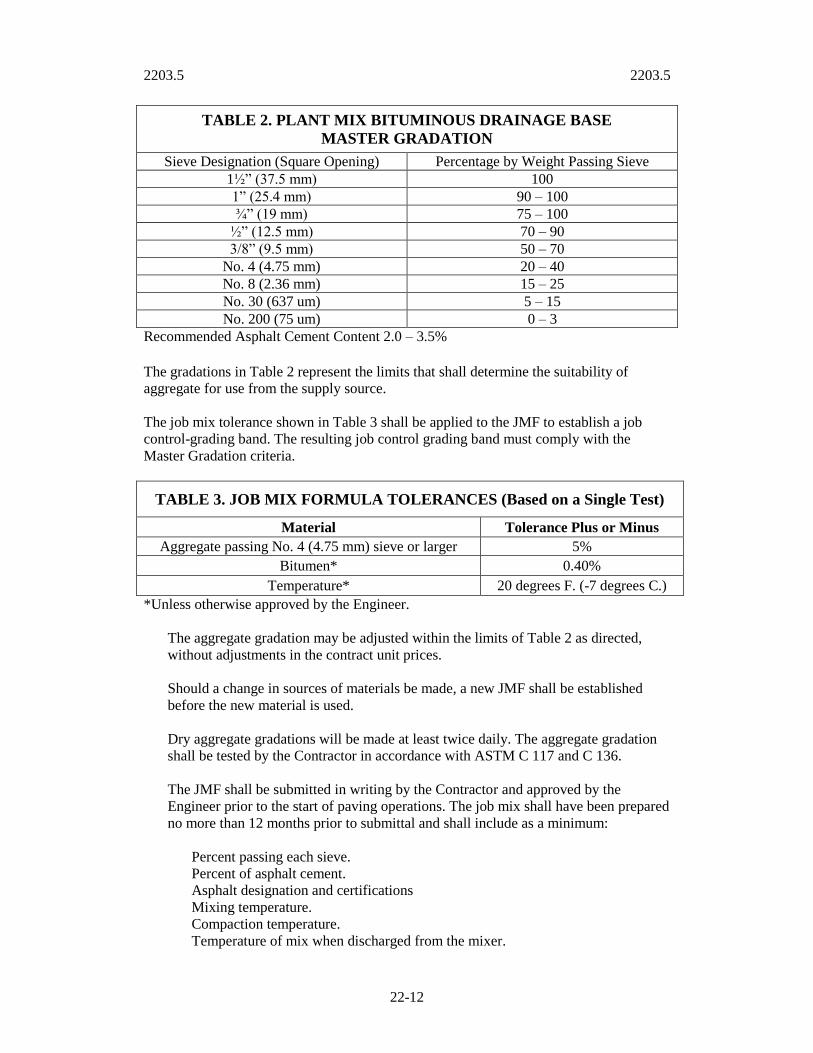
TABLE 2. PLANT MIX BITUMINOUS DRAINAGE BASE
MASTER GRADATION
Sieve Designation (Square Opening) Percentage by Weight Passing Sieve
1½” (37.5 mm) 100
1” (25.4 mm) 90 – 100
¾” (19 mm) 75 – 100
½” (12.5 mm) 70 – 90
3/8” (9.5 mm) 50 – 70
No. 4 (4.75 mm) 20 – 40
No. 8 (2.36 mm) 15 – 25
No. 30 (637 um) 5 – 15
No. 200 (75 um) 0 – 3
Recommended Asphalt Cement Content 2.0 – 3.5%
The gradations in Table 2 represent the limits that shall determine the suitability of
aggregate for use from the supply source.
The job mix tolerance shown in Table 3 shall be applied to the JMF to establish a job
control-grading band. The resulting job control grading band must comply with the
Master Gradation criteria.
TABLE 3. JOB MIX FORMULA TOLERANCES (Based on a Single Test)
Material Tolerance Plus or Minus
Aggregate passing No. 4 (4.75 mm) sieve or larger 5%
Bitumen* 0.40%
Temperature* 20 degrees F. (-7 degrees C.)
*Unless otherwise approved by the Engineer.
The aggregate gradation may be adjusted within the limits of Table 2 as directed,
without adjustments in the contract unit prices.
Should a change in sources of materials be made, a new JMF shall be established
before the new material is used.
Dry aggregate gradations will be made at least twice daily. The aggregate gradation
shall be tested by the Contractor in accordance with ASTM C 117 and C 136.
The JMF shall be submitted in writing by the Contractor and approved by the
Engineer prior to the start of paving operations. The job mix shall have been prepared
no more than 12 months prior to submittal and shall include as a minimum:
Percent passing each sieve.
Percent of asphalt cement.
Asphalt designation and certifications
Mixing temperature.
Compaction temperature.
Temperature of mix when discharged from the mixer.
2203.5 2203.5
22-13
Percent fractured faces.
Percent elongated particles.
The Contractor shall submit samples to the Engineer, upon request, for job mix
formula verification testing.
E. Test Section: Prior to full production, the Contractor shall prepare and place a
section of drainable base according to the JMF. The amount of mixture should be 80
tons (72.6 metric tons) and may be placed as part of the project. The underlying grade
or pavement structure upon which the test section is to be constructed shall be the
same as the remainder of the course represented by the test section. The equipment
used in construction of the test section shall be the same type and weight to be used
on the remainder of the course represented by the test section.
Two random samples of mixture may be taken at the plant and tested for aggregate
gradation and asphalt content. The test section shall be considered acceptable if the
gradation and asphalt content are within the limits specified in Tables 2 and 3.
If the initial test section should prove to be unsatisfactory to the Engineer, the
necessary adjustments to the JMF, plant operation, placing procedures, and/or rolling
procedures shall be made. A second test section shall then be placed. If the second
test section also does not meet specification requirements, both sections shall be
removed at the Contractor’s expense. Additional test sections, as required, shall be
constructed and evaluated for conformance to the specifications. Any additional
sections that do not conform to specification requirements shall be removed at the
Contractor’s expense. Full production shall not begin until a satisfactory section has
been constructed and accepted by the Engineer. The test sections that meet the
specification requirements shall be paid for in accordance with project quantities.
The Contractor shall perform Job mix control testing at the start of plant production
and in conjunction with the calibration of the plant for the JMF. It should be
recognized that the aggregates produced by the plant may not satisfy the gradation
requirements or produce a mix that exactly meets the JMF. In those instances, it will
be necessary to reevaluate and redesign the mix using plant-produced aggregates.
Specimens should be prepared and the optimum bitumen content determined in the
same manner as for the original design tests.
F. Testing Laboratory: The laboratory used to develop the JMF formula shall meet the
requirements of ASTM D 3666.
G. Construction Methods:
1. Weather Limitations: The bituminous mixture shall not be placed upon a wet
surface or when the surface temperature of the underlying course is less than 40
degrees F (4.4 degrees C) or the wind chill factor is less than 35 degrees F (1.7
degrees C). The temperature requirements may be waived by the Engineer;
however, all other requirements including compaction shall be met.
2. These materials will be placed, handled, hauled and accepted based on
requirements of Section 2205.

2203.5 2203.6
22-14
2203.6 Underdrains:
A. Summary: Underdrain construction shall consist of furnishing of all labor,
equipment and materials necessary for the complete installation of underdrains,
including pipe, geotextiles and granular filter material in accordance with these
specifications, standard drawings, the contract special provisions, and as shown on
the Plans or established by the Engineer.
B. Materials:
1. Aggregate: Blanket Underdrain Aggregate and Pipe Underdrain Aggregate shall
conform to requirements of Section 2203.3.a with the following gradations:
TABLE 2. BLANKET UNDERDRAIN AGGREGATE
Sieve Size Percent Passing by Weight
1½” (38.1 mm) 100
1” (25.4 mm) 90 – 100
¾” (19 mm) 60 – 90
3/8” (9.5 mm) -
No. 4 (4.75 mm) 0 – 20
No. 8 (2.4 mm) -
No. 16 (1.2 mm) 0 – 10
No.30 (0.6 mm) -
No. 50 (0.3 mm) 0 – 7
No. 100 (150 um) 0 – 2
TABLE 2. PIPE UNDERDRAIN AGGREGATE
Sieve Size Percent Passing by Weight
1½” (38.1 mm) -
1” (25.4 mm) -
¾” (19 mm) 100
3/8” (9.5 mm) 85 – 100
No. 4 (4.75 mm) -
No. 8 (2.4 mm) 40 – 60
No. 16 (1.2 mm) -
No.30 (0.6 mm) 5 - 30
No. 50 (0.3 mm) -
No. 100 (150 um) 0 – 2
2. Underdrain Pipe:
a. Polyvinyl chloride pipe shall meet the requirements of ASTM F758/D3034.
2203.6 2203.6
22-15
b. Corrugated Polyethylene Tubing. may be used only outside of traffic areas
and driving surfaces. The tubing shall be the heavy duty type and shall meet
the requirements of AASHTO M 252. In addition, the tubing shall have a
minimum pipe stiffness of 30 psi (210 kPa) at 10% deflection.
c. All underdrain pipes shall have a nominal minimum inside diameter of six
inches (150 mm) unless shown otherwise on the Plans.
d. Perforations shall be approximately circular and cleanly cut; shall have
nominal diameters not less than 3/16-inch (5 mm) nor more than 3/8-inch (10
mm); and shall be arranged in at least two rows parallel to the axis of the
pipe.
e. Fittings shall be of the same composition and have the same physical
properties as the pipe and shall not restrict flow.
3. Geocomposite Edge Drain:
a. Edge drain shall consist of a plastic core completely surrounded by
geotextile. The core shall provide a minimum of 10 percent open area to
facilitate water entry or cross flow and shall be composed of plastic which is
physically and chemically stable under a normal range of conditions.
b. The edge drain shall have nominal dimensions of 1 to 1-1/2 inches (25 to 40
mm) in thickness and 12 inches (305 mm) in height.
c. The edge drain shall have a minimum flow capacity of 15 gallons per minute
per foot of width (1.9 liters/cm) as determined by ASTM D4716 when tested
under a confining stress of 10 psi (70 kPa) or more at a gradient of 0.1 or
less.
d. The edge drain shall have a minimum compressive strength of either 7,000
psf (335 kPa) at a maximum deformation of 10 percent of the original
thickness when tested in accordance with ASTM D1621, or 8,000 psf (385
kPa) at a maximum deformation of 20 percent when tested in accordance
with ASTM D695.
e. Geotextile shall have an apparent opening size (AOS) corresponding to a
U.S. sieve number greater than 50 (0.3 mm) but not exceeding 100 (150 μm).
4. Geotextile: Geotextile for use with pipe and edge underdrains shall be a
nonwoven geotextile and shall meet the requirements of Section 2605.2.C.2.
C. Construction:
1. General: The exact location and layout of underdrains and/or edge drains as
shown on the Plans shall be subject to revision by the Engineer as determined
during construction.

2203.6 2203.6
22-16
2. Excavation:
a. Trenches for all lateral and longitudinal underdrains shall be excavated to the
dimensions, depths and elevations or as ordered by the Engineer. In case of a
conflict, where the actual elevation of the strata or stratum to be intercepted
is found to vary from Plan elevation, the stratigraphy shall govern in the
installation of underdrains.
b. Trench bottoms for perforated pipe underdrain and edge drain shall be in
firm material (no mucky or soupy condition existing) and constructed to
permit the placing of three inches (75 mm) of aggregate underneath the pipe.
If unstable material is encountered in the bottom of the trench, the trench
shall be over excavated to firm material.
c. Minimum width of trench shall be as shown on the Standard Plan.
3. Laying Pipe:
a. All underdrain pipe shall be laid carefully to line and grade.
b. All pipe shall be laid on a minimum grade of one percent unless otherwise
shown on the Plans.
c. All dead ends of pipe underdrains shall be completely closed with a cap of
the same material as the pipe.
d. All junctions and turns shall be made with wyes, tees, and bends as supplied
by the manufacturer of the pipe.
e. Perforations shall be laid down unless otherwise indicated on the Plans.
4. Installing Edge Drain:
a. Installation shall be in accordance with manufacturer’s instructions.
b. Each length of drain shall be joined to the adjacent length prior to
installation. Splices shall keep adjoining lengths in proper alignment, shall
not separate during installation, shall have the same or greater compressive
strength than the geocomposite drain, and shall be sealed against infiltration
of backfill material.
c. Drain shall be placed in the center of the trench and held in place with a
temporary support while blanket underdrain aggregate backfill is placed.
d. The placement of the edge drain and the first lift of backfill shall be
accomplished in a single continuous operation.
2203.6 2203.7
22-17
5. Backfilling:
a. Backfilling the trenches of lateral and longitudinal underdrains shall not be
started until approved by the Engineer.
b. The trenches shall be backfilled to the elevations shown on the Plans, in
accordance with the Standard Plan.
c. The backfill material shall be placed in such a manner as to prevent
formation of large cavities in the backfill and walls of the trench.
d. Overbreakage due to blasting of rock in trench excavation and widening due
to caving of trench walls or overbreakage at construction outcrops shall be
backfilled with aggregate.
2203.7 Permeability Test Procedure:
A. Summary: This test method is used to determine the permeability of unbound and
bound aggregate base material. Bound base material will use Portland Cement, Fly
Ash or Asphaltic Cement as a cementing agent.
B. Unbound Base and Base Bound with Fly Ash or Portland Cement:
1. Apparatus:
a. Mold: A cylindrical metal mold with an approximate inside diameter of 152
mm (6") and a minimum height of 152 mm (6"). The mold shall be equipped
with a removable collar at least 51 mm (2") in height and a removable base
plate. The base plate may be used as part of the permeability test equipment.
If so, the base plate must exceed the permeability of the material being
tested. A #40 screen shall be placed on top of the base plate to prevent test
material from being lost through the base plate during compaction and
permeability testing.
b. Standpipe: A standpipe with the same diameter as the removable collar for
the mold with a minimum height of 216 mm (8.5"). The standpipe shall be
equipped with an overflow outlet.
c. Rammer: A mechanically operated metal rammer equipped to control the
height of drop to 305 mm (12") plus or minus 2 mm (1/16") above the
elevation of the sample. The rammer shall be equipped to distribute the blow
uniformly over the sample surface. The rammer shall have a rigid flat faced
"pie shaped" foot and a nominal weight of 25 kg (5.50 lbs.). The "pie
shaped" foot shall be a sector of 152 mm (6") diameter circle and shall have
an area equal to that of 51 mm (2") circular foot.
d. Straight edge: A rigid steel straight edge with one edge beveled, at least 203
mm (8") in length.

2203.7 2203.7
22-18
2. Sample preparation:
a. Obtain a 22.7 kg (50 lb.) to 27.2 kg (60 lb.) sample, dry if necessary.
b. Mix a sufficient amount of aggregate and cementing agent, if required, to fill
the mold 1 and 1/2 times.
c. Add the appropriate amount of water and thoroughly mix.
d. Place the assembled mold on the rigid base and fill approximately ½ full of
the loose moist material. Compact the layer with 25 blows of the rammer
with the blows being distributed uniformly over the surface of the layer.
Place three additional approximately equal layers of material in the mold and
compact each layer in a similar manner (four layers total).
e. After the fourth layer has been compacted, remove the collar and trim excess
material level with top of the mold.
f. Cure Portland Cement and Fly Ash treated specimens by covering with
plastic, to prevent drying for 3 days at room temperature.
g. Unbound specimens do not need to be cured before testing.
C. Asphalt Bound Aggregates:
1. Apparatus:
a. Mold: A cylindrical mold with an inside diameter of approximately 152 mm
(6") and a minimum length of 114 mm (4.5"). The mold is open at each end
and is equipped with a removable collar and a base plate about 13 mm (0.5")
thick.
b. Specimen Mold Holder: The specimen mold holder has a semi circular base
and a flanged top to hold the specimen mold in place during the compaction
process. Any equivalent hold down device that performs the same function is
satisfactory.
c. Compaction Hammer: The compaction hammer consists of a hammer
having a flat circular tamping face 149 mm (5.88") in diameter and
appropriate extension rod with handle which acts as guide for a free falling
weight. The weight shall weigh 10 kg (22.5 lbs.) and have a free fall of 547
mm (18") plus or minus 2 mm (0.1"). The hammer may be operated
manually or be driven with a motor.
d. Compaction Pedestal: The compaction pedestal is a wood block
approximately 305 mm x 305 mm x 457 mm (12" x 12" x 18"). A 305 mm x
305 mm x 25 mm (12" x 12" x 1") steel plate is securely fastened to the top
of the block. The pedestal is set on and securely fastened to a solid concrete
slab with the vertical axis plumb and the top level.

2203.7 2203.7
22-19
e. Heating Equipment: Ovens or hot plates for heating aggregates, bituminous
material, specimen molds, compaction hammers and other associated items
required for mixing and molding. It is recommended that, when possible all
heating units be thermostatically controlled to maintain the required
temperature within ± 2.8°C (5°F). Suitable shields, thick steel plates or pans
of sand shall be used on the surfaces of hot plates to minimize locally
overheating.
f. Mixing Apparatus: Mechanical mixing is recommended. Any type of
mechanical mixer may be used provided it will produce a well coated,
homogeneous mixture of the required amount in the allowable time and
further that the mixing paddle or whip does not fracture or pulverize
aggregate fractions during the mixing process. The bowl employed with the
mixer shall be such a nature that essentially all of the batch can be removed.
More than one mixing bowl is recommended unless the mixer is equipped
with a heating jacket to keep the bowl heated during the mixing process.
2. Determination of Mixing and Compacting Temperature:
a. The temperature to which the asphalt cement must be heated to produce a
viscosity of 85 ± 10 SFS shall be the mixing temperature.
b. The temperature to which the asphalt cement must be heated to produce a
viscosity of 130 ± 15 SFS shall be the compacting temperature.
3. Sample Preparation for Laboratory Prepared Mix:
a. Combine the dry individual aggregates to produce desired combined aggregate
with a batch weight of approximately 4050 grams (8.9 lbs.). This should be
sufficient to produce a compacted specimen 95 ± 3 mm (3.75 ± 0.125 inches)
thick. Adjust the weight of the batch as needed to produce a compacted specimen
of 95 ± 3 mm (3.75 ± 0.125 inches) thick.
b. Prepare a minimum of two aggregate and asphalt specimens. The first specimen
shall be mixed and thrown away. This sample is to "butter" the mixing bowl and
paddle and thus reduce material loss when mixing the test specimen.
c. Heat the aggregate and asphalt within the limits of mixing temperature
determined in paragraph 2203.7 C2a. Charge the mixing bowl with the heated
aggregate and form a crater in the top. Add the required amount asphalt and mix
the aggregate and asphalt until coated at least 2 minutes. Care should be taken to
keep all of the sample in the mixing bowl during this process.
4. Compaction of Specimen:
a. Prior to the addition of the asphalt to the batches, thoroughly clean the specimen
mold assembly and the face of the compaction hammer and heat the mold
assembly and hammer to a temperature between 93.3°C (200°F) and 176.7°C
(350°F). Assemble the mold, base plate and collar and place a paper disc cut to
size in the bottom of the mold.

2203.7 2203.7
22-20
b. Place the hot batch of aggregate-asphalt mixture in the mold, spade vigorously
with a heated spatula or trowel 15 times around the perimeter and 10 times over
the interior of the mold. Smooth the surface of the mix to a slightly rounded
shape. The temperature of the mix prior to compaction shall be within the limits
in 2203.7 C2b. Place a paper disc on top of the mix.
c. Place the mold assembly, including the collar, on the pedestal, fasten securely
with the mold holder and apply 20 blows with the compactionhammer. Each low
must have the prescribed free fall of 457 mm (18") with the axis of the
compaction hammer held perpendicular to the base of the mold assembly during
the compaction process. Remove the base plate and collar, and reverse and
reassemble the mold. Apply the specified number of blows to the reversed
specimen. After compaction remove the mold assembly from the pedestal,
remove the collar and base plate and cool the specimen in the mold until the
mold can be handled comfortable with bare hands. Asphalt treated samples do
not need to be cured before testing, only cool to the touch.
D. Test Procedure:
1. Assemble test equipment, base plate, mold with specimen, and standpipe.
2. Prior to conducting the test, allow a sufficient amount of water to pass through
the specimen to cause all air to be expelled from the specimen. (Establish
reservoir around the base with water open to atmospheric pressure.)
3. Conduct Constant-Head Permeability test and report coefficient of permeability
"k" in meters (feet) per day. Repeat a minimum of two additional times until two
runs agree reasonably well.
4. Constant-Head Permeability:
QL
K = ----------
Aht
Q = quantity of water discharged (volume)
L = length of specimen
A = cross-sectional area of specimen
h = hydraulic head (height column of water above discharge)
t = elapsed time of test
K= coefficient of permeability (length/time)
Note: For very permeable material, maintain elevation of water above the sample
for 3 minutes then measure Q (flow).

2203.7 2203.9
22-21
2203.8 Methods of Measurement:
A. Crushed Aggregate Drainable Base will be measured by one of the following:
1. Per square yard (square meter) or tenth part thereof for the specified depth.
2. Per ton (metric ton) or tenth part thereof.
B. Portland Cement Concrete Drainable Base may be included in the Proposal as a
single item or as separate items (Portland Cement and Base Aggregate) and measured
by one of the following:
1. Per square yard (square meter) or tenth part thereof for the specified depth.
2. Per ton (metric ton) or tenth part thereof.
C. Plant Mix Bituminous Drainable Base may be included in the Proposal as a single
item or as separate items (Asphaltic Cement and Base Aggregate) and measured by
one of the following:
1. Per square yard (square meter) or tenth part thereof for the specified depth.
2. Per ton (metric ton) or tenth part thereof.
D. Pipe Underdrains will be measured per lineal foot (meter) or tenth part thereof.
Drainable Base Aggregate shall be subsidiary to the Pipe Underdrain.
E. Blanket Underdrains will be measured by the actual quantities used as follows:
1. Pipe Underdrain will be measured per lineal foot (meter) or tenth part thereof.
2. Drainable Base Aggregate will be measured by one of the following:
a. Per square yard (square meter) or tenth part thereof for the specified depth.
b. Per ton (metric ton) or tenth part thereof.
2203.9 Basis of Payment:
A. Crushed Aggregate Drainable Base will be paid for by one of the following:
1. Contract unit bid price.
2. Contract lump sum bid price.
B. Portland Cement Concrete Drainable Base will be paid for by one of the following:
1. Contract unit bid price.
2. Contract lump sum bid price.

2203.9 2203.9
22-22
C. Plant Mix Bituminous Drainable Base will be paid for by one of the following:
1. Contract unit bid price.
2. Contract lump sum bid price.
D. Pipe Underdrains will be paid for by one of the following:
1. Contract unit bid price.
2. Contract lump sum bid price.
E. Blanket Underdrains will be paid for by one of the following:
1. Contract unit bid price.
2. Contract lump sum bid price.

2204 2204.2
22-23
SECTION 2204 PRIME AND TACK COAT
Referenced Standards: The following standards are referenced directly in this section.
The latest version of these standards shall be used.
ASTM
D 140 - Practice for Sampling Bituminous Materials
2204.1 Summary: This section includes the application of liquid asphalt to a prepared
pavement (concrete, asphaltic concrete), or granular base. The type and grade of asphalt
material to be used as prime or tack coat, is as specified in the Special Provisions or as
indicated by the plans.
2204.2 Liquid Asphalt Material: The liquid asphalt material to be used for surface
preparation shall be as listed in the following table:
Material
to be used
Application
Usage
Type of
Emulsion
or Grade
of
Cutback
Application
Rate
Gal/SY (L/SM)
Application
Temperature
*F (*C)
Cure Time
at
70ºF
(21ºC)
Existing Asphalt
or Concrete
Surface
Tack RC-70 0.05-0.10 Gal/SY
(0.23-0.46 L/SM)
150-225
(65-107) 1-6 hrs
Tack
SS-1
SS-1h
CSS-1
CSS-1h
0.05-0.10 Gal/SY
(0.23-0.69 L/SM)
70-160
(22.5-42) 1-3 hrs
Treated Base; i.e., lime, fly/ash,
cement
Prime MC-30
MC-70 0.1-0.3 Gal/SY
(0.46-1.38 L/SM) 85-120
(29-49) 12-24 hrs
Prime
SS-1 SS-1h
CSS-1
CSS-1h
0.1-0.3 Gal/SY/in
(0.46-1.38 L/SM/mm)
70-160
(20-70) 24-48 hrs
Untreated
Aggregate Base
w/Fines
Prime MC-30,
MC-70 0.1-0.3 Gal/SY
(0.46-1.38 L/SM) 85-120
(29-49) 12-24 hrs
W/O Fines Prime MC-250 0.2-0.5 Gal/SY
(0.92-2.30 L/SM) 85-120
(29-49) 12-24 hrs
Untreated
Aggregate Base
Prime
SS-1
SS-1h
CSS-1 CSS-1h
0.1-0.3 Gal/SY/in (0.46-1.38
L/SM/mm)
70-160
(20-70) 24-48 hrs
Prime EAP
PAE, or
PEP
0.1-0.3 Gal/SY
(0.46-1.38 L/SM) 70-160
(20-70) 24-48 hrs
The asphalt material shall conform to the latest ASTM specifications for "Asphalt
Cements and Liquid Asphalts." Sampling shall be in accordance with ASTM D 140.

2204.2 2204.7
22-24
2204.3 Sand Cover: Sand Cover, if used, shall be any clean granular mineral meeting the
following grading requirements. When tested with laboratory sieves 100% shall pass the
No. 4 (4.75 mm) sieve and not more than 2% shall pass the No. 200 (75 um) sieve. The
moisture content of the sand shall not exceed 3% by weight.
2204.4 Approval of Materials: Asphalt materials shall be approved by the Engineer
prior to use in the work. The Engineer may accept a certified analysis by the material
supplier laboratory when a copy of the certified analysis accompanies each shipment of
asphalt to the project. The Engineer reserves the right to perform tests of the asphalt
received on the job.
2204.5 Pressure Distributor: The distributor shall be so designed, equipped, maintained
and operated that liquid asphalt at even heat may be applied uniformly on variable widths
of surface up to 15 feet (4.5 m) at readily determined and controlled rates from 0.02 to
1.00 gallon per square yard (100 to 5000 milliliters per square meter), with uniform
pressure, and with an allowable variation from any specified rate not to exceed 0.02
gallons per square yard (100 milliliters per square meter). Distributor equipment shall
include a tachometer, pressure gauges, a calibrated tank and a thermometer for measuring
temperatures of tank contents. Distributors shall be equipped with a power unit for the
pump, and full circulation spray bars adjustable laterally and vertically. The calibration of
all distributors must be approved by the engineer, and the contractor shall furnish all
equipment, material and assistance necessary if calibration is required.
2204.6 Preparation of Existing Surface:
A. For tack coats: The existing surface shall be free of all dust, loose material, grease
or other foreign material at the time the tack is applied. Any excess surface oil on the
roadway or bituminous joint material will be removed by others without cost to the
contractor before the tack is applied.
B. For prime coats: the surface to be primed shall be shaped to the required grade and
cross section, shall be free from all ruts, corrugations, segregated material or other
irregularities, and shall be uniformly compacted by rolling. The surface shall be firm
and slightly damp when primer is applied. Delays in priming may necessitate
reprocessing or reshaping to provide a smooth compacted surface.
2204.7 Application of Asphalt Material:
A. For Tack Coats: Asphalt emulsion shall be applied uniformly with a pressure
distributor at the rate specified in the contract, or as revised by the engineer to be
within a minimum of 0.05 and a maximum of 0.15 gallons per square yard (minimum
of 230 and a maximum of 690 milliliters per square meter). Water may be added to
the asphalt emulsion and mixed therewith in such proportion that the resulting
mixture will contain not more than 50% of added water, the quantity of added water
to be approved by the engineer. The application of the resulting mixture shall be such
that the original emulsion will be spread at the specified rate. The asphalt emulsion
shall be heated at the time of application to a temperature in accordance with the
limits provided in Sec 2204.2, or as specified in the contract. The tack shall be
properly cured and the tacked surface shall be cleaned of all dirt and surplus sand
before the next course is placed.

2204.7 2204.10
22-25
The tack coat shall be applied in such manner as to cause the least inconvenience to
traffic and to permit one-way traffic without pickup or tracking of the asphalt
emulsion.
B. For Prime Coats: Bituminous material shall be applied to the width of the section to
be primed by means of a pressure distributor in a uniform, continuous spread. The
subgrade shall be moistened before the prime is applied. The application rate shall be
as specified in the contract or as approved by the engineer between 0.1 and 0.5
gallons per square yard (0.46 and 2.30 liters per square meter). The primer shall be
heated at the time of application to a temperature in accordance with the limits
provided in Sec 2204.2, or as specified in the contract.
Care shall be taken that the application of bituminous material at the junctions of
spreads is not in excess of the specified quantity. Building paper shall be placed over
the end of the previous applications and the joining application shall start on the
building paper. Building paper used shall be removed and satisfactorily disposed of.
Pools of primer material remaining on the surface after the application shall be
removed.
When traffic is maintained, not more than one half of the width of the section shall be
treated in one application and one-way traffic will be permitted on the untreated
portion of the roadbed. As soon as the bituminous material has been absorbed by the
surface and will not pick up, traffic shall be routed to the treated portion and the
remaining width of the section will be primed. The primer shall be properly cured,
and the primed surface shall be cleaned of all dirt and surplus sand before the next
course is placed.
2204.8 Application of Sand Cover: If the asphalt material is not completely cured
within the maximum specified curing time, sufficient sand shall be spread over the
surface with a mechanical spreader to blot up the excess asphalt. The rate of application
shall be specified or approved by the Engineer. Prior to placing an asphalt paving course,
all loose sand shall be swept from the primed or tacked surface.
2204.9 Methods of Measurement: Asphalt Prime and Tack Coat will be measured per
gallon (liter).
2204.10 Basis of Payment: Asphalt Prime and Tack Coat will be paid for at the contract
unit bid price.
2205 2205
22-26
SECTION 2205 ASPHALTIC CONCRETE SURFACE AND BASE
Referenced Standards: The following standards are referenced directly in this section.
The latest version of these standards shall be used.
ASTM
C 88 - Test Method for Soundness of Aggregates by Use of Sodium Sulfate or
Magnesium Sulfate
C 117 - Test Method for Materials Finer than 75- um (No. 200) Sieve in Mineral
Aggregates by Washing
C 127 - Test Method for Specific Gravity and Absorption of Coarse Aggregate
C 128 - Test Method for Specific Gravity and Absorption of Fine Aggregate
C 131 - Test Method for Resistance to Degradation of Small-Size Coarse Aggregate by
Abrasion and Impact in the Los Angeles Machine
C 136 - Test Method for Sieve Analysis of Fine and Coarse Aggregates
C 142 - Test Method for Clay Lumps and Friable Particles in Aggregates
D 75 - Practice for Sampling Aggregates
D 140 - Practice for Sampling Bituminous Materials
D 290 - Practice for Bituminous Mixing Plant Inspection
D 979 - Practice for Sampling Bituminous Paving Mixtures
D 1188 - Test Method for Bulk Specific Gravity and Density of Compacted Bituminous
Mixtures Using Paraffin-Coated Specimens
D 2041 - Test Method for Theoretical Maximum Specific Gravity and Density of
Bituminous Paving Mixtures
D 2172 - Test Methods for Quantitative Extraction of Bitumen from Bituminous Paving
Mixtures
D 2726 - Test Method for Bulk Specific Gravity and Density of Non-Absorptive
Compacted Bituminous Mixtures
D 2950 - Test Method for Density of Bituminous Concrete in Place by Nuclear Methods
D 3666 - Specification for Minimum Requirements for Agencies Testing and Inspecting
Bituminous Paving Materials
D 4552 - Practice for Classifying Hot-Mix Recycling Agents
D 5444 - Test Method for Mechanical Size Analysis of Extracted Aggregate
D 6307 - Test Method for Asphalt Content of Hot-Mix Asphalt by Ignition Method
D 6373 - Specification for Performance Graded Asphalt Binder
AASHTO
PP 26 Practice for Certifying Suppliers of Performance Graded Asphalt Binders
T 245 Resistance to Plastic Flow of Bituminous Mixtures Using Marshall Apparatus
T 283 Resistance of Compacted Bituminous Mixture to Moisture Induced Damage
Asphalt Institute
“Mix Design Methods for Asphalt Concrete and Other Hot-Mix Types”, MS-2, Sixth
Edition
“Superpave Performance Graded Asphalt Binder Specification and Testing”, SP-1
“Superpave Mix Design”, SP-2
National Bureau of Standards
Handbook #44, “Specifications, Tolerance and other Technical Requirements for
Commercial Weighing and Measuring Devices”

2205.3 2205.3
22-27
2205.1 Summary: This section includes the construction of asphalt concrete base and/or
asphalt concrete surface. All materials and placement shall be tested as outlined in the
“Public Works Department Materials Testing Requirements”.
2205.2 Materials: No material shall be used until approved by the engineer. All
costs associated with material testing, certification and the preparation of trial
mixes to determine the job mix formula shall be the responsibility of the
contractor. Representative KCMO (Feb 15, 2002) 2 samples of all materials
proposed for use under these specifications shall be submitted to a City approved
private testing laboratory by the contractor, at the contractor’s expense, for testing
and the preparation of trial mixes to determine the job-mix formula. Additional
tests necessary for determining conformance with the requirements specified
herein will be performed under the supervision of the engineer without cost to the
contractor, unless testing is the responsibility of the contractor.
A. Asphalt: Asphalt cement used in the manufacture of asphalt paving mixtures shall
conform to the Performance Graded system. The PG graded material used shall
conform to the provincial grade used by the local DOT or as designated by the
Engineer. In the Kansas City Metropolitan area, the provincial grade is a PG64-22.
These general usage guidelines may not address all project conditions. APWA
strongly recommends that the engineer apply sound pavement design principles when
designating mix type and selecting asphalt cement grade based upon individual
project conditions. The Federal Highway Administration makes available
LTPPBIND software that will assist with asphalt grade selection for specific projects.
The asphalt cement shall conform to ASTM D 6373. Sampling shall be in accordance
with ASTM D 140.
The contractor or asphalt supplier shall submit a quality assurance plan for the
asphaltic cement to the engineer that conforms to AASHTO PP 26. He shall also
submit a temperature-viscosity chart showing the recommended mix and compaction
temperatures for non-modified asphalts, and shall provide the specific gravity of the
asphalt.
B. Aggregate: The quality of aggregates used in Asphaltic Concrete shall conform to
the following:
Coarse Aggregate (Retained on the No. 4 Sieve)
LA Abrasion (ASTM C 131) 35% loss (maximum)
Soundness using Mag. Sulfate (ASTM C 88 5 cycles) 15% loss (maximum)
Total shale, clay, coal and lignite content ASTM C 142 1.0% by weight (max)
Fine Aggregate (Passing the No. 4 Sieve)
Organic content 1% maximum 1.0 maximum
The parent material of manufactured sand must also meet the requirements for
coarse aggregate shown above.
Sampling shall be in accordance with ASTM D 75. Gradation analysis shall be in
accordance with Standard Method of Test for Material Finer than No. 200 (75 um) Sieve
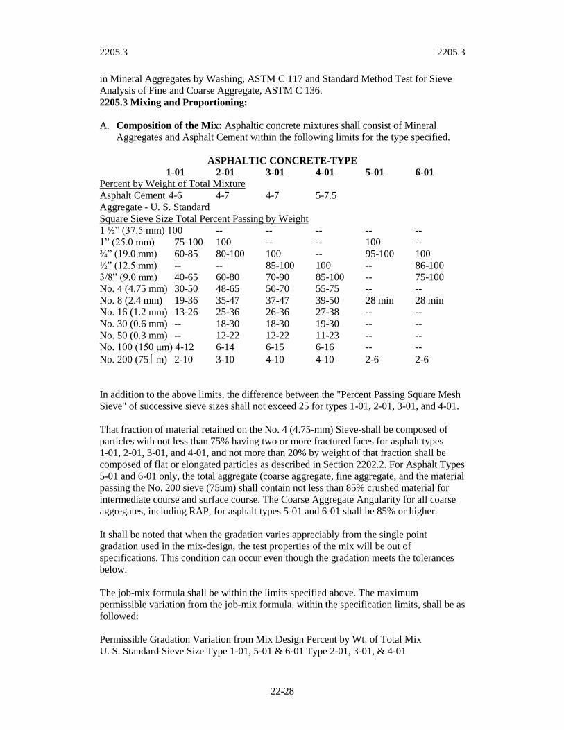
2205.3 2205.3
22-28
in Mineral Aggregates by Washing, ASTM C 117 and Standard Method Test for Sieve
Analysis of Fine and Coarse Aggregate, ASTM C 136.
2205.3 Mixing and Proportioning:
A. Composition of the Mix: Asphaltic concrete mixtures shall consist of Mineral
Aggregates and Asphalt Cement within the following limits for the type specified.
ASPHALTIC CONCRETE-TYPE
1-01 2-01 3-01 4-01 5-01 6-01
Percent by Weight of Total Mixture
Asphalt Cement 4-6 4-7 4-7 5-7.5
Aggregate - U. S. Standard
Square Sieve Size Total Percent Passing by Weight
1 ½” (37.5 mm) 100 -- -- -- -- --
1” (25.0 mm) 75-100 100 -- -- 100 --
¾” (19.0 mm) 60-85 80-100 100 -- 95-100 100
½” (12.5 mm) -- -- 85-100 100 -- 86-100
3/8” (9.0 mm) 40-65 60-80 70-90 85-100 -- 75-100
No. 4 (4.75 mm) 30-50 48-65 50-70 55-75 -- --
No. 8 (2.4 mm) 19-36 35-47 37-47 39-50 28 min 28 min
No. 16 (1.2 mm) 13-26 25-36 26-36 27-38 -- --
No. 30 (0.6 mm) -- 18-30 18-30 19-30 -- --
No. 50 (0.3 mm) -- 12-22 12-22 11-23 -- --
No. 100 (150 μm) 4-12 6-14 6-15 6-16 -- --
No. 200 (75 m) 2-10 3-10 4-10 4-10 2-6 2-6
In addition to the above limits, the difference between the "Percent Passing Square Mesh
Sieve" of successive sieve sizes shall not exceed 25 for types 1-01, 2-01, 3-01, and 4-01.
That fraction of material retained on the No. 4 (4.75-mm) Sieve-shall be composed of
particles with not less than 75% having two or more fractured faces for asphalt types
1-01, 2-01, 3-01, and 4-01, and not more than 20% by weight of that fraction shall be
composed of flat or elongated particles as described in Section 2202.2. For Asphalt Types
5-01 and 6-01 only, the total aggregate (coarse aggregate, fine aggregate, and the material
passing the No. 200 sieve (75um) shall contain not less than 85% crushed material for
intermediate course and surface course. The Coarse Aggregate Angularity for all coarse
aggregates, including RAP, for asphalt types 5-01 and 6-01 shall be 85% or higher.
It shall be noted that when the gradation varies appreciably from the single point
gradation used in the mix-design, the test properties of the mix will be out of
specifications. This condition can occur even though the gradation meets the tolerances
below.
The job-mix formula shall be within the limits specified above. The maximum
permissible variation from the job-mix formula, within the specification limits, shall be as
followed:
Permissible Gradation Variation from Mix Design Percent by Wt. of Total Mix
U. S. Standard Sieve Size Type 1-01, 5-01 & 6-01 Type 2-01, 3-01, & 4-01

2205.3 2205.3
22-29
No. 4 (4.75 mm) and larger 5.0 4.0
No. 8, 16, 30 and 50 4.0 3.0 (2.4, 1.2, 0.6, 0.3 mm)
No. 200 (75 um) 2.0 1.0
Asphalt Cement 0.5 (1-01 only) 0.3
B. Asphalt Mix General Usage
Surface Base
Arterial 5-01, 6-01 1-01, 5-01
Collector , 5-01, 6-01 1-01, , 5-01
Local/Access , 3-01, 5-01 1-01, 2-01 , 5-01
Paved Trail 2-01, 3-01, 4-01, 5-01 1-01. 2-01, 5-01
Recreational Surface 4-01 1-01, 2-01, 5-01
Parking Lot 2-01, 3-01, 5-01 1-01. 2-01. 5-01
C. Asphalt Hot-Mix Recycling:
1. General: Except as modified herein, Recycled Asphaltic Concrete (RAC) shall
be equal to that produced as new material. Reclaimed Asphalt Pavement (RAP)
and/or Reclaimed Aggregate Materials (RAM) shall represent no more than 30%
of the composition for all surface mixtures and no more than 50% of the
composition for all base mixtures except type 5-01 and 6-01 (no more than 30%).
Only virgin materials shall be used in the surface course for new construction
projects. Recycled or virgin materials may be used on restoration projects.
Recycled Asphaltic Concrete may contain combinations of RAP, RAM, coarse
aggregate, fine aggregate, mineral filler, asphalt cement, recycling agent, anti-
stripping agent and approved additives to produce an acceptable mixture.
Recycled Asphaltic Concretes shall be designated by prefacing the type with
“RC,” such as “RC Type 1-01”. Fractionated RAP (FRAP) shall be recognized as
fine aggregate that passes the ¼ inch screen, and coarse aggregate as that
material retained on the ¼ inch screen and passing the ¾ inch screen.
2. Materials Evaluation: All recycled materials shall have the following
tests performed in addition to those required in 2205.3.D.:
a. A sieve analysis shall be performed on RAP and/or RAM in accordance with
ASTM C 117, "Standard Test Method for Material Finer than No. 200 Sieve
(75 um) in Mineral Aggregates by Washing" and ASTM C 136, "Standard
Method for Sieve Analysis of Fine and Coarse Aggregates" after extraction
of asphalt.
b. Asphalt content analysis shall be performed for RAP in accordance with
Method "A" of ASTM D 2172 , "Standard Test Methods for Quantitative
Extraction of Bitumen from Bituminous Paving Mixtures" where the RAP
content exceeds 30%. For mixtures with RAP contents less than 30%, asphalt
content may be determined using ASTM D6307.
c. The asphalt cement used shall be determined as follows:

2205.3 2205.3
22-30
For all hot mix asphalt containing RAC, the asphalt grade of the post
production mix shall be tested in accordance with procedures outlined in the
Apshalt Institute SP-1 to ensure that the asphalt grade meets or exceeds
PG64-22.
d. All sources of material for use in RAC must be approved by the Engineer
prior to use.
3. Material Requirements:
a. New asphalt cements added to the aged asphalt shall meet the requirements
of Section 2205.2A
b. Recycling Agents, if used, shall meet the requirements of ASTM D 4552,
"Standard Practice for Classifying HOT MIX Recycling Agents."
c. The RAP and/or RAM stockpiled at the plant site shall be maintained in
stockpiles separated into surface and base. The RAP and/or RAM shall be
processed such that 100% will pass the 1-1/2 inch (38 mm) sieve and 90%
will pass the 1-inch (25.4 mm) sieve.
d. The final product shall be free of foreign matter (e.g., old planer teeth, ice,
wood, soil, broken sewer castings, loop detector wire, protective membranes,
rubberized joint filler materials and foil turn lane markers, trash, debris, etc.)
4. Mix Design Requirements: The necessary steps for a final mix design for
recycled mixtures, shall be done in accordance with the Asphalt Institute's
Manual MS-2 Sixth Edition in the appendix entitled "Mix Design Using RAP
When a change in the RAP and/or RAM percentage exceeds 15% of the
original amount of RAP and/or RAM in the mix design, a new mix design
must be submitted.
5. Asphalt Plant Requirements: All delivery tickets shall designate the type of
recycled mix, (RC-Type 1-01, RC-Type 2-01, RC-Type 3-01, or RC-Type
4-01).
D. Mix Design Criteria: Laboratory Test Specimen(s) of the Paving Mix, combined in
proportions of the job-mix formula, shall be prepared and tested in accordance with
AASHTO T 245 and the volumetric properties of the compacted paving mixtures as
calculated by ASTM procedures using Chapter 4 of the Mix Design Methods for
Asphalt Concrete and other Hot-Mix types (MS-2), Sixth Edition, Asphalt Institute
referred hereafter as “MS-2”. The Marshall procedure and the Voids in the Mineral
Aggregate (VMA) shall be as specified in Chapter 5 of the MS-2. The automatic
Marshall Hammer may be used when it has been calibrated with a manual hammer.
For mix type 5-01 and/or 6-01 the procedures outlined in Asphalt Institutes SP-2
must be used to prepare the asphalt samples for design and quality control testing.
The gyratory values for the Super Gyratory Compactor (SGC) to be used for this
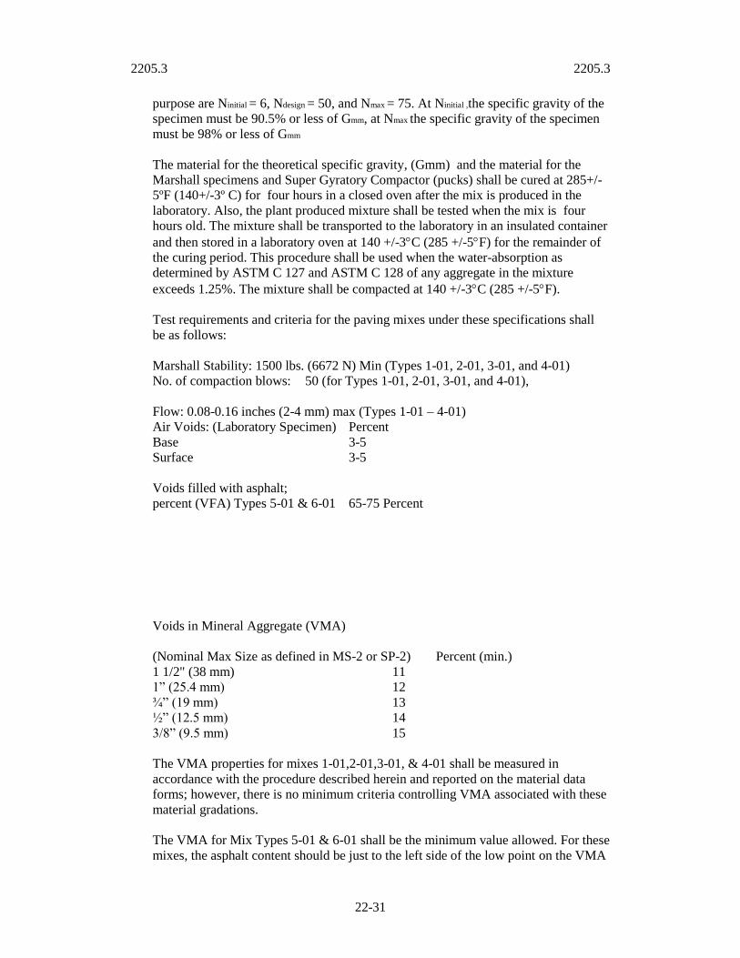
2205.3 2205.3
22-31
purpose are Ninitial = 6, Ndesign = 50, and Nmax = 75. At Ninitial ,the specific gravity of the
specimen must be 90.5% or less of Gmm, at Nmax the specific gravity of the specimen
must be 98% or less of Gmm
The material for the theoretical specific gravity, (Gmm) and the material for the
Marshall specimens and Super Gyratory Compactor (pucks) shall be cured at 285+/-
5ºF (140+/-3º C) for four hours in a closed oven after the mix is produced in the
laboratory. Also, the plant produced mixture shall be tested when the mix is four
hours old. The mixture shall be transported to the laboratory in an insulated container
and then stored in a laboratory oven at 140 +/-3C (285 +/-5F) for the remainder of
the curing period. This procedure shall be used when the water-absorption as
determined by ASTM C 127 and ASTM C 128 of any aggregate in the mixture
exceeds 1.25%. The mixture shall be compacted at 140 +/-3C (285 +/-5F).
Test requirements and criteria for the paving mixes under these specifications shall
be as follows:
Marshall Stability: 1500 lbs. (6672 N) Min (Types 1-01, 2-01, 3-01, and 4-01)
No. of compaction blows: 50 (for Types 1-01, 2-01, 3-01, and 4-01),
Flow: 0.08-0.16 inches (2-4 mm) max (Types 1-01 – 4-01)
Air Voids: (Laboratory Specimen) Percent
Base 3-5
Surface 3-5
Voids filled with asphalt;
percent (VFA) Types 5-01 & 6-01 65-75 Percent
Voids in Mineral Aggregate (VMA)
(Nominal Max Size as defined in MS-2 or SP-2) Percent (min.)
1 1/2" (38 mm) 11
1” (25.4 mm) 12
¾” (19 mm) 13
½” (12.5 mm) 14
3/8” (9.5 mm) 15
The VMA properties for mixes 1-01,2-01,3-01, & 4-01 shall be measured in
accordance with the procedure described herein and reported on the material data
forms; however, there is no minimum criteria controlling VMA associated with these
material gradations.
The VMA for Mix Types 5-01 & 6-01 shall be the minimum value allowed. For these
mixes, the asphalt content should be just to the left side of the low point on the VMA

2205.3 2205.3
22-32
vs. Asphalt Percent curve, not to the “wet” or right (increasing) side of the curve. The
VMA requirements shown represent values that may be higher than those obtained in
the KC Metropolitan area using locally available materials. VMA values shown are
for 4% air voids and should be used for the design of conventional roadway
pavements. During production, the voids can be expected to vary plus or minus 1%
of this design value of 4%. For mix types 1-01, 2-01, 3-01, and 4-01, 3% air voids
may be used for design. and production may be allowed to vary plus or minus 1% of
the design value.
The ratio of minus 200 (75 um) material to % Effective asphalt cement (Peff) based on
the weight of the aggregate shall be between 0.6-1.2 for Types 5-01 and 6-01.
The blend of RAP and/or RAM and virgin aggregates or non recycled asphalts shall
be checked for resistance to stripping using AASHTO T 283 to determine if an
antistripping agent is needed for the same asphalt chosen for the project. The index of
retained strength shall exceed 80% for Types 1-01 – 4-01, and 80% for types 5-01
and 6-01.
E. Sampling and Testing of the Mixture: Mixes shall be sampled in accordance with
ASTM D 979 and tested in accordance with AASHTO T 245. The mixtures will be
tested for binder content in accordance with ASTM D 2172 or D 6307. The recovered
aggregate will be sieved in accordance with ASTM D 5444.
F. Mixture Temperature Requirements: The temperature of the completed mix at the
plant and at the paver shall be set by the Contractor who shall consider hauling and
placing conditions, asphalt specifications as set forth in section 2205.2, and weather
limitations set forth in section 2205.8 (B). The temperature of Types 5-01 and 6-01
shall not exceed 315F (157C) at the point of discharge from the asphalt plant
when using PG 64-22 asphaltic oil.
When the mix is produced in a batch-type plant, the aggregate shall be weighed
accurately in the designated proportions to provide the specified batch weight. The
temperature of the aggregate at the time of introduction into the mixer shall be
determined by the contractor, with a tolerance of + or - 25º F (16º C). In no case,
however, shall the temperature of the mixture exceed the maximum temperature
recommended by the manufacturer or supplier of the asphaltic cement (generally
350º F (177º C).
G. Control of Mixing Time: The contractor shall control mixing time to produce
asphaltic concrete that is uniformly and thoroughly coated with asphaltic cement.
H. Preparation of Asphalt Cement: The asphalt shall be heated so that it can be
distributed uniformly throughout the mix. For mixing applications, the specified
temperature generally will be such that the asphalt viscosity is within the range of
150-190 centistokes and shall not exceed 350º F (177º C). The material shall be
sufficiently fluid to produce a complete coating on every particle of aggregate within
the specified mixing time.
The contractor shall maintain calibrated temperature monitoring equipment at the
point of discharge from the asphalt plant and at the asphalt tank, and shall supply
temperature records upon request.
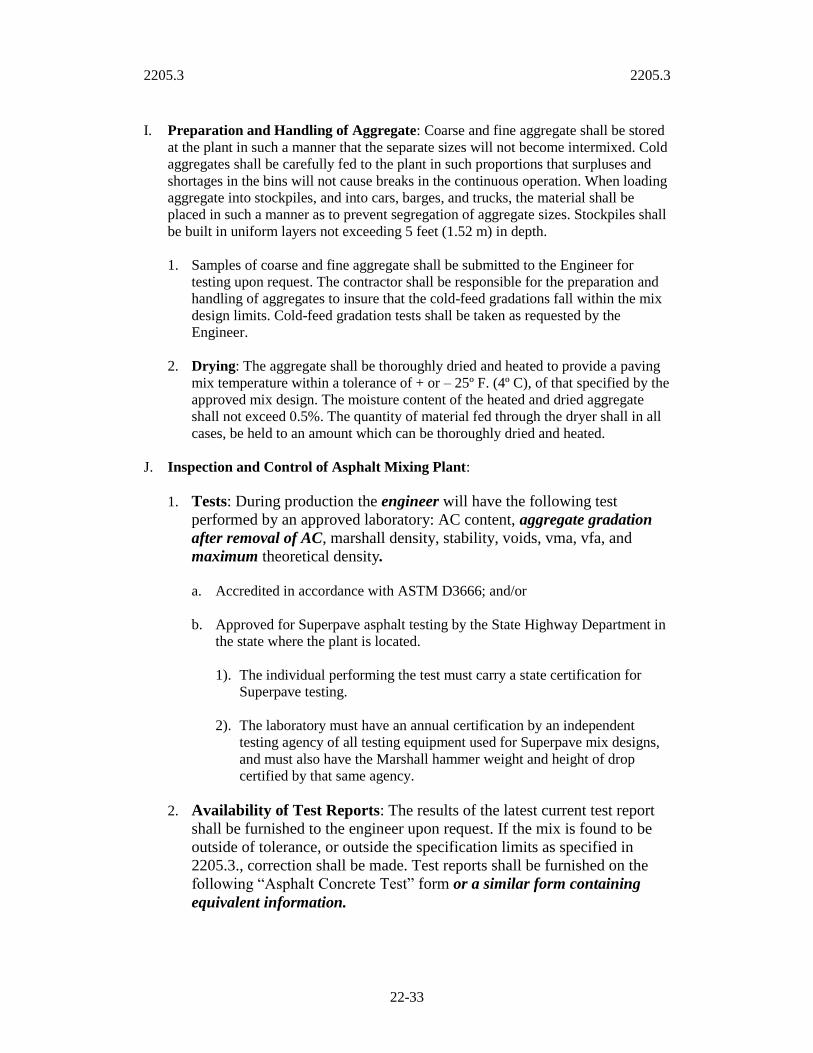
2205.3 2205.3
22-33
I. Preparation and Handling of Aggregate: Coarse and fine aggregate shall be stored
at the plant in such a manner that the separate sizes will not become intermixed. Cold
aggregates shall be carefully fed to the plant in such proportions that surpluses and
shortages in the bins will not cause breaks in the continuous operation. When loading
aggregate into stockpiles, and into cars, barges, and trucks, the material shall be
placed in such a manner as to prevent segregation of aggregate sizes. Stockpiles shall
be built in uniform layers not exceeding 5 feet (1.52 m) in depth.
1. Samples of coarse and fine aggregate shall be submitted to the Engineer for
testing upon request. The contractor shall be responsible for the preparation and
handling of aggregates to insure that the cold-feed gradations fall within the mix
design limits. Cold-feed gradation tests shall be taken as requested by the
Engineer.
2. Drying: The aggregate shall be thoroughly dried and heated to provide a paving
mix temperature within a tolerance of + or – 25º F. (4º C), of that specified by the
approved mix design. The moisture content of the heated and dried aggregate
shall not exceed 0.5%. The quantity of material fed through the dryer shall in all
cases, be held to an amount which can be thoroughly dried and heated.
J. Inspection and Control of Asphalt Mixing Plant:
1. Tests: During production the engineer will have the following test
performed by an approved laboratory: AC content, aggregate gradation
after removal of AC, marshall density, stability, voids, vma, vfa, and
maximum theoretical density.
a. Accredited in accordance with ASTM D3666; and/or
b. Approved for Superpave asphalt testing by the State Highway Department in
the state where the plant is located.
1). The individual performing the test must carry a state certification for
Superpave testing.
2). The laboratory must have an annual certification by an independent
testing agency of all testing equipment used for Superpave mix designs,
and must also have the Marshall hammer weight and height of drop
certified by that same agency.
2. Availability of Test Reports: The results of the latest current test report
shall be furnished to the engineer upon request. If the mix is found to be
outside of tolerance, or outside the specification limits as specified in
2205.3., correction shall be made. Test reports shall be furnished on the
following “Asphalt Concrete Test” form or a similar form containing
equivalent information.

2205.3 2205.3
22-34
3. Frequency of Testing: For mixes 1-01 through 4-01, the tests listed in
paragraph 2205.3.J.1. shall be performed a minimum of once for every
3000 tons (2700 metric tons) of asphalt production KCMO (Feb 15, 2002)
3 except during initial startup, or whenever the production asphalt fails
one of the following conditions at which time they will be tested every
1000 tons (900 metric tons) until four consecutive tests show compliance
with the specifications::
a. Production void content measured at the plant discharge is 1% below
laboratory mix design void content, or more than 5% total void content.
b. Extracted gradation of the production asphalt exceeds the permissible
gradation variation for the mix type being produced.
c. Asphalt cement exceeds the content variation for the mix type being
produced.
4. Frequency of testing: For mixes 5-01 and 6-01, the tests listed in paragraph 1
shall be performed once per day of production, or every 1000 tons (900 metric
tons), whichever is less frequent except during initial startup; or whenever the
production fails one of the following conditions at which time they will be tested
every 500 tons (450 metric tons), or twice per day of production, whichever is
less frequent until 4 consecutive tests show compliance with the specifications:
a. Production void content measured at the plant discharge is less than 3% or
more than 5%
b. Extracted gradation of the production asphalt exceeds the permissible
gradation variation for the mix type being produced.
c. Production vma measured at the plant discharge is below the design
minimum vma.
d. Production vfa measured at the plant discharge is outside the allowable
range.
5. Redesign of Asphalt mixes: If four consecutive tests performed as described in
paragraph 3 or 4 above show noncompliance with the specifications as
enumerated in the subparagraphs of paragraph 3 or 4 above, production of that
type of asphalt will immediately cease, and may not be resumed until a new mix
design is submitted and approved, or the plant can demonstrate to the engineer an
ability to meet specifications. Resumption of asphalt production after a mix
redesign or failure of four consecutive tests to meet specifications will be treated
as a initial startup for testing purposes.
ASPLATIC CONCRETE TEST (Verified Mix Design)

2205.3 2205.3
22-35
Description:
APWA Type:
LAB I.D.:
Sample Date:
Sample I.D.:
Supplier:
ASTM C 136, C 117, D
544
*Uncompacted Behind paver
**total mix basis
***total aggregate basis
EXTRACTION DATA-ASTM D6307 Plant Setting** Sample*
%***
Aggregate Type %*** Aggregate Type %***
MARSHALL CHARACTERISTICS (ACCEPTANCE (CRITERIA)
Compaction Blows (average of 3 specimens), Circle one (50 Types A-D, 75 Types E-F)
Sample* Specifications
Stability, lbs (kg) Min AASHTO T 245
Flow, 1/100 in (mm) Max AASHTO T 245
% Voids 3-5
%VMA ___ min
% VFA
Density, pcf (kg/cu.m) ___ ASTM D 2726
Ratio (-) 75 um (No. 200) to % Eff. Binder
Max Theoretical Specific Gravity Gmm ___ ASTM D 2041
Bulk Spec. Gr. Of total Agg. Gsb ___ ASTC C 127 & 128
COMMENTS:
LOT DENSITY SHALL BE TIED TO THE LOT AND DATE (Laboratories shall conform to ASTM D 3666)
LOT
Belt Tons
Hot Mix Tons
Sieve Size Belt
Sample
Hot-Mix
Sample*
Single Point Job-
Mix Formula
Job-Mix Formula
Tolerances
25 mm (1”)
19 mm (3/4”)
12.5 mm (1/2”)
9.5 mm (3/8”)
4.75 mm (No.4)
2.36 mm (No.8)
1.18 mm (No.16)
600 um (No.30)
300 um (No.50)
150 um (No.100)
75 um (No.200)
2205.3 2205.6
22-36
2205.4 Asphalt Mixing Plant: Plants used by the Contractor for preparation of the
asphalt paving mix shall be approved by the KCMO Public Works Department according
to the Hot Mix Asphalt Quality Management Plan and conform to the following
requirements:
A. Field Testing Laboratory: The Contractor shall provide a laboratory building or
room at the plant site, for the exclusive use of the Engineer for performing tests,
keeping records, and making reports at such times as the Engineer is performing
those actions.
The Contractor shall also furnish necessary laboratory sieves and a powered shaker
device for sieve analysis, scales, ignition oven and supplementary equipment to make
aggregate sieve analysis, asphaltic concrete paving mixture analysis, and paving
mixture density tests.
B. The asphalt producer shall establish a quality control plan and shall maintain records.
The quality control plan will be reviewed and approved by the City.
2205.5 Transportation of Mix: The mix shall be transported to the job site in vehicles
with tight metal bottoms, clean of all foreign material which may affect the mix. If a
release agent is used, it must comply with State and Federal environmental regulations.
The dispatching of the vehicles shall be so scheduled that all materials delivered may be
placed in daylight unless the Engineer approves artificial light. Delivery of the material to
the paver shall be at a uniform rate and in an amount within the capacity of the paving
and compacting equipment.
Haul trucks shall be provided with covers of sufficient size and weight to completely
cover the truck bed to protect the load and to prevent cooling of the upper surface. Failure
to have the load completely covered shall be sufficient cause for rejection of the entire
load. The load shall remain covered until the truck is next in line to be unloaded. In no
case shall a load remain uncovered for more than 10 minutes before starting to use the
load. If for any reason there is a delay in completely using a load, the remaining part of
the load shall be recovered until it can be used. It shall be the responsibility of the
Contractor to inform all truck drivers of these provisions before starting work.
2205.6 Scales and Weighing of Vehicles: The vehicle's tare and gross weight shall be
established by actually weighing the vehicle on a certified scale. The tare weight will be
established at least twice each day. The vehicle, when establishing tare, shall be clean,
bed empty, fuel tanks filled and shall have all side and back boards in place.
A. Measurement by weight: Measurement will be made by weighing each truck load
on scales conforming to the requirements of 2205.6 B “Vehicle Scales.”
B. Vehicle Scales: Vehicle scales shall be approved by the engineer and shall conform
to the requirements specified herein. The specifications, tolerances, and other
technical requirements for weighing and measuring devices as recommended by the
National Conference on Weights and Measures and published in the National
Institute of Standards and Technology Handbook 44, Specifications, Tolerances, and

2205.3 2205.6
22-37
Other Technical Requirements for Weighing and Measuring Devices, and
supplements thereto or revisions thereof, shall apply to all vehicles scales used.

2205.6 2205.7
22-38
C. Scale acceptance shall be based on one of the following:
1. A valid certification or seal of approval by the Division of Weights and Measures
from the state.
2. A certification of calibration from a commercial scale service company showing
that the scale meets the requirements of these specifications. The contractor shall
furnish the certification of calibration to the Engineer.
D. Scale Calibration: Scales shall have been calibrated within the nine month period
prior to any material being delivered, or at any time the Engineer has cause to
question the accuracy of the scale. Scales shall meet the requirements of Accuracy
Class III L as defined in Handbook 44 (above).
Verification of a vehicle scale may be required by weighing a hauling unit on another
recently calibrated and certified scale.
If equipment to be weighed is of such length that all axles cannot be weighed
simultaneously, a level paved surface shall be provided permitting those axles not on
the scale platform to be supported by the paved surface. The approach shall be at
least as wide as the platform and of sufficient length to insure the level positioning of
vehicles during weight determinations. The weighing shall be performed with all
brakes released. If equipment to be weighed is equipped with an air bag suspension
unit on any axle, the equipment including semi-trailers or pup trailers shall be
weighed on vehicle scales of sufficient size to weigh all axles of the combination
simultaneously.
All cost incurred in obtaining a certification of calibration or verification shall be
borne by the contractor.
2205.7 Requirements for Asphalt Paving Equipment: All asphalt paving equipment
used by the Contractor shall meet the requirements of this section and shall be maintained
in acceptable mechanical condition. Equipment shall be serviced and lubricated away
from the paving site. Units that drip fuel, oil, grease or other fluids shall be removed from
the project until such leakage is corrected.
A. Pavers and Laydown Machines: Mechanical self-powered pavers shall be capable
of spreading the mix within the specified tolerances, true to the line, grade and crown
indicated on the plans.
Pavers shall be in good working condition, equipped with quick and efficient
steering devices and shall be capable of traveling both forward and in reverse.
They shall be equipped with hoppers and distributing screws that place the
mix evenly in front of the adjustable screeds. They shall be equipped with
either a vibrating screed or a tamping bar immediately preceding a static
screed. The paver shall be equipped with a shoe that will produce a joint
between laying strips having its face inclined at an angle of thirty degrees
(30°) from the vertical. This type joint shall be used with all asphaltic

2205.7 2205.7
22-39
concrete mixes. The shoe shall be designed in such manner that it will be
capable of beveling depths up to 4 inches (10.16 cm).
There shall be sufficient auxiliary attachments for the paving machine so that it may
be operated to lay the necessary width as determined in the field by the engineer.
Vibrating screed or tamp bars shall be provided for the full width of all paving
operations.
The screed shall include a strike-off device which is effective on mixes at workable
temperatures without tearing, shoving or gouging them, and which produces a
finished surface of an even and uniform texture. The screed shall be adjustable as to
the height and crown and shall be equipped with a controlled heating device for use
when required. However, for irregular width paving, hydraulic extensions without
tamping bars or a vibrating screed may be used only along the curb or outer edge of
pavement.
1. Automatic Screed Controls: The paver shall be equipped with and use an
approved system capable of automatically controlling the elevation and
transverse slope of the paver screed unless otherwise directed by the
engineer. An erected stringline, traveling stringline or other approved
device operating on the roadbed being paved or the surface of the
previously placed la ne shall be used to establish the grade reference. The
grade reference device shall operate on either or both sides of the paver as
required and shall be capable of maintaining the desired transverse slope
regardless of changes in the screed elevation. In the event of failure of the
automatic screed control system, the contractor will be permitted to
continue placing the asphaltic concrete mix for the rest of the day in
which the failure occurred. The contractor will not be permitted to
continue operations without using automatic screed controls unless
permission has been granted by the engineer on each succeeding day
following the failure.
2. The traveling stringline shall be constructed in such a manner that it does not
vibrate or cause the sensor to make erroneous readings during the laydown
operation. The length of the beam to be used shall be approved by the Engineer
and shall be between 20 feet and 40 feet (6.1 and 12.2 m).
3. The use of the automatic screed control devices on asphalt pavers will not be
required for paving small irregular areas, entrances, approaches, or side street
connections.
4. Automatic screed control devices will be required for matching the joint with all
previously laid strips, except for those areas noted above.
B. Rollers: Compaction equipment shall consist of vibratory steel wheel, static steel
wheel and pneumatic-tired rollers unless otherwise directed by the engineer. They
shall be self-propelled and equipped with such controls that starting, stopping and
reversing direction can be accomplished without displacing the hot asphaltic concrete
pavement. Compaction equipment shall be in good working condition.
2205.7 2205.7
22-40
Rollers shall be equipped with adjustable scrapers to keep the wheel surfaces clean
and with efficient means of keeping them wet to prevent mixes from sticking. The
roller surfaces shall have no flat areas, openings or projections that will mar the
surface of the pavement.
1. Steel-Wheeled Rollers: Steel-Wheeled Rollers shall be vibratory or static two-
axle tandem rollers. Vibratory rollers shall develop contact pressure of 250 to
350 pounds per inch of width (45 to 62.5 kg per cm of width) (vibratory mode) or
150 to 180 pounds per inch of width (26.8 to 32 kg per cm of width) (static
mode). Static rollers shall be an 8 to 12 ton roller. The weight of the roller will
be varied, by order of the engineer, to obtain contact pressures that will result
in the required density.
2. Pneumatic-Tired Rollers: Pneumatic-tired rollers shall consist of two
axles on which are mounted an odd number of pneumatic tired wheels
of equal size and diameter. The roller shall have at least nine pneumatic-
tired wheels mounted in such a manner that the rear group of wheels will
not follow in the t racks of the forward group, but shall be spaced to give
essentially uniform coverage with each pass. There shall be a minimum
of ¼ inch (0.636cm) overlap in the tracking between the forward and
rear wheels. Axles shall be mounted in a rigid frame provided with a
loading platform or body suitable for ballast loading. Tires shall be smooth
and inflated to 90 p.s.i. (620 kPa). Construction of the roller shall be such
that each wheel is loaded to a minimum of 2,300 pounds (1043 kg). Wheel
loadings may be varied by order of the engineer to obtain contact
pressures that will result in the required density.
3. Trench Rollers: Trench rollers shall have an auxiliary wheel that operates
outside the area to be compacted at such a distance from the pavement edge as to
cause no damage thereto. It shall be mounted upon an axle that is adjustable in
height. The auxiliary wheel shall be kept in adjustment so that the compression
wheels will develop a smooth, compacted surface true to crown and grade.
The contact pressure of the compression wheels shall be from 250 to 350 pounds
per inch of width (45 to 62.5 kg per cm of width).
4. In lieu of the above requirements pertaining to non-vibratory compaction
equipment, consideration will be given to use other types of equipment that are
capable of producing equivalent results consistent with the requirements of the
specifications.
C. Pressure Distributor: The pressure distributor shall meet the requirements of
Section 2204.5 entitled "Pressure Distributor."
D. Hand Tools: The Contractor shall provide sufficient lutes, rakes, shovels, tamping
tools and other equipment as required to produce results consistent with the
specifications.

2205.7 2205.8
22-41
2205.8 Construction Requirements:
A. Preparation of the Area to be Paved: The area to be paved shall be true to line and
grade, and shall have a properly prepared surface prior to the start of the paving
operations. It shall be free from all loose or foreign material.
Where a base is rough or uneven, a leveling course shall be placed and properly
compacted before the placing of subsequent courses.
When leveling course is not required, all depressions and other irregularities shall be
patched or corrected, and the work approved by the Engineer before the paving
operation begins.
The area to be paved shall be primed or tacked uniformly in accordance with the
provisions of Section 2204 entitled "Prime and Tack Coat".
The surfaces of curbs, gutters, vertical faces of existing pavements and all structures
in actual contact with asphalt mixes shall be painted with a thin, complete coating of
asphaltic material to provide a closely bonded, watertight joint.
B. Weather Limitations: When the moisture of the aggregate in the stockpile or from
the dryer interferes with the quality of mix production, or with normal plant
operations, or when pools of water are observed on the surface to be paved, the
mixing and placing of hot-mix asphalt will not be permitted without the permission
of the Engineer.
Hot Mix asphalt paving shall not be mixed or placed when the ambient air or base
temperature is below 40º F (4.4º C), or when there is frost in the subgrade or any
other time when weather conditions are unsuitable for the type of material being
placed without expressed approval of the Engineer.
Asphalt mix laydown temperatures and rolling times shall conform to the following
table:
Minimum Laydown Temperature
Base Temp. 1-1/2” 2” 3” and Greater 40-50º F (4.4-10º C) 300º F (149º C) 285º F (141º C) 275º F (135º C)
50-60º F (10-16º C) 295º F (146º C) 280º F (138º C) 270º F (132º C)
60-70º F (16-21º C) 285º F (141º C) 275º F (135º C) 265º F (129º C)
70-80º F (21-27º C) 280º F (138º C) 270º F (132º C) 265º F (129º C)
80-90º F (27-32º C) 270º F (132º C) 265º F (129º C) 260º F (127º C)
90º+ F (32º+ C) 265º F (129º C) 260º F (127º C) 255º F (124º C)
Rolling Time 12 minutes 15 minutes 15 minutes
Regardless of the temperature, final acceptance of the asphalt mat shall be based on
density determined in accordance with section 2205.8 (E). Rolling times shown are
maximum times during which target density must be achieved.
C. Spreading and Finishing: The spreading and finishing of each course shall be to the
thickness and width indicated on the plans or Special Provisions. The thickness of
individual layers shall not exceed the following for the respective type of mixture.

2205.8 2205.8
22-42
The suggested minimum lift thickness shall be three times the nominal maximum
size of the mix. Nominal maximum is defined as the first sieve size larger than the
sieve which retains at least 10% of the aggregate by weight.
Asphalt Type Max. Compacted Lift Thickness
Type 1-01 6" (150 mm)
Type 2-01 4" (100 mm)
Type 3-01 3" (76 mm)
Type 4-01 2" (50 mm)
Type 5-01 4” (100 mm)
Type 6-01 3” (76 mm)
Spreading and finishing shall be conducted in the following manner:
1. Mechanical Pavers: The base and surface courses shall be spread and struck-off
with a mechanical paving machine meeting the requirements of Section 2205.7A
entitled "Pavers and Laydown Machines." The paving machine shall be operated
so that the material does not accumulate and remain along the sides of the
receiving hopper. The wings of the spreader hopper shall not be emptied
(flipped) between truck loads.
a. Equipment which leaves tracks or indented areas which cannot be corrected
in normal operation, or which produces other permanent blemishes or fails to
produce a satisfactory surface, shall not be used. The screed auger shall be
operated approximately ¾ full and the hopper conveyor shall not be allowed
to run out of material during the paving operation.
b. Longitudinal joints and edges shall be constructed to true lines. Lines for the
paver to follow in placing individual lanes will be established parallel to the
centerline of the proposed roadway. The paver shall be positioned; and
operated to follow closely the established line.
c. Sufficient trucks shall be used to continuously supply asphalt to the paver.
Delays in the paving operation shall be kept to a minimum.
d. The Contractor shall make every effort to minimize the number of passes
heavy equipment makes over uncompleted roadway sections.
e. When using pavers in echelon, the second paver shall follow the edge of the
material placed by the first paver. The length of each laydown pass shall be
limited, depending on weather conditions, to assure a hot joint and obtain
proper compaction.
f. As soon as the first load of material has been spread, the texture of the
unrolled surface shall be checked to determine its uniformity. Segregation of
materials shall not be permitted. If segregation occurs, the spreading
operation shall be immediately suspended until the cause is determined and
corrected.
2205.8 2205.8
22-43
g. Transverse joints in succeeding courses shall be offset at least 2 feet (0.6 m).
Longitudinal Joints shall be offset at least 6 inches (150 mm). The
longitudinal joints shall be laid out so that the surface joint is under the lane
markings where possible.
h. Any irregularities in alignment left by the paver shall be corrected directly
behind the machine. Immediately after the correction, the edge of the
course shall be thouroughly compacted by tamping. Distortion of the
pavement during this operation shall be avoided.
i. Edges against which additional pavement is to be placed shall be placed on a
30º (2:1) bevel, or as specified by the engineer. Any irregularities in the
surface of the pavement course shall be corrected directly behind the paver.
Excess material forming high spots shall be removed by a shovel or lute.
Indented areas shall be filled with hot mix and smoothed. Broadcasting of
material shall not be permitted.
2. Hand Spreading: In small areas where the use of mechanical finishing
equipment is not practical, the mix may be spread and finished by hand. The
material shall be distributed uniformly to avoid segregation of the coarse and fine
aggregate. Broadcasting of material shall not be permitted. During the spreading
operation, all material shall be thoroughly and uniformly distributed by lutes or
rakes. Material that has formed into lumps and does not break down readily shall
be removed. Following placing and before rolling, the surface shall be checked
with templates and straightedges and all irregularities corrected.
D. Compaction:
1. General: A minimum of three rollers shall be used for compacting mixes unless
otherwise approved by the engineer. These rollers shall meet the requirements of
Section 2205.7B entitled "Rollers." Additional rollers shall be used as necessary
to provide specified pavement density.
Immediately after spreading, each course of the pavement mixture shall be
compacted by rolling. The initial or “breakdown” rolling shall be
accomplished with a steel-wheeled roller meeting the requirements of
2205.7.B.1. and shall take place as closely behind the laydown machine
as the temperature and condition of the mat will allow. The pneumatic-
tired roller shall be used to knead and compact the pavement mixture
following the initial rolling and preceding the final rolling. Care shall be
exercised in the use of the pneumatic-tired roller to ensure that the
pavement mixture is sufficiently cooled to avoid “picking up” of the
mixture on the tires of the roller, and also to ensure that the pneumatic-
tired rolling is completed before the mixture becomes too cool to allow
satisfactory finish rolling. Final, or finish rolling shall be done with a
steel- wheeled roller. The sequence of rolling operations may be changed
with the approval of the engineer. All rolling shall be longitudinal, starting
near the edge of the pavement and progressing toward the center,
overlapping on successive trips by not less than one-third (1/3) and no
2205.8 2205.8
22-44
more than one-half (1/2) the width of the roller. Alternate trips of the
roller shall be of slightly different lengths.
The motion of the roller shall be slow enough at all times to avoid displacement
of the hot mixture. The initial compaction roll shall be accomplished with the
roller drive wheel leading the tiller wheel. Any displacement occurring as a result
of reversing the direction of the roller, or from any other cause, shall be corrected
immediately by the use of rakes and fresh mixture when required. To prevent
adhesion of the mixture to the roller, the wheels shall be kept properly moistened,
but excess water will not be permitted.
The surface of the mixture after compaction shall be smooth and true to
established section and grade. Any surface which is segregated, or is in any way
defective, shall be removed and replaced with fresh hot mixture at the
Contractor's expense, and shall be immediately compacted to conform with the
surrounding area.
2. Rolling Procedure:
a. Thin Layers (Lifts): When placing a thin lift (less than 2 in.[50 mm]
compacted thickness) in single-lane width or full width, the mixture should
be rolled in the following sequence:
1). Transverse joint.
2). Outside edge.
3). Breakdown rolling, beginning on the low side.
4). Intermediate rolling; same procedure as Step 3.
5). Finish rolling.
b. When paving a thin lift in echelon, or when abutting a previously placed lane
or other lateral restraint, the mixture should be rolled in the following
sequence:
1). Transverse joint.
2). Longitudinal joint.
3). Outside edge.
4). Breakdown rolling, beginning on the low side.
5). Intermediate rolling; same procedure as Step 4.
6). Finish rolling.

2205.8 2205.8
22-45
c. Thick Layers (Lifts): When placing a thick lift (2 in. [50 mm] or more
compacted thickness) in single-lane width or full width, the mixture should
be rolled in the following sequence:
1). Transverse joint.
2). Breakdown rolling, beginning 12 to 15 in.(300 to 380 mm) interior to the
lower unsupported edge. The return pass shall be made with the edge of
the roller 3 inches (76 mm) exterior to the unsupported edge of the
pavement.
3). Breakdown rolling of outside edge. Repeat the process described in Step
2 above on the other longitudinal edge.
4). Intermediate rolling, beginning on the low side.
5). Finish rolling.
d. When paving a thick lift in echelon, or when abutting a previously placed
lane or other lateral restraint, the mixture should be rolled in the following
sequence:
1). Transverse joint.
2). Longitudinal joint.
3). Breakdown rolling, beginning at the longitudinal joint.
4). Intermediate rolling, beginning on the low side.
5). Finish rolling.
e. When paving in echelon, 2-3 inches (5.08-7.62 cm) of the first mat shall be
left unrolled, and rolled when the joint between the lanes is rolled and after
the 2nd mat is placed. Edges shall not be exposed more than fifteen minutes
without being rolled. Particular attention shall be given to the construction of
transverse and longitudinal joints in all courses.
f. In laying a surface mix adjacent to any finished area, it shall be placed
sufficiently high so that, when compacted, the finished surface will be true
and uniform. Where the grade is slight a level will be used to insure drainage
to the desired outlet.
3. Transverse joints: When the transverse joint is next to an adjoining lane, the
first pass shall be made with a static steel-wheeled roller moving along the
longitudinal joint for a few feet. The surface will then be checked with a
straightedge and corrections shall be made if necessary. The joint then shall be
rolled transversely, with 6 in.(150 mm) of the drum width on the newly laid
material. This operation shall be repeated with successive passes, each covering
an additional 6 to 8 in.(150 to 200 mm) of the new mat, until the entire width of a

2205.8 2205.8
22-46
drive roll is on the new mixture. During transverse rolling, wooden boards of the
proper thickness should be placed at the edge of the pavement to give the roller a
surface to drive on once it passes the edge of tile Mat. if boards are not used,
transverse rolling must stop 6 to 8 in. (150 to 200 mm) short of the outside edge
to prevent damaging it, and the edge must be compacted later during longitudinal
rolling. Transverse joints shall be carefully constructed and thoroughly
compacted to provide a smooth riding surface. If the joint has been distorted, it
shall be trimmed to a line. The joint face shall be tacked before the fresh material
is placed against it.
4. Longitudinal joints: Longitudinal joints shall be rolled directly behind the
paving operation. The edge to be joined shall be tack coated. The paver screed
shall be set to overlap the first mat by 1-2 inches (25-50 mm). The elevation of
the screed above the surface of the first mat should be equal to the amount of
roll-down expected during compaction of the new mat. For large aggregate
mixes, the coarse aggregate in the material overlapping the cold joint should be
carefully removed and wasted, leaving only the finer portion of the mixture to be
pressed into the compacted lane at the time the joint is rolled. For mixes with
smaller coarse aggregate, such as surface courses, the overlapping material
should be pushed with a lute into a hump over the joint area prior to compaction.
5. Edges: The edges of the pavement shall be rolled concurrently with or
immediately after rolling the longitudinal joint. Care shall be exercised in
consolidating the material along the entire length of the edges. Before
compaction, the materials along the unsupported edges shall be slightly
elevated with a tamping tool or lute. This will permit the full weight of
the roller wheel to bear on the material to the extreme edges of the mat.
In rolling pavement edges, roller wheels shall extend approximately two
inches (5cm) beyond the pavement edge, provided lateral displacement is
not excessive.
6. Breakdown Rolling: Breakdown rolling shall immediately follow the rolling of
the longitudinal joint and edges. Rollers shall be operated as close to the paver as
necessary to obtain adequate density without causing undue displacement. The
breakdown roller shall be operated with the drive wheel nearest the laydown
machine. Exceptions may be made by the Engineer when working on steep
slopes or super-elevated curves.
7. Intermediate Rolling: Pneumatic-tired rollers as specified in Section 2205.7B
entitled "Rollers" shall be used for intermediate rolling. The intermediate rolling
shall follow the breakdown rolling as closely as possible and while the paving
mix is still of a temperature that will result in maximum density from this
operation. Pneumatic-tired rolling shall be continuous after the initial rolling until
all of the mix placed has been compacted to the required density. Turning of
pneumatic-tired rollers on the hot paving mix which causes displacement shall
not be permitted.
8. Finish Rolling: The finish rolling shall be accomplished while the material is
still warm enough for the removal of roller marks. All roller marks shall be

2205.8 2205.10
22-47
removed by the finish rolling operation. All rolling operations shall be conducted
in close sequence.
9. In places inaccessible for the operation of standard rollers as specified,
compaction shall be performed by trench rollers or others meeting the
requirements of Section 2205.7B entitled "Rollers." The trench roller shall be
operated until the lift is thoroughly compacted. Hand tamping, manual or
mechanical, may be used in such areas, if such operations will give the required
density.
E. Density and Surface Requirements: The completed asphalt concrete paving shall
have a density equal to or greater than 95% for Type 1-01 and 5-01 Asphalt Concrete
Base and 96% for Types 2-01, 3-01, 4-01, 5-01 and 6-01 Asphalt Concrete Surface.
Density is based on laboratory specimens prepared as specified in Section 2205.3B
entitled "Mix Design Criteria" and made from plant mix conforming to the job mix
formula. Density testing shall conform to ASTM D 2950 or ASTM D 2726 or D
1188.
If cores are used to determine density, one or more tests (one test equals three cores)
will be taken for each tonnage lot and averaged to determine acceptance. Two cores
will be taken from the lane being paved, and one core centered on the longitudinal
joint with the adjoining lane. The Engineer will mark the locations of all cores. The
compacted surface shall be 0-1/4 in. (0-6 mm) above the edge of curb. All
unsatisfactory work shall be repaired, replaced or corrected. The surface of the final
course shall be of a uniform texture and conform to line and grade shown on the
plans.
The field control density will be based on the density of plant produced mix
compacted in a laboratory in accordance with Section 2205.3 (C).
2205.9 Method of Measurement: Asphaltic concrete base, asphaltic concrete surface, or
asphaltic concrete base and surface may be included in the proposal as separate items, or
as a single item, and may be measured by one of the following:
A. Per square yard (square meter) or tenth part thereof for the specified depth.
B. Per ton (metric ton) or tenth part thereof.
C. If pavement smoothness is required in the proposal, pay adjustments will apply to the
traffic lane design driving width only in accordance with Section 2211.
2205.10 Basis of Payment: Asphaltic Concrete Surface, Asphaltic Concrete Base, or
Asphaltic Concrete Base and Surface whether used for paving, patching, or leveling
courses will be paid for by one of the following:
A. Contract unit bid price.
B. Contract lump sum bid price.
C. Testing described in Section 2205.3 paragraph I is subsidiary to the price bid for
asphalt unless otherwise provided for in the contract.
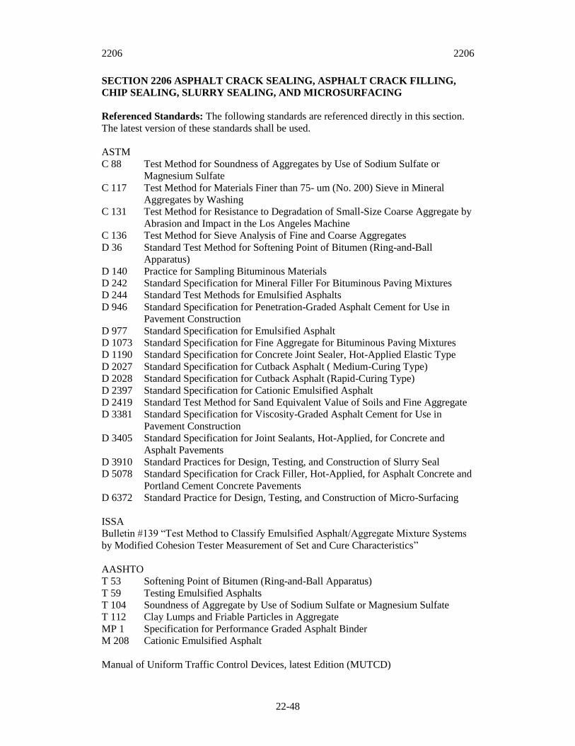
2206 2206
22-48
SECTION 2206 ASPHALT CRACK SEALING, ASPHALT CRACK FILLING,
CHIP SEALING, SLURRY SEALING, AND MICROSURFACING
Referenced Standards: The following standards are referenced directly in this section.
The latest version of these standards shall be used.
ASTM
C 88 Test Method for Soundness of Aggregates by Use of Sodium Sulfate or
Magnesium Sulfate
C 117 Test Method for Materials Finer than 75- um (No. 200) Sieve in Mineral
Aggregates by Washing
C 131 Test Method for Resistance to Degradation of Small-Size Coarse Aggregate by
Abrasion and Impact in the Los Angeles Machine
C 136 Test Method for Sieve Analysis of Fine and Coarse Aggregates
D 36 Standard Test Method for Softening Point of Bitumen (Ring-and-Ball
Apparatus)
D 140 Practice for Sampling Bituminous Materials
D 242 Standard Specification for Mineral Filler For Bituminous Paving Mixtures
D 244 Standard Test Methods for Emulsified Asphalts
D 946 Standard Specification for Penetration-Graded Asphalt Cement for Use in
Pavement Construction
D 977 Standard Specification for Emulsified Asphalt
D 1073 Standard Specification for Fine Aggregate for Bituminous Paving Mixtures
D 1190 Standard Specification for Concrete Joint Sealer, Hot-Applied Elastic Type
D 2027 Standard Specification for Cutback Asphalt ( Medium-Curing Type)
D 2028 Standard Specification for Cutback Asphalt (Rapid-Curing Type)
D 2397 Standard Specification for Cationic Emulsified Asphalt
D 2419 Standard Test Method for Sand Equivalent Value of Soils and Fine Aggregate
D 3381 Standard Specification for Viscosity-Graded Asphalt Cement for Use in
Pavement Construction
D 3405 Standard Specification for Joint Sealants, Hot-Applied, for Concrete and
Asphalt Pavements
D 3910 Standard Practices for Design, Testing, and Construction of Slurry Seal
D 5078 Standard Specification for Crack Filler, Hot-Applied, for Asphalt Concrete and
Portland Cement Concrete Pavements
D 6372 Standard Practice for Design, Testing, and Construction of Micro-Surfacing
ISSA
Bulletin #139 “Test Method to Classify Emulsified Asphalt/Aggregate Mixture Systems
by Modified Cohesion Tester Measurement of Set and Cure Characteristics”
AASHTO
T 53 Softening Point of Bitumen (Ring-and-Ball Apparatus)
T 59 Testing Emulsified Asphalts
T 104 Soundness of Aggregate by Use of Sodium Sulfate or Magnesium Sulfate
T 112 Clay Lumps and Friable Particles in Aggregate
MP 1 Specification for Performance Graded Asphalt Binder
M 208 Cationic Emulsified Asphalt
Manual of Uniform Traffic Control Devices, latest Edition (MUTCD)

2206 2206.2
22-49
2206.1 Summary: This section includes minor pavement patching and crack cleaning
and sealing, construction of asphalt seal-coat, microsurfacing and slurry seal, complete,
in place, at the locations specified in the Special Provisions and as directed by the
Engineer.
2206.2 Crack Sealing/Filling:
A. Crack Sealant Application: Material used for crack sealing shall be a modified
asphalt product selected to be compatible with the environment of application and
found to meet the criteria of one of the following specifications, ASTM D 1190 or
ASTM D3405 with a modified resilience value between 30 and 60 percent, or
material meeting the requirements of ASTM D 5078. Crack Sealing shall be
understood to be the process of placing an asphaltic material into and/or above
working cracks to prevent the intrusion of surface water and/or incompressibles into
the crack. A working crack shall be understood to correspond to cracks that sustain
more than 0.1 inches (2.5 mm) movement during the course of the year.
B. Crack Filling Application: Material used for crack filling shall be an
viscositygraded AC-20 asphalt product meeting the criteria of ASTM D 3381 Table
1, a penetration-graded asphalt product having a penetration number in the range of
85-100 measured in accordance with ASTM D 946, or material meeting the criteria
of ASTM D-5078. Crack filling material may contain polyester or polypropylene
fibers. Material satisfying the criteria of a crack sealant may also be used as a crack
filling material. Crack filling shall be understood to be the process of placing an
asphaltic material into non-working cracks to substantially reduce water infiltration
and reinforce adjacent cracks. Crack filling materials shall not be used for sealing
pavements in preparation for an overlay.
C. Equipment:
1. Router: This machine shall be an impact cutterhead with a minimum of 6
tungsten-carbide cutters. The router blades shall be driven with a minimum 25-hp
gasoline engine.
2. Compressor: The compressor shall be a two-stage compressor rated as a
minimum 40 CFM unit capable of delivering compressed air to the nozzle at a
minimum pressure of 100 psi. The compressor shall be equipped with a filter trap
to eliminate oil and moisture from the air line.
3. Hot-Air Lance (HCA): The hot air lance shall be capable of delivering super-
heated air at an exit temperature in excess of 1500oF and at a velocity in excess
of 1000 ft/sec against the side walls of the crack. The hose shall be wrapped with
reflective tape to keep hoses together and to protect worker in low light
situations.
2206.2 2206.2
22-50
4. Melter/Applicator:
a. The melting pot shall consist of double-boiler type jacket and shall be
equipped with a full sweep agitator that promotes proper mixing and
maintains uniform heat distribution throughout the melting pot. The melting
pot shall have sufficient capacity of the heat transfer oil reservoir that heat
transfer oil is able to come in contact with 100 percent of the outside area of
the jacket. The melting pot shall be equipped with a drain plug to permit 100
% of the heat transfer oil to drain from the boiler. The heat transfer oil shall
consist of ISO grade 68.
b. The heat transfer oil shall be heated with a properly sized vapor fuel LP or
diesel fuel burner. The heat shall be applied directly to the bottom of the heat
transfer tank. The burner shall be lit by an electric spark igniter controlled by
a sensor, which detects a lack of burn or ignition and subsequently shuts
down the fuel supply. The unit must be capable of starting at ambient
temperature and bringing the sealant up to the required applications
temperature within the period of approximately one hour while continuously
agitating and recirculation the sealant. The unit shall have the capability of
independently monitoring both the transfer oil and melting pot temperatures.
The unit shall be capable of heating a variety of application materials within
a range of temperatures between 200oF (93.3oC) and 425oF (218.3oC). The
sealant should not be heated to a temperature in excess of that specified by
the manufacturer.
c. The agitator and material pump shall be actuated by hydraulic motors driven
by a single, pressure-compensated hydraulic pump. Hydraulic fluid should
only be pumped to the agitator or material pump motor on demand.
d. The sealant shall be applied to the pavement through an application system
consisting of a pressure feed hose and wand. The hose shall be specially
manufactured to handle liquid asphalt products up to 450oF (218oF) at 350
psi (2400 kPa) working pressure. The hose shall not be less than 15 feet in
length. The hand wand shall be constructed of steel of sufficient strength to
withstand normal day-to-day operations. Material flow through the ward
shall be controlled with a toggle switch. A squeegee shall be used to
distribute the asphalt evenly and uniformly in the recommended
configuration.
e. All equipment shall be in good working order, as determined by the
Engineer, on a day-to-day basis. The Engineer shall not be responsible for
payment of labor or rental charges on days when the equipment is not in
good working order.
D. Preparation:
1. Crack sealing shall be limited to working, transverse cracks that are more than
1/4-inch (6mm) in width. Cracks 1/4- to 5/8-inches (6mm to 16 mm) in width
requiring sealing shall be routed to 5/8-inches (16 mm) in width. Cracks 5/8- to
1-inch (16mm to 25 mm) in width requiring sealing do not require routing but
2206.2 2206.2
22-51
shall be thoroughly cleaned and sealed. Cracks shall be sealed using either the
Standard Reservoir and Flush or Standard Recessed Band-Aid configurations.
Cracks greater than 1-inch (25 mm) in width shall be filled with either an
emulsion slurry and sand, widened and backfilled with Hot-Mix Asphalt (HMA),
or repaired in a manner approved by the Engineer. Cracks requiring filling do not
require any routing but simply thorough cleaning. Cracks shall be filled using
either the Simple Band-Aid, Simple Flush Fill, or Capped Configurations.
2. Cracks shall be cleaned free of all deleterious materials, including any old
sealant; incompressibles; and organic material. The crack shall be free of any
standing water and any moisture along the sidewalls of the crack as evidenced by
a darker color than the adjacent pavement. This shall be accomplished in one of
three manners: wire-brushing – where the crack channels are cleaned with a
mechanical wire brush followed by high-pressure compressed air; hot air
blasting – where the crack channels are cleaned, heated, dried with hot
compressed air (HCA) lance connected to a high pressure air compressor; or
high-pressure air blasting – where the crack channels are cleaned with high-
pressure compressed air. Pavement cracks to be sealed or filled shall be cleaned
and dried using one of the methods described previously within 10 minutes of the
application of the sealer/filler. Equipment for the two operations should be kept
in a compact configuration such that not more than 50 feet separates equipment
required by the two operations. Additionally, not more than 10 minutes time shall
passed between the cleaning of a crack and the filling of the crack with the
appropriate sealing/filling material.
E. Installation:
1. Sealer/filler materials should not be applied when the pavement surface is wet or
when the pavement temperature is less than 40oF (4.5oC) without the use of hot
air blasting or the approval of the Engineer.
2. Sealant/Crack filler should be applied to fill the crack from the bottom to the top
in order to prevent air bubbles from forming and creating a point of weakness in
the sealant. Upon application, hot sealant/filler material should not make a
hissing or popping noise indicative of moisture in the crack. Noises of this kind
should indicate that additional drying of the crack is necessary in order to
facilitate proper bonding of the material to the sidewalls of the crack. Application
of the sealant/filler material shall be made in such a way as to completely fill the
crack and provide enough excess to facilitate completion of the seal/fill
consistent with the configuration selected. The use of a squeegee or applicator
disk to shape the application material to conform with one of the material
placement configurations shown on Figure 1 is required. Care shall be taken not
to place any sealant/filler material on top of any pavement markings, manholes,
or drainage castings. The Contractor shall be responsible to prevent tracking of
the sealant/filler material onto the adjacent pavement surfaces to the satisfaction
of the Engineer.
3. The manufacturer’s technical representative shall be notified by the Contractor
and shall be present during the initial installation. Prior to beginning the work,
the Contractor will be required to demonstrate to the satisfaction of the Engineer

2206.2 2206.2
22-52
and the manufacture’s representative his ability to apply the material in
accordance with the manufacture’s specifications. Operations and procedures
which are considered by the Engineer as detrimental to the effectiveness of the
material will not be permitted.
Material placement configurations for AC crack treatments.
Figure 1
2206.2 2206.3
22-53
2206.3 Improved Street Chip Seal:
A. Description: This work shall consist of the application of a thin, uniform layer of
emulsified asphalt to the existing pavement surface in order to universally seal cracks
from the intrusion of surface water. Cover aggregate shall then be uniformly
distributed upon the asphalt layer and seated in place with the use of a rubber-tired
roller. Any excess aggregate material shall be removed, leaving a durable wearing
surface.
B. Material Requirements:
1. Emulsified Asphalt:
a. The asphaltic sealant material applied to the roadway surface shall consists of
a rapid-setting emulsified asphalt either an anionic RS-2 meeting the criteria
of ASTM D-977 or a cationic CRS-2 meeting the criteria of ASTM D-2397.
These materials may be modified with rubber products in the form of liquid
latex, styrene-butidane-rubber, or styrenebutidane-styrene to enhance
performance of the material as approved by the Engineer. If a polymer-
modified material is used, the emulsified asphalt shall meet the additional
specification criteria required by the Engineer.
b. A sample of the emulsified asphalt may be taken from any of the distributors
or delivery tankers on the job site. Failure of the emulsified asphalt to meet
the material specification criteria at the time of application shall require the
Contractor, at his own expense, to correct all unsatisfactory areas. No
additional areas shall be sealed until correction has been make to the
satisfaction or the Engineer.
2. Cover Aggregate – Precoated Chips:
a. Materials: Aggregate materials shall consist of an approximately cubic and
uniformly-graded, hard, durable 100 percent crushed and washed limestone,
sandstone, lightweight aggregate, basalt/porphyry, granitic material, steel
slag, gravel, or chat. Chat is a by-product from the production of lead and
zinc from the area located in southwestern Missouri, northeastern Oklahoma,
and southeastern Kansas. Lightweight aggregate shall consist of expanded
shale. The application rates reported in these specifications is for the Bethany
Falls Limestone in the Kansas City area. The specific gravity of this material
is approximately 2.58
b. Physical properties required of the aggregate materials:
Los Angeles Abrasion (ASTM C 131) 35% loss (maximum)
Soundness using Mag. Sulfate (ASTM C88) 15% loss (maximum)
Total Shale, clay, coal, and lignite content 0.5% by weight (max)
Absorption 4.0% (max)
c. Gradation: Gradation of cover aggregates shall conform to the following
percentages:

2206.3 2206.3
22-54
Sieve Size Percent Passing
¾” (19mm) 100
½” (12.5mm) 90-95
3/8” (9.5mm) 30-50
No. 4 (4.75mm) 0-5
No. 8 (2.36mm) 0
d. Precoating of Chips: Aggregate chips shall be uniformly heated in a dryer until
surface dry. All material shall be free of moisture, dust, and lumps and shall be
approved by the Engineer prior to use. The aggregate chips shall then be pre-
coated with 0.9%+ 0.025% a liquid asphalt cement having a viscosity of 2000
poise, +20%. The asphaltic material and hot aggregate shall be measured
separately and accurately immediately before introduction into the mixer. Mixing
shall be accomplished at a temperature between 275oF (135oC) and 325oF
(1630C), sufficient to produce a thoroughly and uniformly coated aggregate. The
pre-coated chips shall be stockpiled at least 3 days prior to use.
3. Weighing: Weighing of cover aggregate shall be accomplished by the Contractor
on scales that he furnishes for the purpose of weighing the cover aggregate as
required in Section 2205.6 entitled “Scales and Weighing of Vehicles.” All loads
of cover aggregate will be weighed and evidenced by approved delivery tickets
showing the net weight in pounds (kilograms) for each load. Two copies of each
ticket shall accompany the load to the work site. Upon the load being
incorporated in the work, the Engineer will sign both copies and one of these
copies will be returned to the Contractor.
C. Spot Patching: Areas where base failure of the roadway has occurred, or where the
surface is broken out shall be repaired prior to the sealing operation. The failed
sections will be marked by the engineer, and shall be removed by sawing a neat
rectangular hole into the pavement. The failed material shall be removed without
damage to the adjacent pavement. Where base failures have occurred, the pavement
shall be removed to the subgrade which shall be corrected to the satisfaction of the
engineer prior to patching. Unstable material shall be overexcavated and replaced
with base materials meeting the requirements of Section 2202. All surfaces shall be
properly primed and tacked in accordance to Section 2204.
The prepared hole shall be patched with hot-mix asphaltic patching material by
placing in layers not to exceed 2 inches (5.08 cm); each layer being thoroughly
compacted before the next layer is placed. After the patching material is placed and
raked to a uniform surface, it shall be thoroughly compacted by rolling with a roller
meeting the requirements of Section 2205.7. The edges shall be well bonded with the
old surface. The completed patch shall be in the same plane as the existing pavement.
The asphaltic concrete used for patching at the different locations shall be as directed
by the Engineer and shall conform to one of the mixes as set out-in Section 2205.3.

2206.3 2206.3
22-55
D. Sealing:
1. Cleaning: After all holes and cracks have been repaired to the satisfaction of the
Engineer, and immediately before sealing the Contractor shall thoroughly clean
the area to be sealed with a mechanical pickup type sweeper to insure proper
adhesion of the new seal coat to the existing pavement. The street shall be dry
before applying the seal coat.
2. Sealing: After the street has been prepared as set forth above the Contractor shall
apply the emulsified asphalt by means of an approved distributor meeting the
requirements of Section 2204.5. Provisions shall be made by the Contractor to
properly protect the curbs and gutters from the asphaltic spray. Emulsified
asphalt shall be applied at a rate between 0.28 and 0.35 gallons per square yard
(1.27 and 1.58 Liters per square meter). The specific rate for each job will be
determined by the Engineer in the field. Immediately after the application of the
asphalt, the Contractor shall, by means of a self-propelled mechanical spreader,
apply a uniform layer of cover aggregate. This material shall be spread at the rate
specified by the Engineer. This rate shall be between 18 and 25 pounds per
square yard (9.7and 13.6 kg per square meter) of pre-coated limestone chips. The
application rate shall be set to prevent bleeding of the asphaltic material through
the cover aggregate. If material is spread on any area in excess of the amount
specified by the Engineer, the surplus shall be immediately removed and placed
elsewhere as directed. No payment will be made to the Contractor for the picking
up and redistribution of such excess. Hand spreading will be permitted only in
those areas not accessible to the mechanical spreader.
Immediately after spreading the cover aggregate, the entire surface shall be rolled
with multiple-wheel, pneumatic-type rollers meeting the requirements of Section
2205.7. Rolling shall be continued until a thoroughly compacted surface with a
uniform aggregate coverage has been obtained, a minimum of 6 passes. The
Engineer may require additional rollers if one roller cannot keep up with the
operations. The first pass of the rollers over the cover aggregate shall not exceed
3 miles per hour (5 km per hour). The rollers shall not exceed 5 miles per hour (8
km per hour) during any rolling operation.
Forty-eight hours after spreading the cover aggregate, the entire surface shall be
swept with a mechanical pickup type sweeper to remove any loose or excess
cover aggregate.
During the sealing operation as described above, the Contractor shall cooperate
with the Engineer in arranging a program and schedule of work so traffic may be
handled or routed around or through the section being sealed. Whenever possible,
the street will be closed; but when this is not possible, the sealing will be done in
strips while traffic is diverted to the balance of the street. No traffic will be
permitted on the sealed portion of the roadway until rolling is completed. All
traffic control signage shall conform to the MUTCD handbook for traffic control
in work zones.

2206.3 2206.4
22-56
When bleeding occurs or more material is required, additional cover aggregate
shall be spread as directed. As soon as the cover material has adhered to the
surface, and the emulsion is thoroughly cured all excess cover aggregate shall be
removed with a mechanical pickup type sweeper. This curing period is generally
48 hours, but may be adjusted by the engineer.
2206.4 Unimproved Street Chip Seal:
A. Description: This work shall consist of the application of a thin, uniform layer of
liquefied asphalt to the surface of the existing roadway which may either consist of
an existing surface of asphaltic concrete or a gravel-surfaced road. Cover aggregate
shall then be distributed uniformly upon the liquefied asphalt and seated in place with
the use of a rubber-tired roller leaving a durable wearing surface..
B. Requirements for Liquefied Asphalt Materials: Asphaltic materials used for the
sealing of unimproved streets shall be liquefied either by the introduction of a diluent
(cutback) or by emulsification. The particular grade of cutback material for use on a
particular roadway shall be determined by the Engineer. Cutback asphaltic materials
shall comply with the requirements of either ASTM D-2027 or ASTM D-2028. The
particular grade of emulsified asphalt material for use on a particular roadway shall
be determined by the Engineer. Anionic emulsified asphaltic materials shall comply
with the requirements for either a rapid or medium-setting emulsion as described in
ASTM D-977 while cationic emulsified asphaltic materials shall comply with the
requirements for either a medium or rapid-setting emulsion as described in ASTM D-
2397.
C. Requirements for Cover Aggregate Materials:
a. Aggregate materials shall consist of an approximately cubical and uniformly-
sized, hard, durable 100 percent crushed and washed limestone, sandstone,
lightweight aggregate, basalt/porphyry, granitic material, steel slag , gravel, or
chat. Chat is a by-product from the production of lead and zinc from the area
located in southwestern Missouri, northeastern Oklahoma, and southeastern
Kansas. Lightweight aggregate shall consist of expanded shale. Due to the
variation in specific gravities between these materials, the application rate will
need to be adjusted to reflect the change in specific gravity. The application rates
reported in these specifications is for the Bethany Falls Limestone in the Kansas
City area. The specific gravity of this material is approximately 2.58
b. Physical properties required of the aggregate materials:
Los Angeles Abrasion (ASTM C 131) 35% loss (maximum)
Soundness using Mag. Sulfate (ASTM C88) 15% loss (maximum)
Total Shale, clay, coal, and lignite content 0. 5% by weight (max)
Absorption 4.0% (max)
Aggregate chips applied to cutback asphalt shall be shown to have moisture content
less than 1 percent immediately prior to application. Aggregate chips applied to
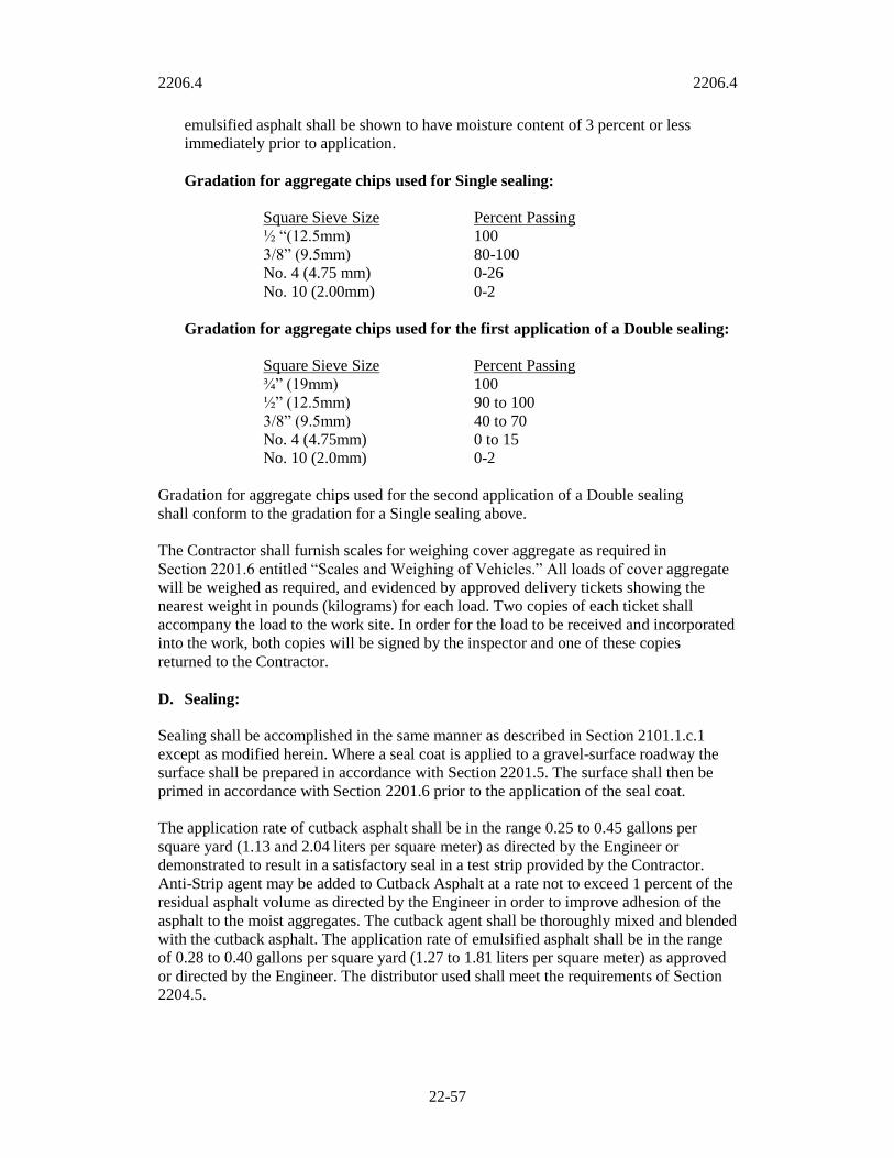
2206.4 2206.4
22-57
emulsified asphalt shall be shown to have moisture content of 3 percent or less
immediately prior to application.
Gradation for aggregate chips used for Single sealing:
Square Sieve Size Percent Passing
½ “(12.5mm) 100
3/8” (9.5mm) 80-100
No. 4 (4.75 mm) 0-26
No. 10 (2.00mm) 0-2
Gradation for aggregate chips used for the first application of a Double sealing:
Square Sieve Size Percent Passing
¾” (19mm) 100
½” (12.5mm) 90 to 100
3/8” (9.5mm) 40 to 70
No. 4 (4.75mm) 0 to 15
No. 10 (2.0mm) 0-2
Gradation for aggregate chips used for the second application of a Double sealing
shall conform to the gradation for a Single sealing above.
The Contractor shall furnish scales for weighing cover aggregate as required in
Section 2201.6 entitled “Scales and Weighing of Vehicles.” All loads of cover aggregate
will be weighed as required, and evidenced by approved delivery tickets showing the
nearest weight in pounds (kilograms) for each load. Two copies of each ticket shall
accompany the load to the work site. In order for the load to be received and incorporated
into the work, both copies will be signed by the inspector and one of these copies
returned to the Contractor.
D. Sealing:
Sealing shall be accomplished in the same manner as described in Section 2101.1.c.1
except as modified herein. Where a seal coat is applied to a gravel-surface roadway the
surface shall be prepared in accordance with Section 2201.5. The surface shall then be
primed in accordance with Section 2201.6 prior to the application of the seal coat.
The application rate of cutback asphalt shall be in the range 0.25 to 0.45 gallons per
square yard (1.13 and 2.04 liters per square meter) as directed by the Engineer or
demonstrated to result in a satisfactory seal in a test strip provided by the Contractor.
Anti-Strip agent may be added to Cutback Asphalt at a rate not to exceed 1 percent of the
residual asphalt volume as directed by the Engineer in order to improve adhesion of the
asphalt to the moist aggregates. The cutback agent shall be thoroughly mixed and blended
with the cutback asphalt. The application rate of emulsified asphalt shall be in the range
of 0.28 to 0.40 gallons per square yard (1.27 to 1.81 liters per square meter) as approved
or directed by the Engineer. The distributor used shall meet the requirements of Section
2204.5.

2206.4 2206.5
22-58
Limestone materials shall be spread at the rate specified by the Engineer with the range
of 16 to 24 pounds per square yard (8.70 and 13.05 kg per square meter).
Where double sealing is indicated on the plans or required by the Engineer, the area shall
be treated with two seal coats. The application rate of the asphaltic material for the first
application shall be approximately one-half of that used for a single seal with the
remainder applied during the second seal application. The application rate of the first
application of cover aggregate shall be within the range specified for a single seal. The
application rate of the second application shall be approximately one-half the application
rate of the first layer.
2206.5 Improved Street Slurry Seal:
A. Description: This work shall consist of the application of Slurry Seal Material to an
existing surface. The Slurry Seal shall consist of a mixture of emulsified asphalt,
mineral aggregate and potable water, properly proportioned, mixed and spread on the
surface in accordance with this specification and as directed by the Engineer.
B. Materials:
1. Emulsified Asphalt: The emulsified asphalt shall conform to Grade SS-1h of
Specification ASTM D 977, for emulsified asphalt, or Grade CSS-1h of
Specification ASTM D 2397, for cationic emulsified asphalt. Quick-set
emulsified asphalts QS-1h and CQS-1h may also be used. They shall conform to
Specifications ASTM D 977 and ASTM D 2397 respectively, except that the test
requirements for cement mixing and storage stability shall not apply. Refer to the
International Slurry Surfacing Association (ISSA) Bulletin NO. 139. The
emulsified asphalt shall have not less than 60% residue after distillation when
tested using Specification ASTM D 244 and shall have a penetration of between
40 and 90 when tested using specification ASTM D 2397 at 77F (25C). Each
load of emulsified asphalt delivered shall have a certificate of
analysis/compliance matching the material used in the mix design.
2. Aggregate for Slurry Seal: The mineral aggregate used for this work shall be
natural or manufactured crushed granite, slag, or chat which is a byproduct of the
milling of lead and zinc ores and shall conform to one of the following grading
requirements when tested in accordance with Specification ASTM C136 and
ASTM C117. All aggregate shall conform to the quality requirements of
Specification ASTM D 1073.
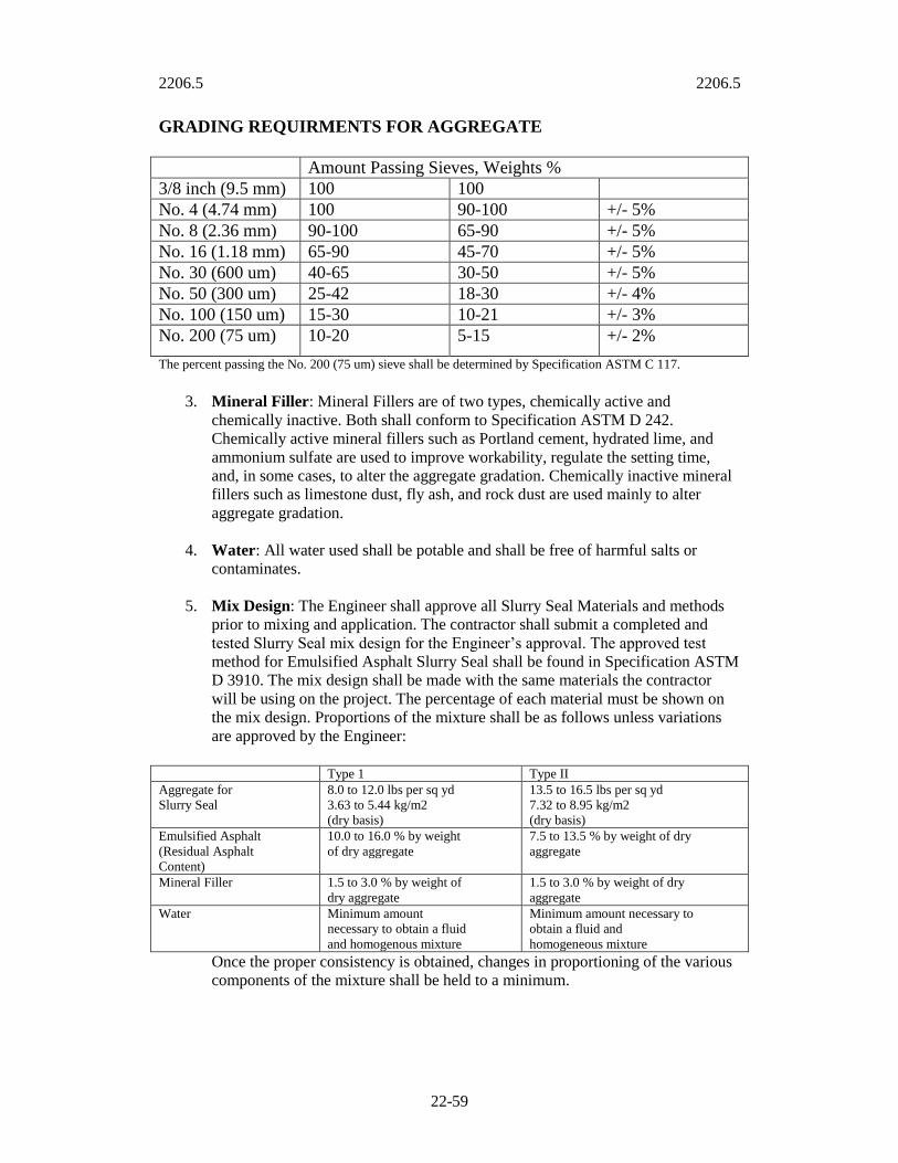
2206.5 2206.5
22-59
GRADING REQUIRMENTS FOR AGGREGATE
Amount Passing Sieves, Weights %
3/8 inch (9.5 mm) 100 100
No. 4 (4.74 mm) 100 90-100 +/- 5%
No. 8 (2.36 mm) 90-100 65-90 +/- 5%
No. 16 (1.18 mm) 65-90 45-70 +/- 5%
No. 30 (600 um) 40-65 30-50 +/- 5%
No. 50 (300 um) 25-42 18-30 +/- 4%
No. 100 (150 um) 15-30 10-21 +/- 3%
No. 200 (75 um) 10-20 5-15 +/- 2%
The percent passing the No. 200 (75 um) sieve shall be determined by Specification ASTM C 117.
3. Mineral Filler: Mineral Fillers are of two types, chemically active and
chemically inactive. Both shall conform to Specification ASTM D 242.
Chemically active mineral fillers such as Portland cement, hydrated lime, and
ammonium sulfate are used to improve workability, regulate the setting time,
and, in some cases, to alter the aggregate gradation. Chemically inactive mineral
fillers such as limestone dust, fly ash, and rock dust are used mainly to alter
aggregate gradation.
4. Water: All water used shall be potable and shall be free of harmful salts or
contaminates.
5. Mix Design: The Engineer shall approve all Slurry Seal Materials and methods
prior to mixing and application. The contractor shall submit a completed and
tested Slurry Seal mix design for the Engineer’s approval. The approved test
method for Emulsified Asphalt Slurry Seal shall be found in Specification ASTM
D 3910. The mix design shall be made with the same materials the contractor
will be using on the project. The percentage of each material must be shown on
the mix design. Proportions of the mixture shall be as follows unless variations
are approved by the Engineer:
Type 1 Type II
Aggregate for
Slurry Seal
8.0 to 12.0 lbs per sq yd
3.63 to 5.44 kg/m2
(dry basis)
13.5 to 16.5 lbs per sq yd
7.32 to 8.95 kg/m2
(dry basis)
Emulsified Asphalt
(Residual Asphalt
Content)
10.0 to 16.0 % by weight
of dry aggregate
7.5 to 13.5 % by weight of dry
aggregate
Mineral Filler 1.5 to 3.0 % by weight of
dry aggregate
1.5 to 3.0 % by weight of dry
aggregate
Water Minimum amount
necessary to obtain a fluid
and homogenous mixture
Minimum amount necessary to
obtain a fluid and
homogeneous mixture
Once the proper consistency is obtained, changes in proportioning of the various
components of the mixture shall be held to a minimum.
2206.5 2206.5
22-60
6. Application Rates: The Slurry Seal mixture shall be of proper consistency at all
times so as to provide the application rate required by the surface condition and
shall be in accordance with the following:
Type I: 8.0 to 12.0 lbs per sq yd (3.63 to 5.44 kgs per sq meter)
Type II: 13.5 to 20 lbs per sq yd (5.44 to 9.07 kgs per sq meter)
Application rates are affected by the unit weight of the aggregate, the gradation
of the aggregate and the demand of the surface to which the slurry seal is being
applied.
7. Equipment: The slurry mixing machine shall be a continuous flow mixing unit
and shall be capable of delivering accurately a predetermined proportion of
aggregate, water and asphalt emulsion to the mixing chamber and to discharge
the thoroughly mixed product on a continuous basis. The equipment shall be
capable of prewetting the aggregate immediately prior to mixing with the
emulsion. The mixing unit of the mixing chamber shall be capable of thoroughly
blending all of the components together without violent mixing. The mixing
machine shall be equipped with an approved fines feeder that includes an
accurate metering device or method to introduce a predetermined proportion of
mineral filler into the mixer. The mineral filler shall be fed at the same time and
location as the aggregate. The fines feeder shall be required whenever added
mineral filler is a part of the aggregate blend. The mixing machine shall be
equipped with a water pressure system and fog-type spray bar, adequate for
complete fogging of the surface receiving slurry treatment. Attached to the mixer
machine shall be a mechanical type squeegee distributor, equipped with flexible
material in contact with the surface of the pavement to prevent loss of slurry from
the distributor. It shall be maintained so as to prevent loss of slurry on varying
grades and crown by adjustments to insure uniform spread. There shall be a
steering device and a flexible strike-off. The spreader box shall have an
adjustable width. The box shall be kept clean and build up of asphalt and
aggregate on the box or in the corners shall not be permitted. Use of burlap drags
or other drags shall be approved by the Engineer. Hand squeegees, shovels, and
other equipment shall be provided if necessary to supplement the slurry mixing
machine. Power brooms, power blowers, air compressors, and hand brooms
suitable for cleaning the surface and cracks of the existing surface shall be
implemented to provide a clean surface.
8. Construction Requirements:
a. Surface Preparation: Immediately prior to applying the slurry, clean the
surface of all loose material, mud spots, vegetation, and other objectionable
material. Any standard cleaning method used to clean pavements will be
acceptable except water flushing. A pickup sweeper must be used unless
otherwise approved by the Engineer. Manholes, valve boxes, drop inlets, and
other service entrances shall be protected from the slurry seal by a method
approved by the Engineer.

2206.5 2206.5
22-61
b. Application: The surface shall be prewetted by fogging ahead of the slurry
box unless waived by the Engineer. Water used in prewetting the surface
shall be applied at such a rate that the entire surface is damp with no apparent
flowing water in front of the slurry box. The slurry mixture shall be of the
desired consistency upon deposit on the surface and no additional elements
shall be added. Total time of mixing shall not exceed 4 minutes. A sufficient
amount of slurry shall be carried in all parts of the spreader at all times so
that a complete coverage is obtained. Overloading of the spreader shall be
avoided. No lumping, balling, or unmixed aggregate shall be permitted. No
segregation of the emulsion and aggregate fines from the coarse aggregate
shall be permitted. If the coarse aggregate settles to the bottom of the mix,
the slurry shall be removed from the pavement. No excessive breaking of
emulsion shall be allowed in the spreader box. No streaks, such as those
caused by oversized aggregate will be left in the finished pavement.
c. Hand Work: Approved squeegees shall be used to spread slurry in areas not
accessible to the slurry mixer. Care should be exercised in leaving no
unsightly appearance from the hand work.
d. Curing: Treated areas shall be allowed to cure for four hours, or until such
time as the Engineer permits their opening to traffic.
e. Weather Limitation: The slurry seal shall not be applied if either the
pavement or air temperature is below 60F (18C) and falling. The mixture
shall not be applied if the relative humidity exceeds 80%.
f. Traffic Control: Suitable methods shall be used to protect the slurry from all
types of traffic until sufficiently cured to accept traffic. The length of time
before traffic is permitted to use the surface depends on the type of
emulsified asphalt, mixture characteristics, and weather conditions.
g. Lines: Care shall be taken to insure straight lines along curb and shoulders.
No runoff on these areas will be permitted. Lines at intersections will be kept
straight to provide good appearance.
h. Property Owners Notification: The Contractor shall supply and place door
tags on the doors of all involved property owners. The door tag shall comply
with the sample language provided by the Engineer.
i. Provisions for Public Convenience During Sealing Operation: The
Contractor shall provide and maintain sufficient signs, barricades, warning
lights, flag persons and watch persons to protect the work and public in a
manner satisfactory to the Engineer. Any areas damaged prior to acceptance
by the City shall be repaired at the Contractor’s expense. “No Parking” signs
will be furnished by the Contractor. These signs shall comply with the
standards established by the MUTCD with regard to size, color, working
height and placement. When “No Parking” signs are posted on the streets
with parking meters, the Contractor shall cover the parking meter heads with
cloth or paper bags. The Contractor shall take all necessary precautions to
protect the public (pedestrian and vehicular) from flying debris. The
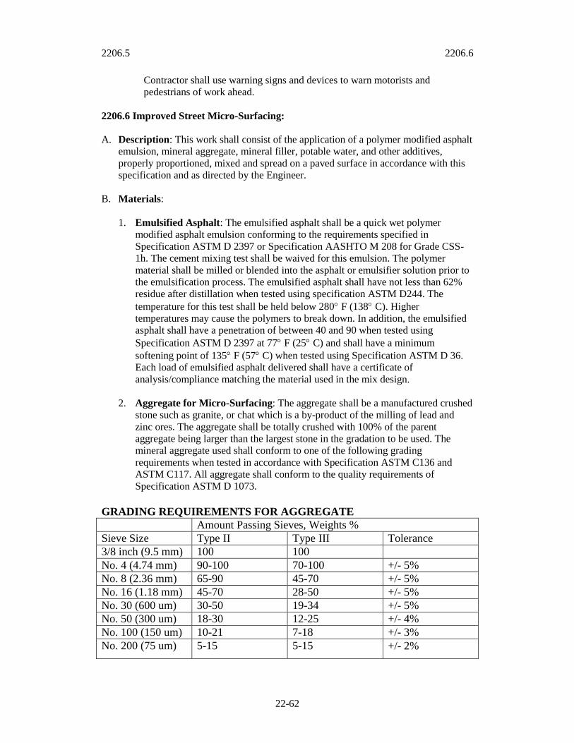
2206.5 2206.6
22-62
Contractor shall use warning signs and devices to warn motorists and
pedestrians of work ahead.
2206.6 Improved Street Micro-Surfacing:
A. Description: This work shall consist of the application of a polymer modified asphalt
emulsion, mineral aggregate, mineral filler, potable water, and other additives,
properly proportioned, mixed and spread on a paved surface in accordance with this
specification and as directed by the Engineer.
B. Materials:
1. Emulsified Asphalt: The emulsified asphalt shall be a quick wet polymer
modified asphalt emulsion conforming to the requirements specified in
Specification ASTM D 2397 or Specification AASHTO M 208 for Grade CSS-
1h. The cement mixing test shall be waived for this emulsion. The polymer
material shall be milled or blended into the asphalt or emulsifier solution prior to
the emulsification process. The emulsified asphalt shall have not less than 62%
residue after distillation when tested using specification ASTM D244. The
temperature for this test shall be held below 280F (138C). Higher
temperatures may cause the polymers to break down. In addition, the emulsified
asphalt shall have a penetration of between 40 and 90 when tested using
Specification ASTM D 2397 at 77F (25C) and shall have a minimum
softening point of 135F (57C) when tested using Specification ASTM D 36.
Each load of emulsified asphalt delivered shall have a certificate of
analysis/compliance matching the material used in the mix design.
2. Aggregate for Micro-Surfacing: The aggregate shall be a manufactured crushed
stone such as granite, or chat which is a by-product of the milling of lead and
zinc ores. The aggregate shall be totally crushed with 100% of the parent
aggregate being larger than the largest stone in the gradation to be used. The
mineral aggregate used shall conform to one of the following grading
requirements when tested in accordance with Specification ASTM C136 and
ASTM C117. All aggregate shall conform to the quality requirements of
Specification ASTM D 1073.
GRADING REQUIREMENTS FOR AGGREGATE
Amount Passing Sieves, Weights %
Sieve Size Type II Type III Tolerance
3/8 inch (9.5 mm) 100 100
No. 4 (4.74 mm) 90-100 70-100 +/- 5%
No. 8 (2.36 mm) 65-90 45-70 +/- 5%
No. 16 (1.18 mm) 45-70 28-50 +/- 5%
No. 30 (600 um) 30-50 19-34 +/- 5%
No. 50 (300 um) 18-30 12-25 +/- 4%
No. 100 (150 um) 10-21 7-18 +/- 3%
No. 200 (75 um) 5-15 5-15 +/- 2%

2206.6 2206.6
22-63
The combined aggregate prior to the addition of any chemically active mineral
filler shall have a sand equivalent of not less than 65 when tested by
Specification ASTM D 2419. The aggregate shall have a weighed average loss
not greater than 25% using magnesium sulfate when tested by Specification
ASTM C 88. Testing of abrasion resistance shall not exceed 30% when tested by
Specification ASTM C 131.
3. Mineral Filler: Mineral filler shall be any recognized brand of non-irentrained
Portland cement or hydrated lime. The mineral filler shall be free of lumps and
accepted upon visual inspections. The type and amount of mineral filler needed
shall be determined by a laboratory mix design and will be considered as part of
the aggregate gradation. .
4. Water: All water used shall be potable and shall be free of harmful salts or
contaminates.
5. Additives: Additives may be added to the emulsion mix or any of the component
materials to provide the control of the quick-traffic properties. They must be
included as part of the mix design and be compatible with the other components
of the mix.
6. Mix Design: The Engineer shall approve all Micro-Surfacing Materials and
methods prior to mixing and application. The contractor shall submit a completed
and tested Micro-Surfacing mix design for the Engineer’s approval. The
approved test method for Micro-Surfacing shall be found in Specification ASTM
D 6372. The mix design shall be made with the same materials the contractor
will be using on the project. The percentage of each material must be shown on
the mix design. Proportions of the mixture shall be as follows unless variations
are approved by the engineer.
Type 1I Type III
Aggregate for
Micro-Surfacing
10.0 to 20.0 lbs per sq yd
4.53 to 9.07 kg/m2
(dry basis)
15.0 to 30.0 lbs per sq yd
6.80 to 13.61 kg/m2
(dry basis)
Emulsified Asphalt
(Residual Asphalt
Content)
7.5 to 13.5 % by weight of
dry aggregate
5.5 to 13.5 % by weight
of dry aggregate
Polymer Based
Modifier
Minimum of 3% solids
based on asphalt weight
content
Minimum of 3% solids
Based on asphalt weight
content
Additive As needed As needed
Mineral Filler 0.0 to 3.0 % by weight of
dry aggregate
0.0 to 3.0 % by weight of
dry aggregate
Water Minimum amount necessary
to obtain a fluid and
homogenous mixture
Minimum amount
necessary to obtain a fluid
and homogeneous
mixture
Once the proper consistency is obtained, changes in proportioning of the various
components of the mixture shall be held to a minimum.
7. Application Rates: The Micro-Surfacing mixture shall be of proper consistency
at all times so as to provide the application rate required by the surface condition
and shall be in accordance with the following:
2206.6 2206.6
22-64
Type II: 10.0 to 20.0 lbs per sq yd (5.4 to 18.6 kgs per sq meter)
Type III: 15.0 to 30.0 lbs per sq yd (8.1 to 16.2 kgs per sq meter)
Application rates are affected by the unit weight of the aggregate, the gradation
of the aggregate, and the demand of the surface to which the micro-surfacing is
being applied.
8. Equipment:
a. Micro-Surfacing Mixing Equipment: The Micro-Surfacing mixing
machine shall be specifically designed and manufactured to lay
microsurfacing. The machine shall be self propelled, continuous flow mixing
unit able to accurately deliver and proportion the aggregate, emulsified
asphalt, mineral filler, control setting additive, and water to a revolving
multi-blade double shafted mixer and discharge the mixed product on a
continuous flow basis. The machine shall have sufficient storage capacity for
aggregate, emulsified asphalt, mineral filler, control additive, and water to
maintain an adequate supply to the proportioning controls. On major
highway work, the machine may be required to be a self loading machine
capable of loading materials while continuing to lay microsurfacing. The self
loading machine shall be equipped to allow the operator to have full control
of the forward and reverse speed during application of the micro-surfacing
material and be equipped with opposite side drivers stationed to assist in
alignment. The self loading device, opposite side drivers stations, and
forward and reverse speed controls shall be original equipment manufacturer
designed.
b. Proportioning Devices: Individual volume or weight controls for
proportioning each material, and used in material calibration, shall be
provided and properly marked.
c. Calibration: Each mixing unit to be used in the performance of the work
shall be calibrated prior to construction. Calibration documentation shall
include an individual calibration of each material at various settings, which
can be related to the machine metering devices. No machine will be allowed
to work on the project until a calibration has been completed. Final
calibration sheets shall be provided to the Engineer for acceptance.
d. Micro-Surfacing Spreading Equipment: The machine shall include a
surfacing box with twin shafted paddles or spiral augers fixed in a spreader
box. A flexible front seal shall be provided to insure no loss of mixture at the
road surface contact point. The rear flexible seal shall act as a final strike-off
and shall be adjustable in width. The spreader box and rear strike-off shall be
so designed and operated that a uniform consistency is achieved to produce a
free flow of material to the rear strike-off box. The box shall have suitable
means provided to side-shift the box to compensate for variations of
pavement geometry. A secondary strike-off shall be provided to improve the
surface texture. It shall have the same leveling adjustments as the spreader
box.
2206.6 2206.6
22-65
e. Auxiliary Equipment: Hand squeegees, shovels, traffic control equipment,
and other support and safety equipment shall be provided if necessary to
perform the work.
f. Cleaning Equipment: Power brooms, pickup sweepers, power blowers, air
compressors, and hand brooms suitable for cleaning shall be utilized to
provide a clean surface.
9. Construction Requirements:
a. Surface Preparation: Immediately prior to applying the microsurfacing, the
surface shall be cleaned of all loose material, silt spots, vegetation, and
objectionable material as determined by the Engineer. Any standard cleaning
method used to clean pavements will be acceptable except water flushing.
Manholes, valve boxes, drop inlets, and other service entrances shall be
protected from the micro-surfacing by a method approved by the Engineer.
b. Application: If the pavement area to be covered is extremely oxidized and
raveled or is concrete or brick, a tack coat may be required at the discretion
of the Engineer. The tack coat shall conform to Section 2204 and shall be a
SS or CSS grade. The tack coat shall be allowed to cure sufficiently before
the application of micro-surfacing. The surface shall be prewetted by fogging
ahead of the spreader box unless waived by the Engineer. Water used in
prewetting the surface shall be applied at such a rate that the entire surface is
damp with no apparent flowing water in front of the spreader box. The
micro-surfacing mixture shall be of the desired consistency upon deposit on
the surface and no additional elements shall be added. A sufficient amount of
material shall be carried in all parts of the spreader box at all times so that a
complete coverage is obtained. Overloading of the spreader box shall be
avoided. No lumping, balling, or unmixed aggregate shall be permitted. No
streaks, such as those caused by oversized aggregate shall be left in the
finished surface.
c. Hand Work: Areas which cannot be reached with the mixing machine shall
be surfaced using approved hand squeegees to provide a complete and
uniform coverage. If necessary, the area to be hand worked shall be lightly
dampened prior to mix placement. The same type of finish as applied by the
spreader box shall be required.
d. Curing: Micro surfacing shall be allowed to cure for one hour, or until the
Engineer permits opening the street to traffic.
e. Weather Limitation: Micro-surfacing shall not be applied if either the
pavement or air temperature is below 60F (18C) and falling. The mixture
shall not be applied if the relative humidity exceeds 80%.
f. Traffic Control: Suitable methods shall be used to protect the
microsurfacing from all types of traffic until sufficiently cured to accept
traffic. The length of time before traffic is permitted to use the surface shall
be determined by the Engineer.

2206.6 2206.8
22-66
g. Lines: Care shall be taken to insure straight lines along curb and shoulders.
No runoff on these areas will be permitted. Lines at intersections will be kept
straight to provide good appearance.
h. Property Owners Notification: The Contractor shall supply and place door
tags on the doors of all involved property owners. The door tag shall comply
with the sample language provided by the Engineer.
i. Provisions for Public Convenience During Surfacing Operation: The
Contractor shall provide and maintain sufficient signs, barricades, warning
lights, flag persons and watch persons to protect the work and public in a
manner satisfactory to the Engineer. Any areas damaged prior to acceptance
by the City shall be repaired at the Contractor’s expense. “No Parking” signs
will be furnished by the Contractor. These signs shall comply with the
standards established by the MUTCD with regard to size, color, working
height and placement. When “No Parking” signs are posted on the streets
with parking meters, the Contractor shall cover the parking meter heads with
cloth or paper bags. The Contractor shall take all necessary precautions to
protect the public (pedestrian and vehicular) from flying debris. The
Contractor shall use warning signs and devices to warn motorists and
pedestrians of work ahead.
2206.7 Method of Measurement:
A. Asphaltic Crack Seal will be measured per pound (kilogram).
B. Chip seal will be measured by one of the following:
1. Per square yard (square meter) or tenth part thereof.
2. Actual quantities used:
a. Asphaltic concrete patch, per ton (metric ton) or tenth part thereof.
b. Bitumen (asphaltic cement or liquid asphalt) per gallon (liter).
c. Coated cover aggregate, per ton (metric ton) or tenth part thereof.
C. Slurry seal will be measured per square yard (square meter) or tenth part thereof.
D. Microsurfacing will be measured per square yard (square meter) or tenth part thereof.
2206.8 Basis of Payment:
A. Asphaltic Crack Seal will be paid for by one of the following:
1. Contract unit bid price.
2. Contract lump sum bid price.

2206.8 2206.8
22-67
B. Chip Seal will be paid for by one of the following:
1. Contract unit bid price.
2. Contract lump sum bid price.
C. Slurry Seal will be paid for by one of the following:
1. Contract unit bid price.
2. Contract lump sum bid price.
D. Microsurfacing will be paid for by one of the following:
1. Contract unit bid price.
2. Contract lump sum bid price.
2207 2207.3
22-68
SECTION 2207 COLD MILLING
2207.1 Summary: This section includes cold milling pavement surfaces.
2207.2 Equipment: Milling the surface of pavements shall be completed by the use of a
milling machine conforming to the following:
A. Machine: The cold milling machine shall be self-propelled and shall have in
combination the means of milling and cutting, without softening the old surface and
blading the cuttings into a single windrow, or depositing them directly into a truck.
B. Air Pollution: The machine shall be equipped with a dust suppression system
including water storage tanks and high pressure spray bars.
C. Operating Width: It is desirable that the cutting width be greater than 6 feet (2 m).
In the event the cutting width is less than 6 feet (2 m) a system of electronic grade
control for consecutive passes will be required.
D. Cutting Drum: The cutting drum shall be totally enclosed to prevent discharge of
any loosened material on adjacent work areas.
E. Warning Light: The milling machine shall be equipped with a flashing warning light
visible from 360 degrees. The light shall be mounted near the rear of the machine, at
least 2 feet (61 cm) above the highest part of the milling machine, and shall be used
whenever the machine is being used or moved upon the City streets.
2207.3 Construction Details:
A. Methods of Operations for Milling:
1. Operator: The milling machine shall be operated by an experienced and capable
operator.
2. Utilities: Street surfaces adjacent to manholes, water valves and other utility
extensions shall be completely removed to the full depth of cut specified for the
street unless otherwise specified by the Engineer.
3. Material Disposal: All material from the milling operation shall immediately
be removed from the surface of the pavement and properly disposed of by the
contractor at an approved disposal area.
4. Surface Conditions: The drum lacing patterns shall produce a smooth surface
finish after milling, with groove depths not to exceed 1/4 inch (0.64 cm) and
groove spacing not to exceed 1 inch (2.54 cm) unless otherwise approved by the
Engineer.
B. Types of Cuts to be made by Milling:
1. Leveling: Sufficient passes shall be made such that all irregularities or high spots
are eliminated, and that 100% of the surface is milled.

2207.3 2207.5
22-69
2. Average Depth: Sufficient passes, or cuts, shall be made in order to remove a
specified depth over the entire street section. These depths will be designated in
the Special Provisions.
3. Curb Cut: Sufficient passes or cuts shall be made in order to remove a specified
depth at the curb for a specified width. The depth at the width furthest from the
curb is 0. These dimensions will be designated in the Special Provisions.
4. Bridge Deck Milling: Sufficient passes, or cuts, shall be made in order to
remove the material as specified on-the plans or in the Special Provisions.
C. Cleanup: All loose asphalt and debris shall be removed from the street surface and
curb and gutter. Any material and debris that adheres to the curb and gutter shall be
removed.
2207.4 Method of measurement: Cold milling will be measured per square yard (square
meter) or tenth part thereof for the specified depth.
2207.5 Basis of payment: Cold milling will be paid for by one of the following:
A. Contract unit bid price.
B. Contract lump sum bid price.
2208 2208.1
22-70
SECTION 2208 PORTLAND CEMENT CONCRETE PAVEMENT
Referenced Standards: The following standards are referenced directly in this section.
The latest version of these standards shall be used.
ASTM
A 185 Standard Specification for Steel Welded Wire Fabric, Plain, for Concrete
Reinforcement
A 615 Standard Specification for Deformed and Plain Billet-Steel Bars for Concrete
Reinforcement
C 1116 Standard Specification for Fiber-Reinforced Concrete and Shotcrete C 1315
Specification for Liquid Membrane-Forming Compounds Having Special
Properties for Curing and Sealing Concrete
C 1399 Test Method for Obtaining Average Residual-Strength of Fiber-Reinforced
Concrete
D 1751 Standard Specification for Preformed Expansion Joint Filler for Concrete Paving
and Structural Construction (Nonextruding and Resilient Bituminous Types)
D 1752 Standard Specification for Preformed Sponge Rubber and Cork Expansion Joint
Fillers for Concrete Paving and Structural Construction
D 2628 Standard Specification for Preformed Polychloroprene Elastomeric Joint Seals
for Concrete Pavements
D 2835 Standard Specification for Lubricant for Installation of Preformed Compression
Seals in Concrete Pavements
D 6690 Standard Specification for Joint and Crack Sealants, Hot-Applied, for
Concrete and Asphalt Pavements
D 3406 Standard Specification for Joint Sealant, Hot-Applied, Elastomeric-Type, for
Portland Cement Concrete Pavements
E 965 Test Method for Measuring Surface Macrotexture Depth Using a Sand
Volumetric Technique
AASHTO
M 213 Preformed Expansion Joint Fillers for Concrete Paving and Structural
Construction (Nonextruding and Resilient Bituminous Types)
M 220 Preformed Polychloroprene Elastomeric Joint Seals for Concrete Pavements
M 282 Joint Sealants, Hot-Poured, Elastomeric Type, for Portland Cement Concrete
Pavements
M 324 Joint Sealants, Hot-Poured, for Concrete and Asphalt Pavements
MCIB
Section 1 Concrete Materials
2208.0 General: The term expansion join, when used in plans, standard drawings or
other specifications shall be understood to mean isolation joint.
2208.1 Summary: This section includes the construction of Portland Cement Concrete
pavement. All materials and placement shall be tested as outlined in the “Public Works
Department Materials Testing Requirements”.
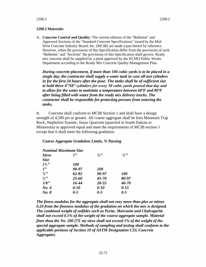
2208.2 2208.2
22-71
2208.2 Materials:
A. Concrete Control and Quality: The current editions of the "Bulletins" and
Approved Sections of the "Standard Concrete Specifications" issued by the Mid-
West Concrete Industry Board, Inc. (MCIB) are made a part hereof by reference.
However, when the provisions of this Specification differ from the provisions of such
"Bulletins" and "Sections" the provisions of this Specification shall govern. Ready
mix concrete shall be supplied by a plant approved by the KCMO Public Works
Department according to the Ready Mix Concrete Quality Management Plan.
During concrete placement, if more than 100 cubic yards is to be placed in a
single day, the contractor shall supply a water tank to cure all test cylinders
in for the first 24 hours after the pour. The tanks shall be of sufficient size
to hold three 4”X8” cylinders for every 50 cubic yards poured that day and
to allow for the water to maintain a temperature between 60ºF and 80ºF
after being filled with water from the ready mix delivery trucks. The
contractor shall be responsible for protecting persons from entering the
tanks.
B. Concrete shall conform to MCIB Section 1 and shall have a design
strength of 4,500 psi or greater. All coarse aggregate shall be Iron Mountain Trap
Rock, Nepheline Syenite, Sioux Quartzite (quarried in South Dakota or
Minnesota) or approved equal and meet the requirements of MCIB section 1
except that it shall meet the following gradation:
Coarse Aggregate Gradation Limits, % Passing
Nominal Maximum Size
Sieve 1” ¾” ½”
Size
1½” 100
1” 90-97 100
¾” 62-82 90-97 100
½” 25-60 45-70 80-97
3/8” 16-44 20-55 40-70
No. 4 0-10 0-10 0-15
No. 8 0-5 0-5 0-5
The finess modulus for the aggregate shall not vary more than plus or minus
0.20 from the fineness modulus of the gradation on which the mix is designed.
The combined weight of sulfides such as Pyrite, Marcasite and Chalcopyrite
shall not exceed 0.1% of the weight of the course aggregate sample. Material
finer than the No. 200 (75m) sieve shall not exceed 1% of the weight of the
special aggregate sample. Methods of sampling and testing shall conform to the
applicable portions of Section 10 of ASTM Designation C33, Concrete
Aggregates.
2208.2 2208.2
22-72
ASR potential of the mix shall be mitigated as necessary. Fly Ash shall conform
to ASTM C 618. Slag shall conform to ASTM C989, Strength Grade 120.
Concrete for ultra-thin whitetopping (UTW) projects shall also include fiber
reinforcement conforming to 2208.2.C.4 and shall have a maximum
nominal coarse aggregate size of 1/3 the thickness of the concrete overlay.
If supplemental cementitious materials are to be substituted for cement in
the production of concrete, the effect on the setting time must be taken into
consideration and the concrete shall be protected from the weather until it
reaches 50% of its design strength.
C. A mix design, for all concrete mixes to be used, shall be submitted to the
City for review a minimum of 14 days before use and be approved prior to
placement. As a minimum the following information must be in the QM file
for the plant or included with the mix design:
Mix design designation required by project
Project name, location, project number and date
Name and location of ready mix plant or plants
List the source and type of all materials from each plant supplying
mix
CA and FA Sieve Analysis and quality checks from each plant
supplying mix. CA-Ledge, quarry or mine name and location. FA-
Sand plant name, location and source (MO or Kaw River) (less than
6 months old)
ASR test results (less than 2 years old)
Durability Factor test results for CA (less than 2 years old)
Cement chemical analysis
Specific gravity of all materials
The mix design shall be based on one cubic yard of concrete or one
cubic meter if required
The mix design shall contain the weight and volume of each mix
component (S.S.D.)
The results of 7-day and 28-day compressive strengths shall be
submitted when required
On bridge deck pours the concrete shall be supplied from only one
plant
C. Reinforcement:
1. Bars: Bars shall be epoxy coated and conform to ASTM A 775.
2. Welded Steel Wire: Welded steel wire fabric shall conform to ASTM A 185.

2208.2 2208.2
22-73
3. Supporting Elements: Representative samples of supporting elements shall be
submitted and approved by the Engineer prior to their use in the project.
4. Fibers: Where required, fibers shall be applied at the rate of 3 pounds per cubic
yard (1.8 kg per cubic meter) of concrete. Fibers for concrete reinforcement shall
be composed of only 100% virgin homopolymer polypropylene, fibrillated and
graded. Fibers shall contain no reprocessed olefin materials, and shall be
specifically manufactured to an optimum gradation for use as secondary concrete
reinforcement, meeting the requirements of ASTM C 1116, Type III, 4.1.3, and
ASTM C 1116 Performance Level 1, and a minimum residual strength of 30 psi
(210 kPa) per ASTM C 1399, average of 4 beams sampled at the point of
discharge (or when appropriate, the point of placement.
D. Isolation Joint Fillers: Isolation joint fillers shall conform to ASTM D 1752 or
D7174.
E. Joint Sealing Compounds: Joint sealing compounds shall conform to the standards
for the type of sealant specified as listed in the following table:
Joint Seals and Sealants AASHTO ASTM
Hot-poured, Polymeric Asphalt Based M 324 D 6690
Hot-poured, Elastomeric - Type M 282 D 3406
Preformed Polychloroprene Elastomeric M 220 D 2628
Lubricant for Installation of Preformed Seal -- D 2835
Preformed Expansion Joint Filler M 213 D 1751
F. Curing Membrane: All material to be used or employed in curing Portland Cement
Concrete must be approved by the Engineer prior to its use. It shall be of the liquid
membrane type and shall conform to ASTM C 1315, Type II, Class A.
2208.3 Construction Details: Portland Cement Concrete pavement shall be constructed
to the configuration, and to the lines and grades shown on the plans.
A. Grading and Subgrade Preparation: All excavation or embankment required shall
be as defined in sections 2100 and 2201 entitled "Grading," and "Subgrade
Preparation. "If areas of the subgrade are below the lines and grades shown on the
plans, they shall be brought to the proper line and grade by one of the following:
1. Additional fill material placed in accordance with Sections 2100 and 2201.
2. Areas may be filled with Untreated Compacted Aggregate conforming to Section
2202.
3. Areas may be filled with additional thickness of Portland Cement Concrete
Pavement.
B. Asphalt Surface Preparation for Ultra-thin Whitetopping:

2208.2 2208.2
22-74
1. Mill existing asphalt surface to the depth indicated on the project drawings.
When measured with a straightedge or stringline, the surface should be true to the
plan drawings. The milled surface shall be no more than ½ inch (12.5 mm) below
or ¼ inch (6 mm) above the plan grade.
2. Remove all loose foreign material from the asphalt surface with compressed air,
by brooming, or by other methods immediately prior to the placing of concrete.
A pickup sweeper must be used unless otherwise directed by the Engineer.
3. The asphalt surface shall not be below 40F (4C), and shall be free of any
standing water prior to the placement of concrete.
4. Water shall be used to cool the asphalt surface when the surface temperature is
above 100F (37.8C), but shall be free of any standing water prior to the
placement of the concrete.
C. Concrete Surface Preparation for Portland Cement Concrete Bonded Overlay:

2208.3 2208.4
22-75
1. Remove the entire surface of the existing concrete pavement (.25 in. / 5 mm
nominal) by milling.
2. Clean the existing concrete pavement by shot blasting.
3. Thoroughly wet the concrete surfaces to which the overlay is to bond with clean
water for not less than two hours before the placing of the concrete. Blow away
all free water immediately ahead of the placing operation. Bonding surfaces
should be maintained in a damp condition with no free standing water.
D. Forms: All forms shall be in good condition, clean, and free from imperfections.
Each form shall not vary more than 1/4 inch (0.64 cm) in horizontal and vertical
alignment for each 10 feet (3.05 m) of length.
1. Material & Size: Forms shall be made of metal and shall have a height equal to
or greater than the prescribed edge thickness of the pavement slab.
2. Strength: Forms shall be of such cross-section and strength, and so secured as to
resist the pressure of the concrete when struck off, vibrated, and finished, and the
impact and vibration of any equipment which they may support.
3. Installation: Forms shall be set true to line and grade, supported through their
length and, joined neatly in such a manner that the joints are free from movement
in any direction.
4. Preparation: Forms shall be cleaned and lubricated prior to each use and shall
be so designed to permit their removal without damage to the new concrete.
2208.4 Joints: Generally joints shall be formed at right angles to the true alignment of
the pavement and to the depths and configuration specified by the appropriate standard or
as modified by the plans and specifications.
A. Isolation joints: Isolation joints shall be placed at all locations where shown on the
plans and standards or as directed by the Engineer.
1. Isolation joints shall extend the entire width of the pavement and from the
subgrade to one inch (25 mm) below the surface of the pavement or the material
will have a suitable tear strip provided to allow for the application of the joint
sealer.
2. Under no circumstances shall any concrete be left across the isolation joint at any
point.
3. Material: Isolation joints shall be formed by a one piece, one inch (2.54 cm)
thick preformed joint filler cut to the configuration of the correct pavement
section.
4. Stability: Isolation joints shall be secured in such a manner that they will not be
disturbed during the placement, consolidation and finishing of the concrete.

2208.4 2208.4
22-76
5. Dowels: If isolation joints are to be equipped with dowels they shall be of the
size and type specified, and shall be firmly supported in place, by means of a
dowel basket which shall remain in place. One half of each dowel shall be lightly
painted or greased with a product approved by the engineer.
B. Contraction joints: Contraction joints shall be placed where indicated and to the
depth indicated by the plans, specifications and standards.
1. Method: Contraction joints shall be sawed.
2. When sawing joints, the contractor shall begin as soon as the concrete hardens
sufficiently to prevent excessive raveling along the saw cut and shall finish
before conditions induce uncontrolled cracks, regardless of the time or weather.
The longitudinal contraction joints shall be sawed immediately after sawing
transverse joints. When joint sealing backup material is specified with sawed
joints, the first stage, which provides a relief cut shall be approximately 1/8 inch
(3 mm) wide, and shall be to plan depth. The second stage which widens the
joints to allow the insertion of joint sealing backup material to plan depth shall
not be performed until the concrete is at least 48 hours old, and shall be delayed
longer when the sawing causes raveling of the concrete. If second stage sawing is
performed prior to the completion of the curing period, the contractor shall
maintain the cure by use of curing tapes, plastic devices, or other materials
approved by the engineer.
3. For Portland cement concrete pavements, contraction joints shall be one-forth
(1/4) the thickness of the slab (minimum).
4. Where not indicated on the plan drawings, joint spacing for ultra-thin
whitetopping projects shall not exceed 12 times the thickness of the overlay, and
shall be constructed such that the larger dimension of any panel does not exceed
125% of the smaller dimension. Joints of adjacent panels shall be aligned. Joints
shall intersect pavement free edges at 90 degrees, and shall extend a minimum of
1 ft (300 mm) from the pavement edge. Saw joints shall be one-third the
thickness of the slab, or two inches (50 mm), whichever is greater.
5. For bonded Portland cement concrete overlays, joints shall be located above
existing joints, shall be sawed full depth plus one-half inch (12mm) for overlays
up to 4 inches (100 mm) in two stages. The first stage provides a relief cut
approximately 1/8 inch (3 mm) wide.
6. Dowels: If contraction joints are to be equipped with dowels they shall be of the
size and type specified and shall be firmly supported in place and accurately
aligned parallel to the pavement line and grade with an allowable tolerance of 1/8
inch (3 mm).
C. Longitudinal and Construction joints: Longitudinal joints or construction joints
shall be placed as shown on the plans or where the Contractor's construction
procedure may require them to be placed. Longitudinal construction joints (joints
between construction lanes) shall be keyed or tied joints of the dimensions shown on
the plans or standards.

2208.4 2208.5
22-77
D. Center joints: Longitudinal center joints shall be constructed using the methods
specified in Section 2208.4 B "Contraction joints."
E. Transverse Construction joints: Transverse construction joints of the type shown
on the plans or standards shall be placed wherever concrete placement is suspended
for more than 30 minutes.
F. Tiebars: Tiebars shall be of deformed steel of the dimensions specified by the plans
or standards. Tiebars shall be installed at the specified spacing and firmly secured so
as not to be disturbed by the construction procedure.
2208.5 Placing, Finishing, Curing, and Protection: Concrete shall be furnished in
quantities required for immediate use and shall be placed in accordance with the
requirements of MCIB Concrete Pavement (Section 1). Prior to commencing
construction, the contractor shall furnish a concrete delivery plan which includes at a
minimum the number of trucks which will be dedicated to the project, the location of the
concrete plant, the route and distance from the plant to the job site, and the anticipated
rate of concrete usage. It is essential that concrete be delivered in sufficient quantities to
prevent stoppage of the paving operation.
A. Concrete Placement: The concrete shall be deposited on the subgrade to the
required depth and width of the construction lane in successive batches and in a
continuous operation without the use of intermediate forms or bulkheads. The
subgrade shall be moistened prior to the placement of concrete. The concrete shall be
placed as uniformly as possible in order to minimize the amount of additional
spreading necessary. While being placed, the concrete shall be vibrated and
compacted with suitable tools so that the formation of voids or honeycomb pockets is
prevented.
The concrete shall be well vibrated and tamped against the forms and along all joints.
Care shall be taken in the distribution of the concrete to deposit a sufficient volume
along the outside form lines so that the curb section can be consolidated and finished
simultaneously with the slab.
No concrete shall be placed around manholes or other structures until they have been
brought to the required grade, alignment, and cross slope.
Concrete shall not be allowed to extrude below the forms.
B. Concrete Finishing Methods: The pavement shall be struck off and consolidated
with a mechanical finishing machine. Hand-finishing methods may be used for small
or irregular areas. Furnish paving and finishing equipment applicable to the type of
construction as follows:
1. Slip-form Machines: Furnish slip-form machines capable of spreading,
consolidating, screeding, and float finishing the freshly placed concrete in one
pass to provide a dense and homogeneous pavement with minimal hand
finishing.
2208.5 2208.5
22-78
2. Self-Propelled Form-Riding Machines: Furnish mechanical, self-propelled
spreading and finishing machines capable of consolidation and finishing the
concrete with minimal hand finishing. Do not use machines that displace the
fixed side forms.
3. Manual Fixed-Form Paving Machines: Furnish spreading and finishing
machines capable of consolidating and finishing the concrete with minimal hand
finishing.
4. Hand Methods: When finishing by hand methods, concrete shall be
consolidated by use of vibrating units operating in the concrete. Unless the
vibrating apparatus is such that the full width of concrete is consolidated in a
single passage, a definite system or pattern shall be used in the operation of the
vibrator so the full width of concrete in each linear foot of lane will receive
adequate and uniform consolidation. The system and methods of vibrating shall
be subject to approval of the Engineer. Vibrating equipment shall, under no
circumstances, be used as a tool for moving concrete laterally on the grade.
C. Concrete Finishing:
1. Longitudinal Floating: After the concrete has been struck off and
consolidated, it shall be further smoothed by means of a mechanical
longitudinal float or by float finishers using a longitudinal hand float. If
a longitudinal hand float is used, it.shall be operated from foot bridges
spanning the pavement, and shall be worked with a wiping motion
parallel to the centerline, and passing from one side of the pavement to
the other. Movement ahead along the centerline of the pavement shall be
in successive advances of not more than ½ of the length of the float. The
float shall not be less than 3 feet (91.44cm) in length and 6 inches (15.24
cm) in width, and shall be properly stiffened and provided with handles
at each end. The operation may be eliminated if specified tolerances can
be attained by some other approved method.
In cases where the longitudinal floating operation has been eliminated,
the pavement shall be scraped with a straight edge 10 feet (3.05m) long,
equipped with a handle to permit it to be operated from the edge of the
pavement. The longitudinal float and straightedge shall be operated so
that any excess water and laitance are removed from the surface of the
pavement. After the scraping operation, the surface of the pavement
shall be within the specified tolerances.
2. Straightedging: While the concrete is still plastic, the slab surface shall
be tested for smoothness with a 10-foot (3.05m) straightedge swung from
handles 3 feet (91.44cm) longer than one-half the width of the slab.
Straightedging shall be done on the pavement surface parallel to the
centerline and at not more than 5 foot (1.52m) intervals transversely.
After each test the straightedge shall be moved forward one-half its

2208.5 2208.5
22-79
length and the operation repeated. When irregularities are discovered,
they shall be corrected by adding or removing concrete. All disturbed
places shall be smoothed with a float not less than 3 feet (91.44 cm) long
and not less than 6 inches (15.24 cm) wide, and again straightedged.
The pavement surface shall have no depression in which water will
stand.
3. Edging: Before final finishing is completed and before the concrete has
taken its initial set, the edges of the slab and curb shall be finished to the
radius shown on the plans or standards by the paving equipment, or with
hand edging tools.
4. Final Surface Finish:
a. Dragged Surface Treatment:
1) For roadways with a design speed of 45 MPH (70 KM/H) or less
to be posted 45 MPH (70 KM/H) or less, astroturf or burlap shall
be dragged longitudinally over the finished surface to produce a
tight, uniform textured surface and the edges shall be rounded in
a workmanlike manner.
2) For roadways to be posted 50 MPH (80 KM/H) or more astroturf
or burlap shall be dragged longitudinally over the finished
surface to produce a tight, uniform, textured surface and the
edges shall be rounded in a workmanlike manner. The texture
achieved by the astroturf or burlap drag shall be tested by the
contractor in accordance with ASTM E 965, “Test Method for
Measuring Surface Macrotexture Depth Using a Sand
Volumetric Technique”, to ensure the texture is adequate for
skid resistance. Test locations will be determined by the engineer.
The results of ASTM E 965 shall show an average texture depth
of any lot, as defined below and shall have a minimum value of
0.032 inch (0.80 mm). Any lot showing an average of less than
0.032 inch (0.80 mm) but equal to or greater than 0.024 inch
(0.60 mm) will be accepted as substantial compliance but the
contractor shall amend their operation to achieve the required
0.032 inch (0.80 mm) minimum depth. (It is not the intention of
this tolerance to allow the contractor to continuously pave with
an average texture depth of less than 0.032 inch [0.80mm]). Any
lot showing an average texture depth of less than 0.024 inch
(0.60 mm) shall require diamond grinding of the pavement
represented by this lot to attain the necessary texture. Any
individual test showing a texture depth of less than 0.020 inch
(0.50 mm) shall require diamond grinding of the pavement
represented by this lot to attain the necessary texture. Limits of
2208.5 2208.5
22-80
any failing individual test shall be determined by running
additional tests at 100 foot (30 m) intervals before and after the
failing test location. All testing of the surface texture shall be
completed no later than the day following pavement placement.
b. Groove Treatment: Unless otherwise specified the texture surface of
travel lanes of pavement shall be given a suitable transverse or
longitudinal grooving, or a dragged surface treatment as described
in paragraph 2208.5.C.4.a.2. for roadways to be posted at 50 MPH
(80 KM/H) or more. If grooving is required, surface grooving shall
be done with a mechanical device such as a wire broom or comb or
by hand. The broom or comb shall have a single row of spring steel
tines, rectangular in cross section, 1/8 inch to 3/16 inch (3 mm to 4.8
mm) wide; spaced on ¾ inch (19 mm) centers of sufficient length,
thickness, and resilience to form grooves to a depth of a minimum of
1/8 inch (3 mm) to a maximum of approximately 3/16 (4.8 mm) inch
in the plastic concrete. If grooves are to be hand installed, the
equipment to be used shall be reviewed and approved by the
engineer. This operation shall be done at such time and in such
manner that the desired surface texture will be achieved while
minimizing displacement of the larger aggregate particles and before
the surface permanently sets. Where abutting pavement is to be
placed, the grooving should extend as close to the edge as possible
without damaging the edge. If abutting pavement is not to be placed,
the 6 inch (150 mm) area nearest the edge or 1 foot (300 mm) from
the face of the curb is not required to be grooved. For small or
irregular areas or during equipment breakdown, grooving may be
done by hand methods.
5. Curing: As soon as practical after the concrete is finished, it shall be
cured with an approve curing method. If a liquid curing membrane is
used, it shall be applied in accordance with the manufacturer’s
directions.
a. Methods of Applying Curing Membrane: A nozzle producing a
uniform fan pattern will be used on all spray equipment when
applying the liquid curing membrane. The curing compound should
be applied immediately after final finishing, and before the loss of all
free water on the surface of the concrete. Normally, one smooth even
coat shall be applied at a rate of 150 to 200 square feet per gallon
(3.7 to 3.8 square meters per liter), but two coats may be necessary to
ensure complete coverage and effective protection. Second coat
should be applied at right angles to the first coat.
b. Curing Formed Surfaces: If the forms are removed from finished
concrete pavement within a period of 72 hours or if a slip form
2208.5 2208.5
22-81
paving machine has been used, these surfaces shall also be cured.
Curing membrane damaged by joint sawing operations shall be
repaired by the contractor as directed by the engineer.
6. Protection: The contractor shall, at his own expense, protect the
concrete work against damage or defacement of any kind until it has
been accepted by the engineer. All vehicular traffic shall be prohibited
from using new concrete pavement until it has attained a minimum of
70% of the 28 day design strength. Concrete pavement that is not
acceptable to the engineer because of damage or defacement, shall be
removed and replaced, or repaired to the satisfaction of the engineer, at
the expense of the contractor.
7. Diamond Grinding: If required by the contract, or if pavement
smoothness criteria are not achieved, the contractor shall grind the
riding surface to reduce or eliminate the irregularities.
a. A self-propelled grinding machine with diamond blades mounted on
a multi-blade arbor shall be used. Equipment that causes excessive
ravels, aggregate fractures, or spalls will not be acceptable. A
uniform texture of the full lane width is required.
b. Transverse grooving will not be required.
c. Vacuum equipment or other continuous methods to remove grinding
slurry and residue shall be used. Grinding slurry shall not flow
across lanes being used by traffic.
d. After corrections have been made to the riding surface, the pavement
shall be tested for smoothness using the same technique used to
determine smoothness originally. The contractor shall furnish and
operate the smoothness measurement equipment, and evaluate the
results as specified in Section 2211.
e. Additional grinding as required shall be performed to attain the
required pavement smoothness. All deviations (in excess of ½ inch
[12.5 mm] in a length of 25 feet [7.5 m]) within each section
regardless of the initial average profilograph measurements shall be
corrected.
8. Temperature Limitation: Concrete work shall be in accordance with the
requirements of MCIB.

2208.5 2208.10
22-82
2208.6 Backfill: A minimum of 24 hours shall elapse before forms are removed and 5
days shall elapse or the concrete must have attained 75% of its 28 day compressive
strength before pavement is backfilled unless otherwise approved by the Engineer.
Backfill shall be accomplished in accordance with Sections 2100 and 2201 entitled
"Grading and Site Preparation" and "Subgrade Preparation." The Contractor shall be
responsible for the repair of any existing street pavement damaged by the construction to
the satisfaction of the Engineer.
2208.7 Joint Sealing and Cleanup: All joints, including the longitudinal joint between
the pavement and the curb and gutter, shall be sealed with an approved joint sealer.
Sealants must meet the requirements of Section 2208.2 and be applied in accordance with
the manufacturer's directions within 7 days of the placement of the concrete and prior to
the opening of the pavement to traffic. The Contractor shall be responsible for the
removal of excess dirt, rock, broken concrete, concrete splatters and overspray from the
area of the construction.
2208.8 Integral Curb: Integral curbs shall be required along the edges of all street
pavements as indicated on the plans, or standards, except at such locations as the
Engineer may direct.
The integral curb shall be constructed during or immediately following the finishing
operation unless otherwise shown on the plans. Special care shall be taken so that the
curb construction does not lag behind the pavement construction and form a "Cold joint."
Steel curb forms or integral slipforming shall be required to form all curbs except where
impractical because of small radii street returns or other special sections.
Curbs shall be formed to the cross section as shown on the drawings with a mule; or
templates supported on the side forms and with a float not less than four feet (1.22 m) in
length.
The finished surface of the curb and gutter shall be checked for no more than ¼ inch (6
mm) deviation by the use of a 10 foot (3.05 m) straightedge and corrected if necessary.
Where grades are flat and while the concrete is still plastic, the drainage of the gutter
should be checked with a 4 ft. (1.2 m) carpenter’s level.
2208.9 Pavement Smoothness and Surface Defects: Concrete pavement smoothness
shall be in conformance with section 2211-Pavement Smoothness.
2208.10 Repairing Defects: Repairing Defects: Any defect occurring prior to the
end of the warranty period shall be repaired by removing and replacing the
affected area to the nearest construction joints. After the warranty period has
expired, defects shall be repaired in conformance with the following. Do not
begin corrective work until after submitting a plan and receiving the Engineer’s
approval for repair methods.
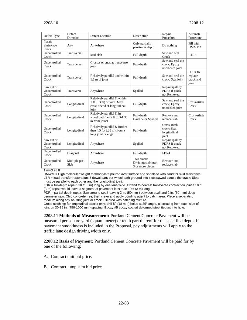
2208.10 2208.12
22-83
Defect Type Defect
Direction Defect Location Description
Repair
Procedure
Alternate
Procedure
Plastic Shrinkage
Crack
Any Anywhere Only partially
penetrates depth Do nothing
Fill with
HMMM2
Uncontrolled Crack
Transverse
Mid-slab Full-depth Saw and seal Crack
LTR³
Uncontrolled Crack
Transverse Crosses or ends at transverse joint
Full-depth
Saw and seal the
crack; Epoxy
uncracked joint
Uncontrolled
Crack Transverse
Relatively parallel and within
1.5 m of joint Full-depth
Saw and seal the
crack; Seal joint
FDR4 to
replace
crack and joint
Saw cut of
Uncontrolled
Crack
Transverse Anywhere Spalled
Repair spall by
PDRS if crack
not Removed
Uncontrolled
Crack Longitudinal
Relatively parallel & within
1 ft (0.3 m) of joint. May
cross or end at longitudinal joint
Full-depth
Saw and seal the
crack; Epoxy
uncracked joint
Cross-stitch
Crack
Uncontrolled Crack
Longitudinal
Relatively parallel & in
wheel path 1-4.5 ft (0.3-1.35
m from joint)
Full-depth, Hairline or Spalled
Remove and replace slab
Cross-stitch Crack
Uncontrolled
Crack Longitudinal
Relatively parallel & further then 4.5 ft (1.35 m) from a
long joint or edge.
Full-depth
Cross-stitch
crack; Seal
longitudinal joint
Saw cut or
Uncontrolled Crack
Longitudinal Anywhere Spalled
Repair spall by
PDRS if crack not Removed
Uncontrolled
Crack Diagonal Anywhere Full-depth FDR4
Uncontrolled
Crack
Multiple per
Slab Anywhere
Two cracks Dividing slab into
3 or more pieces
Remove and
replace slab
1 m=3.28 ft HMWM = High molecular weight methacrylate poured over surface and sprinkled with sand for skid resistance. LTR = load-transfer restoration; 3 dowel bars per wheel path grouted into slots sawed across the crack; Slots must be parallel to each other and the longitudinal joint. FDR = full-depth repair; 10 ft (3 m) long by one lane wide. Extend to nearest transverse contraction joint if 10 ft (3-m) repair would leave a segment of pavement less than 10 ft (3 m) long. PDR = partial-depth repair; Saw around spall leaving 2 in. (50 mm ) between spall and 2 in. (50-mm) deep perimeter saw. Chip concrete free, then clean and apply bonding agent to patch area. Place a separating medium along any abutting joint or crack. Fill area with patching mixture. Cross-stitching; for longitudinal cracks only, drill ¾” (18 mm) holes at 35° angle, alternating from each side of joint on 30-36 in. (750-1000 mm) spacing. Epoxy #5 epoxy coated deformed steel tiebars into hole.
2208.11 Methods of Measurement: Portland Cement Concrete Pavement will be
measured per square yard (square meter) or tenth part thereof for the specified depth. If
pavement smoothness is included in the Proposal, pay adjustments will apply to the
traffic lane design driving width only.
2208.12 Basis of Payment: Portland Cement Concrete Pavement will be paid for by
one of the following:
A. Contract unit bid price.
B. Contract lump sum bid price.

2209.3 2209.3
22-84
SECTION 2209 CURBING
Referenced Standards: The following standards are referenced directly in this section.
The latest version of these standards shall be used.
MCIB
Standard Concrete Specifications
2209.0 General: The term expansion joint, when used in plans, standard drawings or
other specifications shall be understood to mean isolation joint.
2209.1 Summary: This includes the construction or reconstruction of curbing. All
materials and placement shall be tested as outlined in the “Public Works Department
Materials Testing Requirements”.
2209.2 Materials: Materials: Concrete shall conform to 2208..
Material submittals and testing shall conform to Section 2208.
Ready mix concrete shall be supplied by a plant approved by the KCMO Public Works
Department according to the Ready Mix Concrete Quality Management Plan.
2209.3 Construction Details: The curbing shall be constructed or reconstructed to the
configuration and to the lines and grades shown on the plans. Generally the curbing shall
be placed prior to the placement of pavement or sidewalk sections, except when curb and
gutter is integral with the pavement.
During concrete placement, if more than 100 cubic yards is to be placed in a
single day, the contractor shall supply a water tank to cure all test cylinders
infor the first 24 hours after the pour. The tanks shall be of sufficient size to
hold three 4”X8” cylinders for every 50 cubic yards poured that day and to
allow for the water to maintain a temperature between 60ºF and 80ºF after
being filled with water from the ready mix delivery trucks. The contractor shall
be responsible for protecting persons from entering the tanks.
A. Removal of Existing Curbing for Reconstruction: Existing curbing shall be totally
removed to the nearest contraction or expansion joint or with the approval of the
Engineer it may be sawed provided no free section is left that is less than 5 lineal feet
(1.52 m) in length, and provided the entire curbing section is sawed a minimum of 2
inches (5.08 cm) below any exposed surface, or sufficiently to prevent disturbance or
damage to all adjacent structures or slabs, whichever is greater.
B. Grading and Subgrade Preparation: All excavation or embankment shall conform
to Sections 2100 and 2201 entitled "Grading and Site Preparation" and "Subgrade
Preparation" and as follows: Compaction shall conform to Section 2201.3, paragraph
B.

2209.3 2209.3
22-85
C. Forms: All forms shall be in good condition, clean, and free from imperfections.
Each form shall not vary more than 1/4 inch (6 mm) in horizontal and vertical
alignment for each 10 feet (3.0 m) in length.
1. General: Face forms will be used with all curb standards except CG-2 (rollback)
as applicable.
2. Forms shall have a height equal to or greater than the height of the curb face
being formed.
3. The forms shall be set true to line and grade and shall be supported to stay in
position while depositing and consolidating the concrete. The forms shall be
designed to permit their removal without damage to the concrete. The forms shall
be lubricated.
D. Curb Machine: A slip-form curb machine may be used in lieu of forms. The
machine must be equipped with mechanical internal vibrators and be capable of

2209.3 2209.4
22-86
placing curb to the correct cross section, line and grade within the allowable
tolerances.
2209.4 Joints: The joints shall be formed at right angles to the alignment of the curbing
and to the depths specified by the appropriate standard drawing or as shown on the plans.
A. Isolation joints: Isolation joints shall be placed at all radius points, driveways, curb
inlets, or where directed by the plans or Engineer.
1. Material: Isolation joints shall be formed by a one piece, 3/4 inch (19 mm) thick
preformed joint filler cut to the configuration of the correct curb section, and
conforming to Section 2208.2D.
2. Stability: Isolation joints shall be secured in a manner so they will not be
disturbed by depositing and consolidating of concrete.
3. Edging: The edges of the joints shall be rounded with an edging tool of ¼ inch (6
mm) radius.
B. Contraction joints: Curbing shall have contraction joints installed at intervals of not
less than 10 feet (3.05 m) or more than 15 feet (4.57 m). They shall extend through
the entire curb section from the top of the curb to a depth 2 inches (5.0 cm) below
pavement surface.
1. Method: Contraction joints shall be formed or sawed.
a. When sawing joints, the contractor shall begin as soon as the concrete
hardens sufficiently to prevent excessive raveling along the saw cut and shall
finish before conditions induce uncontrolled cracks, regardless of the time or
weather. When joint sealing backup material is specified with sawed joints,
the first stage, which provides a relief cut shall be approximately 1/8 inch (3
mm) wide, and shall be to plan depth. The second stage which widens the
joints to allow the insertion of joint sealing backup material to plan depth
shall not be performed until the concrete is at least 48 hours old, and shall be
delayed longer when the sawing causes raveling of the concrete. If second
stage sawing is performed prior to the completion of the curing period, the
contractor shall maintain the cure by use of curing tapes, plastic devices, or
other materials approved by the engineer.
b. When forming joints, templates shall be 1/8 inch (0.32 cm) metal cut
to the configuration of the curbing section. The templates shall be
secured at the proper locations so that they will not be disturbed by
the depositing of concrete. The templates shall be removed as soon as
the concrete has attained its initial set and finished with a ¼ inch
(0.64 cm) radius on all exposed edges.
2. Joint Sealer: When specified, joint sealants shall conform to Section 2208.2. All
longitudinal joints between the edge of concrete pavement and the curbing shall
be sealed.
2209.5 2209.6
22-87
2209.5 Concrete Work: Concrete for curbing shall be placed in accordance with the
requirements of Section 2208.5. Isolation and contraction joints shall be constructed as
shown on the plans, standard drawings, or where directed by the Engineer.
A. Concrete Placement: Concrete shall be mechanically vibrated except for mixes
with a 4” or greater slump and shall not be allowed to extrude below the
forms to cause an irregular alignment of the abutting street pavement.
B. Finishing: After placing and initial strike-off the curb shall be tooled to the required
radii. If the surface of the concrete is sufficiently wet that a ridge is formed at the
inside of the radius tool, finishing will cease until the excessive moisture has
evaporated.
After initial set, the face forms shall be removed and the surface finished to the
required dimensions. No water, dryer, or additional mortar shall be applied to the free
surface of the concrete.
The finished surface of the concrete shall be broomed perpendicular to the curb with
a clean broom to provide an antiskid surface.
In all cases the finished curb shall have a true surface, free from sags, twists, or
warps, and shall have a uniform color and appearance.
C. Curing: As soon as practical after the concrete is finished it shall be cured with a
liquid curing membrane meeting the requirements of Section 2208.2, applied
according to the manufacturer's directions.
If front and/or back forms are removed from finished curbing within a period of 72
hours of placement these surfaces shall also be cured. Wet burlap, cotton mat,
waterproof paper, polyethylene sheeting or earth backfill is
not an acceptable curing method for curbing.
D. Protection: The Contractor shall protect the concrete work against damage or
defacement of any kind until it has been accepted by the Engineer. Concrete which is
damaged or defaced, shall be removed and replaced, or repaired to the satisfaction of
the Engineer, at the expense of the Contractor.
E. Temperature Limitations: The temperature and humidity shall be taken into
consideration when placing concrete. Steps shall be taken to ensure the concrete
temperature is maintained between 60ºF and 80ºF for at least 3 days after
placement, or it reaches 75% of its design strength, whichever is greater.
F. Repairing Defects: Defects in the concrete shall be repaired in accordance
with 2208.10.
2209.6 Backfill: Backfill shall conform to Section 2208.6. The Contractor shall be
responsible for the repair of any street pavement disturbed by the construction to the
satisfaction of the Engineer.

2210 2210.4
22-88
2209.7 Joint Sealing and Clean-Up: Only the sidewalk portion of the curbing will
require joint sealing, except on concrete streets. An approved joint sealer shall
be applied in accordance with the manufacturer’s directions within 7 days of the
placement of the concrete. The Contractor shall be responsible for the removal of excess dirt, rock, broken concrete,
concrete splatters and overspray from the area of the construction.
2209.8 Surface Tolerances: Curbing shall have a surface tolerance of 1/4 inch (6 mm)
in 10 feet (3 m) when checked with a ten foot (3.05 m) straightedge.
2209.9 Method of Measurement: Curbing will be measured per lineal foot (meter) or
tenth part thereof for the applicable type.
2209.10 Basis of Payment: Curbing will be paid for by one of the following:
A. Contract unit bid price.
B. Contract lump sum bid price.
2210 2210.4
22-89
SECTION 2210 MEASUREMENTS AND PAYMENTS
2210.0 General: The term Bid Form-Unit Prices or Itemized Proposal shall be
understood to mean Proposal.
2210.1 Summary: This section includes the method of measurement and the basis of
payment, for furnishing all labor, equipment, tools and materials and for the performance
of all related work necessary to complete any construction covered in Section 2200.
2210.2 General: Unless specifically altered by the Contract Special Provisions, the
methods of measurement and payment shall be as specified in each section herein, and as
listed in the Proposal.
2210.3 Measurement: The Engineer or his representative will measure the work for
payment. The method of measurement and computations used in determination of
quantities of work performed will be those methods generally recognized as conforming
to good engineering practice.
2210.4 Items not listed in the Proposal: There shall be no measurement or separate
payment for any item of work not specifically identified and listed in the Proposal and all
costs pertaining thereto shall be included in the contract unit prices for other items which
are listed in the Proposal.

2210.4 2210.5
22-90
2210.5 Measurement and Payment Summary Table
Item Description Ref.
Section
Method of
Measurement Basis of Payment
1. Subgrade Preparation 2201 Subsidiary to other item Subsidiary to other
item
2. Untreated Compacted
Aggregate Base 2202
0.1 sq. yd. (0.1 sq. m.)*
0.1 ton (0.1 metric ton)
Unit Bid Price
Lump Sum Bid Price
3. Crushed aggregate Drainable
Base 2203.3
0.1 sq. yd. (0.1 sq. m.)*
0.1 ton (0.1 metric ton)
Unit Bid Price
Lump Sum Bid Price
4. Portland Cement Concrete
Drainable Base** 2203.4
0.1 sq. yd. (0.1 sq. m.)*
0.1 ton (0.1 metric ton)
Unit Bid Price
Lump Sum Bid Price
5. Plan Mix Bituminous
Drainable Base** 2203.5
0.1 sq. yd. (0.1 sq. m.)*
0.1 ton (0.1 metric ton)
Unit Bid Price
Lump Sum Bid Price
6. Pipe Underdrains*** 2203.6 1.0 lineal ft. (0.1 m.) Unit Bid Price
Lump Sum Bid Price
7. Blanket Underdrains*** 2203.6 1.0 lineal ft. (0.1 m.)
0.1 sq. yd. (0.1 sq. m.)
Unit Bid Price
Lump Sum Bid Price
8. Asphalt Prime and Tack Coat 2204 Gallon (liter) Unit Bid Price
9. Asphaltic Concrete Base and
Surface** 2205
0.1 sq. yd. (0.1 sq. m)*
0.1 ton (0.1 metric ton)
Unit Bid Price
Lump Sum Bid Price
10. Asphaltic Crack Seal 2206.3 Pound (kilogram) Unit Bid Price
Lump Sum Bid Price
11. Improved Street Chip Seal** 2206.3 0.1 sq. yd. (0.1 sq. m.) Unit Bid Price
Lump Sum Bid Price
12. Unimproved Street Chip
Seal** 2206.4 0.1 sq. yd. (0.1 sq. m.)
Unit Bid Price
Lump Sum Bid Price
13. Improved Street Slurry Seal 2206.5 0.1 sq. yd. (0.1 sq. m.) Unit Bid Price
Lump Sum Bid Price
14. Improved Street
Microsurfacing 2206.6 0.1 sq. yd. (0.1 sq. m.)
Unit Bid Price
Lump Sum Bid Price
15. Cold Milling 2207 0.1 sq. yd. (0.1 sq. m.) Unit Bid Price
Lump Sum Bid Price
16. Portland Cement Concrete
Pavement 2208 0.1 sq. yd. (0.1 sq. m.)
Unit Bid Price
Lump Sum Bid Price
17. Curbing (Specify the
applicable type) 2209 0.1 ft. (0.1 m.)
Unit Bid Price
Lump Sum Bid Price *Items measured per sq. yd. (sq. m.) shall be listed with the specified depth of material indicated.
**Items may be measured as a single item or as the separate items that comprise the materials.
***Drainable Base Aggregates used with PipeUnderdrains shall be a subsidiary item.
****Blanket Underdrains shall be measured for the actual quantities used, to include Pipe
Underdrains and Drainable Base Aggregate.

2211 2211.3
22-91
SECTION 2211 – SMOOTHNESS
2211.1 Summary: This section includes methods of determining smoothness, and
includes a pay adjustment table where smoothness is required in the contract as a pay
item adjustment.
2211.2 Local Streets & Residential Collectors: Finished pavements on local and minor
collectors shall be checked with a 10 foot (3 meter) straightedge placed parallel to the
center line at any location within a driving lane. Areas showing high spots of more than
1/4 of an inch in 10 feet (6.35 mm in 3 m), shall be marked and ground down with an
approved grinding tool to an elevation where the area or spot will not show surface
deviations in excess of 1/8 inch (3.2 mm) when tested with a 10 foot (3 m) straight edge.
The surface corrections will be done in a manner that produces a surface texture as
similar as possible to the adjacent sections. Grinding will be performed on the full width
of the lane failing to meet the smoothness criteria. The cost of correcting the smoothness
and associated traffic control shall be at contractor’s expense.
2211.3 Arterials and Urban Collectors: If specified, pavement smoothness on arterial
and major collectors will be measured at Contractor’s expense by a 25-foot (7.6-meter)
California profilograph using a .2 inch (5 mm) blanking band, and will follow Table 1. If
profilographs are not specified, Section 2211.2 shall apply. Run one trace three feet (one
meter) from the longitudinal joint between the lanes and another trace three feet (one
meter) from the shoulder or curb edge of the lane. Assure that the profilograph testing
and evaluation is performed by a trained and certified operator. Within two days after the
paving, furnish the Engineer with the profilogram and its evaluation. All pavements will
be corrected at Contractor’s expense to 15 inches per mile (23.7 cm per km).
Table 1 Pay Adjustments
Initial Average
Profilograph measurements
Percent of Contract
Unit Prices
(inches/mile) (cm/kilometer)
0-10 (0-15.8) 105.0
10.1-15 (15.9-23.7) 100.0
15.1-20 (23.8-31.6) 90.0
20.1-25 (31.7-39.6) 80.0
Greater than 25 (39.5) Rejection

2212.3 2212.5
22-92