Digital Sketch Modelling: Integrating digital sketching as ... · blend the use of traditional...
15
Page | 1 Digital Sketch Modelling: Integrating digital sketching as a transition between sketching and CAD in Industrial Design Education Charlie Ranscombe*, Swinburne University of Technology, Australia. Katherine Bissett-Johnson, Swinburne University of Technology, Australia. *Corresponding author e-mail: [email protected] Abstract Literature on the use of design tools in educational settings notes an uneasy relationship between student use of traditional hand sketching and digital modelling tools (CAD) during the industrial design process. This is often manifested in the transition from sketching to CAD and exacerbated by a preference of current students to use CAD. In this research we report the teaching of a new design practice “Digital Sketch Modelling” which combines the strengths of sketching in ideation and CAD in dimensional accuracy while versing students in digital sketching skills that are now expected of graduates going into industry. In doing so we move beyond treating digital sketching as an equivalent of traditional sketching to become a new transitional design tool. This paper sets out the key steps of the Digital Sketch Modelling technique and reports its integration in industrial design curriculum over the last two years. In doing so we contribute a new type of design practice with a research based foundation that answers the requirements of modern industrial design practice. Key words digital sketching, CAD, visual thinking, design sketches 1. Introduction Digitising tablets with pen-based inputs (often known simply as drawing tablets) have become popular and their use widespread across a range of creative and design disciplines. Many industrial design practices now use such hardware regularly in their design process to create digital sketches (defined as 2D images created using the sketch based interface). Use of these digital tools and associated software facilitates greater opportunity for high quality rendering of materials, more
Transcript of Digital Sketch Modelling: Integrating digital sketching as ... · blend the use of traditional...
Page | 1
Digital Sketch Modelling: Integrating digital sketching as a transition between sketching and CAD in Industrial Design Education
Charlie Ranscombe*, Swinburne University of Technology, Australia.
Katherine Bissett-Johnson, Swinburne University of Technology, Australia.
*Corresponding author e-mail: [email protected]
Abstract Literature on the use of design tools in educational settings notes an uneasy relationship between student use of traditional hand sketching and digital modelling tools (CAD) during the industrial design process. This is often manifested in the transition from sketching to CAD and exacerbated by a preference of current students to use CAD. In this research we report the teaching of a new design practice “Digital Sketch Modelling” which combines the strengths of sketching in ideation and CAD in dimensional accuracy while versing students in digital sketching skills that are now expected of graduates going into industry. In doing so we move beyond treating digital sketching as an equivalent of traditional sketching to become a new transitional design tool. This paper sets out the key steps of the Digital Sketch Modelling technique and reports its integration in industrial design curriculum over the last two years. In doing so we contribute a new type of design practice with a research based foundation that answers the requirements of modern industrial design practice.
Key words digital sketching, CAD, visual thinking, design sketches
1. Introduction Digitising tablets with pen-based inputs (often known simply as drawing tablets) have become popular and their use widespread across a range of creative and design disciplines. Many industrial design practices now use such hardware regularly in their design process to create digital sketches (defined as 2D images created using the sketch based interface). Use of these digital tools and associated software facilitates greater opportunity for high quality rendering of materials, more
Page | 2
flexible exploration via a means to “undo” actions, and the ability to generate multiple colour and finish variations to name only a few. The widespread use and availability of these tools requires design education to respond ensuring graduating students are competent in their use (Aldoy & Evans, 2011). This presents both challenges and opportunities for industrial design education. The challenge is in understanding the way in which these tools compliment and contrast traditional hand-sketching techniques (also used in industry) within the design process, and translating this into appropriate exercises/pedagogies that will infer this understanding to students. We perceive the opportunity associated with the use of digital sketching reaching a critical mass in being able to blend the use of traditional analogue sketching and 3d digital modelling tools. In particular we see digital sketching as a means to bridge the troubled waters (further discussed in 2.2) where students transition from traditional sketching to 3d digital modelling (CAD) during student design projects.
The authors acknowledge that there is an existent body of research in computer graphics and HCI fields that explore novel approaches to design tools. Many of these approaches are developed at a lab-based level and take many years to become commercially available tools that are adopted by industry. The intention of the research reported in this paper is in responding to current trends in the use of digital tools (digital sketching and CAD) in design practice and propose a blending of them in order to ease transitions between traditional hand-sketch techniques and 3d digital modelling.
In this paper we describe how we have addressed the challenges and embraced the opportunities within our teaching practice by introducing a digital sketching technique that we refer to as “Digital Sketch Modelling”. We begin by reviewing typical industrial design techniques focusing on the tools of sketching and 3d digital modelling (CAD) and the intentions of their use. In doing so we explore some of the debate relating to these tools, specifically arguments against beginning CAD early in the design process but also acknowledging students’ increasing dexterity and propensity to use CAD. This forms the theoretical foundation used to propose Digital Sketch Modelling as a bridge between the two tools. A review of the characteristics and strengths of digital sketching is then presented with an outline of the Digital Sketch Modelling technique and workflow. Subsequently we describe our approach to teaching Digital Sketch Modelling to industrial design students as a way to blend the strengths of both sketching and CAD modelling during concept design. We then reflect on the teaching of this new design practice outlining challenges faced and improvements made over 2 years of teaching.
2. Background We begin by giving context to the techniques and tools within the typical industrial design process reflected in teaching in traditional studio design projects.
2.1 Visual Representations During the Design Process

Page | 3
A typical industrial design or product design process is set out in Figure 1. This is derived from the industrial design process set out in Ulrich and Eppinger (2008), highlighting the use of sketching and digital representations relevant to this research defined by Pei, Campbell, and Evans (2011).
Figure 1. Illustrating the transition between use of hand sketching and CAD to represent concept designs during the progression of the design process
Key aspects of the process that are of note in this study are the media/tools used to design concepts and the creative intentions at each stage. At the beginning of the process there is an emphasis on the use of traditional hand-sketching widely regarded as a critical aspect of creative thinking in design (Cross, 1982; Lawson, 2002) and a major part of design pedagogies (Oxman, 2008). As the process continues tools are used that embody the design in greater detail and fidelity but requiring the designer to invest more time to create embodiments. In a typical process ambiguous explorative sketches gradually include more detail and are thus more prescriptive of a final design. To further develop details, designers begin working with 3d digital modelling tools often referred to as CAD. This involves making decisions on scale proportion and to some extent manufacturing process and assembly. Thus the outcome is a highly resolved design that can be rendered at photorealistic quality often perceived as being real by the viewer. The authors acknowledge that no design process is necessarily identical to another and that often the process can be iterative between stages and tools used. In the context of design education the limited time available and need to practice the full spectrum of design tools necessitates a more prescriptive process.
The key observation from this generalised design process is the way in which the hand-sketching transitions to the 3d modelling stage as designs develop, however the relatively bipolar nature of sketching (ambiguous and quick) and CAD (detailed but slow) makes this transition far from seamless. These bipolar properties are now discussed in the following section.

Page | 4
2.2 Sketching and CAD As stated above, sketching is widely regarded as a critical aspect of creative thinking in design). Schön (1983) and Goldschmidt (1991) highlight the use of the sketch as a key mechanism to facilitate an iterative thought process where a form of dialogue is created between the sketching action of the designer and perception of the subsequent sketch. One of the key characteristics of the sketch to facilitate this type of process is the freedom with which the designer has to make marks and manipulate representations using pen and paper. A second key characteristic is the ambiguity in sketches (i.e. not fully prescribing or locking in any specific detail) that helps to facilitate the dialogue surrounding the design and question details of the design (Tovey, Porter, & Newman, 2003).
With respect to these qualities of sketching there is speculation of the ability of CAD tools to mimic this type of creative practice. Lawson (2002) first highlights that CAD packages by the nature of complexity in their operation can be restrictive where a user is not highly skilled and the reflective dialogue can be lost. Lawson (2005) further notes that the accuracy of the model can remove ambiguity that instigates the reflective dialogue. Robertson and Radcliffe (2009) echo these thoughts indicating that the enhanced visual quality of models leads to a sense of finality that, on top of lacking ambiguity combined with significant time investment, results in a fixation and unwillingness to make changes to designs.
Tovey et al. (2003) in reviewing the design process (industrial design/automotive) makes a helpful distinction between sketching and CAD with the former being a thinking tool and the latter as a communication tool. This sentiment of “different tools for different jobs” is echoed by Self (2013). Here Self argues that there is a place for both tools and the emphasis is on the designer to use their experience to understand where the relative uses are appropriate. Indeed Robertson and Radcliffe (2009) highlight that experience with CAD tools can help to reduce the negative effects of CAD on creative thinking due to the increased ability to work quickly and easily modify models.
It should be noted that CAD tools for engineering and design have developed rapidly, facilitated by greater computing power, in becoming faster more flexible and more intuitive to use. In particular we refer to the increasing ease of editing models in parametric solid modelling packages such as SolidWorks and direct editing capabilities in surface/NURBS modelling software such as Rhino or Alias (most frequently used by Industrial Design students in the institution that is the focus of this research). While this may be the case Alcaide-Marzal, Diego-Más, Asensio-Cuesta, and Piqueras-Fiszman (2013) state that the flexibility is still far from that of the paper sketch. In particular we observe improvements to work more quickly and be more flexible in making changes to designs, however the designed outcome/model is still highly resolved and thus not ambiguous. Thus despite advances in CAD tools, the bipolar characteristics of CAD and sketching are still evident. While the transition between tools can be overcome with experience, in the context of design education it is not possible to rely on students’ limited experience to guide tool use.
van Passel and Eggink (2013) note a lack of engagement of current students in sketching activities, offering an explanation for this being a preference for CAD tools due to the enhanced visual representation. When compared with the outcomes they are capable of producing by sketching, the high quality visuals produced using CAD can enamour students leading to a preference for the

Page | 5
tools that will produce outcomes that “look the best”. This in turn can lead to an underdevelopment of sketching skills. An additional consideration in this preference for CAD over traditional tools is that many current students can now be considered ‘digital natives’. Current students have spent much of their education and lives using digital tools/devices and unsurprisingly expect to use them and capitalise on their advantages (enhanced visual representation and ability to add detail) over traditional tools/media.
In summary it is clear that there are prominent relative strengths and roles within the design process of both sketching and CAD, thus neither are likely to be replaced by the other. It is also clear that there is still segregation between the two tools and hence the appropriate point for student designers to transition between them requires some experience. In current design education we see a heavy preference by students for CAD over sketching contended to be widespread in many disciplines of design education. Thus the transition and appropriate use of both tools becomes even harder to manage and a major driver for the introduction of digital sketch modelling. As such we see an opportunity for digital sketching to answer the need to ease this this transition by appeasing student desires to use modern technology (overuse of CAD) while maintaining the critical strengths of sketching (freedom and ambiguity).
2.3 Digital sketching Despite the widespread use in industry of digital tablets and digital sketch interfaces becoming standard in entry-level laptops, there is a need to revisit their use in design education (Aldoy & Evans, 2011). Referring to commonly used texts in teaching sketching (Eissen & Steur, 2012; Olofsson & Sjölén, 2007) we see that digital sketching is treated as an analogue of traditional sketch renders (typically detailed sketches applying marker rendering) but with significant functional advantages. The advantages afforded primarily through the software used alongside the digitising tablet are summarised as follows:
• Undo: The designer can easily “undo” any erroneous actions thus strokes do not need to be so deliberate.
• Cut, Paste, Duplicate and Transform: The designer can change elements of a sketch in placement size and rotation. Previously this would require photocopying pages and or physically cutting out parts of sketches.
• Marker/brush and colour flexibility: The designer is able to access an almost infinite range of colours and tones that can be applied with an equally wide range of pens or brushes. Furthermore marks can be made to add both light and dark tones. This flexibility is also available as a means to erase strokes.
• Line templates: Digital tools allow users to generate perfectly straight/smooth lines and curving ellipses rather than relying on hand-eye coordination.
• Layers: Layers provide architecture in the file/sketch being created that allows the designer to apply all of the above tools to individual elements without editing or compromising other parts of the design/sketch.
Page | 6
Generally the result of the increased functionality is in the first instance is in a higher degree of realism that can be achieved than in typical analogue sketching. However with the tools available and subsequent level of realism, the time taken to produce a sketch at this level is longer. Conversely the realism is less than that of a 3d digital model, primarily in the way that the design/representation is only 2d, but also in an inherently sketchy appearance.
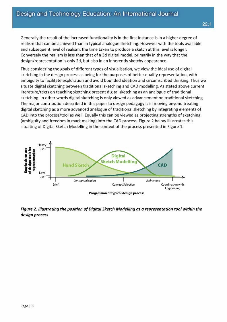
Thus considering the goals of different types of visualisation, we view the ideal use of digital sketching in the design process as being for the purposes of better quality representation, with ambiguity to facilitate exploration and avoid bounded ideation and circumscribed thinking. Thus we situate digital sketching between traditional sketching and CAD modelling. As stated above current literature/texts on teaching sketching present digital sketching as an analogue of traditional sketching. In other words digital sketching is only viewed as advancement on traditional sketching. The major contribution described in this paper to design pedagogy is in moving beyond treating digital sketching as a more advanced analogue of traditional sketching by integrating elements of CAD into the process/tool as well. Equally this can be viewed as projecting strengths of sketching (ambiguity and freedom in mark making) into the CAD process. Figure 2 below illustrates this situating of Digital Sketch Modelling in the context of the process presented in Figure 1.
Figure 2. Illustrating the position of Digital Sketch Modelling as a representation tool within the design process

Page | 7
3. Digital Sketch Modelling Workflow We now discuss the key elements of the digital sketching workflow/method as a means to integrate characteristics of sketching and CAD in a digital sketch setting. The fundamental stages that differentiate the technique from digital sketching and CAD modelling are the use of a “proxy model” and “sketch-over”. We now elaborate each of these and illustrate the complete workflow.
3.1 The Proxy Model The term “Digital Sketch Modelling” is used as to evoke the technique of sketch modelling (Pei et al., 2011) in a digital capacity. In particular we reference use of readily available cheap materials to construct low fidelity models exploring the size and shape of the design concept that can then be augmented with sketches to add further detail. Another analogy can be drawn with the use of maquette figures when sketching or painting figures in portraiture. In this digital approach we begin with the “proxy model”. The proxy model is constructed from “basic forms” usually derived from primitives available in modelling software such as spheres, cones, cuboids and cylinders. These basic forms are then assembled in the modelling software to “block out” an underlying product form echoing the level of detail seen in a physical sketch model or maquette. As with physical sketch modelling the intention is to balance time invested against the fidelity or detail of the model. Simply put, as little time as possible should be spent to represent the design in a capacity where there is the minimum level of detail to reflect on the design and iterate further. The same is the case in Digital Sketch Modelling.
Figure 3. Example of a proxy model and the basic forms typically used to construct them
The authors contend that by using said basic forms to limit the complexity, the enhanced visual quality of models and the ability to add detail that can result in bounded ideation (Robertson & Radcliffe, 2009) is removed. Hence while CAD modelling tools are being used, which may seem counter intuitive having outlined issues associated with use of CAD too early in the design process, we believe we have circumvented some of the causes of these problems through the simplicity of

Page | 8
the proxy model and short time required to produce it. Methods of prescribing the level of detail embodied in the proxy model in the studio setting are discussed further in section 4.
3.2 Sketch Over: Bringing the Proxy Model into a sketching environment The second key component of the Digital Sketch Modelling workflow is the sketch-over. As with the proxy model this draws significant influence from traditional design tools. Here the analogy is of the use of underlays when sketching. Underlay refers to the use of a perspective grid, sketch, photograph, vehicle package or more recently a print out of a 3d model view placed beneath the page being sketched on (Cheng, 2002; Eissen & Steur, 2012; Gahan, 2010; Scott, 2015). This helps the designer by guiding them in the placement of outlines and form lines in the correct perspective and proportion.
In the Digital Sketch Modelling workflow, once a suitable proxy model has been generated, the designer captures views of the model they wish to use in their sketch saving them as 2D images. Figure 4 shows examples of saved 2D views of the proxy model shown in Figure 3. Now that the 2d views are produced the differences from traditional underlays are more apparent centring on some of the key capabilities associated with digital sketching discussed in 2.3.
Figure 4. Examples of two views of a proxy model for a hand drill, rendered and imported into Photoshop
Key capabilities capitalised upon are firstly the use of layers. Here the digital sketch environment in effect allows the user to use an unlimited number of pages (in the form of layers) to sketch over the proxy model. It is also possible to quickly and easily duplicate layers at any stage. This also gives the ability to separate and independently modify parts of or versions of underlays, the result of which is vastly increased flexibility and the speed with which multiple variant designs can be created while still capitalising on the aid of underlays.
The second key addition is in the ability to duplicate colours/shades or even clone sections of the proxy model. Traditional sketching follows a sequence where designers sketch outlines and form lines to represent boundaries and contours. Once these are somewhat established designers use markers or other media to add details to represent surfaces (Tovey et al., 2003). Here the

Page | 9
capabilities from duplicating different tones that represent surfaces allow the designer to work with outlines and surfaces concurrently. This in effect allows the designer to sketch outlines and also represent (sculpt) surfaces simultaneously.
Figure 5. Examples of two variant designs generated from the same proxy model (featured in Figure 3&4) using the digital sketch over technique
Another notable flexibility provided is in way in which the designer has the ability to annotate the sketch with text and motion arrows. While somewhat obvious, the ability to add these semantic properties is raised by Lawson (2002) as being important to sketching as a creative exercise and also noted by Meneely (2007) as a key advantage in digital tablet use. In addition to these more prominent capabilities/differences the advantages set out in 2.3 are still at the designer’s disposal, namely the ability to undo, cut, paste, duplicate, transform elements, and the range of colours tones and brushes at the designer’s disposal.
4. Implementation of Digital Sketch Modelling in Industrial Design Curriculum Having set out the details of the technique we now discuss its implementation in the industrial design curriculum. The Digital Sketch Modelling technique is taught to students during a studio titled “Product Visualisation 3: Digital Sketching and Rendering”. The overall aim of the studio is to teach students digital sketching and advanced rendering techniques. The “3” in the title denotes the way in which this studio is taught following on from previous visualisation studios, thus this studio blends prior (basic) knowledge of both traditional sketching and CAD. The studio runs for 12 weeks of which the first five weeks focus on learning the basics of digital sketching using a digitising tablet (in this case a Wacom 24HD Cintiq) with Adobe Photoshop. The subsequent 4 weeks are dedicated to Digital Sketch Modelling and the final two weeks focus on rendering software for 3d digital models. This syllabus is illustrated in Figure 6.

Page | 10
Figure 6. Timeline and activities during the subject in which Digital Sketch Modelling is taught
4.1 Digital Sketch Modelling Pedagogy One week prior to the Digital Sketch Modelling stage (week 6 in the semester) students are given a design brief. In the first year this was a power tool, in the second the brief was open. In the first stage of the project students are required to create a range of sketches exploring different concepts. Here digital sketching is used to practice techniques taught during the fundamentals stage of the process. At this stage the sketching is largely still an analogue of traditional hand-sketching as per techniques set out in (Eissen & Steur, 2012; Olofsson & Sjölén, 2007). Over weeks 7 and 8 students begin by developing a proxy model to represent their chosen concept and go on to create 3 variant designs for the concept via sketch-over on views of their proxy model. The final week is spent further refining one variation by adding further shape details, colour and material finishes. This final design variation is the basis for a presentation panel that forms the final outcome of the digital sketch modelling process along with a folio including all Digital Sketch Modelling work leading up to this point.
4.2 Implementation: Year 1 Discussion & Feedback The delivery in class and student engagement with the technique is now discussed. The clearest feedback from students was spelling out the way in which having a proxy model to sketch over helped them to understand and create the correct 3d perspective. Poor perspective was noted at the outset of the unit as being a problem area for students when going through the digital sketch fundamentals. A typical student response suggested that where students often knew from looking at sketches that some aspect of their perspective was incorrect but didn’t know what, the proxy model helped to show this very quickly.

Page | 11

Page | 12
Figure 7. from both 1st and 2nd year of teaching the technique Example student projects showing proxy models (i) and final designs (ii).
In a similar manner students noted that the proxy model also helped to define the correct tonal value to apply to accurately reflect surface geometry through the ability to replicate colours (colour picker/eyedropper tool).
The major challenges observed by educators related to the way in which students approached the proxy model. Students were encouraged to use a simplistic proxy model. During the course of teaching it was seen that many students where going beyond this suggested level of detail (See Figure 7 a)i) and a)ii) for example). This showed that students were relying on CAD modelling to create their design rather than sketching it. When probed as to why they took this course of action, many students indicated they found it easier and the outcome “looked better”. Consequently it was observed during grading the degree of difference from proxy to final concept was far less than expected where over-detailed proxy models were used compared with more simplistic proxy models (see again Figure 7 ai) and a)ii)). These observations concur with those of Robertson and Radcliffe (2009) in demonstrating the way in which students were still enticed into CAD modelling by the enhanced visual quality and as a consequence their ideation was bounded.
Another factor in this observation is that students had received training in CAD software and also used it independently in previous studio projects. Conversely this studio was the first time students were introduced to digital sketching. Thus it is suggested that students were deferring to the media/tools that they felt were easier to use. Again, when probed as to how they defined easy to use, students focused on ease with which they could produce enhanced visual outcomes. In other words there was a strong temptation to over refine their proxy model in CAD because creating equivalent detail via sketch was harder and that the result was deemed by students to have weaker visuals.
4.3 Implementation: Year 2 Discussion & Feedback Following on from observations of student engagement and outcomes, a number of adjustments were made to the delivery of the technique for the second year. The major change made was in the level of detail used in the proxy models. Students were instructed to use a maximum of 5 basic forms placed in any arrangement to create the proxy model. The second adjustment was specifying the modelling software for students to use in creating the proxy model. In the first year many students used solid modelling software (SolidWorks) where in the second year students were encouraged to use surface modelling software (Rhino). This software had the increased flexibility and ease to arrange basic forms. It was also software students were less familiar with and hence less likely to have the capability to over-refine their models.
While some stronger students embraced these rules with highly rated outcomes (See Figure 7 d) and e) for examples), there were still instances of over refining proxy models and barely applying digital sketching skills (see Figure 7 b)). A further observation was in the nature of the variations students designed from their proxy model. It was seen that some students appeared to be bound by the overall volumes/geometry of their proxy model and would only sketch variations in graphical details such as buttons, lights or material finishes (see Figure 7 c)) while others explored more form based variations as well as graphical elements (see Figure 7 d) and e)).
Page | 13
The expectation running the class for the second time was that the inherent ambiguity of simplistic proxy models would automatically stimulate students into greater explorations of form. The outcomes suggest that this is the case for some students, however others retain a simplistic form and only explored graphical elements. Thus a consideration going forward is how to teach the technique in such a way that encourages students to explore both form and graphical elements.
Feedback from students further corroborated that from the first year of teaching regarding the way the technique helped to train perspective and tone. While there were still students indicating they would prefer to use CAD alone to create designs, there were more students indicating that they would find it difficult and time consuming to create their final designs and indicated the forms and finishes they had created represented concepts far beyond their current 3d modelling capabilities. This was seen as a major breakthrough in understanding the technique and battling issues of circumscribed thinking that can occur through over reliance on CAD.
5. Conclusion In this paper we describe how we teach the Digital Sketch Modelling technique as an approach to digital sketching that bridges opposing strengths in traditional sketching techniques and CAD. Through a survey of the literature we have explored the relative strengths and weaknesses of both CAD and sketching and shown that there is a need in education to bridge the way in which both are considered and applied during a typical industrial design process. In describing the technique we conclude with a number of key benefits of its use. These are summarised as:
• Embracing a technology that is widely used in industry but under used in education, also accounting for the fact that students are digital natives and expect to capitalise on digital tools when they are available.
• Maintaining the freedoms of sketching while capitalising on enhanced visual properties (materials, surface finishes, graphical elements).
• Using the readily available 3d forms from CAD as a means to assist student’s ability in sketching visualisations. Namely to create accurate perspective and use appropriate tonal variation to communicate 3d form.
In doing all of the above we believe we make a significant contribution in providing a new research based approach to digital ideation answering calls integrate digital sketching into design curricula. Furthermore the experiences of this studio lead to a secondary conclusion that there is a need to more rigorously communicate the intentions of different tools’ uses through the design process and when it is appropriate to use them.
We acknowledge that there is now a need to conduct further research into digital sketch modelling. Firstly a follow up study on the way students apply the technique in subsequent studio design projects where tools at their disposal are less prescribed is needed. This is expected to be in the form of a review where folio work from subsequent studios is analysed for application of the technique. At a foundational level there is a need to formally experiment with the use of the technique against a control in order to make more generalizable claims on the benefits of using the technique. There is also a need to test the breadth of ideas that are produced with respect to the relative simplicity (ambiguity) of proxy models. This would help to elaborate the level of detail in
Page | 14
the proxy model that is ideal for producing a wide breadth of ideas/variations during concept development. This could also be extended to compare experienced designers’ use of the technique compared with that of students. Findings in this test would also help in exploring whether this technique functions best as a stand-alone design tool or rather an educational scaffold to assist students in learning how to apply skills in sketching (digital and traditional) and CAD.
Acknowledgements
The Authors would first like to acknowledge Bryan Lee for his help in developing and delivering the Digital Sketch Modelling pedagogy in studio classes. The authors would also like to thank the reviewers for their insightful comments on earlier drafts of this article.
6. References Alcaide-Marzal, J., Diego-Más, J. A., Asensio-Cuesta, S., & Piqueras-Fiszman, B. (2013). An exploratory study on the use of digital sculpting in conceptual product design. Design Studies, 34(2), 264-284.
Aldoy, N., & Evans, M. (2011). A review of digital industrial and product design methods in UK higher education. The Design Journal, 14(3), 343-368.
Cheng, N. (2002). Introduction to Architectural Computer Graphics: Assignment 4. Retrieved from http://pages.uoregon.edu/graphics/2002/assign/610.02-as4.html
Cross, N. (1982). Designerly ways of knowing. Design Studies, 3(4), 221-227.
Eissen, K., & Steur, R. (2012). Sketching: Basics, Stiebner Verlag GmbH.
Gahan, A. (2010). 3D Automotive Modeling: An Insider's Guide to 3D Car Modeling and Design for Games and Film. Taylor & Francis.
Goldschmidt, G. (1991). The dialectics of sketching. Creativity research journal, 4(2), 123-143.
Lawson, B. (2002). CAD and creativity: does the computer really help? Leonardo, 35(3), 327-331.
Lawson, B. (2005). Oracles, draughtsmen, and agents: the nature of knowledge and creativity in design and the role of IT. Automation in construction, 14(3), 383-391.
Meneely, J. (2007). Motive, mind, and media: Digital sketching in the creative culture of design. Journal of Interior Design, 32(3), 69-90.
Olofsson, E., & Sjölén, K. (2007). Design sketching. KEEOS Design Books.
Oxman, R. (2008). Digital architecture as a challenge for design pedagogy: theory, knowledge, models and medium. Design Studies, 29(2), 99-120.

Page | 15
Pei, E., Campbell, I., & Evans, M. (2011). A taxonomic classification of visual design representations used by industrial designers and engineering designers. The Design Journal, 14(1), 64-91.
Robertson, B., & Radcliffe, D. (2009). Impact of CAD tools on creative problem solving in engineering design. Computer-Aided Design, 41(3), 136-146.
Schön, D. A. (1983). The reflective practitioner: How professionals think in action (Vol. 5126): Basic books.
Scott, A. (Producer). (2015, 17.9.2015). 3D models for sketch underlays. [Movie] Retrieved from https://www.youtube.com/watch?v=sBaw79VfUfQ
Self, J. A. (2013). CAD Tools and Creative Design, Grounds for Divorce or Match Made in Heaven? CAD/CAM Review, 19(2), 36-43.
Tovey, M., Porter, S., & Newman, R. (2003). Sketching, concept development and automotive design. Design Studies, 24(2), 135-153.
Ulrich, K., & Eppinger, S. (2008). Product design and development (4th ed.). London: McGraw-Hill.
van Passel, P., & Eggink, W. (2013). Exploring the influence of self-confidence in product sketching. Paper presented at the 15th International Conference on Engineering and Product Design Education: Design Education-Growing our Future.
About the Authors:
Charlie Ranscombe is a lecturer in Industrial Design at Swinburne University of Technology, Melbourne Australia. Charlie’s research primarily focuses in product aesthetics and strategic product styling. Charlie also has interests in digital design tools and digital sketching.
Kate Bissett-Johnson’s interest in Design Process and Design Methods Tools has been continually refined through research and teaching practice. She currently teaches Industrial Design, blending this knowledge with the practice of Design through the use of experiential learning.