Development Status of Canon’s EUVL Exposure Tool · Development Status of Canon’s EUVL Exposure...
19
Development Status of Development Status of Canon’s EUVL Exposure Tool Canon’s EUVL Exposure Tool Akira Miyake, Chidane Ouchi, Hid ki M i hi d Hi hi Kb Hideki Morishima, and Hiroyoshi Kubo Canon Canon Inc Inc Canon Canon Inc. Inc. International EUVL Symposium, October 18 2010, Kobe Slide 1
Transcript of Development Status of Canon’s EUVL Exposure Tool · Development Status of Canon’s EUVL Exposure...

Development Status of Development Status of Canon’s EUVL Exposure ToolCanon’s EUVL Exposure Tool
Akira Miyake, Chidane Ouchi, Hid ki M i hi d Hi hi K bHideki Morishima, and Hiroyoshi Kubo
CanonCanon IncIncCanon Canon Inc. Inc.
International EUVL Symposium, October 18 2010, Kobe Slide 1

OutlineOutlineEUVL Exposure tool Roadmap
O ti E l ti T h l iOptics Evaluation Technologies•Multilayer Evaluation•Wavefront Error (WFE) Measurement•Wavefront Error (WFE) Measurement
Evaluation Results of PO1 MirrorsS f Fi• Surface Figure
• Multilayer (phase shift distribution)
O ti l P fOptical Performance• WFE and Resolution• High-NA Projection Optics• High-NA Projection Optics
Exposure System TechnologiesS t l it filt (SPF)• Spectral purity filter (SPF)
• Optics Contamination Mitigation
SInternational EUVL Symposium, October 18 2010, Kobe Slide 2
Summary

EUVLEUVL Exposure Tool RoadmapExposure Tool Roadmap
ITRS2009 2009 2010 2011 2012 2013 2014 2015 2016 2017 2018 2019DRAM 1/2pitch (nm)Flash 1/2pitch (nm)
52 45 40 36 32 28 25 23 20 18 1638 32 28 25 23 20 18 16 14 13 11
HVMHVM tool (VS2)NA 0.33 OAI
PlatformHVM tool (VS3)NA > 0.4 TP Enhancement
Timing of the HVM tools is under consideration.
SFETInstalled at SELETE
Prototype 6-mirror (PO1) NA0.3Prototype ( )In-house test
International EUVL Symposium, October 18 2010, Kobe Slide 3

AtAt--wavelength Multilayer Evaluation Systemwavelength Multilayer Evaluation SystemEvaluation Technology
EUV sourceMirror chamber Monochromator ControllerSample chamber
Polarization controlPhase measurementReflectivity measurement
M1 M3
Polarization control
Multilayer Surface
Incident Beam
Reflected Beam
Phase measurement Reflectivity measurement
Measured Reflectivity
P-polSample
RotationM2
Mo Si Mo SiSi Mo Si MoVacuum
2
3
4
Fiel
d In
tens
ity
Photoelectrons
S-polh t l t i t it d d h diff
0
1
-14 -7 0 7 14 21 28
Elec
tric
Depth (nm)
International EUVL Symposium, October 18 2010, Kobe Slide 4
extinction factor <1E-3photoelectron intensity depends on phase difference between incident beam and reflected beam.
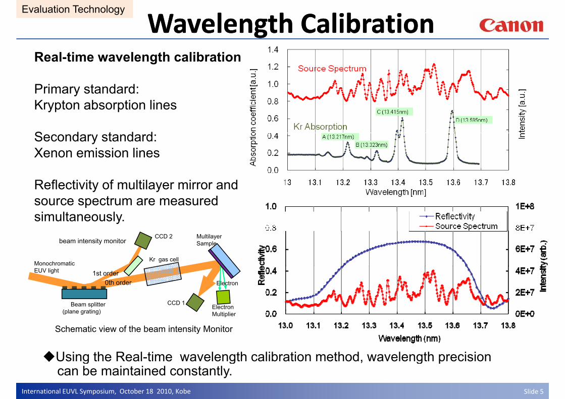
Wavelength CalibrationWavelength CalibrationEvaluation Technology
Real-time wavelength calibration
Primary standard:Primary standard: Krypton absorption lines
S d t d dSecondary standard: Xenon emission lines
Reflectivity of multilayer mirror and source spectrum are measured simultaneously.y
Monochromatic
CCD 2 Multilayer Samplebeam intensity monitor
Kr gas cell
EUV light
Beam splitter ( l ti )
Electron CCD 1
Electron 0th order1st order
Schematic view of the beam intensity Monitor
(plane grating) Multiplier
Using the Real time wavelength calibration method wavelength precision
International EUVL Symposium, October 18 2010, Kobe Slide 5
Using the Real-time wavelength calibration method, wavelength precision can be maintained constantly.

EUV EUV ReflectometerReflectometer RoundRound--RobinRobinEvaluation Technology
EUV reflectometer cross calibration (Round-Robin) conducted by Selete
ti i t S l t C HOYA NIKON PTBparticipant: Selete, Canon, HOYA, NIKON, PTB
S-pol.θ = 6deg
Difference between Canon and PTBCWHM : <1pmCWHM : 1pmPeak Reflectivity : <0.2%
Measurement results by Canon and PTB show good agreement.
International EUVL Symposium, October 18 2010, Kobe Slide 6
Poster:ML-P05 M. Amemiya et al., Selete, Canon, HOYA, NIKON, PTB

WFE measurement using low brightness sourceMISTI (M lti I h t S T lb t I t f t )T lb t I t f t
Evaluation Technology
MIS MaskMISMask
(Pinhole arrays)
MISTI (Multi Incoherent Source Talbot Interferometer)
Single Pinpole
Talbot Interferometer(conventional)
Illumination Optics
Spherical wave from pinhole arrays
spherical wave
PO PO
Projection Optics
p yare incoherent.PO
Distorted spherical wave
PO
Optics
EUV Source
2-D Grating
2-D Grating
p
Source
Grating Waferfringe pattern fringe pattern
Wafer ChuckCCD
Changeable
Position of fringe pattern is maintained. EUV flux is multiplied by number of the pinholes.( X105 )
Wavefront error of the PO can be derived from analyze of the
WFE of PO can be measured using light source for exposure
Changeablepyfringe pattern.
International EUVL Symposium, October 18 2010, Kobe Slide 7
g g pApplicable for on-machine measurement of projection optics WFE

Experimental results of WFE MeasurementEvaluation Technology
EUVEUVsource
Optics ChamberChamber
Experimental Tool using 2-Mirror PO
Fringe patternRepeatability of WFE:0 028nmRMS g pexposure time : 5sec
WFE was measured 3 times. Optical0
0.2
0.4 1st2nd3rd
Repeatability of WFE:0.028nmRMS
WFE was measured 3 times. Opticalelements (MIS mask, Grating, Illuminator) are re-aligned for each measurement.
5 10 15 20 25 30 35-0.2
0
Zernike coefficient
WFE of a PO was measured using a compact DPP source.Repeatability of WFE : 28 pm rms
International EUVL Symposium, October 18 2010, Kobe Slide 8
This experiment was performed as a collaboration work of Canon, Nikon and University of Electro-Communications.

Mirror Surface AccuracyMirror Surface AccuracyResults of PO1 Mirrors
Surface roughness Map
⑥NA
Power Spectrum Density
1E-3
1E-2
1E-1
*mm
]
Mirror No 2
Figure: 40pmRMS
MSFR: 61pmRMS+5nm
60m
m
80m
m
②
⑤
④ ⑦
⑥
1E-5
1E-4
1E 3
er[n
m2 * Mirror No.2
-5nm
Range
16
120mmFigure: 38pmRMS
MSFR: 53pmRMS
+0.5
nm
28
①
③
④ ⑦
⑧
1E-7
1E-6
Pow
e
HSFR: 74pmRMS
Mirror No.1HSFR: 65pmRMS
+5nm
0mm
Measured roughness (pmRMS)
-0.5
nm
250mm
1E-9
1E-8
0.01 0.1 1 10 100 1000 10000
Spatial Frequency [1/mm]
HSFR: 65pmRMS
-5nm
Range
60mm
80
AreaMeasuring Point
Average① ② ③ ④ ⑤ ⑥ ⑦ ⑧
Φ5.0mm 41 41 51 41 40 42 41 45 43
Measured roughness (pmRMS)
Spatial Frequency [1/mm]Φ0.77mm 55 56 56 55 56 60 58 60 57Φ0.15mm 35 34 36 35 37 38 41 38 37
Improved polishing technology on large-area EUV mirrors have been demonstrated.The technology meet the 5% flare specification in 4 5 decades in spatial
International EUVL Symposium, October 18 2010, Kobe Slide 99
The technology meet the 5% flare specification in 4.5 decades in spatial frequency.

Mo/Si multilayer coatingMo/Si multilayer coatingResults of PO1 Mirrors
Multilayer thickness distribution and reflection phase shift distribution of a mirror
radial position
reflection phase shift distribution of a mirror of projection optics were evaluated.
ML Thickness Distribution Phase Shift Distribution
Thickness variation ≦0.032% Uncorrectable phase error ≦2mλThickness variation ≦0.032%
Multilayer Coating performance necessary for HVM
Uncorrectable phase error ≦2mλ
International EUVL Symposium, October 18 2010, Kobe Slide 10
y g p yexposure tool is achieved.

WavefrontWavefront Error of a 6Error of a 6--Mirror Projection OpticsMirror Projection OpticsOptical Performance
Wavefront error of 0.33NA projection optics is estimated based on evaluation results of PO1 Mirrors. In the estimation, following factors areevaluation results of PO1 Mirrors. In the estimation, following factors are considered.
• mirror surface figure errors based on measured data of PO1 mirrorti b d d d t f PO1 i• coating errors based on measured data of PO1 mirror
• alignment errors of mirrors (positions, tilt)
Estimated wavefront error (WFE) Map
2mm
26mm
International EUVL Symposium, October 18 2010, Kobe Slide 11
Z4-36RMS (worst) : 0.5 nm for 33 fields

Optical Performance
Estimated performance for hp16nmEstimated performance for hp16nm
1
NA0.33 PO with Off Axis Illumination (OAI)Illumination condition
2 0
0.2
0.4
0.6
0.8
1
σout=0.8σin =0.5 1.5
2.0 x hgt= 1x hgt= 2x hgt= 3x hgt= 4x hgt= 5
h t 6200
-0.8
-0.6
-0.4
-0.2
0
1.0
NIL
S
x hgt= 6x hgt= 7x hgt= 8x hgt= 9x hgt= 10x hgt= 11y hgt= 1
200nm
-1 -0.5 0 0.5 1-1
0.0
0.5 y hgt= 2y hgt= 3y hgt= 4y hgt= 5y hgt= 6y hgt= 7y hgt= 8
-150 -100 -50 0 50 100 150Focus(nm)
y gy hgt= 9y hgt= 10y hgt= 11
PatternL/S=16 nm
DOF >200nm for NILS>1.2 (16nm pattern )
Performance of NA0.33 PO was estimated.P di t d l ti i h f 16 tt i ti
International EUVL Symposium, October 18 2010, Kobe Slide 12
Predicted resolution is enough for 16nm pattern printing.

High NA PO Design High NA PO Design Optical Performance
NA0.5NA0.5NANA≧≧0 400 40
NA0.25NA0.25 NA0.3NA0.3
NANA≧≧0.400.40
NANA≧≧0.300.30
8 mirrors
6 mirrors
4 mirrors
NANA0.2 0.3 0.4hp32 hp23 hp16 hp11
International EUVL Symposium, October 18 2010, Kobe Slide 13

System Technology
Spectral Purity of LPP SourceSource Charqacteristic Requirement
Spectral purity:
Spectral purity part of “Joint Requirements for EUV Source”
“Joint Requirements for EUV Source” Nikon, ASML, Canon EUVL symposium 2009
130-400 [nm] (DUV/UV)
≥400 [nm] (IR/Vis) including 10.6 μm (3)
<1% at wafervalues at IF-design dependent<10 – 100% at wafervalues at IF-design dependent
(3) Assuming 10.6 mm being the excitation laser wavelength
Measured out-of-band spectrumParameter, Dimension Measurement conditions or
Measured Data
OOB EUV (5-130nm excluding On Band ) at IF 3.3% for EUV band from 9 to 21 nm
DUV(130-400nm) 40-70% of IB in plasma Cymer Inc Igor V FomenkovU ( 30 00 ) 0 0% o p as a(extrapolation of exponential fit)
VIS-NIR(400nm-1.5 mm) 6% of IB in plasma.MLM has low R for this band
IR (1 10 ) 0 01% i l i i l fi
Assumptions10 6mmradiation at IF : 50%
Cymer Inc. Igor V. Fomenkovet al, Proc. SPIE 7271-119
IR (1.5-10μm) <0.01% in plasma using exponential fit
10.6μm Reflection 50% of Inband EUV
10.6mmradiation at IF : 50% (ratio to in-band EUV)Mirror [email protected] : 65%Mirror [email protected]μm : 90%Number of reflection : 12Estimated IR power @ wafer is 25X of in band EUV
Spectral purity filter eliminating 10.6μm radiation
Number of reflection : 12Estimated IR power @ wafer is 25X of in-band EUV.
International EUVL Symposium, October 18 2010, Kobe Slide 14
is needed for CO2 Laser LPP source.

Spectral Purity FilterSystem Technology
Reflection type spectral purity filter (ML coated blazed grating)20 8
dsinα - dsinβ = mλ
0.9
1
45
50
強度分布
0次 1次
20
b) 6
7
8
13.5nm
m=380dsinα dsinβ mλ
α = 15degd = 50μm
13.5nm
10.6μmα β
0.5
0.6
0.7
0.8
20
25
30
35
40
系列1
EUV
0次回
折d 80umα 7degθ 2degN 10
0次 1次
4°3.6°
10
nte
nsi
ty (ar
b
3
4
5
10.6μm
m=0m=1
θ = 3deg10.6μm
50μm
θ
d
Grating Parameters0
0.1
0.2
0.3
0.4
-5
0
5
10
15
-20 -15 -10 -5 0 5 10 15 20
N 10
0
In
0
1
2
m=-1
Incident angle αDiffraction angle βGrating pitch d
g050
0 5 10 15 20 25 30Diffraction Angle (deg)
0
g pBraze angle θDiffraction order m
A reflection type blazed grating can work as a spectral purity filter eliminating 10.6μm radiation.Ad t f h t l d d bilit
International EUVL Symposium, October 18 2010, Kobe Slide 15
Advantage of heat load durability
System Technology
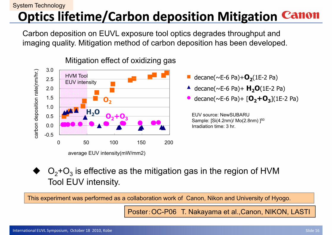
Optics lifetime/Carbon deposition MitigationOptics lifetime/Carbon deposition MitigationCarbon deposition on EUVL exposure tool optics degrades throughput and imaging quality. Mitigation method of carbon deposition has been developed.
Mitigation effect of oxidizing gas
2 5
3.0
m/h
r.)
decane(~E-6 Pa)+O2(1E-2 Pa)HVM Tool
1.5
2.0
2.5
tion
rate
(nm decane(~E 6 Pa)+O2(1E 2 Pa)
decane(~E-6 Pa)+ H2O(1E-2 Pa)
decane(~E-6 Pa)+ [O2+O3](1E-2 Pa)
EUV intensity
O2
0.0
0.5
1.0
bon
depo
sit
EUV source: NewSUBARUSample: [Si(4.2nm)/ Mo(2.8nm) ]50
Irradiation time: 3 hr.
H2O O2+O3
-0.5 0 50 100 150 200
carb
average EUV intensity(mW/mm2)
O2+O3 is effective as the mitigation gas in the region of HVM Tool EUV intensityTool EUV intensity.
This experiment was performed as a collaboration work of Canon, Nikon and University of Hyogo.
International EUVL Symposium, October 18 2010, Kobe Slide 16
Poster:OC-P06 T. Nakayama et al.,Canon, NIKON, LASTI

SummarySummary
Key technologies for HVM EUVL exposure tools have been developed.
• Multilayer evaluation (reflectivity, phase shift)
• Wavefront measurement using low brightness source
• Mirror figuring and ML deposition satisfying HVM tool requirementsMirror figuring and ML deposition satisfying HVM tool requirements
• Reflection type spectral purity filter
• Mitigation of carbon deposition
Timing of HVM EUVL exposure tools is under consideration.
International EUVL Symposium, October 18 2010, Kobe Slide 17

AcknowledgmentAcknowledgment
Parts of this work were performed under the management ofParts of this work were performed under the management of
Extreme Ultraviolet Lithography System Development Association
(EUVA) in the Ministry of Economy Trade and Industry program
supported by New Energy and Industrial Technology Developmentsupported by New Energy and Industrial Technology Development
Organization (NEDO).
International EUVL Symposium, October 18 2010, Kobe Slide 18

Thank you for your attention!Thank you for your attention!y yy y
International EUVL Symposium, October 18 2010, Kobe Slide 19