
Development of space-based diffractive telescopes
19
Zhao et al. / Front Inform Technol Electron Eng 2020 21(6):884-902 884 Development of space-based diffractive telescopes * Wei ZHAO 1,3,4 , Xin WANG †‡1 , Hua LIU †‡2,4 , Zi-feng LU 2,4 , Zhen-wu LU 5 1 School of Science, Changchun University of Science and Technology, Changchun 130022, China 2 School of Physics, Northeast Normal University, Changchun 130024, China 3 Jilin Police College, Changchun 130117, China 4 Key Laboratory of Spectral Imaging Technology, Xi’an Institute of Optics and Precision Mechanics, Chinese Academy of Sciences, Xi’an 710119, China 5 Changchun Institute of Optics, Fine Mechanics and Physics, Chinese Academy of Sciences, Changchun 130024, China † E-mail: [email protected]; [email protected] Received Sept. 28, 2019; Revision accepted Feb. 24, 2020; Crosschecked Mar. 17, 2020; Published online Apr. 14, 2020 Abstract: Membrane diffractive optical elements formed by fabricating microstructures on the substrates have two important characteristics, ultra-light mass (surface mass density < 0.1 kg/m 2 ) and loose surface shape tolerances (surface accuracy requirements are on the order of magnitude of centimeter). Large-aperture telescopes using a membrane diffractive optical element as the primary lens have super large aperture, light weight, and low cost at launch. In this paper, the research and development on space-based diffractive telescopes are classified and summarized. First, the imaging theory and the configuration of diffractive-optics telescopes are discussed. Then, the developments in diffractive telescopes are introduced. Finally, the development prospects for this technology used as a high-resolution space reconnaissance system in the future are summarized, and the critical and relevant work that China should carry out is put forward. Key words: Membrane diffractive optical elements; Diffractive telescope; Super large aperture https://doi.org/10.1631/FITEE.1900529 CLC number: O439 1 Introduction In 1990, the Hubble Space Telescope was launched into space in the USA, with an aperture of 2.4 m (Allen et al., 1990; Williams RE et al., 1996; Freedman et al., 2001). Since 1992, many KH-12 space reconnaissance cameras have been put into orbit, with the maximum diameter being 3.8 m. In 2002, the launch of the James Webb Space Telescope System in 2011 was planned; however, it was then postponed to 2021 because of the difficulties in manufacturing and adjustment. The aperture of the primary lens was also reduced from the original 8 to 6.5 m (Feinberg, 2004; Gardner et al., 2006; Freese et al., 2010; Clampin, 2012). Throughout the develop- ment of large-aperture space telescopes, it has taken nearly three decades to upgrade the optical systems with the aperture increasing from 3.8 to 6.5 m. With the increase of aperture and the complexity of space- based optical systems, the detection difficulty and the cost of launch are growing exponentially. It can be seen that it is difficult to develop a large-aperture spatial optical remote sensor using the conventional reflective optical system. At present, three methods have been developed to solve this problem: 1. Space block self-assembly technology On the ground, the large-aperture reflection primary lens is divided into many lightweight mirrors that have small aperture, and they are launched into space one after another. Then, they are unfolded and stitched to form the telescope system in space. Frontiers of Information Technology & Electronic Engineering www.jzus.zju.edu.cn; engineering.cae.cn; www.springerlink.com ISSN 2095-9184 (print); ISSN 2095-9230 (online) E-mail: [email protected] Review: ‡ Corresponding authors * Project supported by the National Natural Science Foundation of China (No. 11874091) ORCID: Wei ZHAO, https://orcid.org/0000-0002-5009-5816; Xin WANG, https://orcid.org/0000-0003-1102-1301; Hua LIU, https://orcid.org/0000-0003-1455-8948 © Zhejiang University and Springer-Verlag GmbH Germany, part of Springer Nature 2020
Transcript of Development of space-based diffractive telescopes
Zhao et al. / Front Inform Technol Electron Eng 2020 21(6):884-902 884
Development of space-based diffractive telescopes*
Wei ZHAO1,3,4, Xin WANG†‡1, Hua LIU†‡2,4, Zi-feng LU2,4, Zhen-wu LU5
1School of Science, Changchun University of Science and Technology, Changchun 130022, China 2School of Physics, Northeast Normal University, Changchun 130024, China
3Jilin Police College, Changchun 130117, China 4Key Laboratory of Spectral Imaging Technology, Xi’an Institute of Optics and Precision Mechanics,
Chinese Academy of Sciences, Xi’an 710119, China 5Changchun Institute of Optics, Fine Mechanics and Physics, Chinese Academy of Sciences, Changchun 130024, China
†E-mail: [email protected]; [email protected] Received Sept. 28, 2019; Revision accepted Feb. 24, 2020; Crosschecked Mar. 17, 2020; Published online Apr. 14, 2020
Abstract: Membrane diffractive optical elements formed by fabricating microstructures on the substrates have two important characteristics, ultra-light mass (surface mass density < 0.1 kg/m2) and loose surface shape tolerances (surface accuracy requirements are on the order of magnitude of centimeter). Large-aperture telescopes using a membrane diffractive optical element as the primary lens have super large aperture, light weight, and low cost at launch. In this paper, the research and development on space-based diffractive telescopes are classified and summarized. First, the imaging theory and the configuration of diffractive-optics telescopes are discussed. Then, the developments in diffractive telescopes are introduced. Finally, the development prospects for this technology used as a high-resolution space reconnaissance system in the future are summarized, and the critical and relevant work that China should carry out is put forward. Key words: Membrane diffractive optical elements; Diffractive telescope; Super large aperture https://doi.org/10.1631/FITEE.1900529 CLC number: O439 1 Introduction
In 1990, the Hubble Space Telescope was
launched into space in the USA, with an aperture of 2.4 m (Allen et al., 1990; Williams RE et al., 1996; Freedman et al., 2001). Since 1992, many KH-12 space reconnaissance cameras have been put into orbit, with the maximum diameter being 3.8 m. In 2002, the launch of the James Webb Space Telescope System in 2011 was planned; however, it was then postponed to 2021 because of the difficulties in manufacturing and adjustment. The aperture of the
primary lens was also reduced from the original 8 to 6.5 m (Feinberg, 2004; Gardner et al., 2006; Freese et al., 2010; Clampin, 2012). Throughout the develop-ment of large-aperture space telescopes, it has taken nearly three decades to upgrade the optical systems with the aperture increasing from 3.8 to 6.5 m. With the increase of aperture and the complexity of space- based optical systems, the detection difficulty and the cost of launch are growing exponentially. It can be seen that it is difficult to develop a large-aperture spatial optical remote sensor using the conventional reflective optical system. At present, three methods have been developed to solve this problem:
1. Space block self-assembly technology On the ground, the large-aperture reflection
primary lens is divided into many lightweight mirrors that have small aperture, and they are launched into space one after another. Then, they are unfolded and stitched to form the telescope system in space.
Frontiers of Information Technology & Electronic Engineering
www.jzus.zju.edu.cn; engineering.cae.cn; www.springerlink.com
ISSN 2095-9184 (print); ISSN 2095-9230 (online)
E-mail: [email protected]
Review:
‡ Corresponding authors * Project supported by the National Natural Science Foundation of China (No. 11874091)
ORCID: Wei ZHAO, https://orcid.org/0000-0002-5009-5816; Xin WANG, https://orcid.org/0000-0003-1102-1301; Hua LIU, https://orcid.org/0000-0003-1455-8948 © Zhejiang University and Springer-Verlag GmbH Germany, part of Springer Nature 2020
Administrator
新建图章
Zhao et al. / Front Inform Technol Electron Eng 2020 21(6):884-902 885
However, because the co-plane of the assembled mirror surfaces needs to be realized, both the surface accuracy and adjustment accuracy (six dimensions) must be on the order of magnitude of wavelength for all the mirrors. As a consequence, the primary lens needs to be lightweight, and the mirror surfaces can be strictly controlled. A precise deployable mecha-nism and an automatic assembly system must be employed, and high-precision wavefront sensors, a controlling device, and a space measuring system must also be installed. These technical challenges are difficult to overcome.
2. Technology for optical interference synthetic- aperture imaging
A high resolution can be achieved by a large-aperture optical interference imaging system synthesized via a multitude of small-aperture optical systems arranged in a certain way. The total effect of the entire spatial fluctuation needs to be controlled on the order of magnitude of wavelength because of the co-plane requirements for all of the small-aperture systems. The requirements for satellite formation accuracy are extremely high, and current engineering techniques are difficult to realize.
3. Diffractive telescope imaging technology The membrane diffractive optical element is
very thin and its thickness can reach several tens of micrometers. When f
# (the focal length/the entrance pupil diameter) is relatively large, the surface accu-racy can be relaxed to the order of magnitude of mil-limeter, and the adjustment accuracy of each sub-aperture can be relaxed to be more than 10 times the wavelength scale. The difficulties in installation and adjustment are greatly reduced. Diffractive tele-scope imaging technology is currently the only proven engineering application of large-aperture or super-large-aperture optical systems in space.
It is generally understood that binary optics is a technology based on the diffraction theory of light waves. Phase-only diffractive optical elements are fabricated by etching the desired shapes into the sur-face of an optical material to form relief structures with two or multiple step depths on a substrate (flat or surface of conventional optical materials) using computer-aided design, which is originally developed for manufacturing very large scale integrated (VLSI) circuits.
To correct the chromatic aberration and thermal
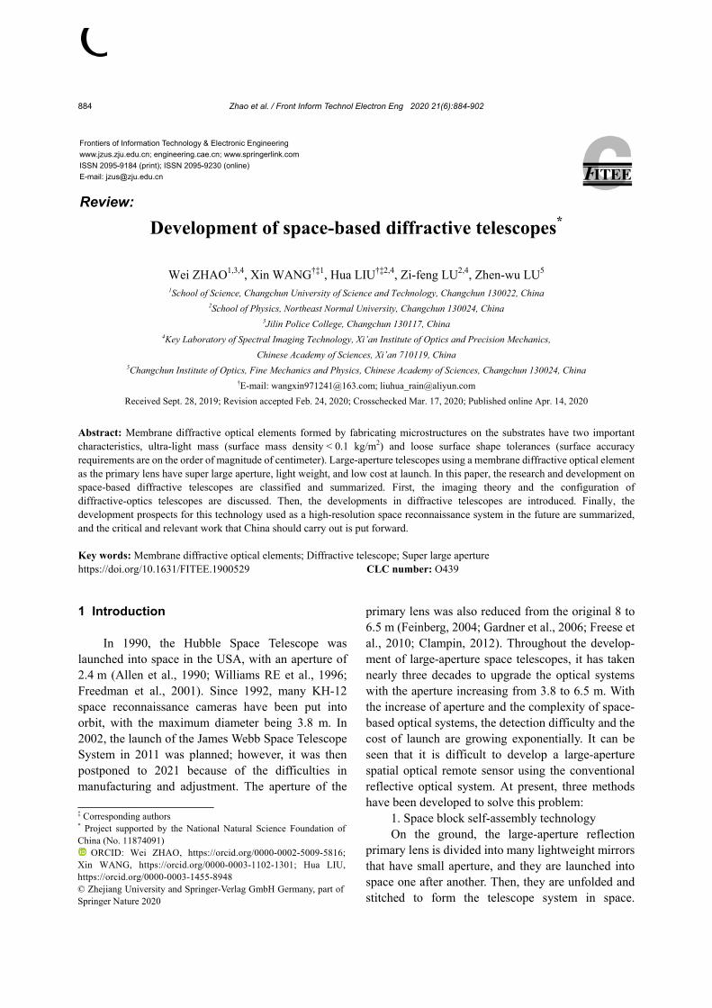
difference according to their dispersion characteris-tics, the diffractive optical elements are usually etched on the surface of a conventional lens to form a diffractive/refractive hybrid optical system, which can reduce the size and weight of the system so that it is miniature, lightweight, and highly integrated. Of course, a true diffractive ultra-thin membrane lens can be developed based on the wavefront modulation characteristics of binary optics. These lenses have many advantages such as being ultra-thin, flat, and foldable, with large aperture over traditional optical components (lenses and mirrors). These diffractive ultra-thin membrane lenses are used in super-large- aperture diffractive telescope systems deployed in geostationary orbit, lightweight optical payloads for small satellites, and long-range and high-intensity laser transmitting and receiving systems in space. The diffractive membrane lens is a continuous or multi- step relief structure with 2π mode etched on the sub-strate (Fig. 1). It can be made into a series of relief structures with a surface depth of about 1 μm in the visible light band. With a flat substrate more than 10 μm thick, the entire diffractive lens can be very thin and easy to fold. By adjusting the parameters of the phase step such as the position, width, depth, and shape structure, the binary optical element generates not only a wavefront of arbitrary shape, but also dis-persion and temperature characteristics that are the opposite of conventional optical lenses. The diffrac-tion efficiency of the binary optical element is related to the number of phase steps of the relief structure. The larger the number of steps is, the higher the dif-fraction efficiency is. When the number of steps reaches 16 and even more, the phase forms a con-tinuous phase structure, and the diffraction efficiency almost reaches 100%.
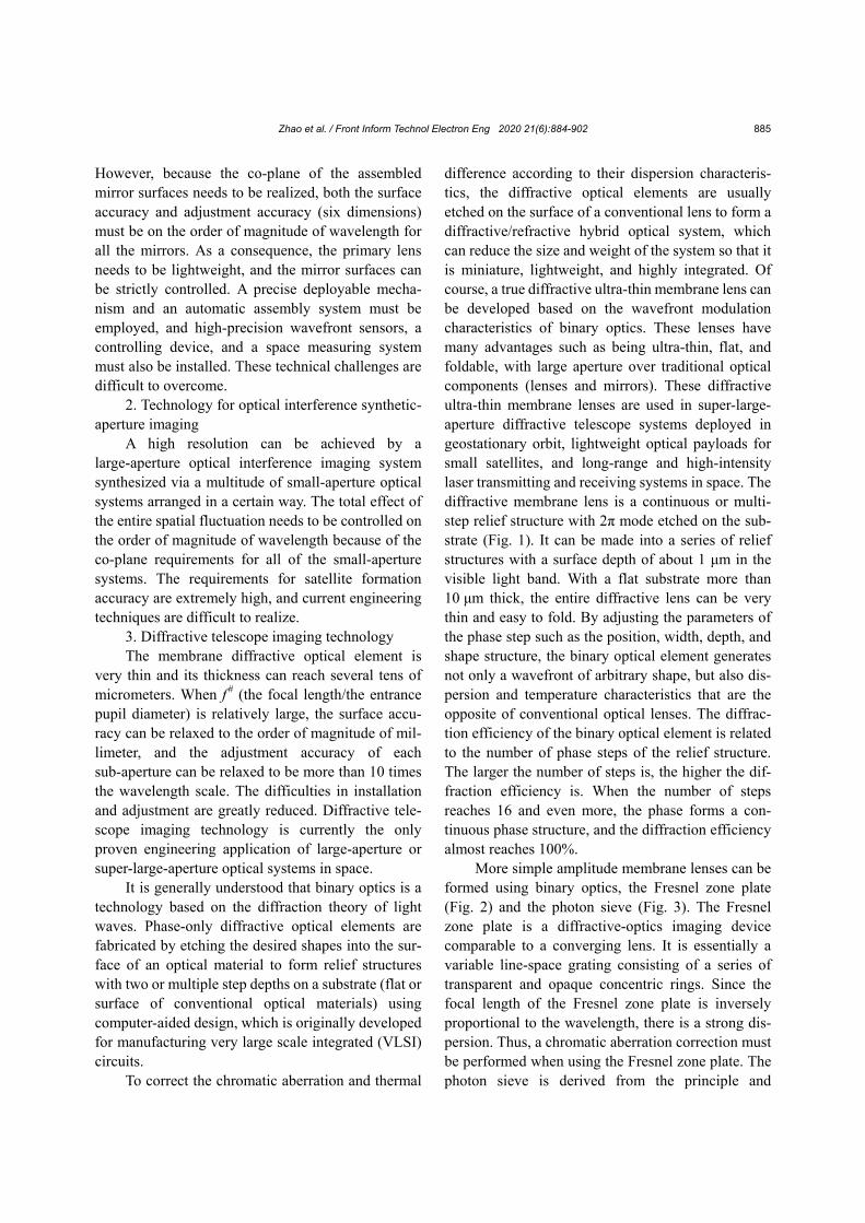
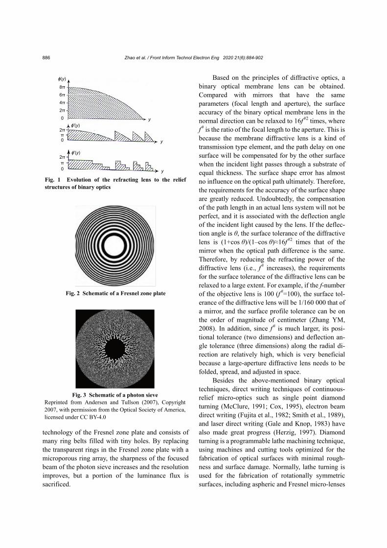
More simple amplitude membrane lenses can be formed using binary optics, the Fresnel zone plate (Fig. 2) and the photon sieve (Fig. 3). The Fresnel zone plate is a diffractive-optics imaging device comparable to a converging lens. It is essentially a variable line-space grating consisting of a series of transparent and opaque concentric rings. Since the focal length of the Fresnel zone plate is inversely proportional to the wavelength, there is a strong dis-persion. Thus, a chromatic aberration correction must be performed when using the Fresnel zone plate. The photon sieve is derived from the principle and
Zhao et al. / Front Inform Technol Electron Eng 2020 21(6):884-902 886
technology of the Fresnel zone plate and consists of many ring belts filled with tiny holes. By replacing the transparent rings in the Fresnel zone plate with a microporous ring array, the sharpness of the focused beam of the photon sieve increases and the resolution improves, but a portion of the luminance flux is sacrificed.
Based on the principles of diffractive optics, a binary optical membrane lens can be obtained. Compared with mirrors that have the same parameters (focal length and aperture), the surface accuracy of the binary optical membrane lens in the normal direction can be relaxed to 16f
#2 times, where f
# is the ratio of the focal length to the aperture. This is because the membrane diffractive lens is a kind of transmission type element, and the path delay on one surface will be compensated for by the other surface when the incident light passes through a substrate of equal thickness. The surface shape error has almost no influence on the optical path ultimately. Therefore, the requirements for the accuracy of the surface shape are greatly reduced. Undoubtedly, the compensation of the path length in an actual lens system will not be perfect, and it is associated with the deflection angle of the incident light caused by the lens. If the deflec-tion angle is θ, the surface tolerance of the diffractive lens is (1+cos θ)/(1‒cos θ)≈16f
#2 times that of the mirror when the optical path difference is the same. Therefore, by reducing the refracting power of the diffractive lens (i.e., f
# increases), the requirements for the surface tolerance of the diffractive lens can be relaxed to a large extent. For example, if the f-number of the objective lens is 100 (f
#=100), the surface tol-erance of the diffractive lens will be 1/160 000 that of a mirror, and the surface profile tolerance can be on the order of magnitude of centimeter (Zhang YM, 2008). In addition, since f
# is much larger, its posi-tional tolerance (two dimensions) and deflection an-gle tolerance (three dimensions) along the radial di-rection are relatively high, which is very beneficial because a large-aperture diffractive lens needs to be folded, spread, and adjusted in space.
Besides the above-mentioned binary optical techniques, direct writing techniques of continuous- relief micro-optics such as single point diamond turning (McClure, 1991; Cox, 1995), electron beam direct writing (Fujita et al., 1982; Smith et al., 1989), and laser direct writing (Gale and Knop, 1983) have also made great progress (Herzig, 1997). Diamond turning is a programmable lathe machining technique, using machines and cutting tools optimized for the fabrication of optical surfaces with minimal rough-ness and surface damage. Normally, lathe turning is used for the fabrication of rotationally symmetric surfaces, including aspheric and Fresnel micro-lenses
8π
6π
4π
2π
0
ϕ(y)
y
y
y
ϕ′(y)
ϕ′(y)
2ππ0
2ππ0
Fig. 1 Evolution of the refracting lens to the relief structures of binary optics
Fig. 2 Schematic of a Fresnel zone plate
Fig. 3 Schematic of a photon sieve Reprinted from Andersen and Tullson (2007), Copyright 2007, with permission from the Optical Society of America, licensed under CC BY-4.0
Zhao et al. / Front Inform Technol Electron Eng 2020 21(6):884-902 887
and other types of kinoforms. The surface roughness of the optical surfaces produced by this technique is generally less than 10 nm. The machining precision depends mainly on the diamond cutting head and the lathe, and the lather is required to have higher preci-sion. The materials limit the applications of diamond turning, and the fabrication sizes of the microstruc-tures should not be too small. Laser direct writing is a kind of maskless photolithography. It was originally used to manufacture metal dies for electronic com-ponents (Piqué et al., 1999). Using a laser beam with variable intensity to control the exposure to the pho-toresist materials on the substrate surface, one achieves the desired microstructure in the photoresist layer after development. Compared with electron beam direct writing, laser direct writing does not require exposure under vacuum. Therefore, laser direct writing has the advantages of low cost and no special operating environment requirements. In recent years, owing to ultra-short pulse duration and ultra-high instantaneous peak power, the femtosecond laser has been widely used for high precision processing (Chichkov et al., 1996; Kawata et al., 2001; Yu et al., 2020). Femtosecond laser direct writing is a mul-tiphoton absorption process, also known as “mul-tiphoton lithography,” which can realize machining accuracy beyond the diffraction limit and complicated microstructures with minimal additional thermal damage. Compared with traditional lithography, it has the advantages of low environmental requirements, wide material applicability, true three-dimensional processing, flexible design, and better controllability. The direct writing technique greatly enriches the preparation of micro-optical diffractive optical elements.
Compared with other space telescope technolo-gies, the diffraction telescopic technology is currently the only engineering application method for large aperture and even super-large-aperture optical sys-tems that can be realized in space. It is also a hot topic of research at home and abroad (Buralli and Morris, 1992; Andersen and Tullson, 2007; Andersen, 2010; Hinglais, 2011; Sanders, 2013; Asmolova et al., 2014). Diffractive-optics imaging technology has great po-tential in satellite applications and it can make low- and high-Earth-orbit imaging satellites miniaturized and well differentiated, respectively. The former strives to simplify the structures of the imaging
system and satellite without reducing the imaging capability of the camera, so as to reduce the cost and engineering difficulty required for large-scale net-working; the latter seeks to significantly improve the performance of imaging satellites without increasing the size of the satellite, and to realize the ability to continuously monitor a wide area via a few satellites. In view of this application potential, the USA has been committed to research in the related technolo-gies since 1995. Over the last 20 years or more, diffraction-based imaging technology has evolved to become one of the most promising technologies, as a space-based Earth surveillance system. It is the only technology in this area that is still making progress.
In this paper, the basic principles and structures of diffractive optics-based telescope systems are in-troduced in detail, and the status of the current re-search and progress is systematically discussed. The technical development trends for the diffractive optics-based telescope system as a large aperture space-based reconnaissance system are summarized. The relevant techniques requiring a focus on further development and breakthroughs are proposed.
2 Principles and structure of the diffractive telescope system
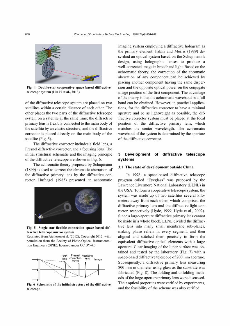
Using a large-diameter diffractive element as the primary lens, the weight of the space telescope system can be reduced due to the thin layer, folding ability, and the surface tolerance of the diffractive optical element. However, due to the high dispersion and stray light of the diffractive element, the chromatic aberration needs to be corrected by the subsequent optical system to widen the working wavelength band, and part of the stray light must be excluded by taking certain measures. Based on the above, a diffractive corrector needs to be introduced into the optical sys-tem. Thus, a large-aperture space telescope system employing a diffractive optical element is composed of a diffractive primary lens and a diffractive correc-tor. The diffractive primary lens is responsible for collecting the optical information, and the diffractive corrector is used to correct the optical aberration. There are two forms of future space-based diffractive telescope systems. One is a cooperative-type space diffractive imaging camera (Fig. 4), where two parts
Zhao et al. / Front Inform Technol Electron Eng 2020 21(6):884-902 888
of the diffractive telescope system are placed on two satellites within a certain distance of each other. The other places the two parts of the diffractive telescope system on a satellite at the same time; the diffractive primary lens is flexibly connected to the main body of the satellite by an elastic structure, and the diffractive corrector is placed directly on the main body of the satellite (Fig. 5).
The diffractive corrector includes a field lens, a Fresnel diffractive corrector, and a focusing lens. The initial structural schematic and the imaging principle of the diffractive telescope are shown in Fig. 6.
The achromatic theory proposed by Schupmann (1899) is used to correct the chromatic aberration of the diffractive primary lens by the diffractive cor-rector. Hufnagel (1985) presented an achromatic
imaging system employing a diffractive hologram as the primary element. Faklis and Morris (1989) de-scribed an optical system based on the Schupmann’s design, using holographic lenses to produce a well-corrected image in broadband light. Based on the achromatic theory, the correction of the chromatic aberration of any component can be achieved by placing another component having the same disper-sion and the opposite optical power on the conjugate image position of the first component. The advantage of the theory is that the achromatic waveband in a full band can be obtained. However, in practical applica-tions, for the diffractive corrector to have a minimal aperture and be as lightweight as possible, the dif-fractive corrector system must be placed at the focal position of the diffractive primary lens, which matches the center wavelength. The achromatic waveband of the system is determined by the aperture of the diffractive corrector.
3 Development of diffractive telescope systems
3.1 The state of development outside China
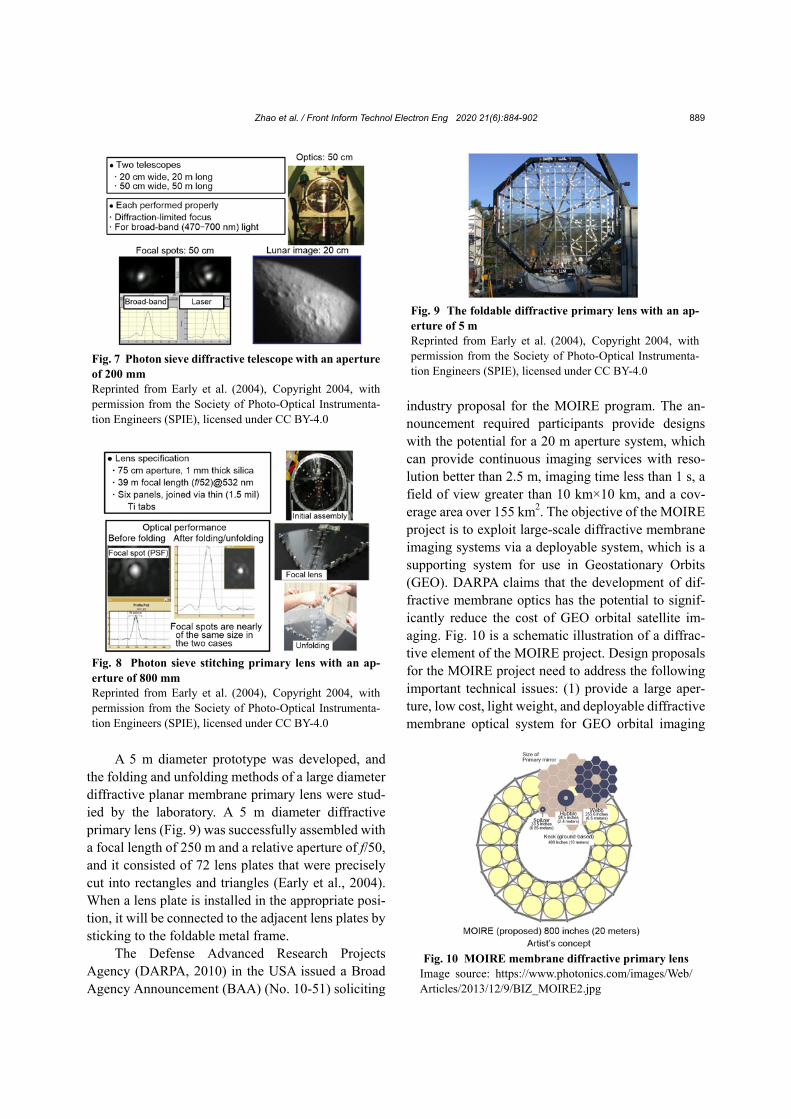
In 1998, a space-based diffractive telescope program called “Eyeglass” was proposed by the Lawrence Livermore National Laboratory (LLNL) in the USA. To form a cooperative telescope system, the system was made up of two satellites several kilo-meters away from each other, which comprised the diffractive primary lens and the diffractive light cor-rector, respectively (Hyde, 1999; Hyde et al., 2002). Since a large-aperture diffractive primary lens cannot be made in a whole block, LLNL divided the diffrac-tive lens into many small membrane sub-planes, making phase reliefs in every segment, and then aligned and stitched them precisely to form the equivalent diffractive optical elements with a large aperture. Clear imaging of the lunar surface was ob-tained and tested by the laboratory (Fig. 7) with a space-based diffractive telescope of 200 mm aperture. Subsequently, a diffractive primary lens measuring 800 mm in diameter using glass as the substrate was fabricated (Fig. 8). The folding and unfolding meth-ods of the large-aperture primary lens were discussed. Their optical properties were verified by experiments, and the feasibility of the scheme was also verified.
Fig. 4 Double-star cooperative space based diffractive telescope system (Liu H et al., 2013)
Fig. 6 Schematic of the initial structure of the diffractive telescope
Fig. 5 Single-star flexible connection space based dif-fractive telescope mirror system Reprinted from Atcheson et al. (2012), Copyright 2012, with permission from the Society of Photo-Optical Instrumenta-tion Engineers (SPIE), licensed under CC BY-4.0
Zhao et al. / Front Inform Technol Electron Eng 2020 21(6):884-902 889
A 5 m diameter prototype was developed, and the folding and unfolding methods of a large diameter diffractive planar membrane primary lens were stud-ied by the laboratory. A 5 m diameter diffractive primary lens (Fig. 9) was successfully assembled with a focal length of 250 m and a relative aperture of f/50, and it consisted of 72 lens plates that were precisely cut into rectangles and triangles (Early et al., 2004). When a lens plate is installed in the appropriate posi-tion, it will be connected to the adjacent lens plates by sticking to the foldable metal frame.
The Defense Advanced Research Projects Agency (DARPA, 2010) in the USA issued a Broad Agency Announcement (BAA) (No. 10-51) soliciting
industry proposal for the MOIRE program. The an-nouncement required participants provide designs with the potential for a 20 m aperture system, which can provide continuous imaging services with reso-lution better than 2.5 m, imaging time less than 1 s, a field of view greater than 10 km×10 km, and a cov-erage area over 155 km2. The objective of the MOIRE project is to exploit large-scale diffractive membrane imaging systems via a deployable system, which is a supporting system for use in Geostationary Orbits (GEO). DARPA claims that the development of dif-fractive membrane optics has the potential to signif-icantly reduce the cost of GEO orbital satellite im-aging. Fig. 10 is a schematic illustration of a diffrac-tive element of the MOIRE project. Design proposals for the MOIRE project need to address the following important technical issues: (1) provide a large aper-ture, low cost, light weight, and deployable diffractive membrane optical system for GEO orbital imaging
Fig. 7 Photon sieve diffractive telescope with an aperture of 200 mm Reprinted from Early et al. (2004), Copyright 2004, with permission from the Society of Photo-Optical Instrumenta-tion Engineers (SPIE), licensed under CC BY-4.0
Fig. 8 Photon sieve stitching primary lens with an ap-erture of 800 mm Reprinted from Early et al. (2004), Copyright 2004, with permission from the Society of Photo-Optical Instrumenta-tion Engineers (SPIE), licensed under CC BY-4.0
Fig. 9 The foldable diffractive primary lens with an ap-erture of 5 m Reprinted from Early et al. (2004), Copyright 2004, with permission from the Society of Photo-Optical Instrumenta-tion Engineers (SPIE), licensed under CC BY-4.0
Fig. 10 MOIRE membrane diffractive primary lensImage source: https://www.photonics.com/images/Web/ Articles/2013/12/9/BIZ_MOIRE2.jpg
Zhao et al. / Front Inform Technol Electron Eng 2020 21(6):884-902 890
systems; (2) possess near real-time imaging stability and high precision in image localization; (3) make the spectrum of the imaging system wider; (4) solve the stability and dynamics problems of large-scale structures in GEO orbits.
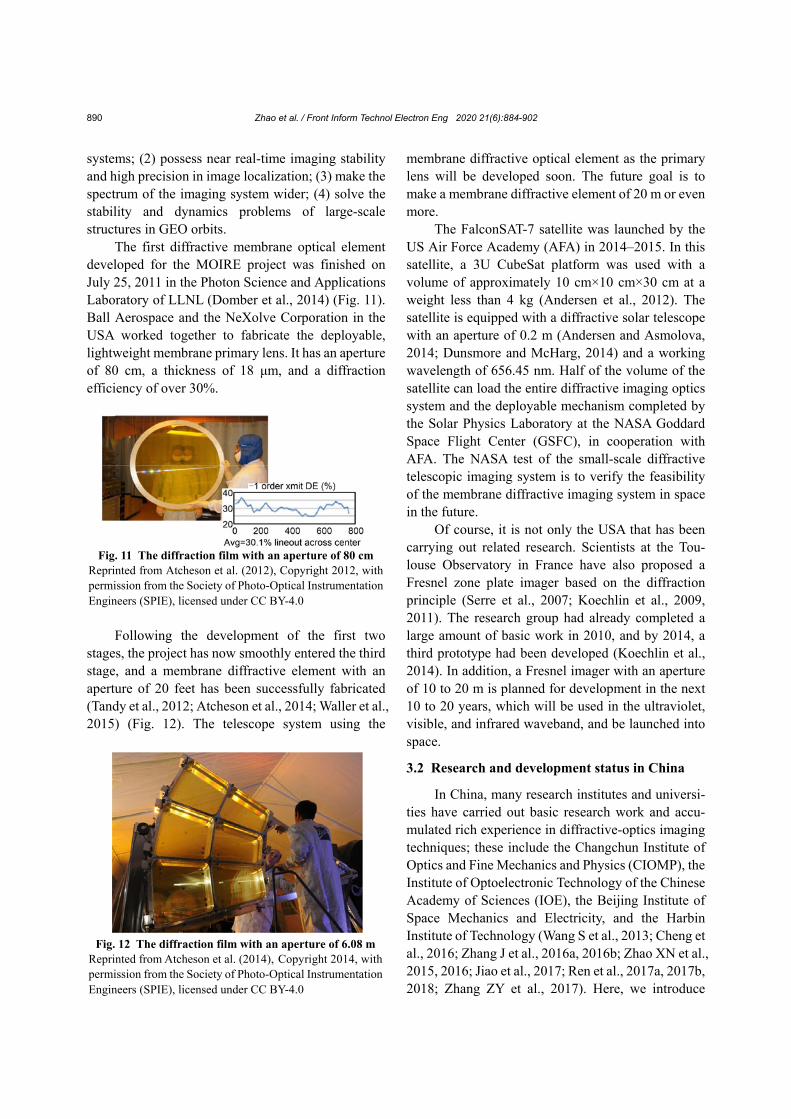
The first diffractive membrane optical element developed for the MOIRE project was finished on July 25, 2011 in the Photon Science and Applications Laboratory of LLNL (Domber et al., 2014) (Fig. 11). Ball Aerospace and the NeXolve Corporation in the USA worked together to fabricate the deployable, lightweight membrane primary lens. It has an aperture of 80 cm, a thickness of 18 μm, and a diffraction efficiency of over 30%.
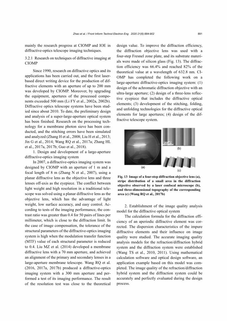
Following the development of the first two
stages, the project has now smoothly entered the third stage, and a membrane diffractive element with an aperture of 20 feet has been successfully fabricated (Tandy et al., 2012; Atcheson et al., 2014; Waller et al., 2015) (Fig. 12). The telescope system using the
membrane diffractive optical element as the primary lens will be developed soon. The future goal is to make a membrane diffractive element of 20 m or even more.
The FalconSAT-7 satellite was launched by the US Air Force Academy (AFA) in 2014–2015. In this satellite, a 3U CubeSat platform was used with a volume of approximately 10 cm×10 cm×30 cm at a weight less than 4 kg (Andersen et al., 2012). The satellite is equipped with a diffractive solar telescope with an aperture of 0.2 m (Andersen and Asmolova, 2014; Dunsmore and McHarg, 2014) and a working wavelength of 656.45 nm. Half of the volume of the satellite can load the entire diffractive imaging optics system and the deployable mechanism completed by the Solar Physics Laboratory at the NASA Goddard Space Flight Center (GSFC), in cooperation with AFA. The NASA test of the small-scale diffractive telescopic imaging system is to verify the feasibility of the membrane diffractive imaging system in space in the future.
Of course, it is not only the USA that has been carrying out related research. Scientists at the Tou-louse Observatory in France have also proposed a Fresnel zone plate imager based on the diffraction principle (Serre et al., 2007; Koechlin et al., 2009, 2011). The research group had already completed a large amount of basic work in 2010, and by 2014, a third prototype had been developed (Koechlin et al., 2014). In addition, a Fresnel imager with an aperture of 10 to 20 m is planned for development in the next 10 to 20 years, which will be used in the ultraviolet, visible, and infrared waveband, and be launched into space.
3.2 Research and development status in China
In China, many research institutes and universi-ties have carried out basic research work and accu-mulated rich experience in diffractive-optics imaging techniques; these include the Changchun Institute of Optics and Fine Mechanics and Physics (CIOMP), the Institute of Optoelectronic Technology of the Chinese Academy of Sciences (IOE), the Beijing Institute of Space Mechanics and Electricity, and the Harbin Institute of Technology (Wang S et al., 2013; Cheng et al., 2016; Zhang J et al., 2016a, 2016b; Zhao XN et al., 2015, 2016; Jiao et al., 2017; Ren et al., 2017a, 2017b, 2018; Zhang ZY et al., 2017). Here, we introduce
Fig. 11 The diffraction film with an aperture of 80 cm Reprinted from Atcheson et al. (2012), Copyright 2012, with permission from the Society of Photo-Optical Instrumentation Engineers (SPIE), licensed under CC BY-4.0
Fig. 12 The diffraction film with an aperture of 6.08 m Reprinted from Atcheson et al. (2014), Copyright 2014, with permission from the Society of Photo-Optical Instrumentation Engineers (SPIE), licensed under CC BY-4.0
Zhao et al. / Front Inform Technol Electron Eng 2020 21(6):884-902 891
mainly the research progress at CIOMP and IOE in diffractive-optics telescope imaging techniques.
3.2.1 Research on techniques of diffractive imaging at CIOMP
Since 1990, research on diffractive optics and its applications has been carried out, and the first laser- based direct writing device for the production of dif-fractive elements with an aperture of up to 200 mm was developed by CIOMP. Moreover, by upgrading the equipment, apertures of the processed compo-nents exceeded 500 mm (Li FY et al., 2002a, 2002b). Diffractive optics telescope systems have been stud-ied since about 2010. To date, the preliminary design and analysis of a super-large-aperture optical system has been finished. Research on the processing tech-nology for a membrane photon sieve has been con-ducted, and the stitching errors have been simulated and analyzed (Zhang H et al., 2008; Liu H et al., 2013; Jin G et al., 2014; Wang RQ et al., 2017a; Zhang HL et al., 2017a, 2017b; Guo et al., 2018).
1. Design and development of a large-aperture diffractive-optics imaging system
In 2007, a diffractive-optics imaging system was designed by CIOMP with an aperture of 1 m and a focal length of 8 m (Zhang N et al., 2007), using a planar diffractive lens as the objective lens and three lenses off-axis as the eyepiece. The conflict between light weight and high resolution in a traditional tele-scope was solved using a planar diffractive lens as the objective lens, which has the advantage of light weight, low surface accuracy, and easy control. Ac-cording to tests of the imaging performance, the con-trast ratio was greater than 0.4 for 50 pairs of lines per millimeter, which is close to the diffraction limit. In the case of image compensation, the tolerance of the structural parameters of the diffractive-optics imaging system is high when the modulation transfer function (MTF) value of each structural parameter is reduced to 0.4. Liu MZ et al. (2014) developed a membrane diffractive lens with a 70 mm aperture, and achieved an alignment of the primary and secondary lenses in a large-aperture membrane telescope. Wang RQ et al. (2016, 2017a, 2017b) produced a diffractive-optics imaging system with a 300 mm aperture and per-formed a test of its imaging performance. The result of the resolution test was close to the theoretical
design value. To improve the diffraction efficiency, the diffraction objective lens was used with a four-step Fresnel zone plate, and its substrate materi-als were made of silicon glass (Fig. 13). The diffrac-tion efficiency was 66.4% and reached 82% of the theoretical value at a wavelength of 632.8 nm. CI-OMP has completed the following work on a large-aperture diffractive-optics imaging system: (1) design of the achromatic diffraction objective with an ultra-large aperture; (2) design of a three-lens reflec-tive eyepiece that includes the diffractive optical elements; (3) development of the stitching, folding, and unfolding technologies for the diffractive optical elements for large apertures; (4) design of the dif-fractive telescope system.
2. Establishment of the image quality analysis
model for the diffractive optical system The calculation formula for the diffraction effi-
ciency of an aperiodic diffractive element was cor-rected. The dispersion characteristics of the impure diffractive elements and their influence on image quality were studied. The accurate imaging quality analysis models for the refraction/diffraction hybrid system and the diffraction system were established (Wang TS et al., 2010, 2011). Using mathematical calculation software and optical design software, an application example based on this model was com-pleted. The image quality of the refraction/diffraction hybrid system and the diffraction system could be accurately and perfectly evaluated during the design process.
Fig. 13 Image of a four-step diffraction objective lens (a), stripe distribution of a small area in the diffraction objective observed by a laser confocal microscope (b), and three-dimensional topography of the corresponding area (c) (Wang RQ et al., 2017b)
Zhao et al. / Front Inform Technol Electron Eng 2020 21(6):884-902 892
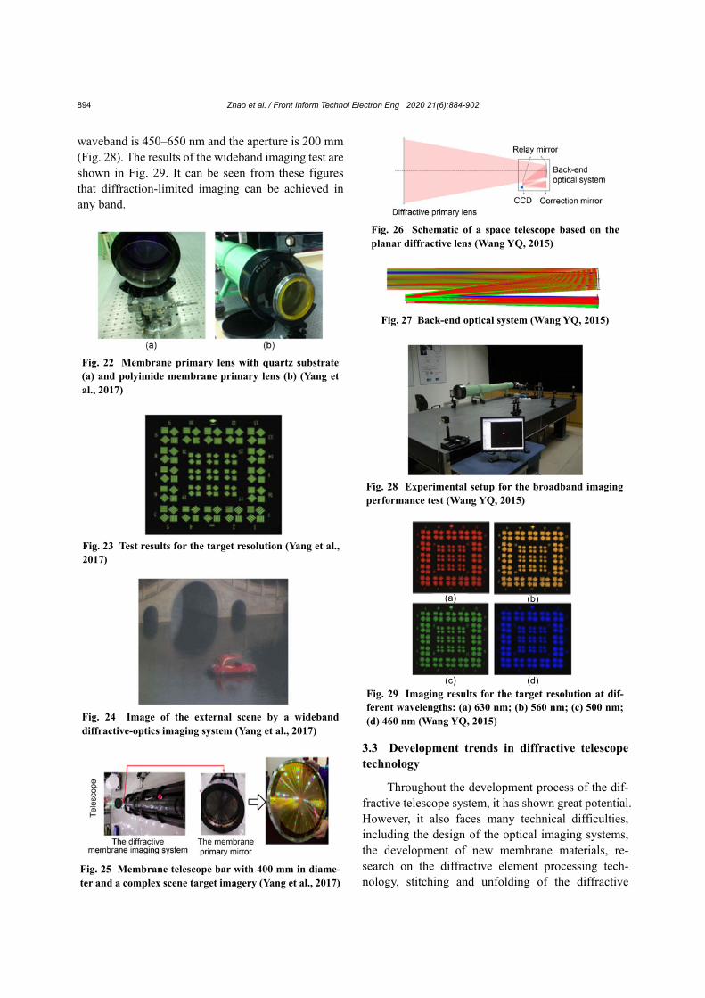
3. Verification and development of the principles for the diffractive compound eye imaging system
Since 2006, a compound eye imaging system has been studied, and its optical model was established at CIOMP (Lu ZW et al., 2006). In 2008, a compound eye diffractive-optics system along with the entire camera structure was designed to solve the problems related to the small field of view and narrow available bandwidth in a diffractive telescope. The field of view can be expanded to 4.2° by the multiple sub-eyepieces arranged in the biologically inspired compound eye, and the simulation results were ideal (Liu H et al., 2008; Yue et al., 2009, 2010).
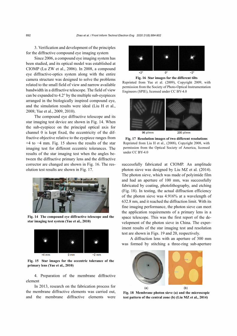
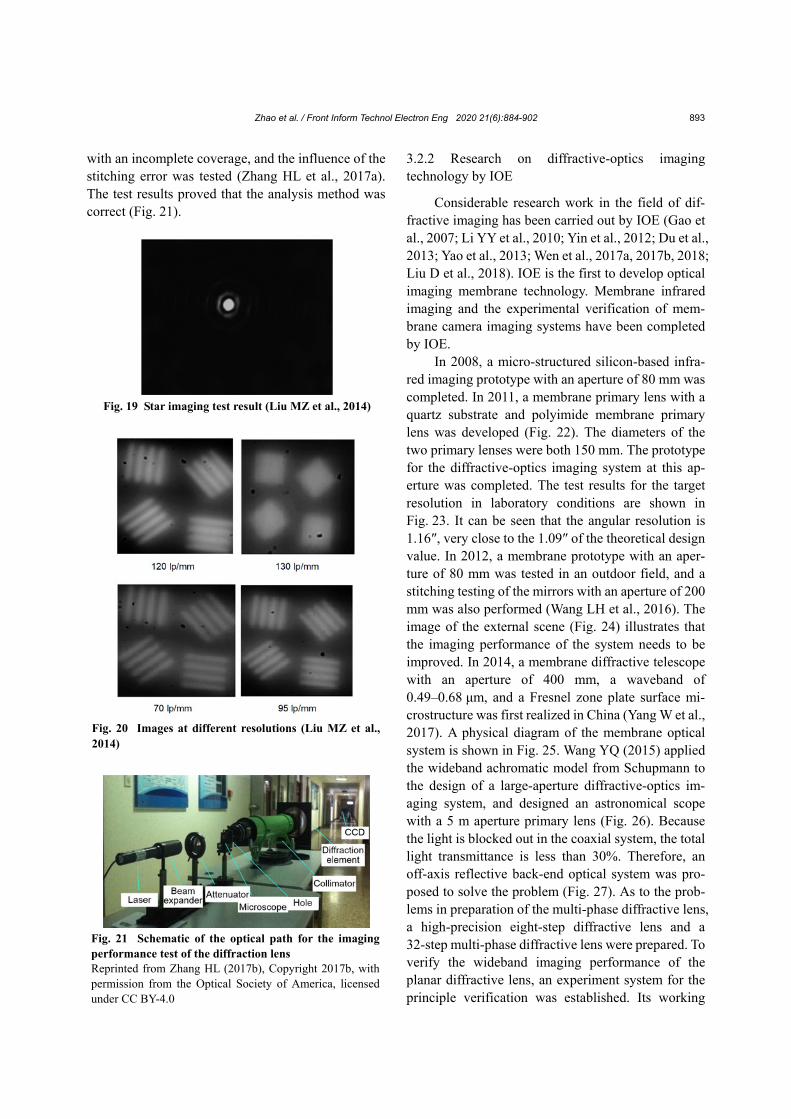
The compound eye diffractive telescope and its star imaging test device are shown in Fig. 14. When the sub-eyepiece on the principal optical axis for channel 0 is kept fixed, the eccentricity of the dif-fractive objective relative to the eyepiece ranges from +4 to −4 mm. Fig. 15 shows the results of the star imaging test for different eccentric tolerances. The results of the star imaging test when the angles be-tween the diffractive primary lens and the diffractive corrector are changed are shown in Fig. 16. The res-olution test results are shown in Fig. 17.
4. Preparation of the membrane diffractive
element In 2013, research on the fabrication process for
the membrane diffractive elements was carried out, and the membrane diffractive elements were
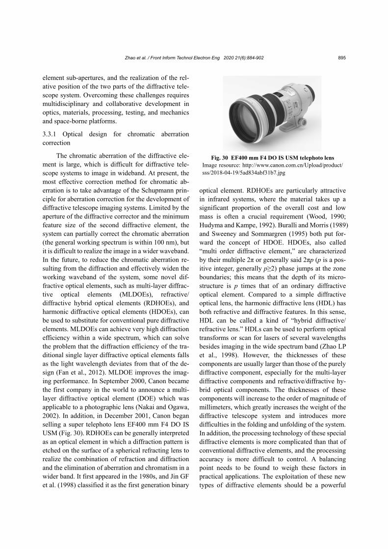
successfully fabricated at CIOMP. An amplitude photon sieve was designed by Liu MZ et al. (2014). The photon sieve, which was made of polyimide film and had an aperture of 100 mm, was successfully fabricated by coating, photolithography, and etching (Fig. 18). In testing, the actual diffraction efficiency of the photon sieve was 4.916% at a wavelength of 632.8 nm, and it reached the diffraction limit. With its fine imaging performance, the photon sieve can meet the application requirements of a primary lens in a space telescope. This was the first report of the de-velopment of the photon sieve in China. The exper-iment results of the star imaging test and resolution test are shown in Figs. 19 and 20, respectively.
A diffraction lens with an aperture of 300 mm was formed by stitching a three-ring sub-aperture
Fig. 14 The compound eye diffractive telescope and the star imaging test system (Yue et al., 2010)
Fig. 15 Star images for the eccentric tolerance of the primary lens (Yue et al., 2010)
Fig. 17 Resolution images of two different resolutions Reprinted from Liu H et al., (2008), Copyright 2008, with permission from the Optical Society of America, licensed under CC BY-4.0
Fig. 18 Membrane photon sieve (a) and the microscopic test pattern of the central zone (b) (Liu MZ et al., 2014)
Fig. 16 Star images for the different tilts Reprinted from Yue et al. (2009), Copyright 2009, with permission from the Society of Photo-Optical Instrumentation Engineers (SPIE), licensed under CC BY-4.0
Zhao et al. / Front Inform Technol Electron Eng 2020 21(6):884-902 893
with an incomplete coverage, and the influence of the stitching error was tested (Zhang HL et al., 2017a). The test results proved that the analysis method was correct (Fig. 21).
3.2.2 Research on diffractive-optics imaging technology by IOE
Considerable research work in the field of dif-fractive imaging has been carried out by IOE (Gao et al., 2007; Li YY et al., 2010; Yin et al., 2012; Du et al., 2013; Yao et al., 2013; Wen et al., 2017a, 2017b, 2018; Liu D et al., 2018). IOE is the first to develop optical imaging membrane technology. Membrane infrared imaging and the experimental verification of mem-brane camera imaging systems have been completed by IOE.
In 2008, a micro-structured silicon-based infra-red imaging prototype with an aperture of 80 mm was completed. In 2011, a membrane primary lens with a quartz substrate and polyimide membrane primary lens was developed (Fig. 22). The diameters of the two primary lenses were both 150 mm. The prototype for the diffractive-optics imaging system at this ap-erture was completed. The test results for the target resolution in laboratory conditions are shown in Fig. 23. It can be seen that the angular resolution is 1.16″, very close to the 1.09″ of the theoretical design value. In 2012, a membrane prototype with an aper-ture of 80 mm was tested in an outdoor field, and a stitching testing of the mirrors with an aperture of 200 mm was also performed (Wang LH et al., 2016). The image of the external scene (Fig. 24) illustrates that the imaging performance of the system needs to be improved. In 2014, a membrane diffractive telescope with an aperture of 400 mm, a waveband of 0.49–0.68 μm, and a Fresnel zone plate surface mi-crostructure was first realized in China (Yang W et al., 2017). A physical diagram of the membrane optical system is shown in Fig. 25. Wang YQ (2015) applied the wideband achromatic model from Schupmann to the design of a large-aperture diffractive-optics im-aging system, and designed an astronomical scope with a 5 m aperture primary lens (Fig. 26). Because the light is blocked out in the coaxial system, the total light transmittance is less than 30%. Therefore, an off-axis reflective back-end optical system was pro-posed to solve the problem (Fig. 27). As to the prob-lems in preparation of the multi-phase diffractive lens, a high-precision eight-step diffractive lens and a 32-step multi-phase diffractive lens were prepared. To verify the wideband imaging performance of the planar diffractive lens, an experiment system for the principle verification was established. Its working
Fig. 19 Star imaging test result (Liu MZ et al., 2014)
Fig. 20 Images at different resolutions (Liu MZ et al., 2014)
Fig. 21 Schematic of the optical path for the imaging performance test of the diffraction lens Reprinted from Zhang HL (2017b), Copyright 2017b, with permission from the Optical Society of America, licensed under CC BY-4.0
Zhao et al. / Front Inform Technol Electron Eng 2020 21(6):884-902 894
waveband is 450–650 nm and the aperture is 200 mm (Fig. 28). The results of the wideband imaging test are shown in Fig. 29. It can be seen from these figures that diffraction-limited imaging can be achieved in any band.
3.3 Development trends in diffractive telescope technology
Throughout the development process of the dif-fractive telescope system, it has shown great potential. However, it also faces many technical difficulties, including the design of the optical imaging systems, the development of new membrane materials, re-search on the diffractive element processing tech-nology, stitching and unfolding of the diffractive
Fig. 24 Image of the external scene by a wideband diffractive-optics imaging system (Yang et al., 2017)
Fig. 22 Membrane primary lens with quartz substrate (a) and polyimide membrane primary lens (b) (Yang et al., 2017)
Fig. 23 Test results for the target resolution (Yang et al., 2017)
Fig. 27 Back-end optical system (Wang YQ, 2015)
Fig. 28 Experimental setup for the broadband imaging performance test (Wang YQ, 2015)
(a) (b)
(c) (d)
Fig. 29 Imaging results for the target resolution at dif-ferent wavelengths: (a) 630 nm; (b) 560 nm; (c) 500 nm; (d) 460 nm (Wang YQ, 2015)
Fig. 25 Membrane telescope bar with 400 mm in diame-ter and a complex scene target imagery (Yang et al., 2017)
Fig. 26 Schematic of a space telescope based on the planar diffractive lens (Wang YQ, 2015)
Zhao et al. / Front Inform Technol Electron Eng 2020 21(6):884-902 895
element sub-apertures, and the realization of the rel-ative position of the two parts of the diffractive tele-scope system. Overcoming these challenges requires multidisciplinary and collaborative development in optics, materials, processing, testing, and mechanics and space-borne platforms.
3.3.1 Optical design for chromatic aberration correction
The chromatic aberration of the diffractive ele-ment is large, which is difficult for diffractive tele-scope systems to image in wideband. At present, the most effective correction method for chromatic ab-erration is to take advantage of the Schupmann prin-ciple for aberration correction for the development of diffractive telescope imaging systems. Limited by the aperture of the diffractive corrector and the minimum feature size of the second diffractive element, the system can partially correct the chromatic aberration (the general working spectrum is within 100 nm), but it is difficult to realize the image in a wider waveband. In the future, to reduce the chromatic aberration re-sulting from the diffraction and effectively widen the working waveband of the system, some novel dif-fractive optical elements, such as multi-layer diffrac-tive optical elements (MLDOEs), refractive/ diffractive hybrid optical elements (RDHOEs), and harmonic diffractive optical elements (HDOEs), can be used to substitute for conventional pure diffractive elements. MLDOEs can achieve very high diffraction efficiency within a wide spectrum, which can solve the problem that the diffraction efficiency of the tra-ditional single layer diffractive optical elements falls as the light wavelength deviates from that of the de-sign (Fan et al., 2012). MLDOE improves the imag-ing performance. In September 2000, Canon became the first company in the world to announce a multi- layer diffractive optical element (DOE) which was applicable to a photographic lens (Nakai and Ogawa, 2002). In addition, in December 2001, Canon began selling a super telephoto lens EF400 mm F4 DO IS USM (Fig. 30). RDHOEs can be generally interpreted as an optical element in which a diffraction pattern is etched on the surface of a spherical refracting lens to realize the combination of refraction and diffraction and the elimination of aberration and chromatism in a wider band. It first appeared in the 1980s, and Jin GF et al. (1998) classified it as the first generation binary
optical element. RDHOEs are particularly attractive in infrared systems, where the material takes up a significant proportion of the overall cost and low mass is often a crucial requirement (Wood, 1990; Hudyma and Kampe, 1992). Buralli and Morris (1989) and Sweeney and Sommargren (1995) both put for-ward the concept of HDOE. HDOEs, also called “multi order diffractive element,” are characterized by their multiple 2π or generally said 2πp (p is a pos-itive integer, generally p≥2) phase jumps at the zone boundaries; this means that the depth of its micro-structure is p times that of an ordinary diffractive optical element. Compared to a simple diffractive optical lens, the harmonic diffractive lens (HDL) has both refractive and diffractive features. In this sense, HDL can be called a kind of “hybrid diffractive/ refractive lens.” HDLs can be used to perform optical transforms or scan for lasers of several wavelengths besides imaging in the wide spectrum band (Zhao LP et al., 1998). However, the thicknesses of these components are usually larger than those of the purely diffractive component, especially for the multi-layer diffractive components and refractive/diffractive hy-brid optical components. The thicknesses of these components will increase to the order of magnitude of millimeters, which greatly increases the weight of the diffractive telescope system and introduces more difficulties in the folding and unfolding of the system. In addition, the processing technology of these special diffractive elements is more complicated than that of conventional diffractive elements, and the processing accuracy is more difficult to control. A balancing point needs to be found to weigh these factors in practical applications. The exploitation of these new types of diffractive elements should be a powerful
Fig. 30 EF400 mm F4 DO IS USM telephoto lens Image resource: http://www.canon.com.cn/Upload/product/ sss/2018-04-19/5ad834abf31b7.jpg
Zhao et al. / Front Inform Technol Electron Eng 2020 21(6):884-902 896
measure to overcome the chromatic aberration in diffractive telescope systems in the future.
At present, many new diffractive elements are emerging. Among them, the MODE lenses (multi- order diffractive engineered material lenses) under development and the metalenses are very attractive because of their potential optical characteristics. The MODE lenses are used in the Nautilus space telescope program at the University of Arizona, which is aimed to create a space telescope that can survey transiting exo-earths for biosignatures 1000 light years away (Apai et al., 2019). The MODE lenses are very lightweight diffractive-transmissive alternatives to the heavy reflective elements (mirrors) used in ad-vanced ground and space-based telescopes. The op-timized multi-order design of these lenses provides essentially achromatic and diffraction-limited per-formance. The Nautilus Unit Telescope will use an 8.5 m diameter f/1.0 focal ratio MODE lens as the light-collecting element for the exoplanet transit spectroscopy observations, and a smaller, 2.5 m di-ameter, wide field-of-view MODE lens for the pho-tometric exoplanet transit search operations. The Nautilus Array will consist of about 35 such unit telescopes, providing a combined light collecting area equivalent to a single 50 m diameter telescope. The Nautilus Unit telescope, with optics consisting of a number of MODE lenses, has a light-collecting area more than twice that of the James Webb Space Tele-scope. Because MODE lenses have three key ad-vantages over telescope mirrors, i.e., much lower weight per unit area, less sensitivity to misalignments/ deformations, and efficient replicability through op-tical molding processes, they will be less expensive to launch into space.
The metalens is being developed for its super- surface structure, with which a powerful control ca-pability of the light field can be realized for not only monochromatic light, but also the continuous spec-trum. It can also provide a correct delay distribution and arbitrary modulation in wavefronts of different wavelengths (Li K et al., 2017; Qin et al., 2017; Chen et al., 2018; Lv et al., 2019). The metalens can be made into an ultra-thin plane by artificially designing the structures to obtain the extraordinary physical properties that natural materials cannot have. The thin layer is the metasurface that can flexibly regulate the amplitude, phase, and polarization of incident light to
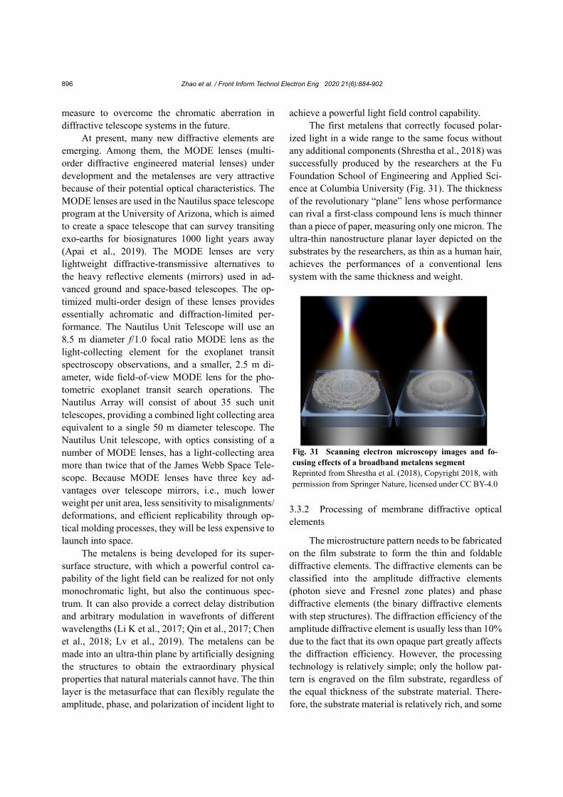
achieve a powerful light field control capability. The first metalens that correctly focused polar-
ized light in a wide range to the same focus without any additional components (Shrestha et al., 2018) was successfully produced by the researchers at the Fu Foundation School of Engineering and Applied Sci-ence at Columbia University (Fig. 31). The thickness of the revolutionary “plane” lens whose performance can rival a first-class compound lens is much thinner than a piece of paper, measuring only one micron. The ultra-thin nanostructure planar layer depicted on the substrates by the researchers, as thin as a human hair, achieves the performances of a conventional lens system with the same thickness and weight.
3.3.2 Processing of membrane diffractive optical elements
The microstructure pattern needs to be fabricated on the film substrate to form the thin and foldable diffractive elements. The diffractive elements can be classified into the amplitude diffractive elements (photon sieve and Fresnel zone plates) and phase diffractive elements (the binary diffractive elements with step structures). The diffraction efficiency of the amplitude diffractive element is usually less than 10% due to the fact that its own opaque part greatly affects the diffraction efficiency. However, the processing technology is relatively simple; only the hollow pat-tern is engraved on the film substrate, regardless of the equal thickness of the substrate material. There-fore, the substrate material is relatively rich, and some
Fig. 31 Scanning electron microscopy images and fo-cusing effects of a broadband metalens segment Reprinted from Shrestha et al. (2018), Copyright 2018, with permission from Springer Nature, licensed under CC BY-4.0
Zhao et al. / Front Inform Technol Electron Eng 2020 21(6):884-902 897
metal or organic films can be used as the substrate. Because the realization of an amplitude diffractive element is relatively easy and the process is simple, it is suitable for countries with slightly smaller research programs in diffractive telescope systems. For ex-ample, Koechlin et al. (2012) used the amplitude diffractive elements as the primary lens in the tele-scope system. As far as the current technologies in China are concerned, it is also suitable to start from the amplitude diffractive element. The phase diffrac-tive optical element has high diffraction efficiency, and even if it has only four steps, the diffraction effi-ciency can also reach more than 40%. If 16 steps can be realized, the diffraction efficiency will be greater than 98%, which means that almost all the incident energy can be used. However, because the total light transmittance of the phase diffractive optical element is almost 100%, the requirement of equal thickness of its substrate material is very high, and it needs to be within λ/10. The substrate material is required to have a small coefficient of thermal expansion, low density, and good ductility and durability. The material is required to not only adapt to the space environment but also withstand all kinds of radiation in space. It is currently recognized that polyimide optical materials are the most suitable. The NeXolve Corporation in the USA used polyimide to fabricate an optical film which has good adaptability in space environments. Its thickness is about 20 μm, and its equal thickness is controlled to be within λ/20. The processing precision of the polyimide film is limited because polyimide materials absorb water and deform. However, touch-ing water is unavoidable during the processing of traditional binary diffractive elements (gluing, ex-posure, development, and etching). A feasible method is to form a template with a step structure on a quartz substrate, and then directly use polyimide film forming technology to imprint the membrane dif-fractive optical element with a step structure. How-ever, the equal thickness control of this technology is very demanding and can be realized only in the USA. The requirements for equal thickness control in China cannot yet be met, and developing expertise and ca-pabilities in this technique is exactly the direction that China needs to pursue. Currently, some research in-stitutes and universities are in the process of devel-oping the related research in this area, including Soochow University.
3.3.3 Stitching and unfolding technology
Single-piece large-aperture diffractive elements will be impossible in the future. A complete and giant diffractive primary lens is made up of many small pieces of sub-apertures, which are put together using a stitching technology. The sub-aperture needs to be opened by a mechanical structure because it is made of films, and its shape may be arbitrary. At present, an ideal shape for the sub-aperture is circularity or sector with smooth edges and corners. Thus, its marginal part will be easily in full contact with the mechanical structure, which will make its sufferance force uni-form, so that the film of the entire sub-aperture can be smoothly unfolded and its wrinkles can be reduced. Moreover, during the stitching process, the positions of these sub-apertures need to be precisely controlled within a certain range to ensure the imaging quality of the diffractive elements. These stitching tolerances include three categories and five dimensions: radial tolerance (both x and y directions), axial tolerance (z direction), and inclination tolerances (both x and y directions). They are all related to the radial position in which they are located and the focal length of the diffractive element. The effect of these stitching tol-erances on the wavefront of the diffractive element can be obtained by means of joint modeling between the mathematical calculation software and optical design software. Conversely, if we have knowledge of the distribution of the diffraction wavefront via an interferometer, the corresponding stitching error will be derived by inversion calculation. In this way, the stitching and adjustment can be conducted, and all the sub-apertures will be in place. When the stitching structure is designed, its folding and unfolding pro-cesses need to be taken into account, and in particular, a certain rigidity needs to be guaranteed, so as to restore the precision of stitching after unfolding.
3.3.4 Realization of the relative spatial position for two parts of the diffractive telescope system
Based on the imaging principle, the diffractive telescope system contains two major parts: the dif-fractive primary lens and the diffractive corrector. The two parts are far away from each other, and need to maintain a certain position as regard to the distance, the relative radial position (both x and y directions), and the inclination angle (both x and y directions).
Zhao et al. / Front Inform Technol Electron Eng 2020 21(6):884-902 898
This requirement means that the relative position has five dimensions. Appropriate methods that can measure and give feedback on this information in real time need to be proposed, because the accuracy re-quirements on the relative positions are very high. Laser measurement methods are very suitable for use; for example, the distance can be measured by laser range finders. By adding some special diffractive optical elements and detectors to the laser distance measuring system, the relative radial position and inclination angle can be precisely measured. In short, many laser testing methods can be applied to measure the relative position between the two parts. In addi-tion, for the diffractive telescope system with an ap-erture of more than 10 m, the two parts are usually mounted on different satellite platforms. For this reason, satellite cooperation and networking tech-nologies are required. Thus, a space-borne platform must be perfected to a greater degree, and its pointing accuracy and stability need to be improved and per-fected, which is key to realizing diffractive telescope systems in the future. For the diffractive telescope system with an aperture of less than 10 m, by com-pressing the focal length of the diffractive element, the distance of the primary lens and the diffractive corrector can be shortened so as to be mounted on the same space-borne platform. The diffractive primary lens will be stretched and opened by the flexible connection system after it is launched into space. The stretching technology requires very good stability to ensure that the position of the stretched diffractive primary lens relative to the diffractive corrector is within a certain accuracy range. The corresponding measurement, adjustment, and compensation mecha-nisms are required.
4 Conclusions Throughout the history of large-aperture space
telescopes, nearly 30 years of development have been needed to increase the aperture of the optical system from 3.8 to 6.5 m. With the increase in aperture, during the development of space optical systems, the testing difficulty and the cost of launching will have an exponential growth. Space-based optical remote sensors with an aperture of 30 m or more will be difficult to achieve given the current technical levels
if a conventional reflective optical system is used. One of the most important factors is the weight. For example, the surface density of the primary lens of the Hubble Space Telescope is 200 kg/m2. The surface mass density of the James Webb primary lens (the next generation of the Hubble Telescope) is expected to be reduced to 15 kg/m2. For the primary lens of a super-large-aperture telescope, the surface mass den-sity must be further reduced in the future. Diffractive optics provides another very attractive method for space telescopes. Fresnel lenses based on the princi-ples of diffractive optics can be fabricated on the surface of the film and such a lens has two important characteristics, ultra-light mass and high tolerances. In the visible waveband, regardless of the support structure, a Fresnel diffractive lens with an aperture of 25 m and a thickness of 10 μm needs only glasses of 10 kg and a surface mass density of about 0.02 kg/m2, thereby reducing the emission load.
From the conceptual design of the original dif-fractive membrane lens from LLNL, to the on-orbit verification of the FalconSAT-7 membrane diffractive telescope from AFA, and to the collimation GEO high-resolution imaging of the diffractive membrane imaging system supported by DARPA at present, it can be seen that the interest and investment in diffractive-optics imaging technology by the USA is constantly improving. If the spatial reliability and performance of the photon sieve are successfully verified by FalconSAT-7, under conditions of main-taining high resolution, the miniaturization and even microminiaturization of a low-orbit satellite will be first realized by diffractive-optics imaging technology. Soon afterwards, the USA will use technologies to develop large-aperture high-orbit imaging satellites, and ultimately achieve high-resolution continuous surveillance based on space-borne detection.
The development of this technology cannot be finished overnight; it needs time to accumulate. Be-sides, the technology involves a wide range of fields, including satellite platforms, new materials, pro-cessing technology, space-based optics, and many other aspects. According to the state of the current research in China, it is necessary to carry out research in the relevant technologies and applications, and verify the work step by step in powerful combinations. The key technologies for super-large-aperture diffractive imaging should be developed as soon as
Zhao et al. / Front Inform Technol Electron Eng 2020 21(6):884-902 899
possible. The new diffractive optical elements need to be developed to extend the working waveband of diffractive telescope systems, and the equal thickness membrane materials need to be developed to form the phase diffraction membrane diffractive elements with high diffraction efficiency. The stitching and testing techniques for the membrane diffractive elements need to be developed to form the large-aperture foldable diffractive elements, and the space deploya-ble techniques need to be developed to form a feasible space deployable scheme. The stability control tech-nology for the satellite needs to be developed to form a stable satellite platform that guarantees optical im-aging quality. In conclusion, if the diffractive tele-scope system is to be realized, there are still many technologies that need to be developed and mastered. The road ahead is very long, but the prospects are very attractive.
Contributors Hua LIU and Zhen-wu LU guided the research. Wei
ZHAO and Xin WANG collected the literature. Wei ZHAO analyzed and summarized the literature. Zi-feng LU drafted the manuscript. Wei ZHAO and Xin WANG helped organize the manuscript. Hua LIU revised and finalized the paper. Compliance with ethics guidelines
Wei ZHAO, Xin WANG, Hua LIU, Zi-feng LU, and Zhen-wu LU declare that they have no conflict of interest.
References Allen L, Angel R, Mangus JD, et al., 1990. The Hubble Space
Telescope Optical Systems Failure Report. NASA-TM- 103 443, NASA (National Aeronautics and Space Ad-ministration), Washington, USA.
Andersen G, 2010. Membrane photon sieve telescopes. Appl Opt, 49(33):6391-6394. https://doi.org/10.1364/AO.49.006391
Andersen G, Asmolova O, 2014. FalconSAT-7: a membrane space telescope. SPIE Astronomical Telescopes + In-strumentation, Article 91431X. https://doi.org/10.1117/12.2054441
Andersen G, Tullson D, 2007. Broadband antihole photon sieve telescope. Appl Opt, 46(18):3706-3708. https://doi.org/10.1364/AO.46.003706
Andersen G, Asmolov O, Dearborn ME, et al., 2012. Fal-conSAT-7: a membrane photon sieve CubeSat solar tel-escope. SPIE Astronomical Telescopes + Instrumentation, Article 84421C. https://doi.org/10.1117/12.924250
Apai D, Milster TD, Kim DW, et al., 2019. A thousand earths: a very large aperture, ultralight space telescope array for atmospheric biosignature surveys.
https://arxiv.org/abs/1906.05079 Asmolova O, Andersen G, Dearborn ME, et al, 2014. Optical
testing of a membrane diffractive optic for space-based solar imaging. SPIE OPTO, Article 90060D. https://doi.org/10.1117/12.2037035
Atcheson P, Stewart C, Domber J, et al., 2012. MOIRE: initial demonstration of a transmissive diffractive membrane optic for large lightweight optical telescopes. SPIE Space Telescopes and Instrumentation, Article 844221. https://doi.org/10.1117/12.925413
Atcheson P, Domber J, Whiteaker K, et al., 2014. MOIRE: ground demonstration of a large aperture diffractive transmissive telescope. SPIE Astronomical Telescopes and Instrumentation, Article 91431W. https://doi.org/10.1117/12.2054104
Buralli DA, Morris GM, 1989. Design of a wide field diffrac-tive landscape lens. Appl Opt, 28(18):3950-3959. https://doi.org/10.1364/AO.28.003950
Buralli DA, Morris GM, 1992. Design of two- and three- element diffractive Keplerian telescopes. Appl Opt, 31(1): 38-43. https://doi.org/10.1364/AO.31.000038
Chen WT , Zhu AY, Sanjeev V, et al., 2018. A broadband achromatic metalens for focusing and imaging in the visible. Nat Nanotechnol, 13(3):220-226. https://doi.org/10.1038/s41565-017-0034-6
Cheng YG, Tong JM, Zhu JP, et al., 2016. Clad photon sieve for generating localized hollow beams. Opt Laser Eng, 77:18-25. https://doi.org/10.1016/j.optlaseng.2015.07.003
Chichkov BN, Momma C, Nolte S, et al., 1996. Femtosecond, picosecond and nanosecond laser ablation of solids. Appl Phys A, 63(2):109-115. https://doi.org/10.1007/BF01567637
Clampin M, 2012. Status of the James Webb Space Telescope observatory. SPIE Astronomical Telescopes and Instru-mentation, Article 84422A. https://doi.org/10.1117/12.926429
Cox JA, 1995. Application of diffractive optics to infrared imagers. SPIE Int Symp on Optical Science, Engineering, and Instrumentation, p.304-312. https://doi.org/10.1117/12.218231
DARPA (Defense Advanced Research Projects Agency), 2010. Membrane Optical Imager for Real-Time Exploitation (MOIRE). https://www.richardcyoung.com/terrorism/membrane- optical-imager-for-real-time-exploitation-moire/ [Accessed on Mar. 17, 2020].
Domber JL, Atcheson PD, Kommers J, 2014. MOIRE: ground test bed results for a large membrane telescope. Space-craft Structures Conf, Article 1510.
Du K, Yin KW, Li H, et al., 2013. Design and analysis of a novel self-deployable baffle. 5th Int Symp on Photoelec-tronic Detection and Imaging, Article 890758. https://doi.org/10.1117/12.2034946
Dunsmore A, McHarg M, 2014. FalconSat-7—a deployable solar telescope. 28th Annual AIAA/USU Conf on Small
Zhao et al. / Front Inform Technol Electron Eng 2020 21(6):884-902 900
Satellites, Article SSC14-III-1. Early JT, Hyde R, Baron RL, 2004. Twenty-meter space tele-
scope based on diffractive Fresnel lens. SPIE’s 48th An-nual Meeting: Optical Science and Technology, Article 5166. https://doi.org/10.1117/12.506232
Faklis D, Morris GM, 1989. Broadband imaging with holo-graphic lenses. Opt Eng, 28(6):286592. https://doi.org/10.1117/12.7977006
Fan CJ, Zhao YH, Ying CF, et al., 2012. Multilayer diffraction element with wide field of view and high diffractive ef-ficiency. Chinese Journal of Lasers, 39(5):232-236 (in Chinese). https://doi.org/10.3788/CJL201239.0516001
Feinberg LD, 2004. James Webb Space Telescope (JWST) Optical Telescope Element (OTE) development status. SPIE Astronomical Telescopes and Instrumentation, p.814-817. https://doi.org/10.1117/12.562564
Freedman WL, Madore BF, Gibson BK, et al., 2001. Final results from the Hubble space telescope key project to measure the Hubble constant. Astrophys J, 553(1):47-72. https://doi.org/10.1086/320638
Freese K, Ilie C, Spolyar D, et al., 2010. Supermassive dark stars: detectable in JWST. Astrophys J, 716(2):1397- 1407. https://doi.org/10.1088/0004-637X/716/2/1397
Fujita T, Nishihara H, Koyama J, 1982. Blazed gratings and Fresnel lenses fabricated by electron-beam lithography. Opt Lett, 7(12):578-580. https://doi.org/10.1364/ol.7.000578
Gale MT, Knop K, 1983. The fabrication of fine lens arrays by laser beam writing. SPIE Int Technical Conf/Europe, p.347-353. https://doi.org/10.1117/12.935397
Gao Z, Ma XJ, Zhou CX, et al., 2007. Off-axis imaging of photon sieve with large aperture. Opto-Electronic Engi-neering, 34(9):25-29 (in Chinese). https://doi.org/10.3969/j.issn.1003-501X.2007.09.006
Gardner JP, Mather JC, Clampin M, et al., 2006. The James Webb Space Telescope. Space Sci Rev, 123(4):485-606. https://doi.org/10.1007/s11214-006-8315-7
Guo CL, Zhang ZY, Xue DL, et al., 2018. High-performance etching of multilevel phase-type Fresnel zone plates with large apertures. Opt Commun, 407:227-233. https://doi.org/10.1016/j.optcom.2017.09.006
Herzig HP, 1997. Micro-Optics: Elements, Systems and Ap-plications. CRC Press, Taylor & Francis Group, London, UK.
Hinglais E, 2011. A space Fresnel imager concept assessment study led by CNES for astrophysical applications. Exp Astron, 30:85. https://doi.org/10.1007/s10686-011-9218-5
Hudyma RM, Kampe TU, 1992. Hybrid refractive/diffractive elements in lenses for staring focal-plane arrays. SPIE Aerospace Sensing, p.80-91. https://doi.org/10.1117/12.137984
Hufnagel RE, 1985. Achromatic Holographic Optical System. US Patent 4 550 973.
Hyde RA, 1999. Eyeglass. 1. very large aperture diffractive telescopes. Appl Opt, 38(19):4198-4212.
https://doi.org/10.1364/AO.38.004198 Hyde RA, Dixit SN, Weisberg AH, et al., 2002. Eyeglass: a
very large aperture diffractive space telescope. SPIE As-tronomical Telescopes and Instrumentation, p.28-39. https://doi.org/10.1117/12.460420
Jiao J, Wang B, Wang C, et al., 2017. Study on high resolution membrane-based diffractive optical imaging on geosta-tionary orbit. Int Arch Photogr Remote Sens Spat Inform Sci, XLII-1/W1:371-375. https://doi.org/10.5194/isprs-archives-XLII-1-W1-371- 2017
Jin G, Yan JL, Liu H, et al., 2014. Flat-stitching error analysis of large-aperture photon sieves. Appl Opt, 53(1):90-95. https://doi.org/10.1364/AO.53.000090
Jin GF, Yan YB, Wu MX, 1998. Binary Optics. National Defence Industry Press, Beijing, China (in Chinese).
Kawata S, Sun HB, Tanaka T, et al., 2001. Finer features for functional microdevices. Nature, 412:697-698. https://doi.org/10.1038/35089130
Koechlin L, Serre D, Deba P, et al., 2009. The fresnel inter-ferometric imager. Exp Astron, 23(1):379-402. https://doi.org/10.1007/s10686-008-9112-y
Koechlin L, Rivet JP, Deba P, et al., 2011. Generation 2 testbed of Fresnel imager: first results on the sky. Exp Astron, 30(2):165-182. https://doi.org/10.1007/s10686-010-9203-4
Koechlin L, Rivet JP, Deba P, et al., 2012. First high dynamic range and high resolution images of the sky obtained with a diffractive Fresnel array telescope. Exp Astron, 33(1): 129-140. https://doi.org/10.1007/s10686-011-9277-7
Koechlin L, Yadallee M, Raksasataya T, et al., 2014. New progress on the Fresnel imager for UV space astronomy. Astrophys Space Sci, 354(1):147-153. https://doi.org/10.1007/s10509-014-2129-y
Li FY, Lu ZW, Xie YJ, et al., 2002a. Laser direct writing system with Cartesian and polar coordinate. Acta Photon Sin, 31(5):616-619.
Li FY, Lu ZW, Xie YJ, et al., 2002b. Photolithographic fab-rication techniques by using defocusing laser direct writing. China J Lasers, 29(9):850-854 (in Chinese). https://doi.org/10.3321/j.issn:0258-7025.2002.09.021
Li K, Guo YH, Pu MB, et al., 2017. Dispersion controlling meta-lens at visible frequency. Opt Expr, 25(18):21419- 21427. https://doi.org/10.1364/OE.25.021419
Li YY, Qiu CK, Li P, et al., 2010. Shape the unstable laser beam using diffractive optical element array. SPIE Pho-tonics Asia, Article 78481X. https://doi.org/10.1117/12.868788
Liu D, Wang LH, Yang W, et al., 2018. Stray light character-istics of the diffractive telescope system. Opt Eng, 57(2): 025105. https://doi.org/10.1117/1.OE.57.2.025105
Liu H, Lu ZW, Yue JY, et al., 2008. The characteristics of compound diffractive telescope. Opt Expr, 16(20):16195- 16201. https://doi.org/10.1364/OE.16.016195
Liu H, Lu ZW, Yan Y, 2013. Large aperture diffractive tele-scope tolerance analysis and measurement. Acta Photon
Zhao et al. / Front Inform Technol Electron Eng 2020 21(6):884-902 901
Sin, 42(10):1203-1207 (in Chinese). Liu MZ, Liu H, Xu WB, et al., 2014. Membrane photon sieve
for space telescope. Opt Prec Eng, 22(8):2127-2134 (in Chinese). https://doi.org/10.3788/OPE.20142208.2127
Lu ZW, Zhang N, Liu H, et al., 2006. Compound telescope. SPIE Optics + Photonics, Article 628910. https://doi.org/10.1117/12.679255
Lv HR, Lu XQ, Han YS, et al., 2019. Multifocal metalens with a controllable intensity ratio. Opt Lett, 44(10):2518-2521. https://doi.org/10.1364/OL.44.002518
McClure ER, 1991. Manufacturers turn precision optics with diamond. Laser Focus World, 27(2):95-105.
Nakai T, Ogawa H, 2002. Research on multi-layer diffractive optical elements and their application to camera lenses. In: Magnusson R (Ed.), Diffractive Optics and Micro-Optics. Optical Society of America, USA, Article DMA2. https://doi.org/10.1364/DOMO.2002.DMA2
Piqué A, Chrisey DB, Auyeung RCY, et al., 1999. A novel laser transfer process for direct writing of electronic and sensor materials. Appl Phys A, 69(1):S279-S284. https://doi.org/10.1007/s003390051400
Qin F, Hong MH, Cao YY, et al., 2017. Advances in the far-field sub-diffraction limit focusing and super- resolution imaging by planar metalenses. Acta Phys Sin, 66(14):88-102 (in Chinese). https://doi.org/10.7498/aps.66.144206
Ren ZB, Hu JS, Tang HL, et al., 2017a. Study on chromatic aberration correction of 10 meter large aperture mem-brane diffractive primary lens. Acta Photon Sin, 46(4):29- 34 (in Chinese). https://doi.org/10.3788/gzxb20174604.0422004
Ren ZB, Hu JS, Tang HL, et al., 2017b. Optimization method of electro-optical imaging system based on information distortion. J Appl Opt, 38(5):689-693 (in Chinese). https://doi.org/10.5768/JAO201738.0501002
Ren ZB, Hu JS, Tang HL, et al., 2018. Solving method of object data based on imaging matrix. J Appl Opt, 39(1):40-44 (in Chinese). https://doi.org/10.5768/jao201839.0101007
Sanders GH, 2013. The Thirty Meter Telescope (TMT): an international observatory. J Astrophys Astron, 34(2):81- 86. https://doi.org/10.1007/s12036-013-9169-5
Schupmann L, 1899. Die Medial-Fernrohre: Eine Neue Konstruktion für Grosse Astronomische Instrumente. Druck and Verlag von B.G. Teubner, Leipzig, Germany (in German).
Serre D, Koechlin L, Deba P, 2007. Fresnel interferometric arrays for space-based imaging: testbed results. SPIE Optical Engineering + Applications, Article 66870I. https://doi.org/10.1117/12.732334
Shrestha S, Overvig AC, Lu M, et al., 2018. Broadband achromatic dielectric metalenses. Light Sci Appl, 7:85. https://doi.org/10.1038/s41377-018-0078-x
Smith RW, Canas RG, West AA, 1989. Electron beam writing of binary and optical writing of blazed diffractive optical elements. SPIE OE/LASE’89, p.77-84.
https://doi.org/10.1117/12.951489 Sweeney DW, Sommargren GE, 1995. Harmonic diffractive
lenses. Appl Opt, 34(14):2469-2475. https://doi.org/10.1364/AO.34.002469
Tandy W, Atcheson P, Domber J, et al., 2012. MOIRE gos-samer space telescope—structural challenges and solu-tions. Proc 53rd AIAA/ASME/ASCE/AHS/ASC Struc-tures, Structural Dynamics and Materials Conf, Article 1670. https://doi.org/10.2514/6.2012-1670
Waller D, Campbell L, Domber JL, et al., 2015. MOIRE pri-mary diffractive optical element structure deployment testing. Proc 2nd AIAA Spacecraft Structures Conf, Arti-cle 1836. https://doi.org/10.2514/6.2015-1836
Wang LH, Wu SB, Yang W, et al., 2016. Analysis of stitched Fresnel lens segmented mirrors miss-adjustment error. Acta Opt Sin, 36(7):146-153 (in Chinese). https://doi.org/10.3788/AOS201636.0712002
Wang RQ, Zhang ZY, Guo CL, et al., 2016. Effects of fabri-cation errors on diffraction efficiency for a diffractive membrane. Chin Opt Lett, 14(12):120501.
Wang RQ, Zhang ZY, Xue DL, et al., 2017a. Large-diameter high-efficiency diffractive Fresnel membrane elements for space telescope. Infr Laser Eng, 46(9):123-130 (in Chinese). https://doi.org/10.3788/IRLA201746.0920001
Wang RQ, Zhang ZY, Guo CL, et al., 2017b. Design/fabri- cation and performance test of a diffractive telescope system with high diffraction efficiency. Acta Photon Sin, 46(3):120-128 (in Chinese). https://doi.org/10.3788/gzxb20174603.0322001
Wang S, Yang W, Wu SB, 2013. Effect of fabrication errors on binary optical element imaging quality. 5th Int Symp on Photoelectronic Detection and Imaging, Article 89110O. https://doi.org/10.1117/12.2034604
Wang TS, Liu H, Zhang H, et al., 2010. Evaluation of the imaging performance of hybrid refractive-diffractive systems using the modified phase function model. J Opt, 12(4):045705. https://doi.org/10.1088/2040-8978/12/4/045705
Wang TS, Liu H, Zhang H, et al., 2011. Effect of incidence angles and manufacturing errors on the imaging perfor-mance of hybrid systems. J Opt, 13(3):035711. https://doi.org/10.1088/2040-8978/13/3/035711
Wang YQ, 2015. Study on Principle and Methods of Imaging with Micro-Nano Structures. PhD Thesis, Institute of Optics and Electronics, Chinese Academy of Sciences, Chengdu, China (in Chinese).
Wen LH, Yang P, Yang KJ, et al., 2017a. Experiments of the aberrations correction for membrane Fresnel lens based on wavefront sensorless. Acta Photon Sin, 46(10):99-105 (in Chinese). https://doi.org/10.3788/gzxb20174610.1011001
Wen LH, Yang P, Yang KJ, et al., 2017b. Synchronous model- based approach for wavefront sensorless adaptive optics system. Opt Expr, 25(17):20584-20597. https://doi.org/10.1364/OE.25.020584
Zhao et al. / Front Inform Technol Electron Eng 2020 21(6):884-902 902
Wen LH, Yang P, Wang S, et al., 2018. A high speed model-based approach for wavefront sensorless adaptive optics systems. Opt Laser Technol, 99:124-132. https://doi.org/10.1016/j.optlastec.2017.08.022
Williams RE, Blacker B, Dickinson M, et al., 1996. The Hubble deep field: observations, data reduction, and galaxy photometry. Astron J, 112:1335. https://doi.org/10.1086/118105
Wood AP, 1990. Using hybrid refractive-diffractive elements in infrared Petzval objectives. Int Lens Design Conf, p.316-322. https://doi.org/10.1117/12.47911
Yang W, Wu SB, Wang LH, et al., 2017. Research advances and key technologies of macrostructure membrane tele-scope. Opto-Electron Eng, 44(5):475-482 (in Chinese). https://doi.org/10.3969/j.issn.1003-501X.2017.05.001
Yao N, Wang CT, Tao X, et al., 2013. Sub-diffraction phase-contrast imaging of transparent nano-objects by plasmonic lens structure. Nanotechnology, 24(13): 135203. https://doi.org/10.1088/0957-4484/24/13/135203
Yin KW, Huang ZQ, Lin WM, et al., 2012. Design and anal-ysis of diffractive optical elements for flattening of single modal Gaussian beams. 6th Int Symp on Advanced Opti-cal Manufacturing and Testing Technologies, Article 84180Q. https://doi.org/10.1117/12.975202
Yu XH, Zhang QW, Qi DF, et al., 2020. Femtosecond laser- induced large area of periodic structures on chalcogenide glass via twice laser direct-writing scanning process. Opt Laser Technol, 124:105977. https://doi.org/10.1016/j.optlastec.2019.105977
Yue JY, Lu ZW, Liu H, et al., 2009. Imaging analysis of a novel compound diffractive telescope system. SPIE Op-tical Engineering + Applications, Article 74260Z. https://doi.org/10.1117/12.823950
Yue JY, Liu H, Lu ZW, et al., 2010. Compound diffractive telescope system: design, stray light analysis, and optical test. Chin Phys B, 19(1):010702. https://doi.org/10.1088/1674-1056/19/1/010702
Zhang H, Liu H, Lu ZW, et al., 2008. Modified phase function model for kinoform lenses. Appl Opt, 47(22):4055-4060. https://doi.org/10.1364/AO.47.004055
Zhang HL, Liu H, Xu WB, et al., 2017a. Error analysis of large-diameter subaperture stitching Fresnel diffractive elements. Appl Opt, 56(27):7672-7678. https://doi.org/10.1364/AO.56.007672
Zhang HL, Liu H, Lizana A, et al., 2017b. Methods for the performance enhancement and the error characterization of large diameter ground-based diffractive telescopes. Opt Expr, 25(22):26662-26677. https://doi.org/10.1364/OE.25.026662
Zhang J, Li MJ, Yin GH, et al., 2016a. Low-cost method of fabricating large-aperture, high efficiency, Fresnel dif-fractive membrane optic using a modified Moiré tech-nique. Chin Opt Lett, 14(10):100501.
Zhang J, Li MJ, Yin GH, et al., 2016b. Fabrication of large- aperture and high efficiency Fresnel diffractive mem-brane optic using a self-aligned method. Optik, 127(20): 9833-9839. https://doi.org/10.1016/j.ijleo.2016.07.055
Zhang N, Lu ZW, Li FY, 2007. Optical design of diffractive telescope. Infr Laser Eng, 36(1):106-108 (in Chinese). https://doi.org/10.3969/j.issn.1007-2276.2007.01.026
Zhang YM, 2008. Applied Optics (3rd Ed.). Publishing House of Electronics Industry, Beijing, China (in Chinese).
Zhang ZY, Guo CL, Wang RQ, et al., 2017. Hybrid-level Fresnel zone plate for diffraction efficiency enhancement. Opt Expr, 25(26):33676-33687. https://doi.org/10.1364/OE.25.033676
Zhao LP, Wu MX, Jin GF, et al., 1998. Harmonic diffractive optical element and its application. SPIE Photonics China, p.184-190. https://doi.org/10.1117/12.317988
Zhao XN, Xu F, Hu JP, et al., 2015. Broadband photon sieves imaging with wavefront coding. Opt Expr, 23(13):16812- 16822. https://doi.org/10.1364/OE.23.016812
Zhao XN, Hu JP, Lin Y, et al., 2016. Ultra-broadband achro-matic imaging with diffractive photon sieves. Sci Rep, 6:28319. https://doi.org/10.1038/srep28319


![Tadayuki Kodama, arXiv:1507.04092v1 [astro-ph.GA] 15 … · 2 Y. Koyama et al. space telescopes. Unfortunately, due to the poor spatial resolution of the IR space telescopes ever](https://static.fdocuments.us/doc/165x107/5b03d24d7f8b9a41528b93f0/tadayuki-kodama-arxiv150704092v1-astro-phga-15-y-koyama-et-al-space.jpg)


![Space-quality data from balloon-borne telescopes: the High … · 2012-05-15 · arXiv:1205.2957v1 [astro-ph.IM] 14 May 2012 Space-quality data from balloon-borne telescopes: the](https://static.fdocuments.us/doc/165x107/5f02cbe77e708231d4060dfe/space-quality-data-from-balloon-borne-telescopes-the-high-2012-05-15-arxiv12052957v1.jpg)