Adaptive membrane for large lightweight space telescopes
9
Adaptive membrane for large lightweight space telescopes Dimitry Gorinevsky ∗a and T. Tupper Hyde 1b , a Honeywell Laboratories, b Honeywell Space Systems ∗ [email protected]; [email protected]; phone (408)864-7569; e-fax (208)545-6408; Honeywell Laboratories, Cupertino, CA 95014 1 Presently with NASA Goddard Space Flight Center ABSTRACT Large, lightweight telescopes in space will enable future earth science, space science, and reconnaissance. The state of the art in space telescope is the Hubble Space Telescope launched in 1990 with its 2.4 m primary mirror. Missions within the decade such as the Next Generation Space Telescope will push this aperture diameter to over 6.5 m. But truly revolutionary observation in many wavelengths will require increasingly large and lightweight apertures. Although these telescopes of the future will have low areal mass density, the deployed aperture structures must capture and hold a surface figure to a fraction of a wavelength in the presence of thermal, slew, and vibration disturbances. Active control of surface figure is a key technology for the success of gossamer space structures. For structures with thousands of actuators distributed in the surface, the control hardware and computations should be distributed as well. This paper discusses how an efficient control of a membrane reflector shape can be achieved using embedded actuators distributed over the membrane surface. Advanced algorithms using only local information about errors and actuation for collocated and neighboring positions in each of the distributed computational elements allow achieving required control performance. Electrostatic actuators implemented on compliant plastic substrates, represent a highly attractive proposition thanks to their very low areal density. Control, sensing, and communication is distributed and integrated in the adaptive membrane to provide the imaging surface quality of a thick stiff mirror at an infinitesimal fraction of the mass. An adaptive membrane with built-in distributed actuators, sensors, and computational elements can be made scalable to a very large size. Keywords: telescope, gossamer, large aperture, smart structure, control, distributed computing, wavefront control. 1. INTRODUCTION To meet the future mission demands for large lightweight space apertures, gossamer structures will be required with ever decreasing areal densities [1,2]. At first these will be accomplished with “rigid” deployable systems, followed by larger, more flexible deployables, shell structures, inflatables, and membranes. The surface precision of these radio frequency (RF) and optical (IR/visible/UV) reflectors will remain at a fraction of the wavelength regardless of dimension of the aperture. To take advantage of the ability to collect low signals, one requires large areas; to get high resolution, one requires large aperture dimensions (or baselines for sparse aperture instruments). An example large RF aperture is the 5 meter diameter TDRSS mesh deployed antenna with a surface precision of half a millimeter and mass of 24 kg. In the optical, it is the 2.4 meter Hubble Space Telescope (HST) primary mirror with an effective surface precision (after corrective optics) of 20 nanometers and mass of about 400 kg. HST corrects only for piston, tip and tilt (3 actuators). In the next decade, the Next Generation Space Telescope (NGST) will be designed to use deployed panels and perhaps hundreds of actuators to control a mirror surface to about 50 nanometers across its 6+ meter diameter with an areal density of 15 kg/m 2 . Future space apertures will be increasingly called upon to provide diffraction limited surface figures at ever increasing dimensions. Large, lightweight apertures of future space missions will not meet there figure precision passively upon deployment due to thermal effects, gravity unloading, materials uncertainty, and mechanical precision tolerances. Actuators can undo these effects and adapt the aperture figure to the desired shape. Future space apertures will have diameters of several tens of meters and very low areal weight. Many hundred thousands or millions of actuators will be needed to compensate for the main reflector figure error. The number of actuators required depends on the stiffness and stability of the passive structure and the figure precision required. Figure 1 shows an estimate of the number of actuators
Transcript of Adaptive membrane for large lightweight space telescopes
- 2 -
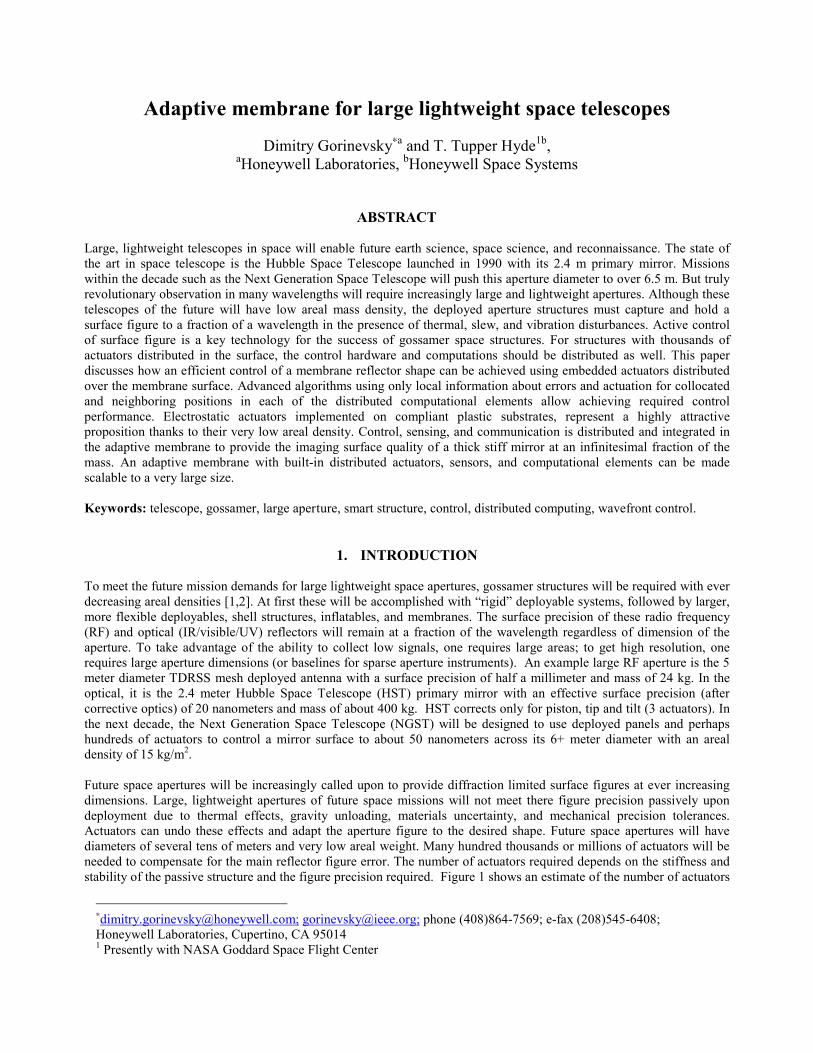
required versus aperture size and areal density based on the equations from [20]. The number of actuators required for agiven RMS surface deflection goes as the inverse of the thickness. In other words, to reduce the mass of a givenmembrane reflector by two requires four times as many actuators. A result of [20] is that the material modulus does notenter the equation… a stiffer material just requires more actuator forces to move and results in more “print-through”.Plastic is as good as metal or glass in this regard, but weighs significantly less.
Figure 1: Number of actuators required to hold surface precision RMS for a given aperture size (which equates to angular resolutionfor the telescope). Lines of constant thickness ratio are plotted and can be used to estimate mass of the reflecting membrane. A largelightweight structure such as a 200 kg, 50 meter IR reflector would require millions of actuators.
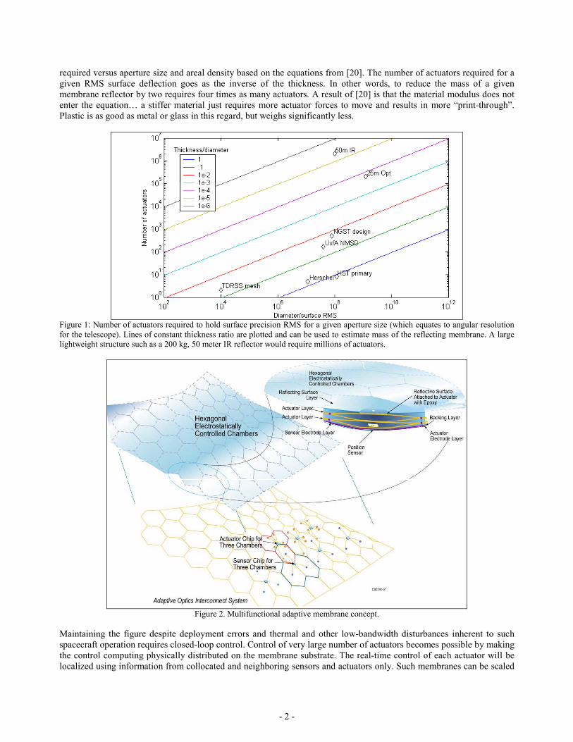
Figure 2. Multifunctional adaptive membrane concept.
Maintaining the figure despite deployment errors and thermal and other low-bandwidth disturbances inherent to suchspacecraft operation requires closed-loop control. Control of very large number of actuators becomes possible by makingthe control computing physically distributed on the membrane substrate. The real-time control of each actuator will belocalized using information from collocated and neighboring sensors and actuators only. Such membranes can be scaled
- 3 -
to a very large size with millions of actuators, each controlled independently of all but several neighbors.
Large lightweight apertures would be enabled by the mutifunctional adaptive membrane technology. A multifunctionaladaptive membrane envisioned in Figure 2 has built-in actuators, sensors, and controls. If produced in large quantities,the membrane can be made relatively inexpensively. It can be used as a subsystem when designing different missions. Itcan be used within lenticular inflatable space RF telescope antennas [3], mesh structures [4], and other spacecraftconcepts [5]. This paper describes developments of the control and system technology for such membranes.
2. SYSTEM-LEVEL DESIGN OF THE ACTIVE MEMBRANE
The system design of a multifunctional membrane follows from the required control functionality. The first task of theactive surface control is to initially figure the aperture after deployment. Once this initial “capture” of the figure isaccomplished, the bandwidth of the surface control depends on the time dependence of the disturbance sources. Designof distributed decentralized control architecture satisfying the above requirements is discussed later in this paper. Thekey conceptual hardware approaches to the membrane design including actuators, sensors, and computing infrastructureare discussed in the first subsection of this section. Choosing the specific design trades for the membrane follows fromthe control requirement specifications, which are discussed in the second subsection.
2.1 Hardware Concept
Membrane substrateFor space telescope primary mirrors over 20 meters in diameter, it is hard to imagine any structure other than a plasticbased membrane. There are several polyimide membranes from Dupont and SRS that are space qualified and can hold anoptical surface quality [6]. The choice of thickness of the membrane is driven by several factors including folding-packing, tensioning, thermal environment and life. But by far, the most influential factor in the surface quality underactive control is the number and spacing of actuators. A large number of actuators reduces the force that any oneactuator must place on the membrane surface and therefore reduced “print-through” or local deformations due to a singleactuator. Of course, the penalty of large numbers of actuators is the cost, mass, and control complexity. It is exactly thesethree issues that are addressed by the adaptive membrane concept described in this paper.
ActuatorsHoneywell developed the unique polymer electrostatic actuator technology under several DARPA contracts. Thistechnology could provide an actuator force of 1 N/cm2 over 100 µm displacement with an actuator cell size of 1-3 cm,and thickness of folded membrane of 100-200 µm. The areal density of such membrane would be less than 0.2 kg/m2. Asdemonstrated in [7,8,9,10], an electrostatic mechanism is very adequate for building large 2-D and 3-D arrays of low-weight, low-power actuators. An electrostatic actuator is essentially a capacitor. The actuating elements are theelectrodes and the dielectric layer. The power consumption of one actuator node in a static condition is very small.
While electrostatic actuation is generally known as a high-voltage/low-displacement mechanism, Honeywell actuatorshave large strokes (hundreds of microns) and work with low voltages (between 50 and 150 V). The enabler is a rollingcontact, which allows spatial separation of the maximum force and maximum displacement. The force responsible forthe movement is produced at the tip of the rolling contact while the maximum displacement is obtained at a differentlocation, which could be the free end of a flap or the center of a buckled diaphragm. Valves, pumps, and muscle-likestructures based on rolling contact electrostatic actuators were demonstrated, all of them using plastic substrates such asa Kapton film [8,9]. More detail about applicability of these actuators to control of reflector membranes can be found in[10].
Figure error measurement issuesAn imaging system with a membrane reflector must provide a measurement of the figure error for use as a feedbacksignal in the figure control loop. Traditionally, telescopes with adaptive optics use wavefront-sensing methods to controla deformable secondary mirror and correct for the atmospheric distortions. These distortions have low spatial and highdynamical frequency. In contrast, space imaging requires shaping of the primary mirror figure under temperature andmechanical disturbances that have high spatial and low dynamical frequency. The envisioned adaptive membrane will
- 4 -
have local deformation sensors in each cell of the membrane and a centralized wavefront sensor. These sensors havetheir own inaccuracies, and the overall synthetic measurement will be obtained by fusing diverse sensor data. As localsensors, capacitive sensors, strain gauges, or fiber-optic curvature sensors can be used. As central sensors of the figureerror, a Twyman-Green interferometer or a Shack-Hartmann sensor on the secondary mirror can be employed.
ComputingThe computational architecture of the adaptive membrane has to be designed such that it is scalable to support millionsof the actuators. This can hardly be achieved with a centralized computer because of a need to provide control signalsand control power to millions of actuators simultaneously. A scalable concept of the computing and controlinfrastructure for the active membrane is illustrated in Figure 2. There are simple computational elements distributedover the membrane, one for each cell or cluster of cells. Each element has relatively low computing power andcommunicates directly with its nearest neighbors only. At the same time, the sheer number of such elements createssignificant distributed computing power. The central processor (or processor cluster) of the telescope will have a high-speed connection to the central sensor(s) of the figure error. It can also communicate with the distributed computingelements. With direct connection to the elements on the reflector rim only, such communication will be performedthrough the mesh network of distributed neighbor-to-neighbor connections and will have low bandwidth. The computingpower and communication constraints define partitioning for the computing algorithms discussed in the next section. .
2.2 Control specifications
The main top-level specification requirement in the control system design is given by the disturbance rejectionbandwidth. An active membrane surface of a large reflector can be considered as a multidimensional system with twospatial dimensions and a time dimension. The control specification requirements for the membrane have to characterizethe spatial as well as dynamical disturbance rejection capability (bandwidth).
In the astronomical community, the spatial bandwidth constraints are most often encountered and understood with regardto adaptive optics systems design. The ultimate spatial bandwidth constraint is given by the spatial Nyquist frequencythat corresponds to the spatial disturbances with wavelength of twice the actuator spacing. The spatial disturbances withwavelengths shorter than the Nyquist cannot possibly be controlled. If the spatial response of the actuator is broad andspans multiple cells, then the spatial bandwidth might be further reduced compared to the Nyquist frequency [11]. Theresponse shape is an important characteristic influencing the spatial disturbance controllability. Too narrow a responsecan lead to spatial frequency impostoring effect that is well studied in the usual time-domain sampled-time systemstheory [12]. Choosing actuator and membrane parameters to achieve proper response width is an important part of thesystem design trades. For large ground or space telescopes the need for high spatial bandwidth and, thus, dense actuatorspacing is defined by a few factors. One of them is that the telescope ultimately should provide a high quality image atan imaging sensor that has a resolution of several megapixels. Hence, a few millions of actuators might be needed tocompensate for the figure errors and provide the required resolution. Another requirement is compensating the spatialdisturbances to provide sufficiently high quality of the wavefront and hence high Strehl number for the instrument.
The disturbances of the reflector figure include the initial deployment errors of the figure, dimpling, and surfaceroughness for the membrane. These are purely spatial disturbances with zero bandwidth in time. Thermal deformationsof the surface shape will have very low bandwidth defined by the orbit time for low Earth orbit telescope or by thetypical rates of the major attitude changes of the spacecraft. Other time-varying disturbances will include micro-gravity,gravity gradients, and solar pressure. The high-bandwidth disturbances might include jitter caused by working reactionwheels of spacecraft attitude control system. The orbit and sun shading might be benign enough to allow only periodicre-figuring without any significant loss of mission time. In earth orbit, or where significant attitude slewing is required,the figure control will be required to be active during use of the aperture. Thermal time constants would be on the orbitaltime scale, slew acceleration induced disturbance have time constants based on vehicle agility, and spacecraft busvibration disturbances are at many frequencies up to hundreds of Hz.
The membrane would compensate only for the disturbances with low dynamical bandwidth. Active compensation of thevibrations is hardly practical and they have to be dealt with by designing the membrane to provide a sufficient passivedamping. A primary reflector with the controllable membrane will be an active optics system with low-bandwidth, slowcompensation of the figure errors. This is similar to the design of the active main mirror for the NGST and differs fromthe adaptive optics systems that must have high dynamical bandwidth.
- 5 -
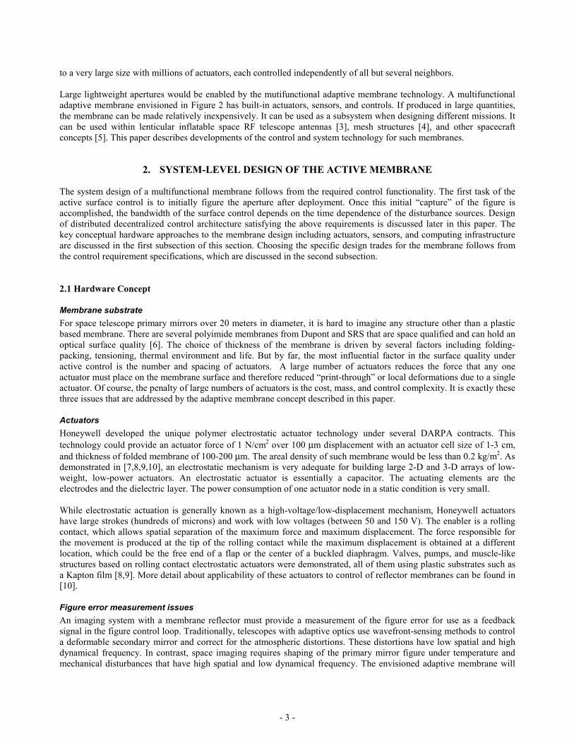
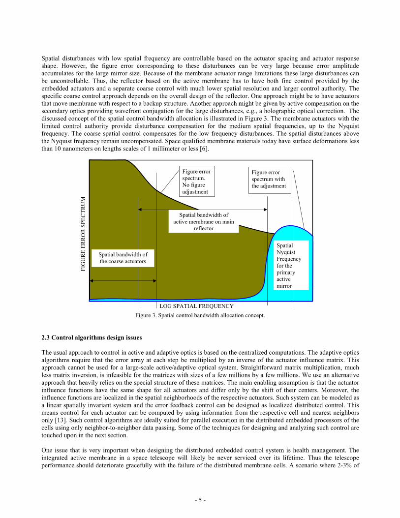
Spatial disturbances with low spatial frequency are controllable based on the actuator spacing and actuator responseshape. However, the figure error corresponding to these disturbances can be very large because error amplitudeaccumulates for the large mirror size. Because of the membrane actuator range limitations these large disturbances canbe uncontrollable. Thus, the reflector based on the active membrane has to have both fine control provided by theembedded actuators and a separate coarse control with much lower spatial resolution and larger control authority. Thespecific coarse control approach depends on the overall design of the reflector. One approach might be to have actuatorsthat move membrane with respect to a backup structure. Another approach might be given by active compensation on thesecondary optics providing wavefront conjugation for the large disturbances, e.g., a holographic optical correction. Thediscussed concept of the spatial control bandwidth allocation is illustrated in Figure 3. The membrane actuators with thelimited control authority provide disturbance compensation for the medium spatial frequencies, up to the Nyquistfrequency. The coarse spatial control compensates for the low frequency disturbances. The spatial disturbances abovethe Nyquist frequency remain uncompensated. Space qualified membrane materials today have surface deformations lessthan 10 nanometers on lengths scales of 1 millimeter or less [6].
Spatial bandwidth ofthe coarse actuators
Spatial bandwidth ofactive membrane on main
reflector
Figure errorspectrum.No figureadjustment
Figure errorspectrum withthe adjustment
LOG SPATIAL FREQUENCY
FIG
UR
E ER
RO
R S
PEC
TRU
M
SpatialNyquistFrequencyfor theprimaryactivemirror
Figure 3. Spatial control bandwidth allocation concept.
2.3 Control algorithms design issues
The usual approach to control in active and adaptive optics is based on the centralized computations. The adaptive opticsalgorithms require that the error array at each step be multiplied by an inverse of the actuator influence matrix. Thisapproach cannot be used for a large-scale active/adaptive optical system. Straightforward matrix multiplication, muchless matrix inversion, is infeasible for the matrices with sizes of a few millions by a few millions. We use an alternativeapproach that heavily relies on the special structure of these matrices. The main enabling assumption is that the actuatorinfluence functions have the same shape for all actuators and differ only by the shift of their centers. Moreover, theinfluence functions are localized in the spatial neighborhoods of the respective actuators. Such system can be modeled asa linear spatially invariant system and the error feedback control can be designed as localized distributed control. Thismeans control for each actuator can be computed by using information from the respective cell and nearest neighborsonly [13]. Such control algorithms are ideally suited for parallel execution in the distributed embedded processors of thecells using only neighbor-to-neighbor data passing. Some of the techniques for designing and analyzing such control aretouched upon in the next section.
One issue that is very important when designing the distributed embedded control system is health management. Theintegrated active membrane in a space telescope will likely be never serviced over its lifetime. Thus the telescopeperformance should deteriorate gracefully with the failure of the distributed membrane cells. A scenario where 2-3% of
- 6 -
the nodes have failed is realistic for a long duration mission. This would mean 20,000-30,000 failed cells out of 1million. The acute fault causes can include mechanical damage caused by micrometeorites and ionizing radiationdamage of the circuits in the embedded electronics. The faults might include sensor faults, actuator faults, power supplysystem (e.g., power line) faults, loss of communication links between neighbors, and failure of computing nodes. Thesefaults have to accommodated by re-routing communication around the failed links and nodes and reconfiguring control.The reconfiguration of control logic (control mode change) might allow recovering lost data from a ‘dead’ cell byinterpolating the data from the neighboring cells.
3. DISTRIBUTED LOCALIZED CONTROL – ANALYSIS
An active membrane with embedded actuators, sensors, and computational elements represents an array control system.In such system variables, measurement, and control change in time and depend on spatial coordinates. Multidimensionalsignal processing for large sensor arrays has well-established theory and applications, especially in imaging. Yet, appliedapproaches to distributed localized control of large distributed actuator and sensor arrays are less well known and belongto the cutting edge of current control technology. Some of our earlier work in control of arrays with hundreds ofactuators and developed analysis tools can be found in [14-17].
3.1 Issues and approaches
The distributed localized control techniques are applicable to a broad variety of adaptive membrane designs usingdifferent actuation and sensing principles. For the sake of analysis, the entire membrane surface is subdivided intoidentical cells, each containing one or more sensors and actuators. Each cell has a control module computing control as aweighted sum of past control and sensor measurement errors for it and several neighboring cells. Such real-timedistributed localized control calculations are straightforward and can be realized in simple control module hardware.
Design and analysis of such a controller goes beyond standard control technology. Modeling, analysis, and controldesign for the membrane system are based on multidimensional systems theory [18]. Spatially distributed systems can beanalyzed by modal decomposition such that the time dynamics of each mode is handled separately. For array systems,where identical multifunctional cells make a regular spatial grid, a modal decomposition is given by a spatial Fourierexpansion [13]. This leads to spatial frequency analysis somewhat related to the frequency domain analysis used instandard control problems [19]. The multidimensional frequency analysis is applicable to very large array systemswithout any increase in complexity. Such analysis allows rigorous computation and allocation of spatial and dynamicalbandwidth of the control system [14-17]. Recognizing spatial bandwidth limitations is related to the practice ofdiscarding higher order spatial modes that are poorly controllable. The modal control, however, requires centralizedcomputations with access to all measurements and actuator commands. The distributed array control is designed usingonly spatially localized information from near neighbor nodes in the array [14-17].
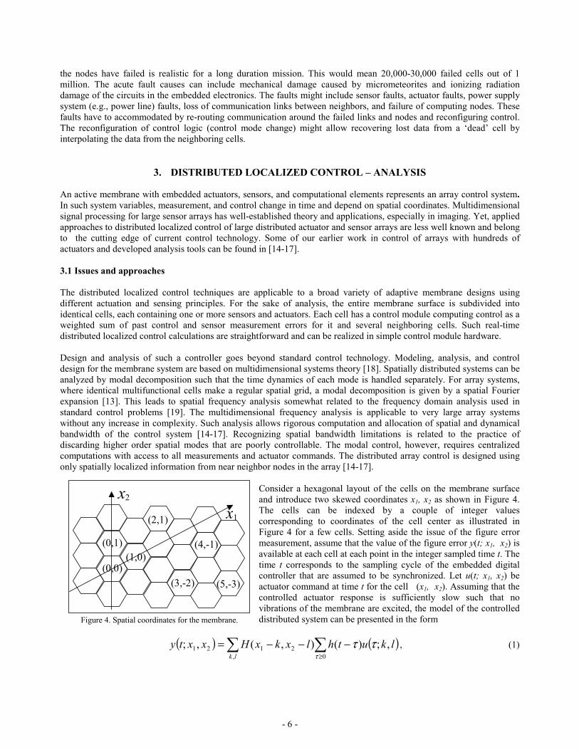
Consider a hexagonal layout of the cells on the membrane surfaceand introduce two skewed coordinates x1, x2 as shown in Figure 4.The cells can be indexed by a couple of integer valuescorresponding to coordinates of the cell center as illustrated inFigure 4 for a few cells. Setting aside the issue of the figure errormeasurement, assume that the value of the figure error y(t; x1, x2) isavailable at each cell at each point in the integer sampled time t. Thetime t corresponds to the sampling cycle of the embedded digitalcontroller that are assumed to be synchronized. Let u(t; x1, x2) beactuator command at time t for the cell (x1, x2). Assuming that thecontrolled actuator response is sufficiently slow such that novibrations of the membrane are excited, the model of the controlleddistributed system can be presented in the form
( ) ( )lkuthlxkxHxxtylk
,;)(),(,;0,
2121 τττ
−−−= ∑∑≥
, (1)
x2
x1
(0,0)(1,0)
(0,1)
(2,1)
(3,-2) (5,-3)
(4,-1)
Figure 4. Spatial coordinates for the membrane.
- 7 -
where H(t; x1, x2) is the spatial pulse response function that describes the shape of the membrane surface deformation ifone of the actuators is pulsed (bumped). The time pulse response h(t; x1, x2) in (1) describes the actuators dynamics thatare considered to be the same for all actuators. The model (1) is sufficiently comprehensive and allows describing mostof high-resolution active and adaptive optics systems.
The control design and analysis for the system (1) is facilitated by introducing the multidimensional transfer functions
( ) τ
ττλλλλ −
≥
−− ∑∑ == zhzglkHG lk
lk)()(;),(,
021
,21 , (2)
where z is the usual operational variable for the discrete Laplace transform (z-transform) and g(z) is the transfer functionof the actuators, as usual z-1 can be considered as a unit delay operator. In a similar way, λ1 and λ2 are spatial Laplacevariables corresponding to the operators of unit shift along the axes x1 and x2. Unlike the time dependencies, the spatialdependencies in the system are non-causal and the theory of two sided Laplace transform (or z- transform) must be used.The spatial transfer function G(λ1, λ2) of the actuators is non-causal.
The multidimensional model of the system (1) can be, thus, presented in the form
uzgGy )(),( 21 λλ= (3)
Many of familiar concepts of control design and analysis can be extended to the multidimensional control systems. Onekey concept is control robustness to modeling error – both in description of dynamical and spatial response of thesystem. For rigorous analysis of the robustness to models of both dynamical and spatial response of the system, we use amultidimensional extension [14] of structured singular value analysis (µ-analysis) [19]. This analysis is extended toallow for description of the boundary effects on the edges of the array. The robustness analysis is also used in thedistributed localized control design to take into account the unmodeled flexible dynamics of the membrane.
3.2 Example
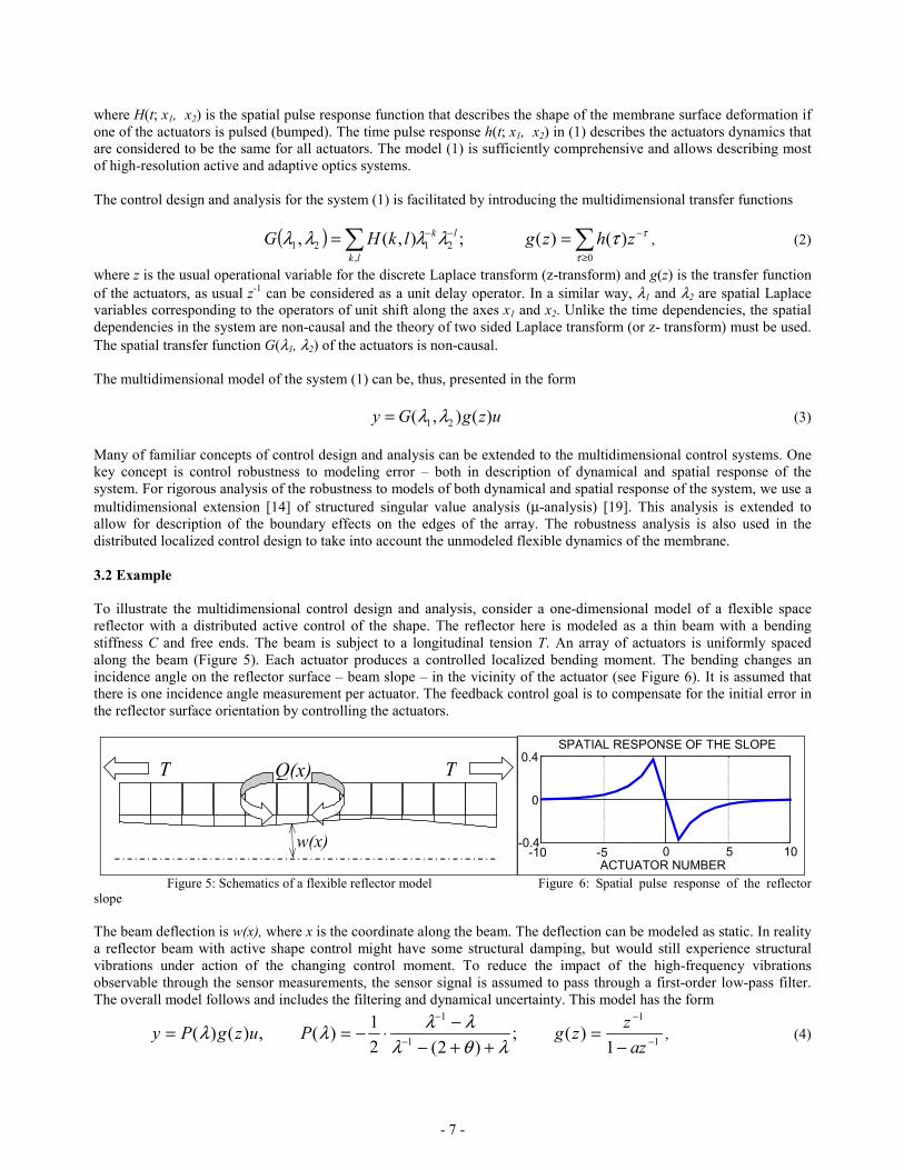
To illustrate the multidimensional control design and analysis, consider a one-dimensional model of a flexible spacereflector with a distributed active control of the shape. The reflector here is modeled as a thin beam with a bendingstiffness C and free ends. The beam is subject to a longitudinal tension T. An array of actuators is uniformly spacedalong the beam (Figure 5). Each actuator produces a controlled localized bending moment. The bending changes anincidence angle on the reflector surface – beam slope – in the vicinity of the actuator (see Figure 6). It is assumed thatthere is one incidence angle measurement per actuator. The feedback control goal is to compensate for the initial error inthe reflector surface orientation by controlling the actuators.
Q(x)
w(x)
T T
-0.4
0
0.4
ACTUATOR NUMBER
SPATIAL RESPONSE OF THE SLOPE
-10 -5 0 5 10
Figure 5: Schematics of a flexible reflector model Figure 6: Spatial pulse response of the reflectorslope
The beam deflection is w(x), where x is the coordinate along the beam. The deflection can be modeled as static. In realitya reflector beam with active shape control might have some structural damping, but would still experience structuralvibrations under action of the changing control moment. To reduce the impact of the high-frequency vibrationsobservable through the sensor measurements, the sensor signal is assumed to pass through a first-order low-pass filter.The overall model follows and includes the filtering and dynamical uncertainty. This model has the form
1
1
1
1
1)(;
)2(21)(,)()( −
−
−
−
−=
++−−⋅−==
azzzgPuzgPy
λθλλλλλ , (4)
- 8 -
where P(λ) is a spatial response operator defined by (4) with pulse response (Green function) in Figure 6; a is adynamical exponential filtering factor. In the simulations, it was assumed that a=0.8 (filter time constant is 4-5 samples),and θ =T/C= 0.3 (moderate tension in the beam).
The controller for the system (3)—(4) was designed using a loopshaping technique similar to one discussed in [17]. Thegeneral form of the feedback controller is
,)()()()1( 111 uzSyKzcuz −−− −−=− λλ (5)
,)1()( 11IP kzkzc +−= −− (6)
where K(λ) and S(λ) are spatial operators and c(z-1) is a dynamical PI feedback controller in velocity form. Non-causalspatial FIR operators K(λ) and S(λ) are designed such that the information from three closest neighbors on each sideonly is used for control of each actuator. The operator K(λ) is chosen to equalize the loop gain across the controllablespatial frequencies while the operator S(λ) is chosen to prevent large control action for the uncontrollable frequencies.These operators were designed based on the spatial operator P(λ) in the plant (3). Such design allows for localizedfeedback control computations to be implemented in distributed control elements. In simulations below the followingoperators were used
321-2-3-
32-1-2-3
0.1148 0.16360.3336-0.6196 0.3336- 0.16360.1148)(0.09720.31101.459501.45950.3110-0.0972 )(
λλλλλλλλλλλλλλ
++++=−+−++=
SK
, (7)
The PI dynamical feedback controller gains are kP=0.15, kI=0.07, such that a good quality of the transient process anddisturbance rejection is achieved while the required degree of robustness is maintained.
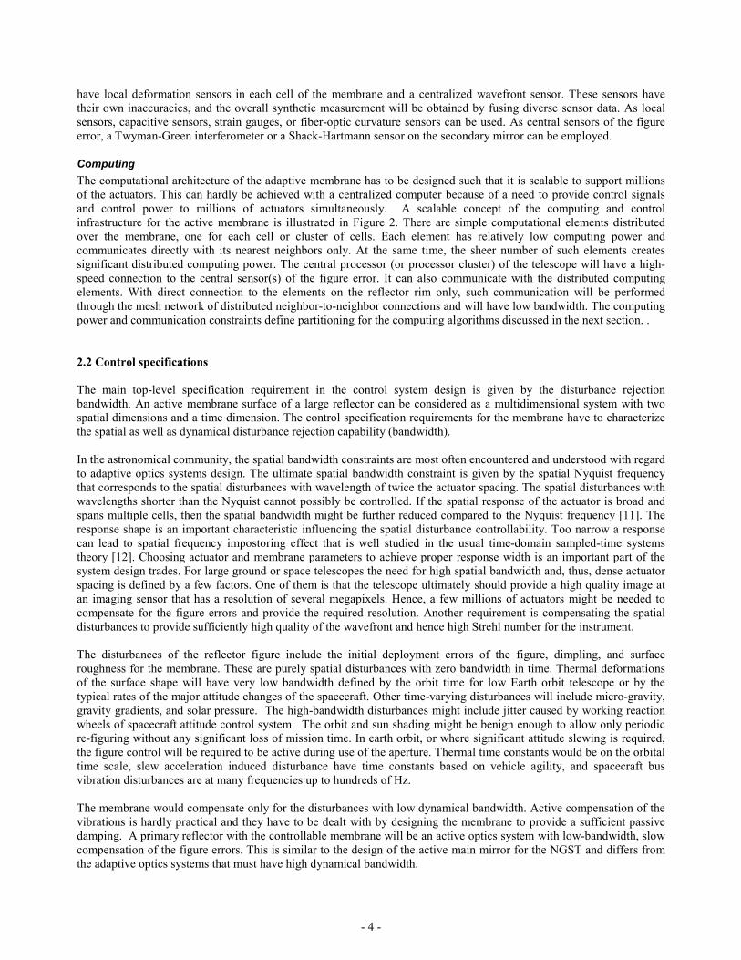
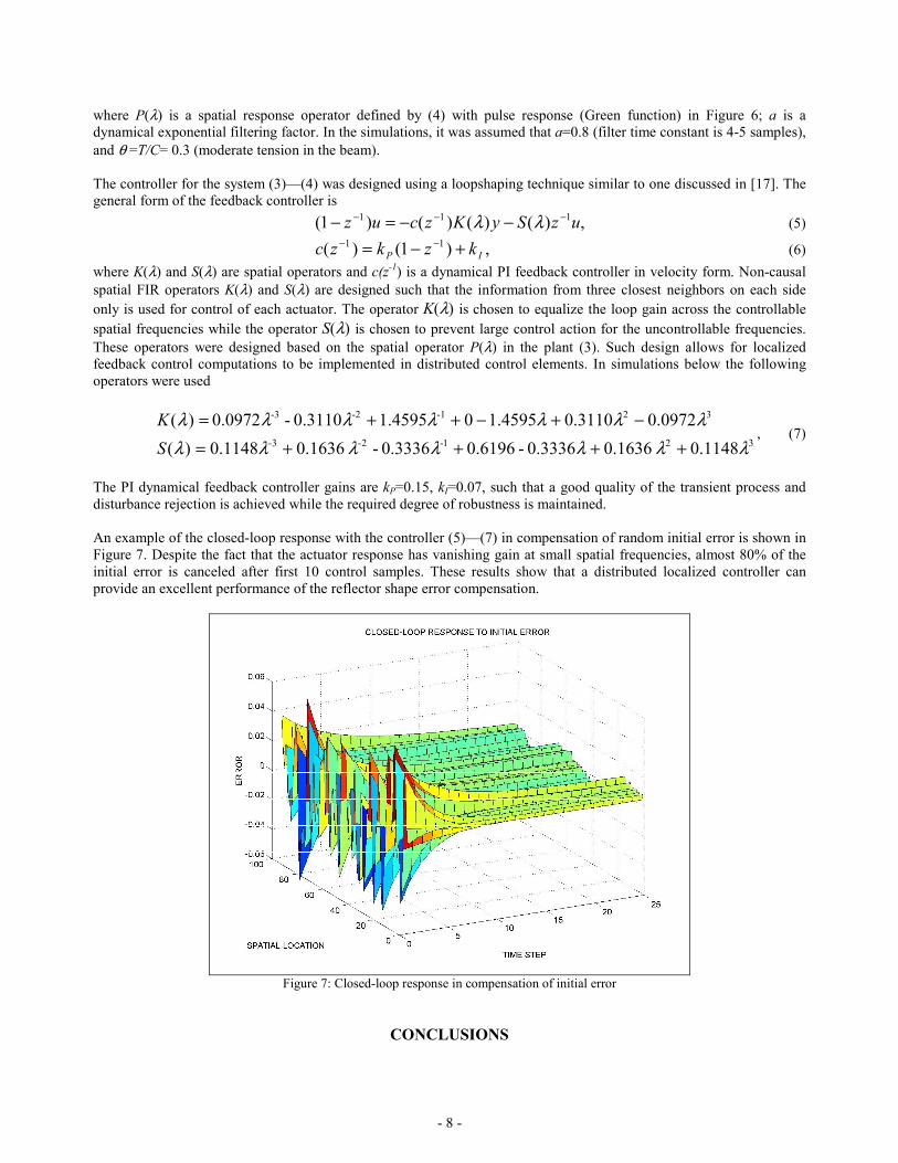
An example of the closed-loop response with the controller (5)—(7) in compensation of random initial error is shown inFigure 7. Despite the fact that the actuator response has vanishing gain at small spatial frequencies, almost 80% of theinitial error is canceled after first 10 control samples. These results show that a distributed localized controller canprovide an excellent performance of the reflector shape error compensation.
Figure 7: Closed-loop response in compensation of initial error
CONCLUSIONS

- 9 -
Effective surface precision control of future lightweight membrane space reflectors will require large numbers ofactuators distributed over the membrane. A multifunctional adaptive membrane concept is presented which meets theseneeds by embedding large numbers of actuators in the membrane. With distributed localized control, effective surfaceprecision is maintained without massive complexity in the control computations. Instead, the computations areperformed in paralell in many simple embedded computing elements physically distributed over the membrane surface.Only knowledge from local and a few nearest neighbors is required for the computations.
REFERENCES
1. Chmielewski, A.B., Moore, C., Howard, R. “The gossamer initiative,” IEEE Aerospace Conference, Big Sky, MT,March 2000.
2. Montgomery E.E., “Variance of ultralightweight space telescope technology development priorities with increasingtotal aperture goals,” 1999 Ultra Lightweight Space Optics Workshop, Napa Valley, CA, March 1999
3. Chmielewski, A.B., Noca, M.A., Ulvestad, J. “ARISE antenna,” IEEE Aerospace Conf., Big Sky, MT, March 2000.4. Njoku, E., Wilson, W., Yueh, S., Freeland, R., Helms, R., et al. “Large deployable-mesh antenna system for ocean
salinity and soil moisture sensing,” IEEE Aerospace Conf., Big Sky, MT, March 2000.5. Lake, M.S., Peterson, L.D., Mikulas, M.M., et al “Structural concepts and mechanics issues for ultra-large optical
systems,” 1999 Ultra Lightweight Space Optics Workshop, Napa Valley, CA, March 19996. Angel, R., Burge, J., Hege, K, Kenworthy, M.A. and Woolf, N., “Stretched membrane with electrostatic curvature
(SMEC): A new technology for ultra-lightweight space telescopes,” UV, Optical, and IR Space Telescopes andInstruments, Proc. SPIE, 4013, 2000.
7. Cabuz, C., Cabuz, E.I., Ohnstein, T.R., Neus, J., Maboudian, R. “Factors enhancing the reliability of touch-modeelectrostatic actuators,” Sensors and Actuators, Vol. 79, 2000, pp. 245-250.
8. Cabuz, C., Cabuz, E.I., Rolfer, T., Herb, W., Zook, D. “Mesoscopic sampler based on 3-D array of electrostaticallyactivated diaphragms,” 10th Int. Conf. on Solid-State Sensors and Actuators, Transducers’99, June 1999, Sendai,Japan
9. Horning, R., Johnson, B. “Polymer-based MEMS actuators for biomimetics”, Neurotechnology for BiomimeticRobots, 14-16 May, 2000
10. Gorinevsky, D., Hyde, T., Cabuz, C., “Distributed shape control of lightweight space reflector structure,” IEEE Conf.on Decision and Control, Orlando, FL, Dec. 2001.
11. Gorinevsky, D., Heaven, M., and Vyse, B. “Performance analysis of cross-directional process control,” IEEE Tr. onControl Systems Technology, vol. 8, no. 4, July 2000, pp. 589—600.
12. A.V. Oppenheim, R.W. Schafer, and J.R. Buck, Discrete-Time Signal Processing, Prentice Hall, 199913. Bamieh, B., Paganini, F., and Dahleh, M. “Distributed control of spatially-invariant systems,” IEEE Trans. on
Automatic Control, 2002.14. Gorinevsky, D., and Stein G., “Structured uncertainty analysis of robust stability for multidimensional array
systems,” IEEE Tr. on Automatic Control, to appear.15. Stewart, G., Gorinevsky, D., and Dumont, G. "Design of a practical robust controller for a sampled distributed
parameter system," 37th IEEE Conf. on Decision and Control, Tampa, FL, Dec. 1998.16. Stewart, G.E., Gorinevsky, D., and Dumont, G.A., “H2 loopshaping controller design for spatially distributed
systems,” IEEE Conference on Decision and Control, Phoenix, AZ, December 199917. Stewart, G.E., Gorinevsky, D., and Dumont, G.A., “Spatial loopshaping: A case study on cross-directional profile
control,” American Control Conf., pp. 3098—3103, San Diego, CA, June 1999.18. N.K. Bose, Applied Multidimensional Systems Theory, Van Nostrand Reynhold, 1982.19. K. Zhow, Doyle, J., and Glover, K., Robust and Optimal Control, Prentice Hall, 199920. Burge, J. and Cuerden, B. “Design considerations for active membrane mirrors”, 1999 Ultra Lightweight Space
Optics Workshop, Napa Valley, CA, March 1999