
Design of Roadside Channels with Flexible · PDF fileDesign of Roadside Channels with Flexible...
150
Design of Roadside Channels with Flexible Lining HEC 15 April 1988 Metric Version Welcome to HEC 15 - Design of Roadside Channels With Flexible Linings Table of Contents Preface Tech Doc U.S. - SI Conversions DISCLAIMER: During the editing of this manual for conversion to an electronic format, the intent has been to convert the publication to the metric system while keeping the document as close to the original as possible. The document has undergone editorial update during the conversion process.
Transcript of Design of Roadside Channels with Flexible · PDF fileDesign of Roadside Channels with Flexible...
Design of Roadside Channels with Flexible Lining HEC 15 April 1988 Metric Version
Welcome to HEC 15 - Design of Roadside Channels With Flexible Linings
Table of Contents
Preface
Tech Doc
U.S. - SI Conversions
DISCLAIMER: During the editing of this manual for conversion to an electronic format, the intenthas been to convert the publication to the metric system while keeping the document as close to theoriginal as possible. The document has undergone editorial update during the conversion process.

Table of Contents for HEC 15-Design of Roadside Channels with Flexible Linings(Metric)
List of Figures List of Tables List of Charts & Forms List of Equations
Cover Page : HEC 15-Design of Roadside Channels with Flexible Linings (Metric)
Chapter 1 : HEC 15 Introduction
Chapter 2 : HEC 15 Background Lining Types Flexible Linings
Performance Characteristics
Information on Flexible Linings Permanent Flexible Linings
Temporary Flexible Linings
Chapter 3 : HEC 15 Design Concepts Open-Channel Flow Concepts
Resistance to Flow
Channel Bends
Freeboard
Stable Channel Design Concepts Equilibrium Concepts
Tractive Force Theory
Design Parameters Design Discharge Frequency
Channel Cross Section Geometry
Channel Slope
Chapter 4 : HEC 15 Design Procedure Design Procedure Flexible Lining Design
Permissible Shear Stress
Determination of Normal Flow Depth
Manning's Roughness Coefficients for Non-Vegetative Linings
Manning's Roughness Coefficients for Vegetative Linings
Determination of Shear Stress on Channel
Side Slope Stability
Maximum Discharge Approach
Design Considerations for Riprap Lining
Riprap Gradation and Thickness
Filter Design
Design Procedure Flexible Lining Design Procedure
Maximum Discharge Design Procedure Example Problems Example #1
Example #2
Example #3
Trial 1
Trial 2
Trial 3
Example #4
Trial 1
Trial 2
Example #5
Trial 1
Trial 2
Example #6
Example #7
Example #8
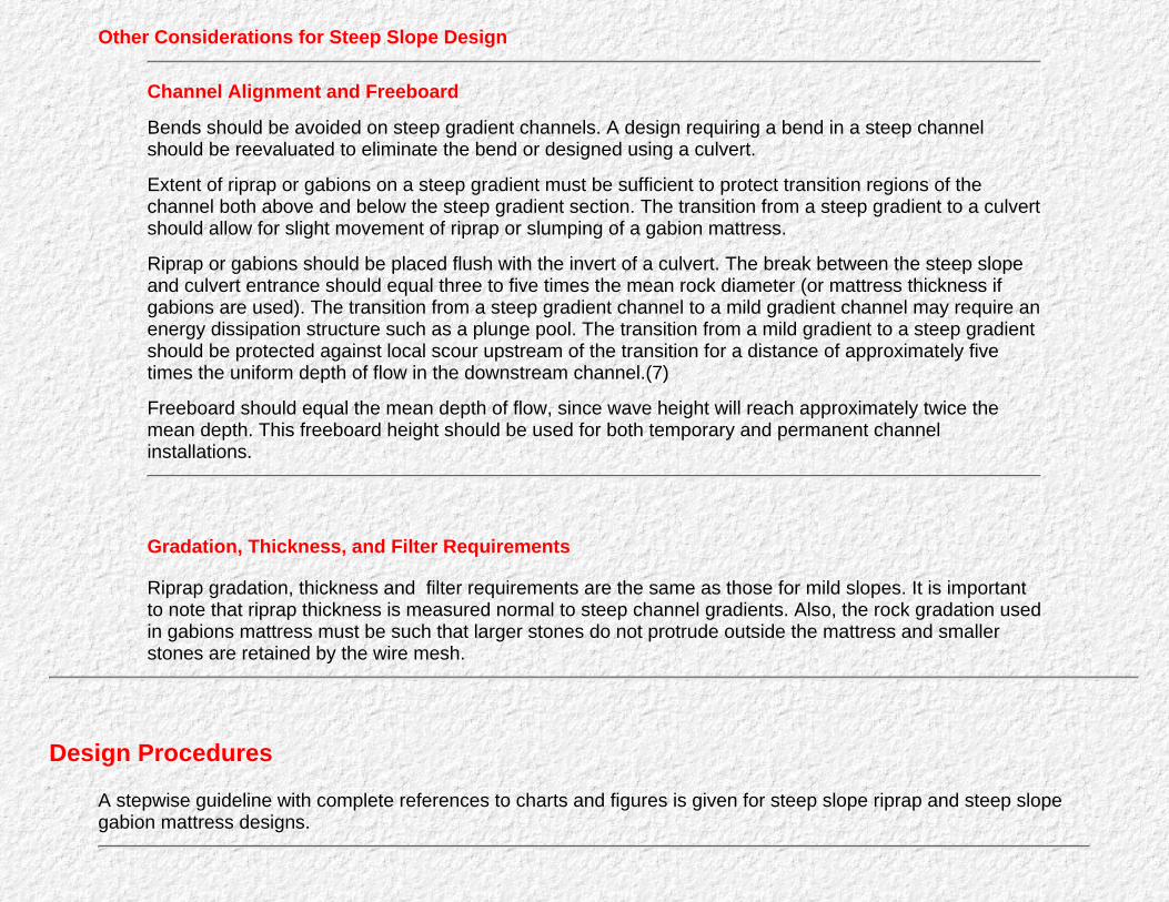
Chapter 5 : HEC 15 Steep Gradient Channel Design Steep Gradient Channel Design Steep Slope Design Gradation, Thickness, and Filter Requirements
Design Procedures Steep Slope Riprap Design Procedure
Steep Slope Gabion Mattress Design
Example Problems Example #9
Example #10
Example #11
Example #12
Chapter 6 : HEC 15 Design Composite Lining Composite Lining Design Special Considerations Design Procedure Composite Lining Design Procedure
Example Problem

Example #13:
Appendix A : HEC 15 Equations for Various Channel Geometries
Appendix B : HEC 15 Development of Design Charts and Procedures Resistance Equations
Appendix C : HEC 15 Development of Steep Gradient Design Charts and Procedures General Bathurst Resistance Riprap Stability Solution Procedure
Appendix D : HEC 15 Suggested Guideline Specifications Riprap Description
Materials
Construction Requirements
Measurement for Payment
Basis for Payment
Wire Enclosed Riprap Description
Materials
Construction Requirements
Measurement for Payment
Basis for Payment
Woven Paper Net Description
Materials
Construction Requirements
Measurement for Payment
Basis for Payment
Jute Net Description
Materials
Construction Requirements
Measurement for Payment
Basis for Payment
Fiberglass Roving Description
Materials

Construction Requirements
Measurement for Payment
Basis for Payment
Curled Wood Mat Description
Materials
Construction Requirements
Measurement for Payment
Basis for Payment
Straw with Net Description
Materials
Construction Requirements
Measurement for Payment
Basis for Payment
Synthetic Mat Description
Materials
Construction Requirements
Measurement for Payment
Basis for Payment
Filter Blanket Description
Materials
Construction Requirements
Measurement for Payment
Basis for Payment
Engineering Fabric Description
Materials
Construction Requirements
Measurement for Payment
Basis for Payment
Glossary
References
Symbols

List of Figures for HEC 15-Design of Roadside Channels with Flexible Linings (Metric)
Back to Table of Contents
Figure 1. Rigid Concrete Channel Lining
Figure 2. Composite Channel Lining (riprap and jute net)
Figure 3. Vegetative Channel Lining (class D retardance)
Figure 4. Riprap Channel Lining
Figure 5. Wire-Enclosed Riprap
Figure 6. Gravel Channel Lining
Figure 7. Woven Paper Net Channel Lining
Figure 8. Installed Woven Paper Net Lining
Figure 9. Jute Net Lining
Figure 10. Installed Jute Net Channel Lining
Figure 11. Fiberglass Roving Lining
Figure 12. Installation of Fiberglass Roving Along a Roadside
Figure 13. Curled Wood Mat
Figure 14. Installed Curled Wood Mat Channel Lining
Figure 15. Synthetic Mat Lining
Figure 16. Installed Synthetic Mat Channel Lining
Figure 17. Straw With Net Channel Lining
Figure 18. Typical Distribution of Shear Stress
Figure 19. Shear Stress Distribution in a Channel Bend (after 11)
Figure 20. Location Sketch of Flexible Linings for Example 5
Figure 21. Worksheet for Example Problems 4 and 5
Figure 22. Gradations of Granular Filter Blanket for Example 8
Figure 23. Worksheet for Flexible Lining
Figure 24. Worksheet for Example Problems 11 and 12
Figure 25. Worksheet for Steep Slope Channel Design
Figure 26. Compound Lining Example

Figure 27. Worksheet for Compound Lining Design
Figure 28. Worksheet for Example Problem 13
Figure 29. Equations for Various Channel Geometries
Figure 29. Equations for Various Channel Geometries
Figure 30. Manning's n versus Relative Roughness for Selected Lining Types.
Figure 31. Hydraulic Forces Acting on a Riprap Element
Figure 32. Steep Slope Design Procedure
Back to Table of Contents
Chapter 2 : HEC 15Background
Go to Chapter 3
Considerable development and research have been done on rigid and flexible channel linings.Prior to the late 1960's, natural materials were predominantly used to stabilize channels.Typical materials included rock riprap, stone masonry, concrete, and vegetation. Since thattime a wide variety of manufactured and synthetic channel linings applicable to both permanentand temporary channel stabilization have been introduced. Relatively little data on hydraulicperformances of these materials are available compared to the variety of materials produced.Work is continuing on comparing hydraulic performances, material improvement, and newmaterial development.
Lining Types
Because of the large number of channel stabilization materials currently available, it is useful toclassify these materials based on their performance characteristics. Lining types are classifiedas rigid, such as concrete, or flexible, such as vegetation or rock riprap. Flexible linings arefurther classified as temporary or permanent. Lining materials are classified as follows:
1. Rigid Linings:
Cast-in-place concreteCast-in-place asphalt concreteStone masonrySoil cementFabric form work systems for concreteGrouted riprap
2. Flexible linings
Permanent
Riprap Wire-enclosed riprap Vegetation lining Gravel
Temporary
Bare soil Straw with net Curled wood mat Jute, paper, or synthetic net

Synthetic mat Fiberglass roving.
Performance Characteristics
Rigid Linings
Rigid linings (Figure 1) are useful in flow zones where high shear stress ornon-uniform flow conditions exist, such as at transitions in channel shape or at anenergy dissipation structure. In areas where loss of water or seepage from thechannel is undesirable, they provide an impermeable lining. Since rigid linings arenon-erodible the designer can use any channel shape that adequately conveys theflow and provides adequate freeboard. This may be necessary if right-of-waylimitations restrict the channel size.
Figure 1. Rigid Concrete Channel Lining
Despite the non-erodible nature of rigid linings, they are highly susceptible to failurefrom structural instability. For example, cast-in-place or masonry linings often breakup and deteriorate if foundation conditions are poor. Once a rigid liningsdeteriorates, it is very susceptible to erosion because the large, flat, broken slabsare easily moved by channel flow.
The major causes of structural instability and failure of rigid linings are freeze-thaw,swelling, and excessive soil pore water pressures. Freeze thaw and swelling soilsexert upward forces against the lining and the cyclic nature of these conditions caneventually cause failure. Excessive soil pore pressure occurs when the flow levelsin the channel drop quickly. Side slope instability can develop from excessively highpore pressures and high hydraulic gradients along the slope surface.
Construction of rigid linings requires specialized equipment and costly materials. Asa result, the cost of rigid channel linings is high. Prefabricated linings can be a lessexpensive alternative if shipping distances are not excessive.

Flexible Linings
Riprap and vegetation are suitable linings for hydraulic conditions similar to thoserequiring rigid linings. Because flexible linings are permeable, they may requireprotection of underlying soil to prevent washout. For example, filter cloth is oftenused with riprap to inhibit soil piping.
Vegetative and temporary linings are suited to hydraulic conditions where uniformflow exist and shear stresses are moderate. Vegetative channel linings are notsuited to sustained flow conditions or long periods of submergence. Vegetativechannels with sustained low flow and intermittent high flows are often designed witha composite lining of a riprap or concrete low flow section, (Figure 2).
Figure 2. Composite Channel Lining (riprap and jute net)
Temporary linings provide erosion protection until vegetation is established. In mostcases the lining will deteriorate over the period of one growing season, whichmeans that successful re-vegetation is essential to the overall channel stabilizationeffort. Temporary channel linings may be used without vegetation to temporarilycontrol erosion on construction sites.
Information on Flexible Linings
The following is a summary of materials currently available for use as flexible channel linings.
Permanent Flexible Linings
Vegetation: Vegetative linings consist of planted or sodden grasses placed in andalong the drainage (Figure 3). If planted, grasses are seeded and fertilizedaccording to the requirements of that particular variety or mixture. Sod is laidparallel to the flow direction and may be secured with pins or staples.
Rock Riprap: Rock riprap is dumped in place on a filter blanket or prepared slopeto form a well-graded mass with a minimum of voids (Figure 4). Rocks should behard, durable, preferably angular in shape, and free from overburden, shale, and

organic material. Resistance to disintegration from channel erosion should bedetermined from service records or from specified field and laboratory tests.
Figure 3. Vegetative Channel Lining (class D retardance)
Figure 4. Riprap Channel Lining
Wire-Enclosed Riprap: Wire-enclosed riprap is manufactured from a rectangularcontainer made of steel wire woven in a uniform pattern, and reinforced on cornersand edges with heavier wire (Figure 5). The containers are filled with stone,connected together, and anchored to the channel side slope. Stones must be wellgraded and durable. The forms of wire- enclosed riprap vary from thin mattresses tobox-like gabions. Wire-enclosed riprap is typically used when rock riprap is eithernot available or not large enough to be stable.
Gravel Riprap: Gravel riprap consists of coarse gravel or crushed rock placed onfilter blankets prepared slope to form a well-graded mass with a minimum of voids(Figure 6). The material is composed of tough, durable, gravel-sized particles andshould be free from organic matter.
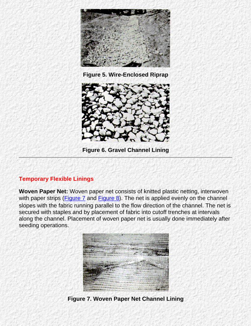
Figure 5. Wire-Enclosed Riprap
Figure 6. Gravel Channel Lining
Temporary Flexible Linings
Woven Paper Net: Woven paper net consists of knitted plastic netting, interwovenwith paper strips (Figure 7 and Figure 8). The net is applied evenly on the channelslopes with the fabric running parallel to the flow direction of the channel. The net issecured with staples and by placement of fabric into cutoff trenches at intervalsalong the channel. Placement of woven paper net is usually done immediately afterseeding operations.
Figure 7. Woven Paper Net Channel Lining
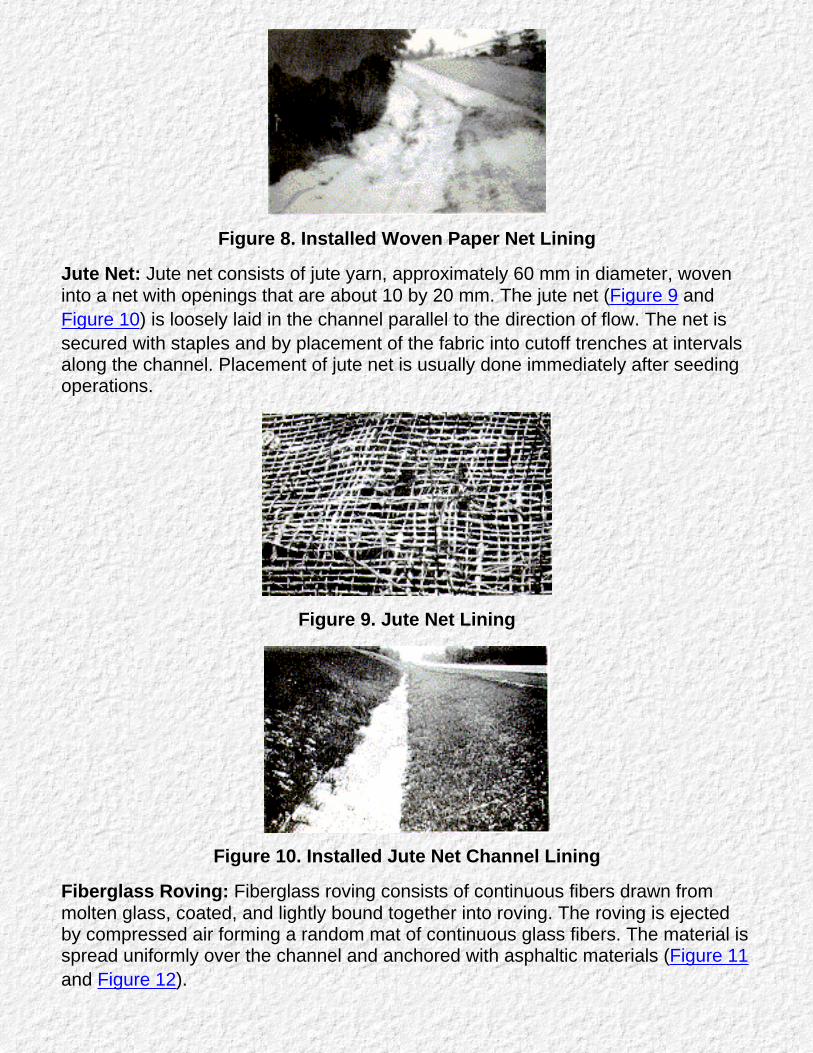
Figure 8. Installed Woven Paper Net Lining
Jute Net: Jute net consists of jute yarn, approximately 60 mm in diameter, woveninto a net with openings that are about 10 by 20 mm. The jute net (Figure 9 andFigure 10) is loosely laid in the channel parallel to the direction of flow. The net issecured with staples and by placement of the fabric into cutoff trenches at intervalsalong the channel. Placement of jute net is usually done immediately after seedingoperations.
Figure 9. Jute Net Lining
Figure 10. Installed Jute Net Channel Lining
Fiberglass Roving: Fiberglass roving consists of continuous fibers drawn frommolten glass, coated, and lightly bound together into roving. The roving is ejectedby compressed air forming a random mat of continuous glass fibers. The material isspread uniformly over the channel and anchored with asphaltic materials (Figure 11and Figure 12).
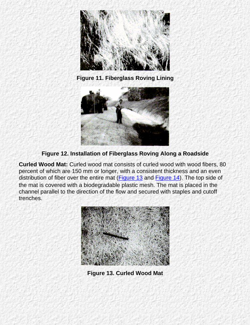
Figure 11. Fiberglass Roving Lining
Figure 12. Installation of Fiberglass Roving Along a Roadside
Curled Wood Mat: Curled wood mat consists of curled wood with wood fibers, 80percent of which are 150 mm or longer, with a consistent thickness and an evendistribution of fiber over the entire mat (Figure 13 and Figure 14). The top side ofthe mat is covered with a biodegradable plastic mesh. The mat is placed in thechannel parallel to the direction of the flow and secured with staples and cutofftrenches.
Figure 13. Curled Wood Mat
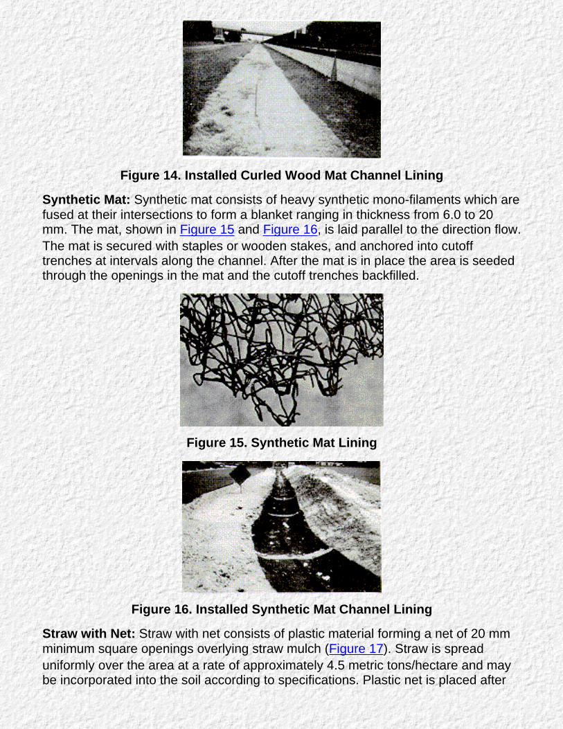
Figure 14. Installed Curled Wood Mat Channel Lining
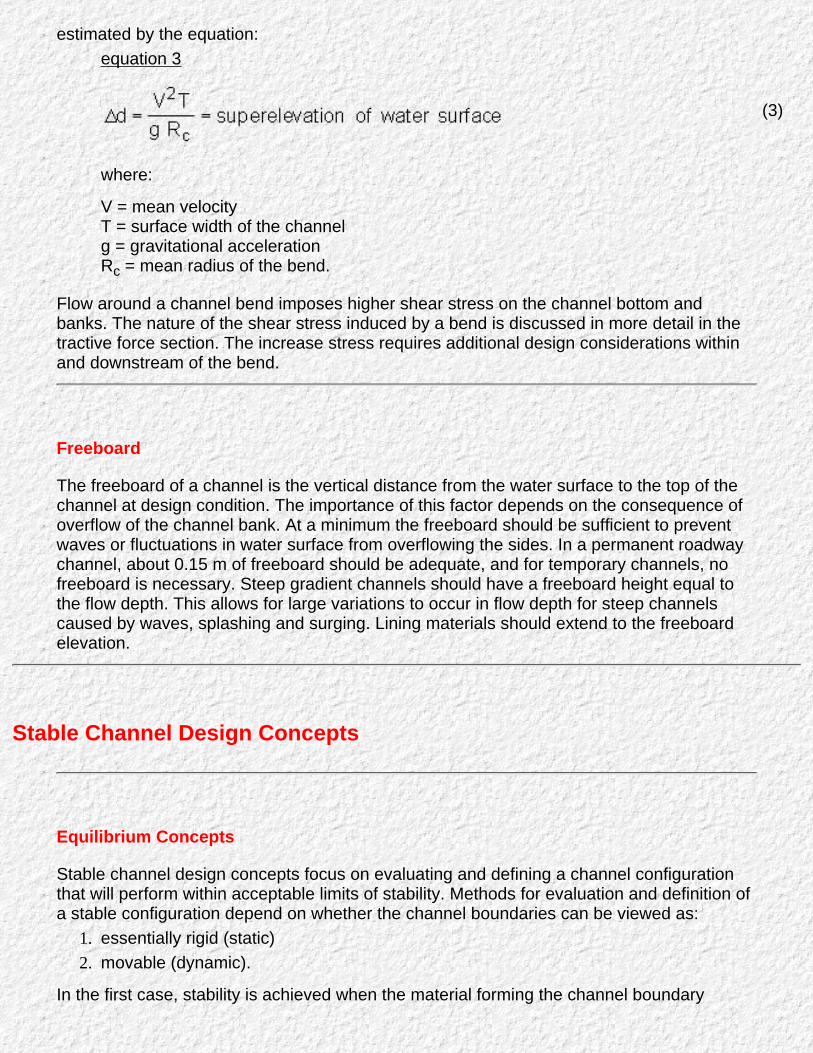
Synthetic Mat: Synthetic mat consists of heavy synthetic mono-filaments which arefused at their intersections to form a blanket ranging in thickness from 6.0 to 20mm. The mat, shown in Figure 15 and Figure 16, is laid parallel to the direction flow.The mat is secured with staples or wooden stakes, and anchored into cutofftrenches at intervals along the channel. After the mat is in place the area is seededthrough the openings in the mat and the cutoff trenches backfilled.
Figure 15. Synthetic Mat Lining
Figure 16. Installed Synthetic Mat Channel Lining
Straw with Net: Straw with net consists of plastic material forming a net of 20 mmminimum square openings overlying straw mulch (Figure 17). Straw is spreaduniformly over the area at a rate of approximately 4.5 metric tons/hectare and maybe incorporated into the soil according to specifications. Plastic net is placed after

mulching with straw to secure the mulch to the finished channel.
Figure 17. Straw With Net Channel Lining
Go to Chapter 3

Chapter 3 : HEC 15Design Concepts
Go to Chapter 4
The design method presented in this circular is based on the concept of maximum permissible tractiveforce, coupled with the hydraulic resistance of the particular lining material. The method includes twoparts, computation of the flow conditions for a given design discharge and determination of the degreeof erosion protection required. The flow conditions are a function of the channel geometry, designdischarge, channel roughness, and channel slope. The erosion protection required can be determinedby computing the shear stress on the channel at the design discharge and comparing the calculatedshear stress to the permissible value for the type of channel lining used.
Open-Channel Flow Concepts
Type of Flow
Open-channel flow can be classified according to three general conditions:uniform or non-uniform flow1.
steady or unsteady flow2.
subcritical or supercritical flow.3.
In uniform flow, the depth and discharge remain constant along the channel. In steady flow,no change in discharge occurs over time. Most natural flows are unsteady and aredescribed by runoff hydrographs. It can be assumed in most cases that the flow will varygradually and can be described as steady, uniform flow for short periods of time. Subcriticalflow is distinguished from super critical flow by a dimensionless number called the Froudenumber (Fr), which is defined as the ratio of inertial forces to gravitational forces in thesystem. Subcritical flow (Fr < 1.0) is characterized as tranquil and has deep, slower velocityflow. Supercritical flow (Fr > 1.0) is characterized as rapid and has shallow, high velocityflow.
For design purposes, uniform flow conditions are usually assumed with the energy slopeapproximately equal to average bed slope. This allows the flow conditions to be defined bya uniform flow equation such as Manning's equation. Supercritical flow creates surfacewaves that are approaching the depth of flow. For very steep channel gradients, the flowmay splash and surge in a violent manner and special considerations for freeboard arerequired.
Resistance to Flow
Depth of uniform flow in a channel depends on the roughness of a particular lining. Forpractical purposes in highway drainage engineering, Manning's equation provides a reliableestimate of uniform flow conditions. With a given depth of flow, d , the mean velocity may be

computed as:
V = R2/3 Sf1/2 (1)
where:
V = average velocity in the cross sectionn = Manning's roughness coefficientR = hydraulic radius, equal to the cross-sectional area, A, divided by the wetted perimeter,PSf = friction slope of the channel, approximated by the average bed slope for uniform flow
The discharge in the channel is given by the continuity equation as:
Q = AV (2)
where:
A = flow area in the channel.
For most types of channel linings Manning's roughness coefficient, n, is approximatelyconstant. The roughness coefficient will increase for very shallow flows where the height ofthe roughness features on the lining approaches the flow depth (see Appendix A). For ariprap lining, the flow depth in small channels may be only a few times greater than thediameter of the mean riprap size. In this case, use of a constant n value is acceptable, butconsideration of the shallow flow depth should be made by using a higher n value.
A channel lined with a good stand of vegetation cannot be described by a single n value.The resistance to flow in vegetated channels is further complicated by the fact thatvegetation will bend in the flow, changing the height of the vegetation. The SoilConservation Service (SCS) (4) developed a classification of vegetation depending on thedegree of retardance. Grasses are classified into five broad categories, as shown in Table 1in Chapter 4. Retardance Class A presents the highest resistance to flow and Class Epresents the lowest resistance to flow. In general, taller and stiffer grass species have ahigher resistance to flow, while short flexible grasses have a low-flow resistance.
Recent studies by Kouwen et al.(5,6), examined the biomechanics of vegetation andprovided a more general approach for determining the Manning's n value for vegetatedchannels. The resulting resistance equation (see Appendix B, equation 19) uses the samevegetative classification as the SCS but is more accurate for very stiff vegetation and mildchannel gradients. Design Chart 5, Chart 6, Chart 7, Chart 8, and Chart 9 were developedfrom the Kouwen resistance equation.
Channel Bends
Flow around a bend in an open channel induces centrifugal forces because of the change inflow direction.(7) This results in a superelevation of the water surface. The water surface ishigher at the outside of the bend than at the inside of the bend. This superelevation can be
estimated by the equation:equation 3
where:
V = mean velocityT = surface width of the channelg = gravitational accelerationRc = mean radius of the bend.
(3)
Flow around a channel bend imposes higher shear stress on the channel bottom andbanks. The nature of the shear stress induced by a bend is discussed in more detail in thetractive force section. The increase stress requires additional design considerations withinand downstream of the bend.
Freeboard
The freeboard of a channel is the vertical distance from the water surface to the top of thechannel at design condition. The importance of this factor depends on the consequence ofoverflow of the channel bank. At a minimum the freeboard should be sufficient to preventwaves or fluctuations in water surface from overflowing the sides. In a permanent roadwaychannel, about 0.15 m of freeboard should be adequate, and for temporary channels, nofreeboard is necessary. Steep gradient channels should have a freeboard height equal tothe flow depth. This allows for large variations to occur in flow depth for steep channelscaused by waves, splashing and surging. Lining materials should extend to the freeboardelevation.
Stable Channel Design Concepts
Equilibrium Concepts
Stable channel design concepts focus on evaluating and defining a channel configurationthat will perform within acceptable limits of stability. Methods for evaluation and definition ofa stable configuration depend on whether the channel boundaries can be viewed as:
essentially rigid (static)1.
movable (dynamic).2.
In the first case, stability is achieved when the material forming the channel boundary
effectively resists the erosive forces of the flow. Under such conditions the channel bed andbanks are in static equilibrium, remaining basically unchanged during all stages of flow.Principles of rigid boundary hydraulics can be applied to evaluate this type of system.
In a dynamic system, some change in the channel bed and/or banks is to be expected iferosive forces of the flow are sufficient to detach and transport the materials comprising thechannel boundary. Stability in a dynamic system is generally attained when the sedimentsupply rate equals the sediment transport rate. This condition, where sediment supplyequals sediment transport, is often referred to as dynamic equilibrium. Although somedetachment and transport of bed and/or bank materials may occur, this does not precludeattainment of a channel configuration that is basically stable. A dynamic system can beconsidered stable so long as the net change does not exceed acceptable levels. For mosthighway drainage channels, bank instability and possible lateral migration cannot betolerated. Consequently, development of static equilibrium conditions or utilization of liningsto achieve a stable condition is usually preferable to using dynamic equilibrium concepts.
Two methods have been developed and are commonly applied to determine if a channel isstable in the sense that the boundaries are basically immobile (static equilibrium). Thesemethods are defined as the permissible velocity approach and the permissible tractive force(shear stress) approach. Under the permissible velocity approach the channel is assumedstable if the adopted mean velocity is lower than the maximum permissible velocity. Thetractive force (boundary shear stress) approach focuses on stresses developed at theinterface between flowing water and materials forming the channel boundary. By Chow'sdefinition, permissible tractive force is the maximum unit tractive force that will not causeserious erosion of channel bed material from a level channel bed.(7)
Permissible velocity procedures were first developed around the 1920's. In the 1950's,permissible tractive force procedures became recognized, based on research investigationsconducted by the U.S. Bureau of Reclamation. Procedures for design of vegetated channelsusing the permissible velocity approach were developed by the SCS and have remained incommon use.
In spite of the empirical nature of permissible velocity approaches, the methodology hasbeen employed to design numerous stable channels in the United States and throughoutthe world. However, considering actual physical processes occurring in open-channel flow,a more realistic model of detachment and erosion processes is based on permissibletractive force .
Tractive Force Theory
The hydrodynamic force of water flowing in a channel is known as the tractive force . Thebasis for stable channel design with flexible lining materials is that flow-induced tractiveforce should not exceed the permissible or critical shear stress of the lining materials. In auniform flow, the tractive force is equal to the effective component of the gravitational forceacting on the body of water, parallel to the channel bottom.(7) The average tractive force onthe channel, or shear stress is equal to:
τ = γRS
(Where:
γ=Unit Weight of WaterR= Hydraulic RadiusS= Average Bed Slope or Energy Slope
(4)
The maximum shear stress, τd, for a straight channel occurs on the channel bed (7, 8) andis less than or equal to the shear stress at maximum depth.
τd = γdS
where:
d = maximum depth of flow.
(5)
Shear stress in channels is not uniformly distributed along the wetted perimeter. (9,10) Atypical distribution of shear stress in a trapezoidal channel tends toward zero at the cornerswith a maximum on the center line of the bed, and the maximum for the side slopesoccurring about the lower third of the side as shown in Figure 18. Flow around a bendcreates secondary currents, which impose higher shear stresses the channel sides andbottom compared to a straight reach (11) as shown in Figure 19 . At the beginning of thebend, the maximum shear stress is near the inside and moves toward the outside as theflow leaves the bend. The increased shear stress caused by a bend persists downstream ofthe bend, a distance, LP. The maximum shear stress in a bend is a function of the ratio ofchannel curvature to bottom width, RC /B.(12). As RC /B decreases, that is as the bendbecomes sharper, the maximum shear stress in the bend tends to increase ( see Chart 10 ).The bend shear stress, τb, is expressed by a dimensionless factor, Kb, multiplied by theshear stress in an equivalent straight section of channel where:
τb=Kb τd (6)
The relationship between permissible shear stress and permissible velocity for a lining canbe found by substituting equation 4 into equation 1 giving:
Where:
τp = permissible shear stress.
(7)
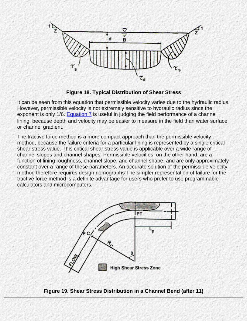
Figure 18. Typical Distribution of Shear Stress
It can be seen from this equation that permissible velocity varies due to the hydraulic radius.However, permissible velocity is not extremely sensitive to hydraulic radius since theexponent is only 1/6. Equation 7 is useful in judging the field performance of a channellining, because depth and velocity may be easier to measure in the field than water surfaceor channel gradient.
The tractive force method is a more compact approach than the permissible velocitymethod, because the failure criteria for a particular lining is represented by a single criticalshear stress value. This critical shear stress value is applicable over a wide range ofchannel slopes and channel shapes. Permissible velocities, on the other hand, are afunction of lining roughness, channel slope, and channel shape, and are only approximatelyconstant over a range of these parameters. An accurate solution of the permissible velocitymethod therefore requires design nomographs The simpler representation of failure for thetractive force method is a definite advantage for users who prefer to use programmablecalculators and microcomputers.
Figure 19. Shear Stress Distribution in a Channel Bend (after 11)

Design Parameters
Design Discharge Frequency
Design flow rates for permanent roadside and median drainage channel linings usually havea 5 or 10 year return period. A lower return period flow is allowable if a temporary lining is tobe used, typically the mean annual storm (approximately a 2-year return period, i.e., 50percent probability of occurrence in a year). Temporary channel linings are often usedduring the establishment of vegetation. The probability of damage during this relatively shorttime is low, and if the lining is damaged, repairs are easily made. Design procedures fordetermining the maximum permissible discharge in a roadway channel are given in Chapter4.
Channel Cross Section Geometry
Most highway drainage channels are trapezoidal or triangular in shape with roundedcorners. For design purposes, a trapezoidal or triangular representation is sufficient. Designof roadside channels should be integrated with the highway geometric and pavementdesign to insure proper consideration of safety and pavement drainage needs. If availablechannel linings are found to be inadequate for the selected channel geometry, it may befeasible to widen the channel. This can be accomplished by either increasing the bottomwidth or flattening the side slopes. Widening the channel will reduce the flow depth andlower the shear stress on the channel perimeter.
It has been demonstrated that if a riprap-lined channel has 1V:3H or flatter side slopes,there is no need to check the banks for erosion. (8) With steeper side slopes, a combinationof shear stress against the bank and the weight of the lining may cause erosion on thebanks before the channel bottom is disturbed. The design method in this manual includesprocedures for checking the adequacy of channels with steep side slopes.
Equations for determining cross-sectional area, wetted perimeter, and top width of channelgeometries commonly used for highway drainage channels are given in Appendix A.
Channel Slope
The channel bottom slope is generally dictated by the roadway profile and therefore isusually fixed. If channel stability conditions warrant and available linings are not sufficient, itmay be feasible to reduce the channel gradient slightly relative to the roadway profile. Forchannels outside the roadway right-of-way, The slope may be adjusted slightly.
Channel slope is one of the major parameters in determining shear stress. For a givendesign discharge, the shear stress in the channel with a mild or subcritical slope is smallerthan a channel with supercritical slope. Roadside channels with gradients in excess ofabout two percent will flow in a supercritical state. Most flexible lining materials are suitablefor protecting channel gradients of up to 10 percent. Riprap and wire-enclosed riprap aremore suitable for protecting very steep channels with gradients in excess of 10 percent.

Go to Chapter 4

Chapter 4 : HEC 15Design Procedure
Go to Chapter 5
Design Procedure
This section outlines the design procedure for flexible channel linings. Channels with steep gradients (slopes greater than 10%)will usually produce a tractive force in excess of the permissible shear stress for most linings presented in this chapter atrelatively small discharges. Also, when riprap is used on steeper gradients, the design procedure must take into consideration theadditional forces acting on the riprap. Designs involving riprap should be checked and compared to results obtained from designprocedures presented in Chapter 5. Steep Gradient Design. The more conservative results, i.e., largest riprap size, should beused for design. Other linings presented in this chapter are applicable over a wide range of channel gradients, provided thepermissible shear for the lining is not exceeded.
The basic design procedure is supplemented for riprap lined channels with side slopes steeper than 1V:3H. Use of side slopessteeper than 1V:3H is not encouraged for flexible linings other than riprap or gabions because of the potential for erosion of theside slopes. If a combination of linings is used, the composite channel lining procedure outlined in Chapter 6 should be used. Incases where flexible linings discussed in this circular do not provide adequate protection, other alternatives, including rigid liningsshould be considered. Because of the substantial increased cost of rigid linings, and their vulnerability to failure, otheralternatives such as use of additional inlets, a modified channel geometry or a flatter channel gradient are preferred.
Flexible Lining Design
The basic design procedure for flexible channel linings is quite simple. It involves only two computations and severalstraight forward comparisons of lining performance. The computations include a determination of the uniform flowdepth in the channel, known as the normal depth, and determination of the shear stress at maximum flow depth.Designers familiar with methods for determining normal depth may use any convenient method and the Manning'sroughness coefficients provided in this manual. A nomograph is also provided in this chapter for determining thenormal depth in trapezoidal channels. The computation for shear stress is much simpler and can be carried outwithout the need of any design aids.
The basic comparison required in the design procedure is that of permissible to computed shear stress for a lining. Atable and two figures are provided that give permissible shear stress values for a variety of lining types. If the

permissible shear stress is greater than the computed shear, the lining is considered acceptable. If a lining isunacceptable, a lining with a higher permissible shear stress is selected and the calculations for normal depth andshear stress is repeated. A worksheet is provided at the end of this chapter (Figure 23) for carrying out the designprocedures presented in this chapter.
Channels lined with gravel or riprap on side slopes steeper than 1V:3H must be designed using the steep side slopedesign procedure. Steep side slopes are allowable within a channel if cohesive soil conditions exist. Channels withsteep slopes should not be allowed if the channel is constructed in non-cohesive soils.
Permissible Shear Stress
The permissible shear stress, τp, indicates the force required to initiate movement of the lining material. Prior tomovement of the lining, the underlying soil is relatively protected. Therefore permissible shear stress is notsignificantly affected by the erodibility of the underlying soil. However, if the lining is eroded and moved, the bedmaterial is exposed to the erosive force of the flow. The consequence of lining failure on highly erodible soils is great,since the erosion rate after failure is high compared to soils of low erodibility.
Values for permissible shear stress for linings are based on research conducted at laboratory facilities and in thefield. The values presented here are judged to be conservative and appropriate for design use. Table 2 presentspermissible shear stress values for manufactured, vegetative, and riprap lining types. The permissible shear stress fornon-cohesive soils is a function of mean diameter of the channel material as shown in Chart 1. For larger stone sizesnot shown in Chart 1 and rock riprap, the permissible shear tress is given by the following equation:
p =628.3 D50
where:
D50 is the mean riprap size in meters
(8)
For cohesive materials the variation in permissible shear stress is governed by many soil properties. The plasticityindex of the cohesive soil provides a good guide to the permissible shear stress as shown in Chart 2.

Determination of Normal Flow Depth
The condition of uniform flow in a channel at a known discharge is computed using the Manning's equation combinedwith the continuity equation:
Where:
Q = dischargen = Manning's roughness coefficientA = cross-sectional areaR = hydraulic radiusSf = friction gradient which, for uniform flow conditions, equals thechannel bed gradient, S.
(9)
Chart 3 provides a solution to Manning's equation for trapezoidal channels. The geometric properties of a trapezoidalchannel can be found using Chart 4 or the equations provided in Appendix A.
Manning's Roughness Coefficients for Non-Vegetative Linings
Table 3 gives recommended values of the Manning's roughness coefficient for flexible channel lining materials,including riprap-type lining materials. The n values will vary with flow depth. The channel roughness will be higher forshallow flow depths and lower for large flow depths. The range of flow depths from 150 mm to 600 mm is typical ofhighway drainage channels should be used in most cases.
Manning's Roughness Coefficients for Vegetative Linings
Manning's roughness coefficient for vegetative linings varies significantly depending on the amount of submergenceof the vegetation and the flow force exerted on the channel bed. As a result, the Manning's n value must bedetermined by trial and error taking into consideration both the depth of flow and the flow force. Chart 5, Chart 6,Chart 7, Chart 8, and Chart 9 show the variation in Manning's n for five classes of vegetation. These charts can beused to determine Manning's n for a wide range of flow conditions.

Determination of Shear Stress on Channel
As presented in Chapter 3, Tractive Force Theory, the shear stress on the channel lining at maximum depth, τd, iscomputed using the following equation:
Equation 5 from Chapter 3
τd = γds
where:
γ = unit weight of water (9810 N/m3 )d = flow depth mS = channel gradient, m/m
Flow around a channel bend imposes higher shear stress on the channel bottom and banks. For bends, themaximum shear stress is given by the following equation:
Equation 6 from Chapter 3
τb =Kb τd
where:
the value of Kb can be found using Chart 10.
In Chart 10, the radius of curvature of the channel center line, RC, and the bottom width of the channel, B. determinethe magnitude of factor Kb. The length of protection, Lp, required downstream of a bend is found using Chart 11. Thelength of protection is a function of the roughness of the lining material in the bend (nb) and the depth of flow.
Side Slope Stability
Channels lined with gravel or riprap on side slopes steeper than 1V:3H may become unstable. As the angle of theside slopes approaches the angle of repose of the channel lining, the lining material becomes less stable. However,the shear stress on the channel side is less than the maximum shear stress occurring on the channel bed. Thestability of a side slope is a function of the channel side slope and the angle of repose of the rock lining material.
When the tractive force ratio is compared to the ratio of the shear stress on the sides to the shear stress on the

bottom of the channel, the rock size for the channel side slope can be determined. The angle of repose, θ. fordifferent rock shapes and sizes is provided in Chart 12. The ratio of shear stress on the sides and bottom of atrapezoidal channel, K1, is given in Chart 13 and the tractive force ratio, K2, is given in Chart 14. The required rocksize (mean diameter of the gradation D50) for the side slopes is found using the following equation:
equation 10
(10)
Maximum Discharge Approach
In many cases, the designer simply needs to know the maximum discharge a channel can convey given thepermissible shear stress and the corresponding allowable depth. By knowing the maximum discharge that a liningcan sustain, the designer can determine the maximum length of lining for a channel, based on the hydrology of thesite. This information can assist the designer in an economic evaluation of lining types and can determine inletspacing.
The procedure presented is for both vegetative linings and non-vegetative linings. Applying the procedure forvegetative linings is particularly useful, since it does not involve a trial and error solution.
Design Considerations for Riprap Lining
Two additional design considerations are required for riprap channel linings:Riprap gradation and thickness1.
Use of filter material under rock riprap.2.
Riprap Gradation and Thickness
Riprap gradation should follow a smooth size distribution curve. Most riprap gradations will fall in therange of D100 /D50 and D50 /D20 between 3.0 to 1.5, which is acceptable. The most important criterion is aproper distribution of sizes in the gradation so that interstices formed by larger stones are filled with

smaller sizes in an interlocking fashion, preventing the formation of open pockets. These gradationrequirements apply regardless of the type of filter design used.
In general, riprap constructed with angular stones has the best performance. Round stones areacceptable as riprap provided they are not placed on side slopes steeper than 1V:3H. Flat slab-like stonesshould be avoided since they are easily dislodged by the flow. An approximate guide to stone shape isthat neither the breadth nor thickness of a single stone is less than one-third its length.
The thickness of a riprap lining should equal the diameter of the largest rock size in the gradation. Formost gradations, this will mean a thickness from 1.5 to 3.0 times the mean riprap diameter.
Filter Design
When rock riprap is used, the need for an underlying filter material must be evaluated. The filter materialmay be either a granular filter blanket or a engineering fabric.
For a granular filter blanket , the following criteria must be met:
(11)
(12)
In the above relationships, "filter" refers to the overlying material and "base" refers to the underlyingmaterial. The relationships must hold between the filter blanket and base material and between the riprapand filter blanket .
The thickness of the granular filter blanket should approximate the maximum size in the filter gradation.The minimum thickness for a filter blanket should not be less than 150 mm.
In selecting an engineering filter fabric, the fabric should be able to transmit water from the soil and alsohave a pore structure that will hold back soil. The following properties of an engineering filter fabric arerequired to assure that their performance is adequate as a filter under riprap. (18)
The fabric must be able to transmit water faster than the soil.1.
The following criteria for the apparent opening size (AOS) must be met:2.
For soil with less than 50 percent of the particles by weight passing a U.S. No. 200sieve, AOS < 0.6 mm (greater than #30 U.S. Std. Sieve).
.
For soil with more than 50 percent of the particles by weight passing a U.S. No. 200sieve, AOS < 0.297 mm (greater that #50 U.S. Std. Sieve).
b.
The above criteria only applies to non-severe or non-critical installations. Severe or critical installationsshould be designed based on permeability tests.
Design Procedure
The design procedure is summarized below. The procedure for flexible linings is a basic stepwise solution approach.
Flexible Lining Design Procedure
(see computation sheet, Figure 23)
Step 1 . Select a flexible lining and determine the permissible shear stress, τp (see Table 2)
Step 2. Estimate flow depth for vegetation or flow depth range for linings, the channel shape, slope and designdischarge(s) .
Step 3 . Determine Manning's n value for estimated flow depth.For non-vegetative linings, use Table 3.
For vegetation: b.

Calculate the hydraulic radius, R. (Use Chart 4 for trapezoidal channels and Appendix A for othershapes.)
1.
Determine n from Chart 5, Chart 6, Chart 7, Chart 8, or Chart 9.2.
Step 4. Calculate the flow depth, d, in the channel. (Chart 3 for trapezoidal channels.)
Step 5 . Compare computed flow depth, d, with estimated flow depth, di. If d is outside the assumed range fornon-vegetative linings or differs by more than 0.030 m from di for vegetation, repeat steps 2 through 4.
Step 6. Calculate the shear stress, τd. If τd > τp, the lining is not acceptable, repeat steps 1 through 5.
τd = γdS .
Step 7. For channel bends:Determine the factor for maximum shear stress on channel bends, Kb, from Chart 10. This is a function of theratio of channel curvature to bottom width, Rc/B.
.
Calculate the shear stress in the bend, τb.b.
τb =Kbτd
If τb > τp, the lining is not acceptable, repeat steps 1 through 7.
(6)
(3)
Calculate length of protection, Lp, downstream of the bend from Chart 11.c.
Calculate superelevation. 4.
Step 8. For riprap or gravel linings on steep side slopes (steeper than 1V:3H):Determine the angle of repose for the rock size and shape from Chart 12..
Determine K1, the ratio of maximum side shear to maximum bottom shear for a trapezoidal channel from Chart13.
b.
Determine K1, the tractive force ratio from Chart 14. c.
Calculate the required D50 for the side slopes.4.

(10)
Step 9. For riprap on slopes greater than 10% check design procedure in Chapter 5. Use whichever procedureresults in the larger riprap size.
Maximum Discharge Design Procedure
Step 1. Determine the allowable depth of flow in the channel using the permissible shear stress (Table 2 or Chart 1 or Chart2). Check that this depth does not exceed the depth (including freeboard) provided in the typical roadway section.
(13)
Step 2. Determine the area and hydraulic radius corresponding to the allowable depth using Chart 4.
Step 3. For non-vegetative linings, find the correct Manning's n from Table 3.For vegetative linings, enter into Chart 5, Chart 6, Chart 7, Chart 8, and Chart 9 for the correct vegetation class and determinethe Manning's n value.
Step 4. Solve Manning's equation(equation 9) to determine the maximum discharge for the channel.
Example Problems

Example #1
Determine whether it is feasible to use jute net as a temporary lining.
Given: Q = 0.566 m3/s S = 0.005 m/m Trapezoidal channel with a bottom width of 1.22 m and 1V:3H side slopes.
Find: Depth of flow in the channel and the adequacy of the jute net lining
Solution:
1. From Table 2, the permissible shear stress is 21.5 N/m2 and from Table 3, the Manning's n value is 0.022(assuming a flow depth between 0.15 to 0.60 m).
2. Entering Chart 3 for S=0.005 Qn=0.012 B=1.22 d/B=0.22 d=0.268 m
The flow depth has remained within the range of 0.15 to 0.60 m so that the assumed Manning's n value iscorrect.
3. Using equation 5, the shear stress on the channel bed at maximum depth is,τd = γds = 9810 x 0.268 x 0.005 = 13.1 N/m2
4. Comparing the shear stress, 13.1 N/m2, to the permissible shear stress, 21.5 N/m2 shows that jute net is anacceptable channel lining.
Example #2
Determine if a single application of fiberglass roving lining is an adequate lining for a median ditch.
Given: B = 0.61 m Z = 4 S = 0.05 m/m Q = 0.283 m3/s

Find: Depth of flow .
Solution:
1. From Table 3, Manning's n is 0.021 assuming a flow depth in the range of 0.15 to 0.60 m
2. Entering Chart 3 for S = 0.05, given Qn = 0.0059 m3/s B = 0.61 d/B = 0.21 d = 0.128 m
Checking the flow depth against the initial assumed range shows that the computed depth is below that range. TheManning's n for flow depth range of 0.0 to 0.15 m is 0.028.
Enter Chart 3 for S=0.05 Qn = 0.007 m3/s B = 0.61 d/B = 0.24 d = 0.146 m
The computed flow depth is within the assumed range.
3.The maximum shear stress from equation 5 is,
τd = γds = 9810 x 0.146 x 0.05 = 71.6 N/m2
4. The permissible shear stress for fiberglass is 28.7 N/m2. Since this is less than the maximum shear stress, thelining is not adequate.
Example #3
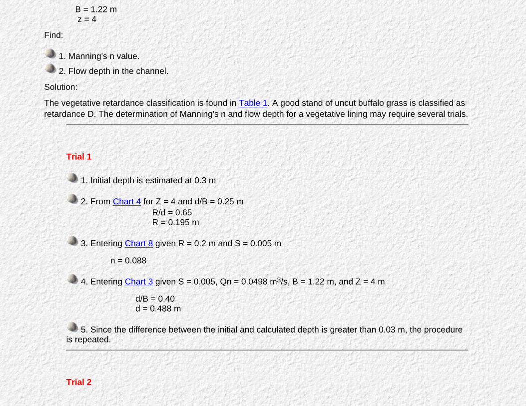
A roadside ditch is lined with a good stand of uncut buffalo grass. Determine the flow depth and Manning's n for thedepth at design discharge.
Given: Q = 0.566m3/s S = 0.005 m/m
B = 1.22 m z = 4
Find:
1. Manning's n value.
2. Flow depth in the channel.
Solution:
The vegetative retardance classification is found in Table 1. A good stand of uncut buffalo grass is classified asretardance D. The determination of Manning's n and flow depth for a vegetative lining may require several trials.
Trial 1
1. Initial depth is estimated at 0.3 m
2. From Chart 4 for Z = 4 and d/B = 0.25 m R/d = 0.65 R = 0.195 m
3. Entering Chart 8 given R = 0.2 m and S = 0.005 m
n = 0.088
4. Entering Chart 3 given S = 0.005, Qn = 0.0498 m3/s, B = 1.22 m, and Z = 4 m
d/B = 0.40 d = 0.488 m
5. Since the difference between the initial and calculated depth is greater than 0.03 m, the procedureis repeated.
Trial 2

1.Use the calculated depth of 0.488 m from trial 1.
2. From Chart 4 for Z = 4 and d/B = 0.40 R/d = 0.61 R = 0.298 m
3. Entering Chart 8 given R = 0.298 m and S = 0.005 m,
n = 0.066
4. Entering Chart 3 given S = 0.005 Qn = 0.0374 B =1.22 m
d/B = 0.36 d = 0.439 m
5. Since the difference between the initial and calculated depths is 0.049 m which is greater than 0.03m the procedure is repeated.
Trial 3
1. Use the calculated depth of 0.439 m from trial 2.
2. From Chart 4 for Z = 4 and d/B = 0.36 R/d = 0.61 R = 0.268 m
3. Entering Chart 8 given R = 0.268 m and S = 0.005 m,
n = 0.070
4. Entering Chart 3 given S = 0.004, Qn =0.0396 m3/s, and B =1.22,
d/B = 0.37 d = 0.45 m
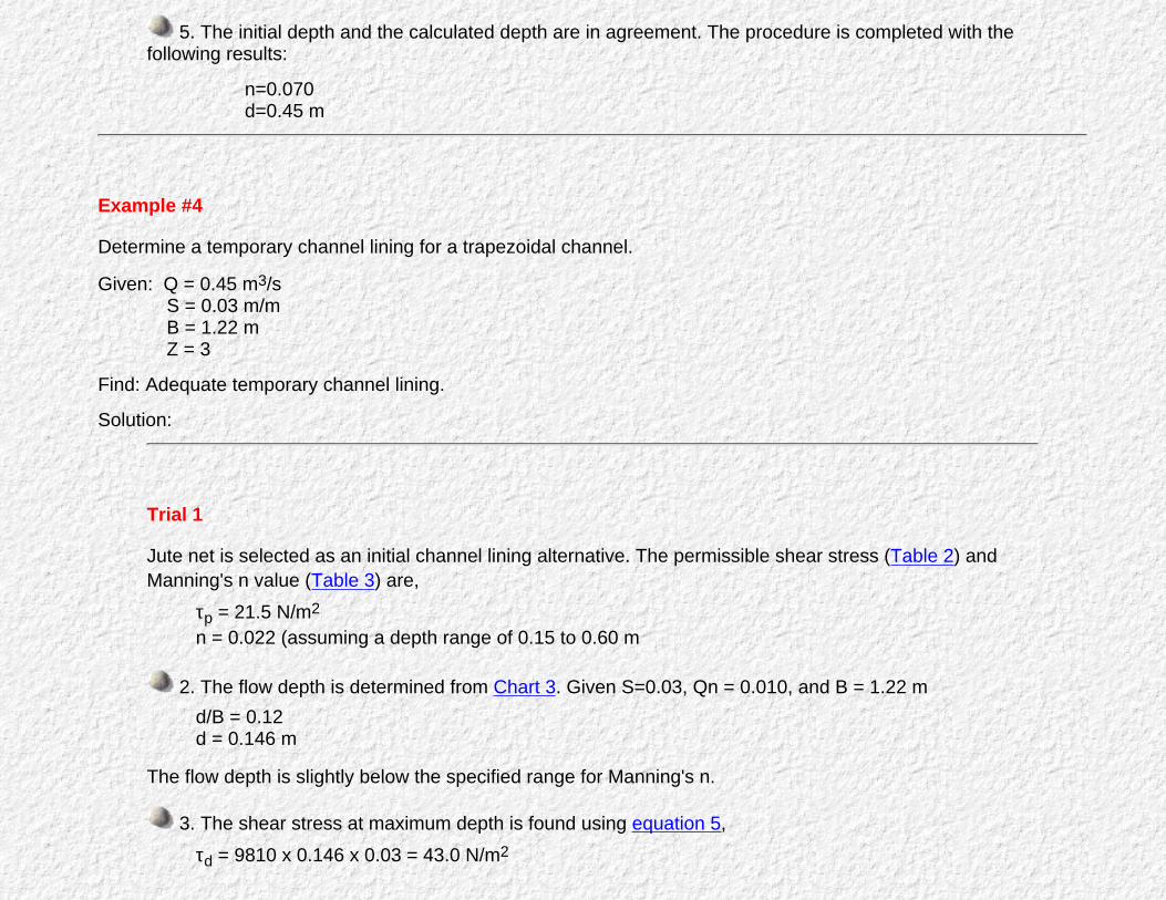
5. The initial depth and the calculated depth are in agreement. The procedure is completed with thefollowing results:
n=0.070d=0.45 m
Example #4
Determine a temporary channel lining for a trapezoidal channel.
Given: Q = 0.45 m3/s S = 0.03 m/m B = 1.22 m Z = 3
Find: Adequate temporary channel lining.
Solution:
Trial 1
Jute net is selected as an initial channel lining alternative. The permissible shear stress (Table 2) andManning's n value (Table 3) are,
τp = 21.5 N/m2
n = 0.022 (assuming a depth range of 0.15 to 0.60 m
2. The flow depth is determined from Chart 3. Given S=0.03, Qn = 0.010, and B = 1.22 md/B = 0.12d = 0.146 m
The flow depth is slightly below the specified range for Manning's n.
3. The shear stress at maximum depth is found using equation 5,τd = 9810 x 0.146 x 0.03 = 43.0 N/m2
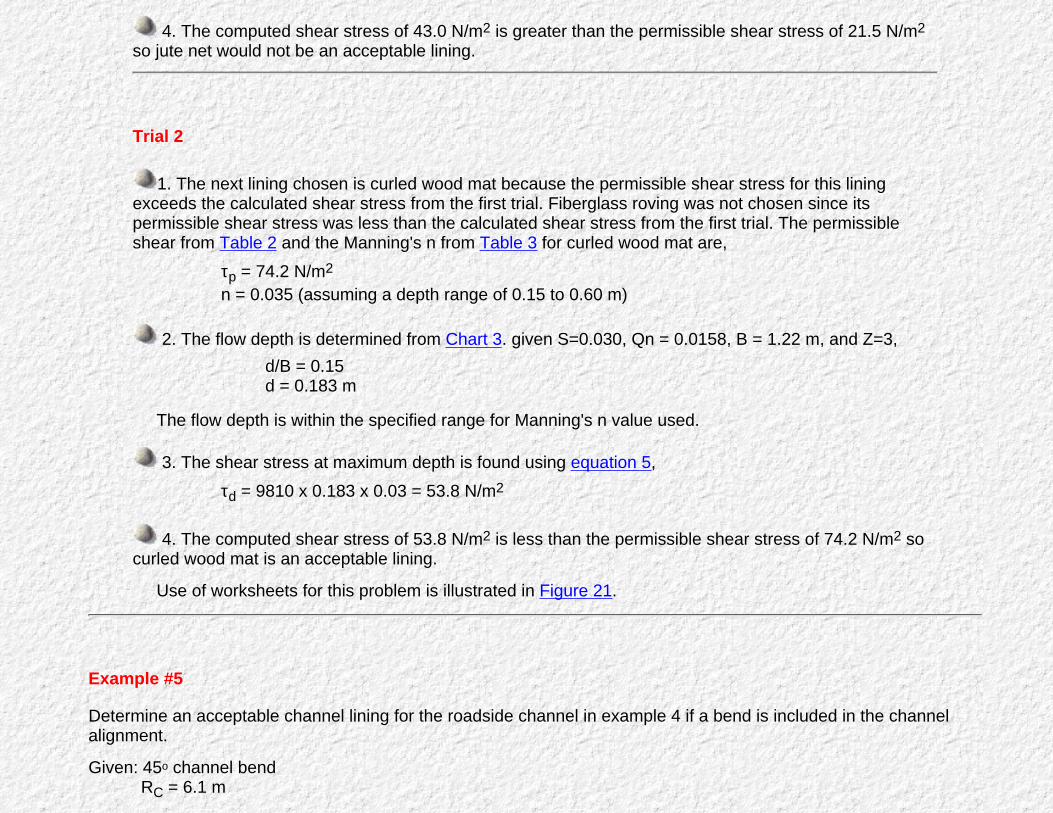
4. The computed shear stress of 43.0 N/m2 is greater than the permissible shear stress of 21.5 N/m2
so jute net would not be an acceptable lining.
Trial 2
1. The next lining chosen is curled wood mat because the permissible shear stress for this liningexceeds the calculated shear stress from the first trial. Fiberglass roving was not chosen since itspermissible shear stress was less than the calculated shear stress from the first trial. The permissibleshear from Table 2 and the Manning's n from Table 3 for curled wood mat are,
τp = 74.2 N/m2
n = 0.035 (assuming a depth range of 0.15 to 0.60 m)
2. The flow depth is determined from Chart 3. given S=0.030, Qn = 0.0158, B = 1.22 m, and Z=3,d/B = 0.15d = 0.183 m
The flow depth is within the specified range for Manning's n value used.
3. The shear stress at maximum depth is found using equation 5,τd = 9810 x 0.183 x 0.03 = 53.8 N/m2
4. The computed shear stress of 53.8 N/m2 is less than the permissible shear stress of 74.2 N/m2 socurled wood mat is an acceptable lining.
Use of worksheets for this problem is illustrated in Figure 21.
Example #5
Determine an acceptable channel lining for the roadside channel in example 4 if a bend is included in the channelalignment.
Given: 45o channel bend RC = 6.1 m

Find:
1. The channel lining required for the bend and the location of the lining.
2. The superelevation of the water surface in the bend.
Solution :
Trial 1
1. From the results of example 4, the shear stress of the straight reach upstream of the bend is,τd = 53.8 N/m2
A curled wood mat lining was used to stabilize the channel.
2. The shear stress in the bend is given by equation 6. The value of Kb in equation 6 is found fromChart 10 given RC/B = 5,
Kb = 1.6
The bend shear stress is,τb = 1.6 x 53.8 = 86.1 N/m2
3. The computed shear stress in the bend is greater than the permissible shear stress for a curledwood mat channel lining (74.2 N/m2). A new lining is required for the channel bend.
Trial 2
1. Synthetic mat is chosen as a bend lining material, because its permissible shear stress from Table 2(95.8 N/m2) is greater than the computed shear stress from trial 1. The Manning's n value is 0.025 for aflow depth range from 0.15 to 0.60 m.
2. Entering Chart 3 given S = 0.03, Qn = 0.011, and B = 1.22 m
d/B = 0.13d = 0.159 m
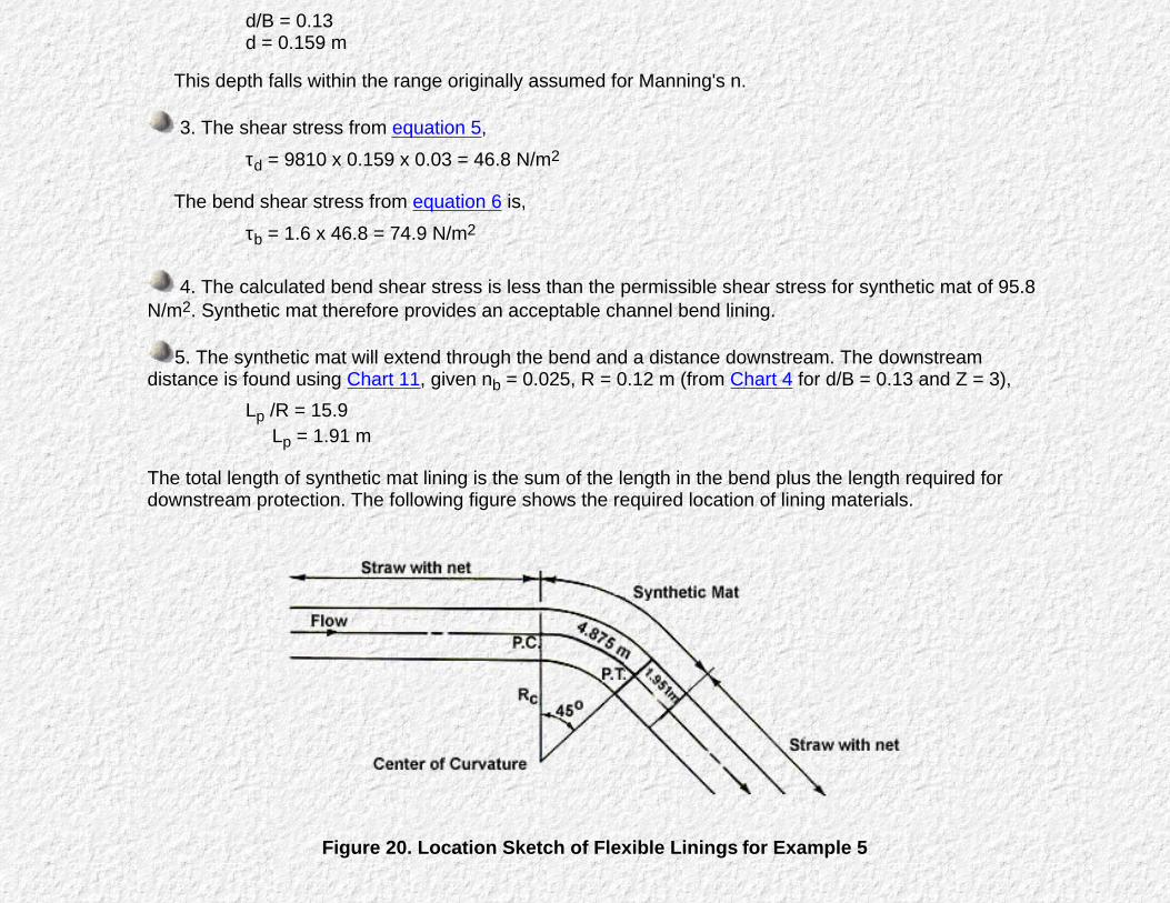
This depth falls within the range originally assumed for Manning's n.
3. The shear stress from equation 5,τd = 9810 x 0.159 x 0.03 = 46.8 N/m2
The bend shear stress from equation 6 is,τb = 1.6 x 46.8 = 74.9 N/m2
4. The calculated bend shear stress is less than the permissible shear stress for synthetic mat of 95.8N/m2. Synthetic mat therefore provides an acceptable channel bend lining.
5. The synthetic mat will extend through the bend and a distance downstream. The downstreamdistance is found using Chart 11, given nb = 0.025, R = 0.12 m (from Chart 4 for d/B = 0.13 and Z = 3),
Lp /R = 15.9 Lp = 1.91 m
The total length of synthetic mat lining is the sum of the length in the bend plus the length required fordownstream protection. The following figure shows the required location of lining materials.
Figure 20. Location Sketch of Flexible Linings for Example 5

6. The superelevation of the water surface is computed from equation 3. To execute equation 3, topwidth and cross-sectional area must be computed, where,
T = B + 2Zd = 1.22 + 2 x 3 x 0.158 = 2.16 m
andA = Bd + Zd2 = 1.22 x 0.158 + 3 x 0.1582 = 0.268 m2
The velocity in the channel found using the continuity equation(equation 2),
V = Q/A = 0.45/0.268 = 1.68 m/s
Solving equation 3 given V = 1.68 m/s, T = 2.16 m, and Rc=6.1m
The freeboard in the channel bend should be at least 0.10 meters to accommodate the super elevation ofthe water surface.
Use of the worksheets for this problem is illustrated in Figure 21.
Example #6
Because of a width constraint on available right-of-way, the side slopes of a roadside ditch must be steepened to1V:2H. The 51-mm gravel lining has been determined to be adequate to protect the ditch bed. Determine the gravelsize, D50, necessary to protect the ditch banks.
Given: Very rounded gravel A trapezoidal channel.
Z = 2
B = 1.07 m
Flow depth, d = 0.213 m
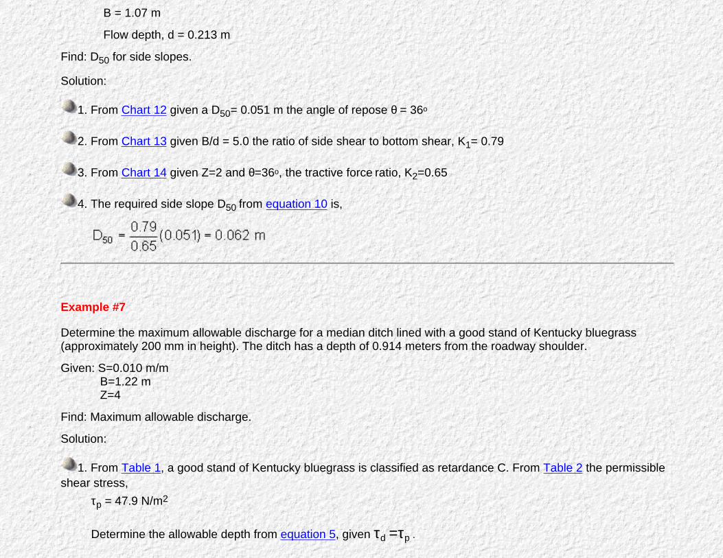
Find: D50 for side slopes.
Solution:
1. From Chart 12 given a D50= 0.051 m the angle of repose θ = 36o
2. From Chart 13 given B/d = 5.0 the ratio of side shear to bottom shear, K1= 0.79
3. From Chart 14 given Z=2 and θ=36o, the tractive force ratio, K2=0.65
4. The required side slope D50 from equation 10 is,
Example #7
Determine the maximum allowable discharge for a median ditch lined with a good stand of Kentucky bluegrass(approximately 200 mm in height). The ditch has a depth of 0.914 meters from the roadway shoulder.
Given: S=0.010 m/m B=1.22 m Z=4
Find: Maximum allowable discharge.
Solution:
1. From Table 1, a good stand of Kentucky bluegrass is classified as retardance C. From Table 2 the permissibleshear stress,
τp = 47.9 N/m2
Determine the allowable depth from equation 5, given τd =τp .

d = τp/γS = 47.9 = 0.488 m 9810 x 0.01
Note: The allowable depth is less than the depth of the ditch.
2. Determine the flow area and hydraulic radius from Chart 4, given d/B = 0.40,A/Bd = 2.6A = 1.55 m2
R/d = 0.61R = 0.3 m
3. From Chart 7: n=0.072.
4. Solving the Manning's equation with continuity equation (equation 9),Q= 1 AR2/3 S1/2 = 1 x 1.55 x 0.32/3 x 0.011/2 = 0.96 m3/s n 0.072

Figure 21. Worksheet for Example Problems 4 and 5
Example #8
Determine the need for a granular filter blanket.
Given: Riprap GradationD85 =0.40 mD50 =0.20 mD15 =0.10 m
Base Soil Gradation
D85 =1.5 mm=0.0049 ftD50 = 0.5 mm=0.0016 ftD15 =0.167mm=0.00055 ft
Find: Granular Filter Blanket Requirement.
Solution:
Since the relationship between riprap and base do not meet the recommended dimensional criteria, a filter blanket isrequired. First, determine the required dimensions of the filter with respect to the base material.D50 filter < 40, so D50 filter < 40 x 0.5 mm = 20 mmD50 baseD15 filter < 40, so D15 filter < 40 x 0.167 mm = 6.7 mmD15 baseD15 filter < 5, so D15 filter < 5 x 1.5 mm = 7.3 mmD85 baseD15 filter > 5, so D15 filter > 5 x 0.167 mm = 0.84 mmD15 base
Therefore, with respect to the base material, the filter must satisfy:D50 filter < 20 m
0.84 m <D15 filter < 6.7 mm
Second, determine the required filter dimensions with respect to the riprap,D 50 riprap< 40, So , D50 filter >0.20= 5.0 mD50 filter 40D 15 riprap< 40, So , D15 filter >0.10= 2.5 mmD15 filter 40D 15 riprap 0.10
< 5, So , D85 filter > = 20 mmD85 filter 5D 15 riprap> 5, So , D15 filter > 0.10= 20 mmD15 filter 5With respect to the riprap:
D50 filter > 5.0 mm2.5 mm < D15 filter < 20.0 mm D85 filter > 20.0 mm
Combining:
2.5 mm < D15 filter < 6.7 mm5.0 mm < D50 filter < 20.0 mm D85 filter > 20.0 mm
The gradation requirements for the resulting granular filter blanket specifications are illustrated in Figure 22.
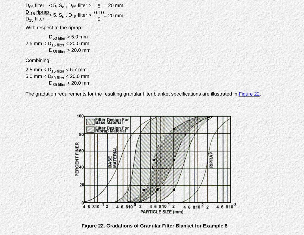
Figure 22. Gradations of Granular Filter Blanket for Example 8
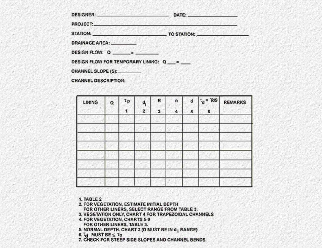

Figure 23. Worksheet for Flexible Lining
Click on a hyperlinks below to view the following tables:
Table 1. Classification of Vegetal Covers as to Degree of RetardanceTable 2. Permissible Shear Stresses for Lining MaterialTable 3. Manning's Roughness Coefficients

Chart 1. Permissible Shear Stress for Non-Cohesive Soils (after 15)
Chart 2. Permissible Shear Stress for Cohesive Soils (after 16)


Chart 3. Solution of Manning's Equation for Channels of Various Side Slopes (after 17)
Chart 4. Geometric Design Chart for Trapezoidal Channels

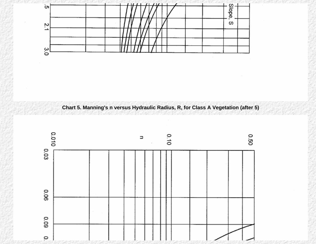
Chart 5. Manning's n versus Hydraulic Radius, R, for Class A Vegetation (after 5)

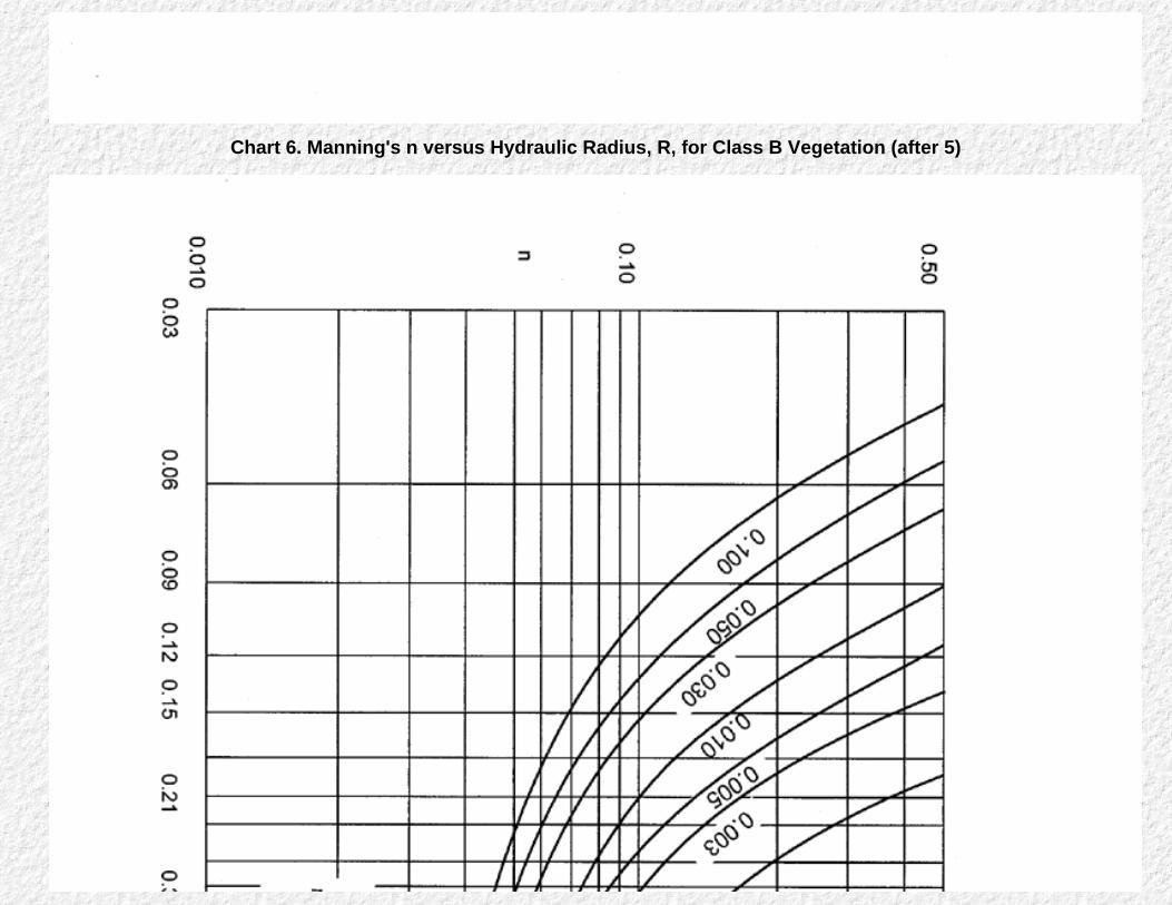
Chart 6. Manning's n versus Hydraulic Radius, R, for Class B Vegetation (after 5)

Chart 7. Manning's n versus Hydraulic Radius, R, for Class C Vegetation (after 5)
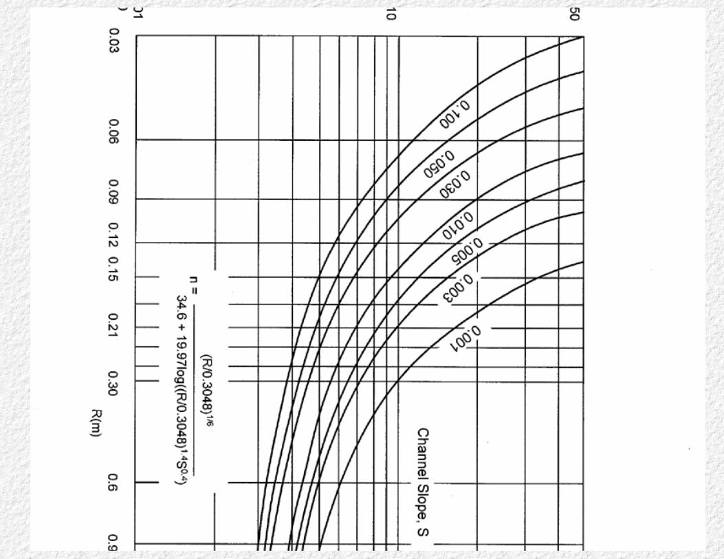
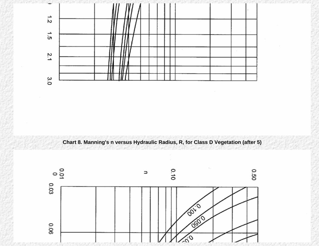
Chart 8. Manning's n versus Hydraulic Radius, R, for Class D Vegetation (after 5)

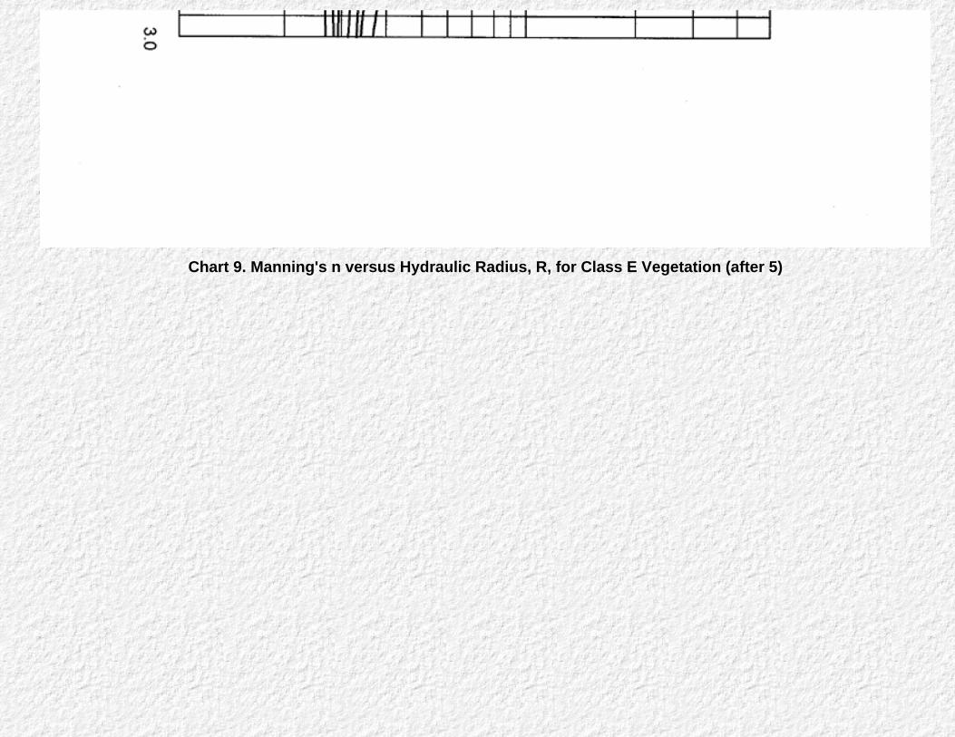
Chart 9. Manning's n versus Hydraulic Radius, R, for Class E Vegetation (after 5)
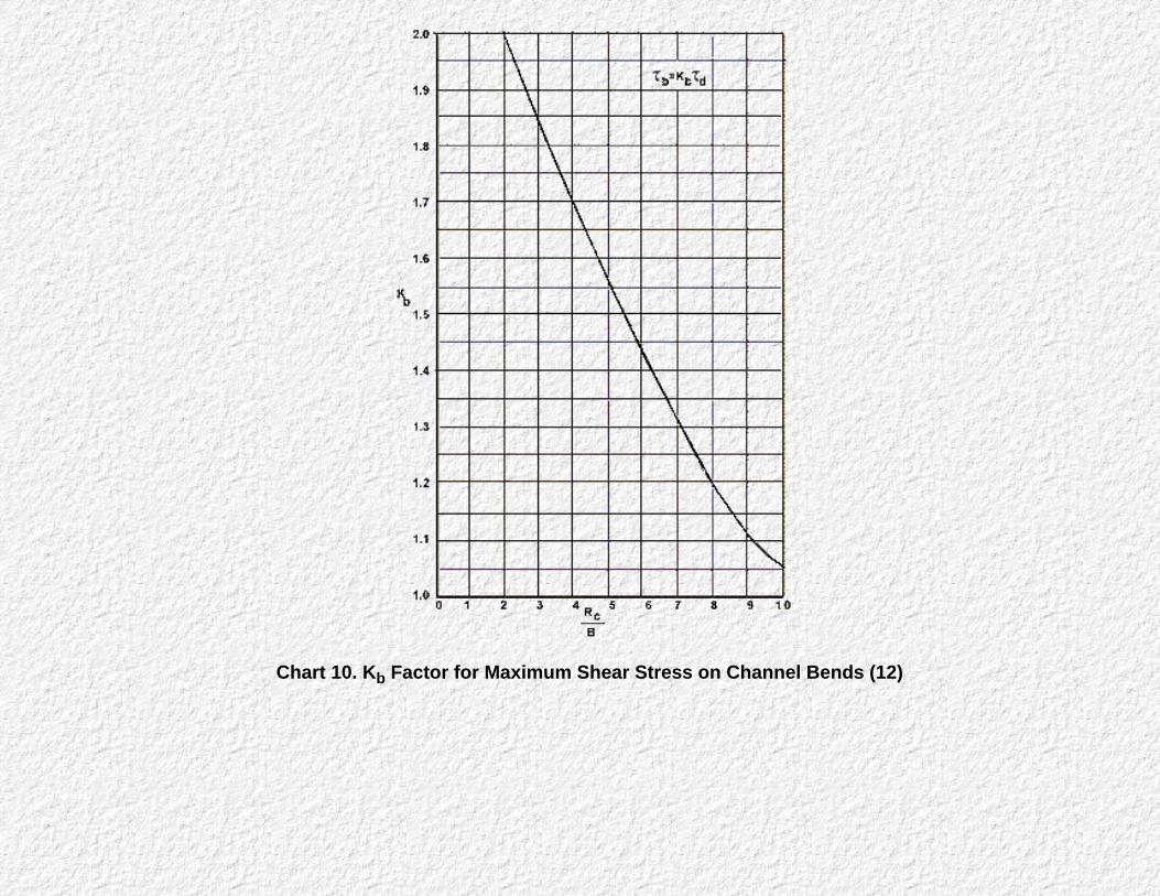
Chart 10. Kb Factor for Maximum Shear Stress on Channel Bends (12)

Chart 11. Protection Length, Lp, Downstream of Channel Bend

Chart 12. Angle of Repose Riprap in Terms of Mean Size and Shape of Stone

Chart 13. Channel Side Shear Stress to Bottom Shear Stress Ratio, K1 (8)
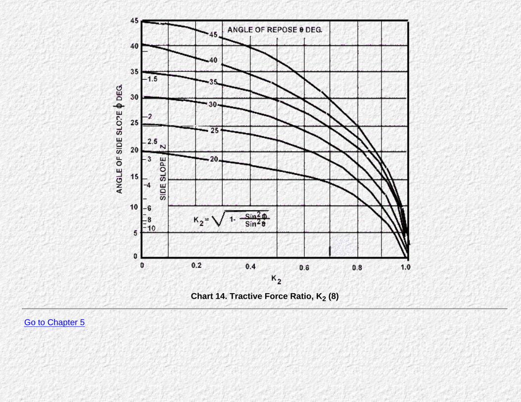
Chart 14. Tractive Force Ratio, K2 (8)
Go to Chapter 5
Chapter 5 : HEC 15Steep Gradient Channel Design
Go to Chapter 6
Steep Gradient Channel Design
Achieving channel stability on steep gradients usually requires some type of channel lining except where the channels can beconstructed in durable bedrock. This section outlines the design of two types of flexible channel linings for steep gradients, riprap,and gabion mattress. Because of the additional forces acting on riprap, results obtained using the previous design procedureshould be compared to the steep gradient procedures when channel gradients approach 10 percent.
Rigid channel linings may be a more cost-effective alternative in the case of steep slope conditions. The size of riprap and gabionlinings increases quickly as discharge and channel gradient increase. The decision to select a rigid or flexible lining may bebased on other site conditions, such as foundation and maintenance requirements for the steep slope channel lining.
Steep Slope Design
Riprap stability on a steep slope depends on forces acting on an individual stone making up the riprap. The primary forcesinclude the average weight of the stones and the lift and drag forces induced by the flow on the stones. On a steep slope, theweight of a stone has a significant component in the direction of flow (see figures in Appendix C). Because of this force, a stonewithin the riprap will tend to move in the flow direction more easily than the same size stone on a mild gradient. Hence, for agiven discharge, steep slope channels require larger stones to compensate for larger forces in the flow direction and higher shearstress. The riprap design procedure is based on the factor of safety method for riprap design, using a safety factor of 1.5. Adescription of the factor of safety method and the assumptions made in developing the design charts is presented in Appendix C.
Gabion mattress stability on a steep slope is similar to that of riprap but because the stones are bound by wire mesh, they tend toact as a single unit. Movement of stones within a gabion is negligible. This permits use of smaller stone sizes compared to thoserequired for loose riprap. Of course the stability of gabions depends on the integrity of the wire mesh. In streams with highsediment concentrations or with rocks moving along the bed of the channel, the wire mesh may be abraded and eventually fail.Under these conditions the gabion will no longer behave as a single unit but rather as individual stones. Applications of gabionmattresses and baskets under these conditions should be avoided. A worksheet is provided at the end of this chapter (Figure 25)for carrying out design procedures in this chapter.
Other Considerations for Steep Slope Design
Channel Alignment and Freeboard
Bends should be avoided on steep gradient channels. A design requiring a bend in a steep channelshould be reevaluated to eliminate the bend or designed using a culvert.
Extent of riprap or gabions on a steep gradient must be sufficient to protect transition regions of thechannel both above and below the steep gradient section. The transition from a steep gradient to a culvertshould allow for slight movement of riprap or slumping of a gabion mattress.
Riprap or gabions should be placed flush with the invert of a culvert. The break between the steep slopeand culvert entrance should equal three to five times the mean rock diameter (or mattress thickness ifgabions are used). The transition from a steep gradient channel to a mild gradient channel may require anenergy dissipation structure such as a plunge pool. The transition from a mild gradient to a steep gradientshould be protected against local scour upstream of the transition for a distance of approximately fivetimes the uniform depth of flow in the downstream channel.(7)
Freeboard should equal the mean depth of flow, since wave height will reach approximately twice themean depth. This freeboard height should be used for both temporary and permanent channelinstallations.
Gradation, Thickness, and Filter Requirements
Riprap gradation, thickness and filter requirements are the same as those for mild slopes. It is importantto note that riprap thickness is measured normal to steep channel gradients. Also, the rock gradation usedin gabions mattress must be such that larger stones do not protrude outside the mattress and smallerstones are retained by the wire mesh.
Design Procedures
A stepwise guideline with complete references to charts and figures is given for steep slope riprap and steep slopegabion mattress designs.
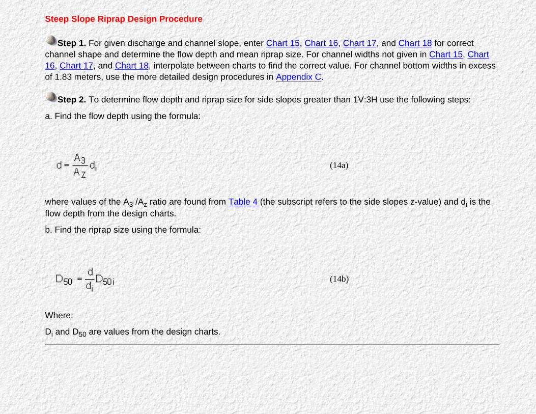
Steep Slope Riprap Design Procedure
Step 1. For given discharge and channel slope, enter Chart 15, Chart 16, Chart 17, and Chart 18 for correctchannel shape and determine the flow depth and mean riprap size. For channel widths not given in Chart 15, Chart16, Chart 17, and Chart 18, interpolate between charts to find the correct value. For channel bottom widths in excessof 1.83 meters, use the more detailed design procedures in Appendix C.
Step 2. To determine flow depth and riprap size for side slopes greater than 1V:3H use the following steps:
a. Find the flow depth using the formula:
(14a)
where values of the A3 /Az ratio are found from Table 4 (the subscript refers to the side slopes z-value) and di is theflow depth from the design charts.
b. Find the riprap size using the formula:
(14b)
Where:
Di and D50 are values from the design charts.

Steep Slope Gabion Mattress Design
Step 1. For given discharge and channel slope, enter Chart 19, Chart 20, Chart 21, and Chart 22 for correctchannel shape and determine flow depth. For intermediate channel widths or side slopes, follow the interpolationprocedures given in steep slope riprap design procedure. For channel bottom widths in excess of 1.8276 meters, seeAppendix C.
Step 2. Determine the permissible shear stress for the gabion mattress rock fill size from Chart 23.
Step 3. Determine the permissible shear stress for thickness of the gabion mattress from Chart 24.
Step 4. The design permissible shear stress, τp, will be the larger of the two shear stress values determined insteps 2 and 3.
Step 5. Calculate the maximum shear stress acting on the channel, τd.
τd = γdS (5)
If τd > τp, the gabion mattress analyzed is not acceptable.
Example Problems
Example #9
Determine the mean riprap size and flow depth for a steep gradient channel.
Given: Q = 0.566 m3/s. S = 0.15 m/m B = 0.61 m z = 3
Find: Flow depth and mean riprap size.
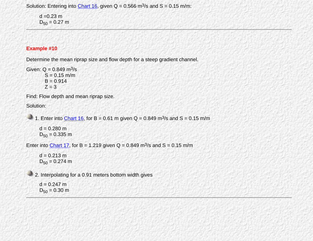
Solution: Entering into Chart 16, given Q = 0.566 m3/s and S = 0.15 m/m:
d =0.23 mD50 = 0.27 m
Example #10
Determine the mean riprap size and flow depth for a steep gradient channel.
Given: Q = 0.849 m3/s S = 0.15 m/m B = 0.914 Z = 3
Find: Flow depth and mean riprap size.
Solution:
1. Enter into Chart 16, for B = 0.61 m given Q = 0.849 m3/s and S = 0.15 m/m
d = 0.280 mD50 = 0.335 m
Enter into Chart 17, for B = 1.219 given Q = 0.849 m3/s and S = 0.15 m/m
d = 0.213 mD50 = 0.274 m
2. Interpolating for a 0.91 meters bottom width gives
d = 0.247 mD50 = 0.30 m

Example #11
Determine the mean riprap size and flow depth for a steep gradient channel.
Given: Q = 0.566 m3/s S = 0.20 m/m B = 0.61 m z = 4
Find: Flow depth and mean riprap size.
Solution:
1.Enter into Chart 16, given Q = 0.566 m3/s and S = 0.20 m/m,
d = 0.213 m
D50 = 0.36 m
2. Enter into Table 4, given d/B = 0.35 and Z = 4:
A3 /A4 = 0.85
Actual flow depth for 1V:4H side slopes,
d = 0.85 x 0.213 = 0.181 m
Actual riprap size for 1V:4H side slopes,
D50 = (0.181/0.213) x 0.36 = 0.31 m
Use of the worksheet for this problem is illustrated in Figure 24.
Example #12
Determine the flow depth and required thickness of a gabion mattress lining.
Given: Q = 0.283m3/s S = 0.12 m/m B = 0.61 m Z = 3

D50 = 0.15 m
Find: Flow depth and gabion mattress thickness.
Solution:
1. From Chart 20 given Q = 0.283 m3/sec. and S =0.12 m/m
d = 0.167 m
2. Calculate the maximum shear stress from equation 5,
τd = γdS = 1000 x 0.167 x 0.12 = 196.6 N/m2
3. Permissible shear stress for Rock-fill size from Chart 23,
τp = 181.9 N/m2
Permissible shear stress for a 0.23 meter mattress thickness from Chart 24,
τp = 215.5 N/m2
Use τp = 215.5 N/m2 for design.
4. The gabion mattress 0.23 meter thick is acceptable, since
τd = 196.6 < 215.5 = τp
Use of the worksheet for this problem is illustrated in Figure 24.
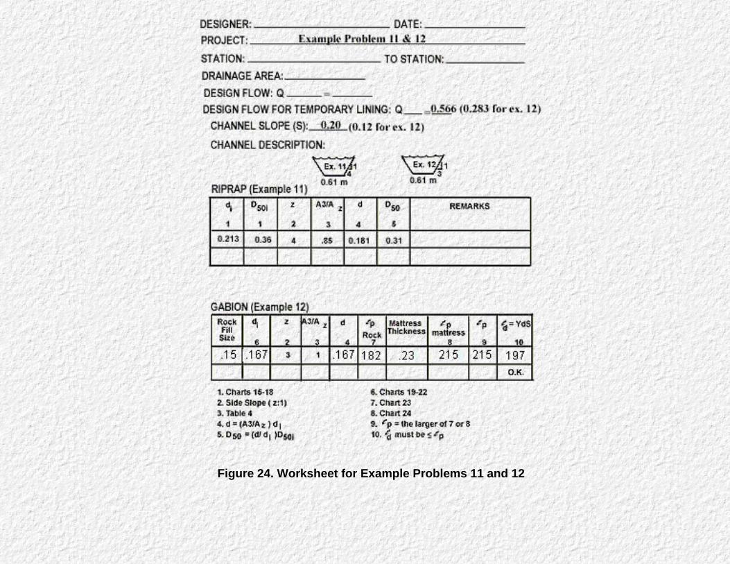
Figure 24. Worksheet for Example Problems 11 and 12

Figure 25. Worksheet for Steep Slope Channel Design
Table 4. Values of A3/Az for Selection Side Slope and Depth to Bottom Width Ratios1
d/B
A 3 /A z
1V:2H 1V:3H 1V:4H 1V:5H 1V:6H

0.100.200.300.400.500.600.700.800.901.001.101.201.301.401.501.601.701.801.902.00
1.0831.1421.1871.2221.2501.2721.2911.3071.3211.3331.3431.3521.3611.3681.3781.3811.3861.3911.3951.400
1.0001.0001.0001.0001.0001.0001.0001.0001.0001.0001.0001.0001.0001.0001.0001.0001.0001.0001.0001.000
0.9280.8880.8530.8460.8330.8230.8150.8090.8040.8000.7960.7930.7900.7870.7850.7830.7820.7800.7790.777
0.8660.8000.7600.7330.7140.7000.6880.6800.6720.6660.6610.6570.6530.6500.6470.6440.6420.6400.6380.636
0.8120.7270.6780.6470.6250.6080.5960.5860.5780.5710.5650.5610.5560.5530.5500.5470.5440.5420.5400.538
1based on the following equation:
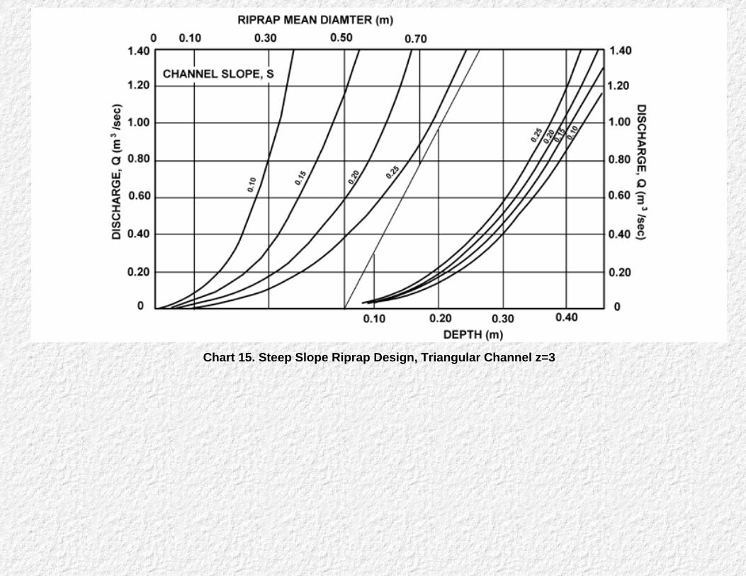
Chart 15. Steep Slope Riprap Design, Triangular Channel z=3

Chart 16. Steep Slope Riprap Design, B=0.6 m, Z=3

Chart 17. Steep Slope Riprap Design, B=1.2 m, Z=3
Chart 18. Steep Slope Riprap Design, B=1.8 m, Z=3

Chart 19. Steep Slope Gabion Mattress, Triangular Channel, Z=3

Chart 20. Steep Slope Gabion Mattress, B=0.6 m, Z=3
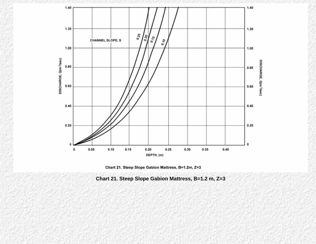
Chart 21. Steep Slope Gabion Mattress, B=1.2 m, Z=3

Chart 22. Steep Slope Gabion Mattress, B=1.8 m, Z=3

Chart 23. Permissible Shear Stress for Gabion Mattress versus Rock Fill Size

Chart 24. Permissible Shear Stress for Gabion Mattress versus Mattress Thickness
Go to Chapter 6
Chapter 6 : HEC 15Design Composite Lining
Go to Appendix A
Composite Lining Design
Composite linings protect the bed of a channel against the higher shear stress occurring in that portion of thechannel. The distribution of shear stress in a trapezoidal channel section (see Figure 18, Chapter 3) is such that themaximum shear stress on the sides of the channel is significantly less than on the channel bottom. This allows for achannel lining material to be used on the side slopes that has a lower permissible shear stress that the liningmaterial used for the bottom of the channel. The maximum shear on the side of the channel is given by the followingequation:
τs = K1 τ d
where:
K1 is a function of channel geometry and is given in Chart 13.τd is the shear stress at maximum depth.
(15)
It is important that the bed lining material cover the entire channel bottom so that adequate protection is provided.To guarantee that the channel bottom is completely protected, the bed lining should be extended a small distanceup the side slope.
Computation of flow conditions in a composite channel requires the use of an equivalent Manning's n value for theentire perimeter of the channel. For determination of equivalent roughness, the channel area is divided into twoparts of which the wetted perimeters and Manning's n values of the low- flow section and channel sides are known.These two areas of the channel are then assumed to have the same mean velocity. Chart 25 provides a means ofdetermining the equivalent roughness coefficient, KC, for various applications of two channel linings.
Another important use of composite linings are in vegetative lined channels that have frequent low flows. These lowflows will usually kill the submerged vegetation. In erodible soils, this leads to the formation of a small gully at thebottom of the channel. Gullies weaken a vegetative lining during higher flows, causing additional erosion, and canresult in a safety hazard. A solution is to provide a non-vegetative low-flow channel lining such as concrete orriprap. The dimensions of the low-flow channel are sufficient to carry frequent low flows but only a small portion ofthe design flow. The remainder of the channel is covered with vegetation.
Special Considerations
When two lining materials with significantly different roughness values are adjacent to each other, erosion mayoccur near the boundary of the two linings. Erosion of the weaker lining material may damage the lining as a whole.In the case of composite channel linings with vegetation on the banks, this problem can occur in the early stages ofvegetative establishment. A temporary lining should be used adjacent to the low-flow channel to provide erosionprotection until the vegetative lining is well established.
Design Procedure

Composite Lining Design Procedure
The procedure for composite linings designs consists of the following steps.
Step 1. Determine the permissible shear stress τp, for both lining types.(see Table 2)
Step 2. Estimate the depth of flow, di.
Step 3. Determine Manning's n for each lining type. (Table 3 for non-vegetative linings and Chart 5,Chart 6, Chart 7, Chart 8, and Chart 9 for vegetative linings.)
Step 4. Compute the ratio of rougher to smoother Manning's n values, n2/n1.
Step 5. Determine the hydraulic radius, R. and the wetted perimeter, P. for the entire channel section(Chart 4 or equations in Appendix A).
Step 6. Compute the ratio of low-flow channel wetted perimeter, , to total wetted perimeter, (
/P).
Step 7. Determine a compound lining factor, KC, from Chart 25. Calculate the effective Manning's nfrom,
n = KC n1
where:
n1 = Manning's n for smoother lining.
Step 8. Determine channel flow depth, d, using the effective Manning's n.
Step 9. Compare estimated flow depth, di, with calculated flow depth, d. If the difference is greaterthan 0.03 m repeat steps 3 through 8.
Step 10. Determine the shear stress at maximum depth, τd, and the shear stress on the channelside slope, τs
τd = γdS
and
τs = K1 τd (15)
Where K1 is from Chart 13.
Step 11. Compare the shear stresses, τd and τs, to the permissible shear stress, τp, for each of thechannel linings. If τd or τs is greater the τp for the respective lining, a different combination of liningsshould be evaluated.
The design procedure is demonstrated in the following example. The worksheet at the end of thischapter (Figure 28) is provided for carrying out the compound lining design procedure computations.

Example Problem
Example #13:
Determine the channel design for a composite concrete and vegetation lining.
Given: Q = 0.28 m3/s.S = 0.02 m/mTrapezoidal channel shapeZ = 3Concrete low-flow channel, 0.91 m wide
Figure 26. Compound Lining Example
Find:
1. Effective Manning's n.
2. Flow depth in channel.
3. Suitability of channel lining materials.
Solution:
1. Permissible shear stress for Class C vegetation, τp = 47.88 N/m2 and concrete is a non-erodible,rigid lining.
2. Initial depth is estimated at 0.30 m
3. From Chart 4, given d/B = 0.33
R/d = 0.64R = 0.19 mA/Bd = 2.0A = 2.0 x 0.91 x 0.30 = 0.55 m2
P = A/R = 0.55/0.19 = 2.8 m
The concrete lining provides the low-flow channel, as given in the sketch,
= 0.91
/P = 0.91/2.62 = 0.34
4. From Chart 7 for Class C vegetation, n2 = 0.083

From Table 3 for concrete, n1= 0.013 n2 /n1= 0.083/0.013=6.4
5. From Chart 25 given /P= 0.34 and n2 /n1 = 6.4
KC = 5.0 n= 5.0 x 0.013=0.065
6. From Chart 3 for S = 0.02, given Qn = 0.0184 and B = 0.91 d/B = 0.28 d = 0.25 m
The difference between calculated depth and estimated depth is greater than 0.03 meters; thereforerepeat steps 3 through 6.
3.The revised depth of flow is 0.25 m From Chart 4, given d/B = 0.28,
R/d = 0.66R = 0.17 mA/Bd = 1.84A = 0.42 m2
P = 0.42/0.17=2.5/P =0.91/2.47=0.36
4.From Chart 7 for Class C vegetation, n2 = 0.095.
n2/n1 =0.095/0.013=7.3
5. From Chart 25, given /P= 0.36 and n2 /n1 = 7.3, KC = 5.5 n = 5.5 X 0.013 =0.072
6. From Chart 3 for S = 0.020, given Qn = 0.02 and B = 0.91, d/B = 0.29 d = 0.264
The calculated and previous values of depth are within 0.03 m. The results are,
n = 0.072d =0.265
7. The Shear Stress , at maximum depth from equation 5,
τd = γdS = 9810 x 0.264 x 0.02 = 52.0 N/m2
The maximum shear stress on the sides of the channel is determined from equation 15.
τs = K1 τd
where the shear stress ratio, K1, is determined from Chart 13 given Z = 3 and B/d = 3.45, as K1 =0.87
τs =0.87 x 52.0 = 45.2 N/m2
8.The maximum shear stress on the channel side slopesis less than permissible, so the lining is

acceptable.
Figure 27. Worksheet for Compound Lining Design

Figure 28. Worksheet for Example Problem 13

Chart 25. Roughness Factor for Compound Channel Lining
Go to Appendix A

Appendix A : HEC 15Equations for Various Channel Geometries
Go to Appendix B

2 CASES
No. 1
No. 2
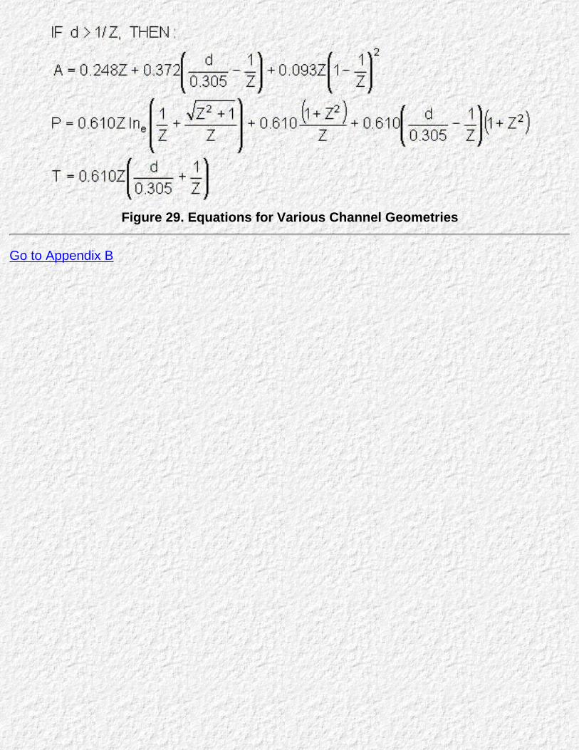
Figure 29. Equations for Various Channel Geometries
Go to Appendix B
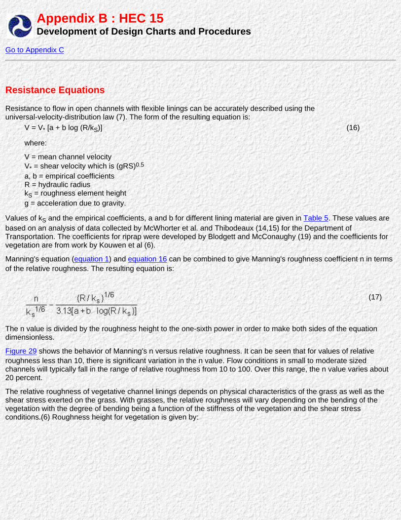
Appendix B : HEC 15Development of Design Charts and Procedures
Go to Appendix C
Resistance Equations
Resistance to flow in open channels with flexible linings can be accurately described using theuniversal-velocity-distribution law (7). The form of the resulting equation is:
V = V* [a + b log (R/kS)] (16)
where:
V = mean channel velocityV* = shear velocity which is (gRS)0.5
a, b = empirical coefficientsR = hydraulic radiuskS = roughness element heightg = acceleration due to gravity.
Values of kS and the empirical coefficients, a and b for different lining material are given in Table 5. These values arebased on an analysis of data collected by McWhorter et al. and Thibodeaux (14,15) for the Department ofTransportation. The coefficients for riprap were developed by Blodgett and McConaughy (19) and the coefficients forvegetation are from work by Kouwen et al (6).
Manning's equation (equation 1) and equation 16 can be combined to give Manning's roughness coefficient n in termsof the relative roughness. The resulting equation is:
(17)
The n value is divided by the roughness height to the one-sixth power in order to make both sides of the equationdimensionless.
Figure 29 shows the behavior of Manning's n versus relative roughness. It can be seen that for values of relativeroughness less than 10, there is significant variation in the n value. Flow conditions in small to moderate sizedchannels will typically fall in the range of relative roughness from 10 to 100. Over this range, the n value varies about20 percent.
The relative roughness of vegetative channel linings depends on physical characteristics of the grass as well as theshear stress exerted on the grass. With grasses, the relative roughness will vary depending on the bending of thevegetation with the degree of bending being a function of the stiffness of the vegetation and the shear stressconditions.(6) Roughness height for vegetation is given by:

equation 18
where:
h = average height of vegetation = Avg. shear stress
MEI = stiffness factor.
(18)
Values of h and MEI for various classifications of vegetative roughness, known as retardance classifications, are givenin Table 6.
The relative roughness for grasses in classifications A through E is typically less than 10. In this range, the variation inthe Manning's roughness coefficient is substantial, and it is not acceptable to use only an average value. By combiningequations 17 and 18, the Manning's roughness coefficient can be described as a function of hydraulic radius andtractive force. The resulting equation is:
equation 19
where:
C is 19.97 log (44.8 h0.6 MEI0.4) and depends on the class of vegetation.
(19)
Design charts for determining Manning's n for vegetative channel linings were developed by plotting values given byequation 19.
Table 5. Empirical Coefficients for Resistance EquationLining Material Ks a b
(ft) (mm)Woven Paper
Jute Mesh
Fiberglass Roving
Straw with Net
Curled Wood Mat
Synthetic Mat
Riprap
Vegetation
0.004
0.038
0.035
0.12
0.11
0.065
D50
equation 19
1.2
11.6
10.7
36.6
33.5
19.8
0.73
0.74
0.73
0.72
0.65
0.96
2.25
0.42
8.00
8.04
8.00
7.83
7.10
8.13
5.23
5.23
Table 6. Relative Roughness Parameters for VegetationRetardance Class Average Height, h Stiffness MEI
ft mm lb ft2 Newton m2
ABCDE
3.02.00.660.330.13
91061020010040
725 50 1.2 0.12 0.012
300 20 0.5 0.05 0.005

Figure 30. Manning's n versus Relative Roughness for Selected Lining Types.
Go to Appendix C

Appendix C : HEC 15Development of Steep Gradient Design Charts and Procedures
Go to Appendix D
General
The design of riprap for steep gradient channels presents special problems. On steep gradients, the riprap size required tostabilize the channel is often of the same order of magnitude as the depth of flow. The riprap elements often protrude from theflow, creating a very complex flow condition.
Laboratory studies and field measurements (20) of steep gradient channels have shown that additional factors need to beconsidered when computing hydraulic conditions and riprap stability. The development of design procedures for this manualhas, therefore, been based on equations that are more general in nature and account directly for several additional forcesaffecting riprap stability. The Bathurst resistance equation is used to predict hydraulic conditions in steep gradient channels andthe factor of safety method is used to assess riprap stability. A brief discussion of both methods is given in this Appendix A andthe assumptions used in developing the design procedures are presented.
Bathurst Resistance
Most of the flow resistance in channels with large-scale roughness is derived from the form drag of the roughness elements andthe distortion of the flow as it passes around roughness elements. Consequently, a flow resistance equation for these conditionshas to account for skin friction and form drag. Because of the shallow depths of flow and the large size of the roughnesselements, the flow resistance will vary with relative roughness area, roughness geometry, Froude number (the ratio of inertialforces to gravitational forces), and Reynolds number (the ratio of inertial forces to viscous forces).
Bathurst's experimental work quantified these relationships in a semi-empirical fashion. The work shows that for Reynoldsnumbers in the range of 4 x 10⁴ to 2 x 10⁵, resistance is likely to fall significantly as Reynolds number increases. For Reynoldsnumbers in excess of 2 x 10⁵, the Reynolds effect on resistance remains constant. When roughness elements protrude throughthe free surface, resistance increases significantly due to Froude number effects, i.e., standing waves, hydraulic jumps, andfree-surface drag. For the channel as a whole, free-surface drag decreases as the Froude number and relative submergenceincrease. Once the elements are submerged, Froude number effects related to free-surface drag are small, but those related tostanding waves are important.
The general dimensionless form of the Bathurst equation is:
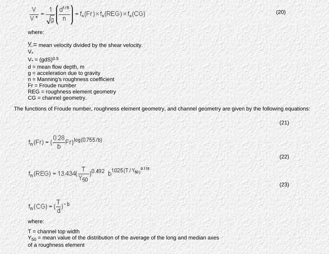
where:
V = mean velocity divided by the shear velocity.V*V* = (gdS)0.5
d = mean flow depth, mg = acceleration due to gravityn = Manning's roughness coefficientFr = Froude numberREG = roughness element geometryCG = channel geometry.
(20)
The functions of Froude number, roughness element geometry, and channel geometry are given by the following equations:
where:
T = channel top widthY50 = mean value of the distribution of the average of the long and median axesof a roughness element
(21)
(22)
(23)
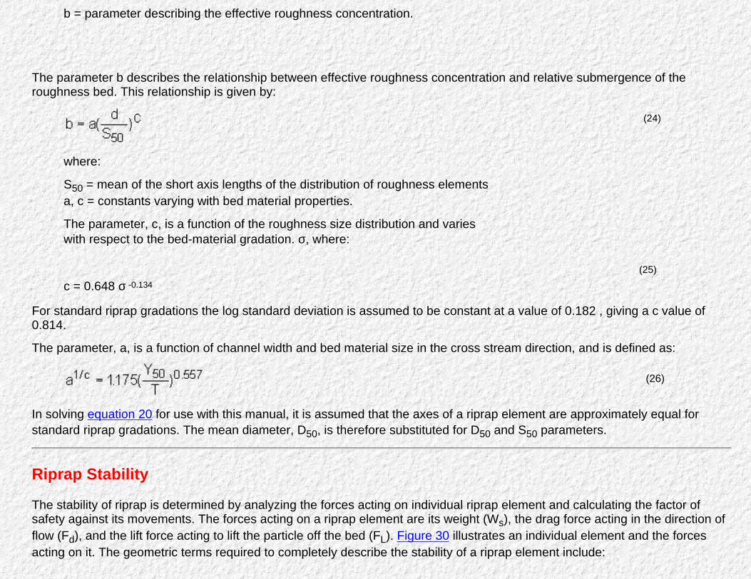
b = parameter describing the effective roughness concentration.
The parameter b describes the relationship between effective roughness concentration and relative submergence of theroughness bed. This relationship is given by:
where:
S50 = mean of the short axis lengths of the distribution of roughness elementsa, c = constants varying with bed material properties.
The parameter, c, is a function of the roughness size distribution and varieswith respect to the bed-material gradation. σ, where:
c = 0.648 σ -0.134
(24)
(25)
For standard riprap gradations the log standard deviation is assumed to be constant at a value of 0.182 , giving a c value of0.814.
The parameter, a, is a function of channel width and bed material size in the cross stream direction, and is defined as:
(26)
In solving equation 20 for use with this manual, it is assumed that the axes of a riprap element are approximately equal forstandard riprap gradations. The mean diameter, D50, is therefore substituted for D50 and S50 parameters.
Riprap Stability
The stability of riprap is determined by analyzing the forces acting on individual riprap element and calculating the factor ofsafety against its movements. The forces acting on a riprap element are its weight (Ws), the drag force acting in the direction offlow (Fd), and the lift force acting to lift the particle off the bed (FL). Figure 30 illustrates an individual element and the forcesacting on it. The geometric terms required to completely describe the stability of a riprap element include:

α = angle of the channel bed slopeβ, δ = angles between the two vectors: weight and drag, and their resultant in the plane of the side slope,respectivelyθ = angle of the channel side slopeφ= angle of repose for the riprap.
As the element will tend to roll rather than slide, its stability is analyzed by calculating the moments causing the particle to rollabout the contact point, c, with an adjacent riprap element as shown in Figure 30 . The equation describing the equilibrium ofthe particle is:
2 Ws cosθ = 1 Ws sinθ cosβ 3 Fd cosδ + 4 FL (27)
The factor of safety against movement is the ratio of moments resisting motion over the moments causing motion. This yields:
(28)
Where:
SF = Safety Factor
Evaluation of the forces and moment arms for equation 28 involves several assumptions and a complete derivation is given inSimons and Senturk.(21) The resulting set of equations are used to compute the factor of safety:
(29)
(30)
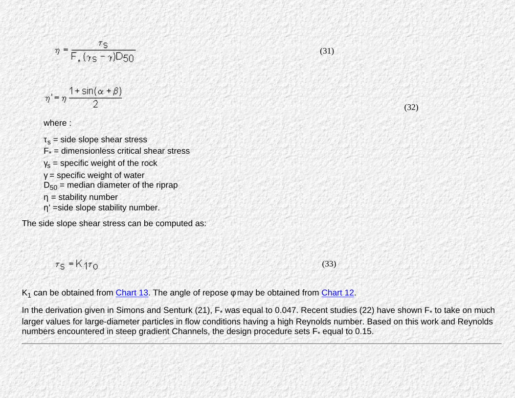
(31)
(32)
where :
τs = side slope shear stressF* = dimensionless critical shear stressγs = specific weight of the rockγ = specific weight of waterD50 = median diameter of the riprapη = stability numberη' =side slope stability number.
The side slope shear stress can be computed as:
(33)
K1 can be obtained from Chart 13. The angle of repose φ may be obtained from Chart 12.
In the derivation given in Simons and Senturk (21), F* was equal to 0.047. Recent studies (22) have shown F* to take on muchlarger values for large-diameter particles in flow conditions having a high Reynolds number. Based on this work and Reynoldsnumbers encountered in steep gradient Channels, the design procedure sets F* equal to 0.15.
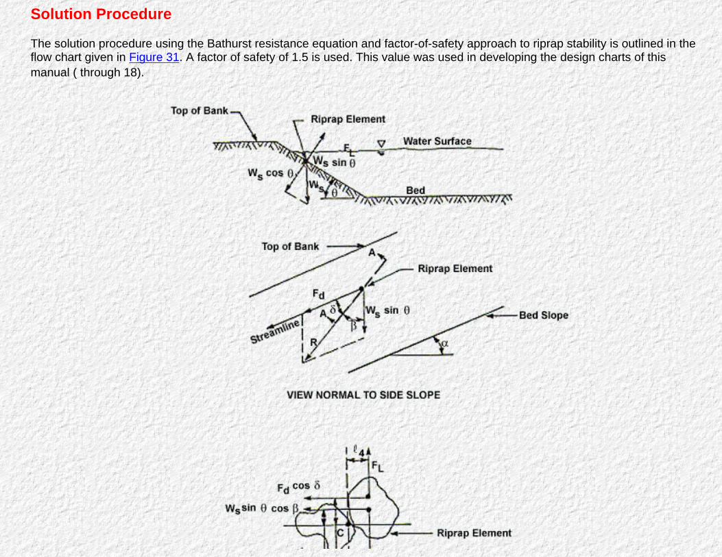
Solution Procedure
The solution procedure using the Bathurst resistance equation and factor-of-safety approach to riprap stability is outlined in theflow chart given in Figure 31. A factor of safety of 1.5 is used. This value was used in developing the design charts of thismanual ( through 18).
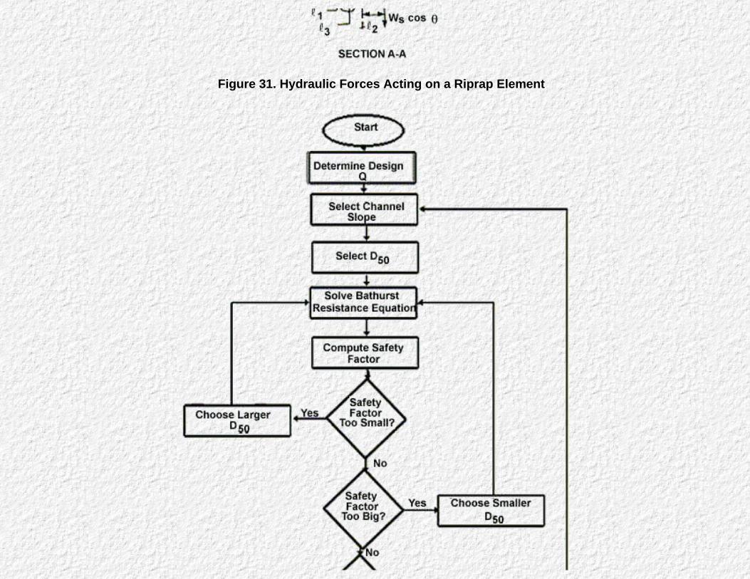
Figure 31. Hydraulic Forces Acting on a Riprap Element
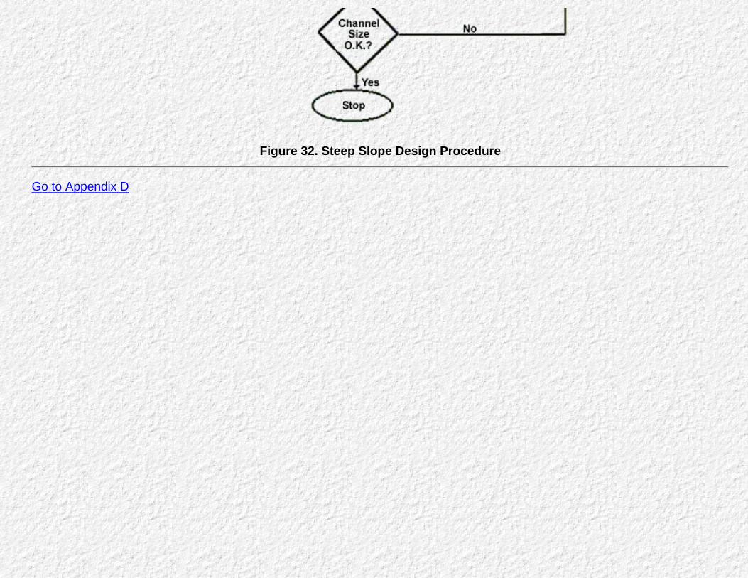
Figure 32. Steep Slope Design Procedure
Go to Appendix D

Appendix D : HEC 15Suggested Guideline Specifications
Go to Table of Contents
The Specifications in this Appendix A are presented for the information of the designer, and should be modified asrequired for each individual design.
Riprap
Description
This work consists of furnishing Materials and performing all work necessary to place riprap on bottoms andside slopes of channels, or as directed by the engineer.
The types of riprap included in this specification are:Rock riprap. Riprap consists of stone dumped in place on a filter blanket or prepared slope to form awell graded mass with a minimum of voids.
.
Gravel channel lining. Gravel placed on filter blanket or prepared slope to form a well graded masswith a minimum of voids.
b.
Materials
Rock riprap. Stone used for riprap shall be hard, durable, angular in shape; resistant to weathering andto water action; free from overburden, spoil, shale and organic material; and shall meet the gradationrequirements specified. Neither breadth nor thickness of a single stone should be less than one-third itslength. Rounded stone or boulders will not be accepted unless authorized by special provisions. Shaleand stone with shale seams are not acceptable. The minimum weight of the stone shall be 155 pounds
.

per cubic foot as computed by multiplying the specific gravity (bulk-saturated-surface-dry basis,AASHTO Test 85) times 62.3 pounds per cubic foot.
The sources from which the stone will be obtained shall be selected well in advance of the timewhen the stone will be required in the work. The acceptability of the stone will be determined byservice records and/or by suitable tests. If testing is required, suitable samples of stone shall betaken in the presence of the engineer at least 25 days in advance of the time when the placing ofriprap is expected to begin. The approval of some rock fragments from a particular quarry siteshall not be construed as constituting the approval of all rock fragments taken from that quarry.
In the absence of service records, resistance to disintegration from the type of exposure to whichthe stone will be subjected will be determined by any or all of the following tests as stated in thespecial provisions:
When the riprap must withstand abrasive action from material transported by thestream, the abrasion test in the Los Angeles machine shall also be used. Whenthe abrasion test in the Los Angeles machine ( AASHTO Test 96) is used, thestone shall have a percentage loss of not more than 40 after 500 revolutions.
1.
In locations subject to freezing or where the stone is exposed to salt water, thesulfate soundness test (AASHTO Test 104 for ledge rock using sodium sulfate)shall be used. Stones shall have a loss not exceeding 10 percent with thesulfate test after 5 cycles.
2.
When the freezing and thawing test (AASHTO Test 103 for ledge rockprocedure A) is used as a guide to resistance to weathering, the stone shouldhave a loss not exceeding 10 percent after 12 cycles of freezing and thawing.
3.
Each load of riprap shall be reasonably well graded from the smallest to the maximum sizespecified. Stones smaller than the specified 10 percent size and spells will not be permitted in anamount exceeding 10 percent by weight of each load.
Control of gradation will be by visual inspection. The contractor shall provide two samples of rockof at least 5 tons each, meeting the gradation specified. The sample at the construction site maybe a part of the finished riprap covering. The other sample shall be provided at the quarry. Thesesamples shall be used as a frequent reference for judging the gradation of the riprap supplied.Any difference of opinion between the engineer and the contractor shall be resolved by dumpingand checking the gradation of two random truck loads of stone. Mechanical equipment, a sortingsite, and labor needed to assist in checking gradation shall be provided by the contractor at noadditional cost to the State.Gravel channel lining. Gravel riprap shall consist of gravel or crushed rock of the thickness andb.

gradations shown on project drawings. All material comprising the riprap shall be composed of toughdurable particles reasonably free of thin, flat, or elongated particles and shall not contain organic matter.
Construction Requirements
General. Slopes to be protected by riprap shall be free of brush, trees, stumps, and other objectionableMaterials and be dressed to smooth surface. All soft or spongy material shall be removed to the depthshown on the plans or as directed by the engineer and replaced with approved native material. Filledareas will be compacted and a toe trench as shown on the plans shall be dug and maintained until theriprap is placed.
.
Protection for structured foundations shall be provided as early as the foundation constructionpermits. The area to be protected shall be cleared of waste Materials and the surfaces to beprotected prepared as shown on the plans. The type of riprap specified will be placed inaccordance with these specifications as modified by the special provisions.
When shown on the plans, a filter blanket or filter fabric shall be placed on the prepared slope orarea to be provided with foundation protection as specified before the stone is placed.
The contractor shall maintain the riprap until all work on the contract has been completed andaccepted. Maintenance shall consist of the repair of areas where damaged by any cause.Rock riprap. Stone for riprap shall be placed on the prepared slope or area in a manner which willproduce a reasonably well-graded mass of stone with the minimum practicable percentage of voids.The entire mass of stone shall be placed so as to be in conformance with the lines, grades, andthicknesses shown on the plans. Riprap shall be placed to its full course thickness at one operation andin such a manner as to avoid displacing the underlying material. Placing of riprap in layers, or bydumping into chutes, or by similar methods likely to cause segregation, will not be permitted.
b.
The larger stones shall be well distributed and the entire mass of stone shall conform to thegradation specified by the engineer. All material going into riprap protection shall be so placedand distributed so that there will be no large accumulations of either the larger or smaller sizes ofstone.
It is the intent of these specifications to produce a fairly compact riprap protection in which allsizes of material are placed in their proper proportions. Hand placing or rearranging of individualstones by mechanical equipment may be required to the extent necessary to secure the resultsspecified.
Unless otherwise authorized by the engineer, the riprap protection shall be placed in conjunctionwith the construction of the embankment with only sufficient lag In construction of the riprapprotection as may be necessary to allow for proper construction of the portion of the embankmentprotected and to prevent mixture of embankment and riprap. The contractor shall maintain theriprap protection until accepted, and any material displaced by any cause shall be replaced to thelines and grades shown on the plans at no additional cost to the State.
When riprap and filter material are dumped under water, thickness of the layers shall be increasedas shown on the plans; and methods shall be used that will minimize segregation.Gravel channel Lining. Gravel for riprap shall be placed on the prepared slope or area.c.
Measurement for Payment
The quantity of riprap to be paid for, of specified thickness and extent, in place and accepted, shall bemeasured by the number of cubic yards as computed from surface measurements parallel to the riprapsurface and thickness measured normal to the riprap surface. riprap placed outside the specified limits willnot be measured or paid for, and the contractor may be required to remove and dispose of the excess riprapwithout cost to the State.
Basis for Payment
Quantities shall be paid for at the contract unit price per cubic yard and shown in the bid schedule which priceshall be full compensation for furnishing all material, tools, and labor; the preparation of the subgrade; theplacing of the riprap; the grouting when required; and all other work incidental to finished construction inaccordance with these specifications.
Wire Enclosed Riprap

Description
This work will consist of furnishing all materials and performing all work necessary to place wire enclosedriprap on bottoms and side slopes of channels or as directed by the engineer. Wire enclosed riprap consistsof mats or baskets fabricated from wire mesh, filled with stone, connected together, and anchored to theslope. Details of construction may differ depending upon the degree of exposure and the service, whetherused for revetment or used as a toe protection for other types of riprap.
Materials
Material requirements shall meet those given for riprap, except for size and gradation of stone. Stone usedshall be well graded and the smallest dimension of 70 percent of stone, by weight, shall exceed the wiremesh opening. The maximum size of stone, measured normal to the slope, shall not exceed the mat orbasket thickness.
Wire mesh shall be galvanized woven fencing conforming to the specifications for fence fabric, and shall be ofthe gage and dimensions shown on the plans. Ties and lacing wire shall be No. 9 gage galvanized unlessotherwise specified.
Construction Requirements
Construction requirements shall meet those given for rock riprap. Wire enclosed segments shall be hand-ormachine-formed to the dimensions shown on the plans. These units shall be placed, laced, and filled toprovide a uniform, dense, protective coat over the area specified.
Perimeter edges of wire enclosed units are to be securely selvedged or bound so that the joints formed bytying the selvedges have approximately the same strength as the body of the mesh. Wire-enclosed units shallbe tied to its neighbors along all contacting edges at 1 foot intervals in order to form a continuous connectingstructure.
Mattresses and baskets on channel side slopes should be tied to the banks by anchor stakes driven 4 feetinto tight soil (clay) and 6 feet into loose soil (sand). The anchor stakes should be located at the insidecorners of mattress or basket diaphragms along an upslope (highest) wall, so that the stakes are an integralpart of the mattress or basket. The exact maximum spacing of the stakes depends upon the configuration ofthe mattress or basket; however, the following is the minimum spacing: Stakes every 6 feet along and downthe slope for slopes 2.5H:1V and steeper, and every 9 feet along and down the slope for slopes flatter than2.5H:1V.
Channel linings should be tied to the channel banks with wire-enclosed riprap counterforts at least every 12inches. Counterfronts should be keyed at least 12 inches into the existing banks with slope mattress orbasket linings and should be keyed at least 3 feet by turning the counterfront endwise when the lining isdesigned to serve as a retaining wall.
Measurement for Payment
The quantity of wire-enclosed riprap of specified thickness and extent in place and accepted, shall bemeasured by the number of square yards obtained by measurements parallel to the riprap surface. Riprapplaced outside the specified limits will not be measured or paid for, and the contractor may be required toremove and dispose of the excess riprap without cost to the State.
Basis for Payment
Quantities shall be paid for at the contract unit price per square yards and shown in the bid schedule, whichprice shall be full compensation for furnishing all material, tools, and labor; the preparation of the subgrade;the placing of the stone; and all other work incidental to finished construction in accordance with thesespecifications.
Woven Paper Net
Description
This work shall consist of furnishing materials and all work necessary to install woven paper net fabric forerosion control on roadway, ditches, or slopes, or as directed by the engineer.
Materials
Materials shall consist of knitted plastic net, interwoven with paper strips. The yarn shall be ofphotodegradable synthetic types and the paper shall be biodegradable. Staples shall be 6 inches and 12inches in length, and composed of high carbon iron.
Construction Requirements
Woven paper net shall be placed on the prepared slope or seedbed area which has been prepared andleveled according to various other sections in these specifications. If seeding and fertilizer are in theprovisions, they should be applied immediately before laying the fabric.
Woven paper net shall be applied on slopes with the fabric running vertical from the top of the slope. Indrainage's, woven paper net shall be applied in the direction of the water flow. The fabric shall be securedand buried in a 4 inch trench, 1 foot back from the crown and at the bottom of the slope. Heavy gauge staplesshall secure the fabric at 9 inch intervals along the edges and overlaps and at 3 foot intervals down the centerof the fabric roll. Rolls shall overlap 4 inches. Woven paper net shall be draped rather than stretched acrossthe surface.
The contractor shall maintain the fabric blanket until all work on the contract has been completed andaccepted. Maintenance shall consist of the repair of areas where damaged by any cause. All damaged areasshall be repaired to reestablish the condition and grade of the soil prior to application of the covering and shallbe refertilized, reseeded, and remulched as directed.
Measurement for Payment
The quantity of woven paper net, including staples, completely in place and accepted, shall be measured bythe square yard of finished surface. No allowance will be made for overlap. Woven paper net placed outsidethe specified limits will not be measured or paid for and the contractor may be required to remove or disposeof the excess without cost to the state.
Basis for Payment
Quantities shall be paid for at the contract unit price per square yard which price shall be full compensationfor furnishing all Materials, tools, and labor; the preparation of the subgrade; the placing of the woven papernet; and all other work incidental to finished construction in accordance with these specifications.

Jute Net
Description
This work consists of furnishing materials and performing all work necessary to install jute net on roadwayditches or slopes or as directed by the engineer.
Materials
Jute net shall consist of heavy mesh of a uniform open plain weave of unbleached, smolder-resistant, singlejute yarn. The yarn shall be of a loosely twisted construction having an average twist of not less than 1.6 turnsper inch and shall not vary in thickness by more than one-half its normal diameter. The jute net shall befurnished in approximately 90-pounds rolled strips and shall meet the following requirements:
Length: approximately 75 yardsWidth: 48 inches + 1 inch 78 warp ends per width of cloth 41 weft ends per yardWeight: 1.22 lb per linear yard with + 5 percent
Staples shall be 3, 6, and 12 inches in length, and composed of high carbon iron or as specified by theengineer.
Construction Requirements
The blankets shall be placed in designated locations immediately after seeding and mulching operations havebeen completed. The material shall be applied smoothly but loosely to the soil surface without stretching. Theupslope end of each piece of jute net shall be buried in a narrow trench 6 inches deep. After the jute is buried,the trench shall be firmly tamped closed.
In cases where one roll of jute mesh ends and a second roll starts, the upslope piece should be brought over
the buried end of the second roll so that there is a 12 inch overlap to form a junction slot. Where two or morewidths of jute net are applied side by side, an overlap of at least 4 inches must be made.
Check slots should be made before the jute net is rolled out. A narrow trench should be dug across the slopeperpendicular to the direction of flow. A piece of jute, cut the same length as the trench, is folded lengthwise.The fold is placed in the trench and the trench is tamped closed. The portion of the jute remaining aboveground is unfolded and laid flat on the soil surface. Check slots will be spaced so that one check slot orjunction slot occurs without each 50 feet of slope. Overlaps which run down the slope, outside edges andcenters shall be stapled on 2-foot intervals. Each width of jute net will have a row of staples down the centeras well as along each edge. Check slots and junction slots will be stapled across at 6 inch intervals.
For extra hard soil, use 0.075 sharp-pointed fence-type staples, composed of hardened steel.
The jute net must be spread evenly and smoothly and be in contact with the seeded area at all points. Thecontractor shall maintain the jute mesh until all work on the contract has been completed and accepted.Maintenance shall consist of the repair of areas where damaged by any cause. All damaged areas shall berepaired to reestablish the condition and grade of the soil prior to application of the covering and shall berefertilized, reseeded and remulched as directed.
Measurement for Payment
The quantity of jute net, including staples, completely in place and accepted, shall be measured by thesquare yard of finished surface. No allowance will be made for overlap. Mat placed outside the specified limitswill not be measured or paid for, and the contractor may be required to remove and dispose of the excessmat without cost to the State.
Basis for Payment
Quantities shall be paid for at the contract unit price per square yard which price shall be full compensationfor furnishing all Materials, tools, and labor; the preparation of the subgrade; the placing of the jute net; andall other work incidental to finished construction in accordance with these specifications.
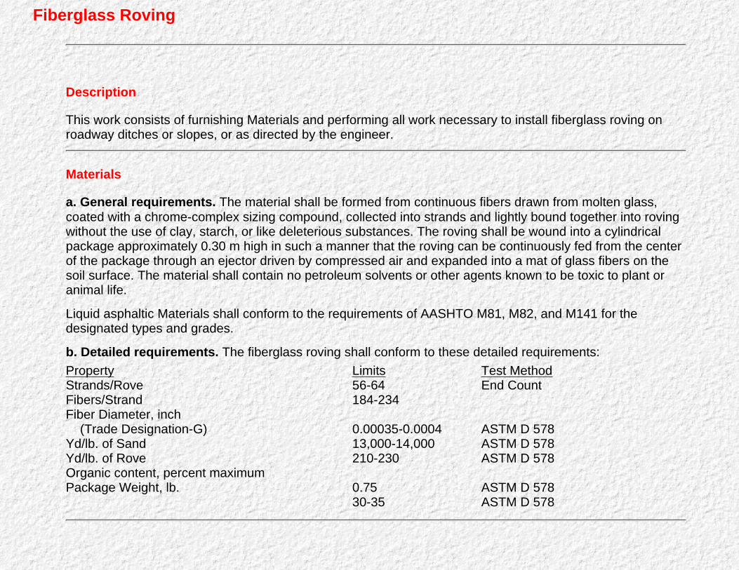
Fiberglass Roving
Description
This work consists of furnishing Materials and performing all work necessary to install fiberglass roving onroadway ditches or slopes, or as directed by the engineer.
Materials
a. General requirements. The material shall be formed from continuous fibers drawn from molten glass,coated with a chrome-complex sizing compound, collected into strands and lightly bound together into rovingwithout the use of clay, starch, or like deleterious substances. The roving shall be wound into a cylindricalpackage approximately 0.30 m high in such a manner that the roving can be continuously fed from the centerof the package through an ejector driven by compressed air and expanded into a mat of glass fibers on thesoil surface. The material shall contain no petroleum solvents or other agents known to be toxic to plant oranimal life.
Liquid asphaltic Materials shall conform to the requirements of AASHTO M81, M82, and M141 for thedesignated types and grades.
b. Detailed requirements. The fiberglass roving shall conform to these detailed requirements:Property Limits Test MethodStrands/RoveFibers/StrandFiber Diameter, inch (Trade Designation-G)Yd/lb. of SandYd/lb. of RoveOrganic content, percent maximumPackage Weight, lb.
56-64184-234
0.00035-0.000413,000-14,000210-230
0.7530-35
End Count
ASTM D 578ASTM D 578ASTM D 578
ASTM D 578ASTM D 578

Construction Requirements
The fiberglass roving shall be applied over the designated area within 24 hours after the normal seedingoperations have been completed.
The fiberglass roving shall be spread uniformly over the designated area to form a random mat of continuousglass fibers at the rate of 0.25 pounds per square yard. This rate may be varied as directed by the engineer.
The fiberglass roving shall be anchored to the ground with the asphaltic Materials applied uniformly over theglass fibers at the rate of 0.25 gallon per square yard. This rate may be varied as directed by the engineer.
The upgrade end of the lining shall be buried to a depth of 1 foot to prevent undermining. Instructions forslope and ditch protection may be stipulated by the engineer to fit the field conditions encountered.
The contractor shall maintain the roving until all work on the contract has been completed and accepted.Maintenance shall consist of the repair of areas where damaged by any cause. All damaged areas shall berepaired to reestablish the condition and grade of the soil prior to application of the covering and shall berefertilized, reseeded and remulched as directed.
Measurement for Payment
Fiberglass roving will be measured by the pound, and the quantity to be measured will be that actually usedon the project. Roving placed outside the specified limits will not be paid for and the contractor may berequired to remove and dispose of the excess roving without cost to the State.
Basis for Payment
Quantities shall be paid for at the contract unit price per pound and shown in the bid schedule, which priceshall be full compensation for furnishing all Materials, tools, and labor; the preparation of the subgrade, theplacing of the roving, and all other work incidental to finished construction in accordance with thesespecifications.
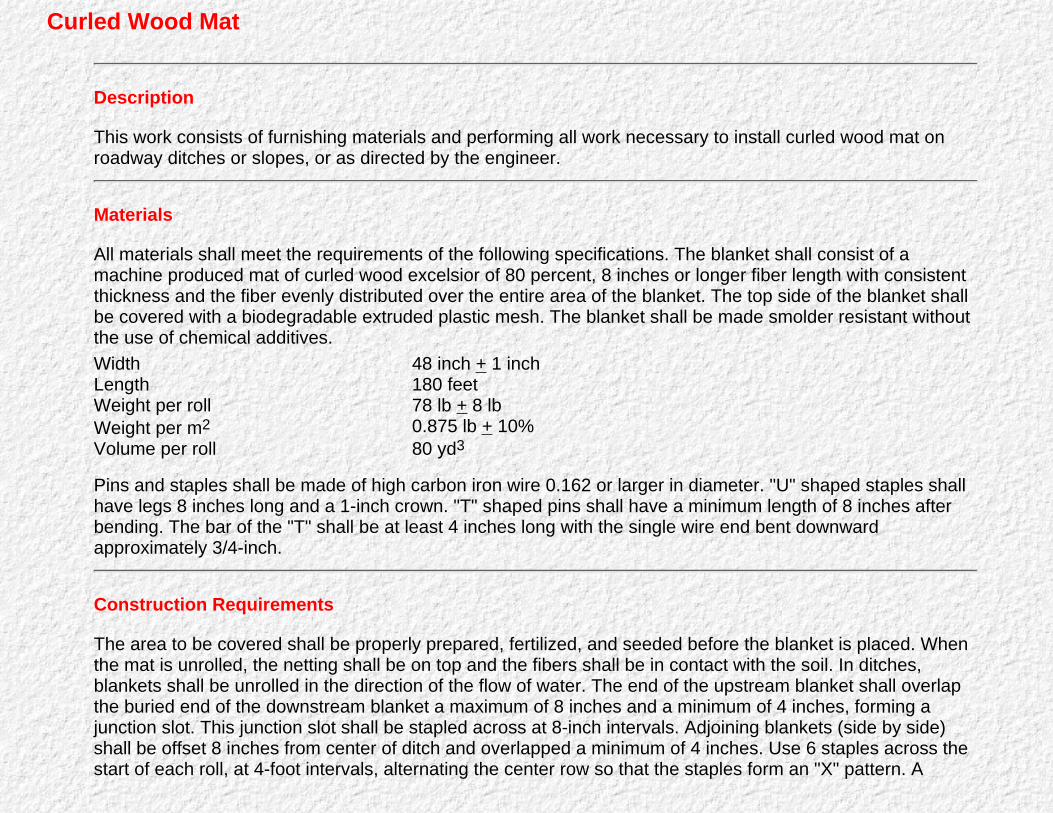
Curled Wood Mat
Description
This work consists of furnishing materials and performing all work necessary to install curled wood mat onroadway ditches or slopes, or as directed by the engineer.
Materials
All materials shall meet the requirements of the following specifications. The blanket shall consist of amachine produced mat of curled wood excelsior of 80 percent, 8 inches or longer fiber length with consistentthickness and the fiber evenly distributed over the entire area of the blanket. The top side of the blanket shallbe covered with a biodegradable extruded plastic mesh. The blanket shall be made smolder resistant withoutthe use of chemical additives.WidthLengthWeight per rollWeight per m2
Volume per roll
48 inch + 1 inch180 feet78 lb + 8 lb0.875 lb + 10%80 yd3
Pins and staples shall be made of high carbon iron wire 0.162 or larger in diameter. "U" shaped staples shallhave legs 8 inches long and a 1-inch crown. "T" shaped pins shall have a minimum length of 8 inches afterbending. The bar of the "T" shall be at least 4 inches long with the single wire end bent downwardapproximately 3/4-inch.
Construction Requirements
The area to be covered shall be properly prepared, fertilized, and seeded before the blanket is placed. Whenthe mat is unrolled, the netting shall be on top and the fibers shall be in contact with the soil. In ditches,blankets shall be unrolled in the direction of the flow of water. The end of the upstream blanket shall overlapthe buried end of the downstream blanket a maximum of 8 inches and a minimum of 4 inches, forming ajunction slot. This junction slot shall be stapled across at 8-inch intervals. Adjoining blankets (side by side)shall be offset 8 inches from center of ditch and overlapped a minimum of 4 inches. Use 6 staples across thestart of each roll, at 4-foot intervals, alternating the center row so that the staples form an "X" pattern. A

common row of staples shall be used on adjoining blankets.
The contractor shall maintain the blanket until all work on the contract has been completed and accepted.Maintenance shall consist of the repair of areas where damaged by any cause. All damaged areas shall berepaired to reestablish the condition and grade of the soil prior to application of the covering and shall berefertilized, reseeded, and remulched as directed.
Measurement for Payment
Curled wood mat, including staples, completely in place and accepted, will be measured by the square yardof finished surface. No allowance will be made for overlap. Mat placed outside the specified limits will not bemeasured or paid for, and the contractor may be required to remove and dispose of the excess without costto the State.
Basis for Payment
Quantities shall be paid for at the contract unit price per square yard and shown in the bid schedule, whichprice shall be full compensation for furnishing all materials, tools, and labor; the preparation of the subgrade;the placing of the matting; and all other work incidental to finished construction in accordance with thesespecifications.
Straw with Net
Description
This work consists of furnishing materials and performing all work necessary to install straw with net onroadway ditches or slopes, or as directed by the engineer.

Materials
Straw. Straw shall be derived from wheat, oats, or barley. The contractor shall furnish evidence thatclearance has been obtained from the county agricultural commissioner, as required by law, beforestraw obtained from outside the county in which it is to be used is delivered to the site of the work.Straw that has been used for stable bedding shall not be used.
.
Plastic net shall be an extruded polypropylene or other approved plastic material, extruded in such amanner as to form a net of 3/4-inch minimum square openings. The net shall be furnished in rolls tomeet the following characteristics:
b.
WidthLengthWeight
48 inch, minimum50 yard, minimum, convenient lengths2.6 lb/1000 f2, minimum
Pins and staples shall be made of high carbon iron wire 0.162 or larger in diameter. "U" shaped staplesshall have legs 8 inches long and a 1-inch crown. "T" shaped pins shall have a minimum length of 8inches after bending. The bar of the "T" shall be at least 4 inches long with the single wire end bentdownward approximately 3/4 inch.
c.
Construction Requirements
Plastic net shall be placed as soon as possible after mulching operations have been completed in locationsdesignated in the plans. Net shall be used only to secure straw mulch to the finished slope or ditch.
Preparation shall include all the work required to make ready the areas for incorporating straw. Areas onwhich straw is to be applied shall be prepared such that the straw will be incorporated into the soil to thedegree specified. Removing and disposing of rocks and debris from embankments constructed as part of thework will be considered as included in the contract price paid per ton for straw and no additionalcompensation will be allowed therefore.
Straw shall be uniformly spread at the rate specified in the special provisions. When weather conditions aresuitable, straw may be pneumatically applied by means of equipment which will not render the strawunsuitable for incorporation into the soil.
Straw shall be incorporated into the soil with a roller equipped with straight studs, made of approximately7/8-inch steel plate, placed approximately 8 inches apart, and staggered. The studs shall not be less than 6inches long or more than 6 inches wide, and shall be rounded to prevent withdrawing the straw from the soil.The roller shall be of such weight as to incorporate the straw sufficiently into the soil so that the straw will on

and will leave a uniform surface.
The net shall be applied smoothly but loosely on the mulched surface without stretching. The net shall beunrolled from the top to the bottom of the slope. The top edge of the net shall be buried and stapled at of theslope in a narrow trench 6 inches deep. After the edge is buried and stapled, the trench shall be backfilledand tamped.
In cases where one roll of net ends and a second roll starts, the upslope piece shall be brought over the startof the second roll so that there is a 4-inch overlap.
Where two or more widths of net are applied side by side, an overlap of at least 6 inches must be made.Insert 1 staple every foot along top and bottom of edges of the net. Also, insert staples over 4 feet on eachedge and down center of net so that the staples alternate between edges and center to form an X shapepattern
The contractor shall maintain the straw with net until all work on the contract has been completed andaccepted. Maintenance shall consist of the repair of areas where damaged by any cause. All damaged areasshall be repaired to reestablish the condition and grade of the soil prior to application of the covering and shallbe refertilized, reseeded, and remulched as directed.
Measurement for Payment
Straw with net, including staples, completely in place and accepted, will be measured by the square yard offinished surface. No allowance will be made for overlap. Straw and net placed outside the specified limits willnot be measured or paid for, and the contractor may be required to remove and dispose of the excess netwithout cost to the State.
Basis for Payment
Quantities shall be paid for at the contract unit price per square yard and shown in the bid schedule whichprice shall be full compensation for furnishing all materials, tools, and labor; the preparation of the subgrade;and all other work incidental to finished construction in accordance with these specifications.

Synthetic Mat
Description
This work consists of furnishing materials and performing all work necessary to install nylon mat on roadwayditches or slopes, or as directed by the engineer.
Materials
Synthetic mat shall consist of three-dimensional structure of entangled nylon monofilaments, melt-bonded attheir intersections, forming a stable mat of suitable weight and configuration. The mat shall be crush-resistant,pliable, resilient, water-permeable, and highly resistant to chemicals and environmental degradation. The matshall comply with the following physical properties:Material type Nylon 6 plus a minimum content of
0.5 percent by weight of carbon blackFilament diameter 0.157 inch, minimumWeight 0.747 + 0.075 lb/yd2
Thickness 0.70 in, minimumNominal width of roll 38 inNominal length of roll 109 ydColor BlackTensile properties1
Strength Length direction 7.5 lb/in, minimum Width direction 4.4 lb/in, minimum Elongation Length direction 50 percent, minimum Width direction 50 percent, minimumResiliency2
30 minute recovery 80 percent, minimum (3 cycles)
1ASTM D 1682 Strip test procedure modified to obtain filament bond strength to indicate tensile properties.
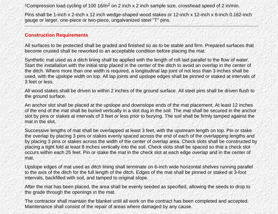
2Compression load cycling of 100 16/in2 on 2 inch x 2 inch sample size, crosshead speed of 2 in/min.
Pins shall be 1-inch x 2-inch x 12 inch wedge-shaped wood stakes or 12-inch x 12-inch x 6-inch 0.162-inchgauge or larger, one-piece or two-piece, ungalvanized steel "T" pins.
Construction Requirements
All surfaces to be protected shall be graded and finished so as to be stable and firm. Prepared surfaces thatbecome crusted shall be reworked to an acceptable condition before placing the mat.
Synthetic mat used as a ditch lining shall be applied with the length of roll laid parallel to the flow of water.Start the installation with the initial strip placed in the center of the ditch to avoid an overlap in the center ofthe ditch. Where more than one width is required, a longitudinal lap joint of not less than 3 inches shall beused, with the upslope width on top. All lap joints and upslope edges shall be pinned or staked at intervals of3 feet or less.
All wood stakes shall be driven to within 2 inches of the ground surface. All steel pins shall be driven flush tothe ground surface.
An anchor slot shall be placed at the upslope and downslope ends of the mat placement. At least 12 inchesof the end of the mat shall be buried vertically in a slot dug in the soil. The mat shall be secured in the anchorslot by pins or stakes at intervals of 3 feet or less prior to burying. The soil shall be firmly tamped against themat in the slot.
Successive lengths of mat shall be overlapped at least 3 feet, with the upstream length on top. Pin or stakethe overlap by placing 3 pins or stakes evenly spaced across the end of each of the overlapping lengths andby placing 3 pins or stakes across the width of the center of overlap area. Check slots shall be constructed byplacing a tight fold at least 8 inches vertically into the soil. Check slots shall be spaced so that a check slotoccurs within each 25 feet. Pin or stake the mat in the check slot at each edge overlap and in the center ofmat.
Upslope edges of mat used as ditch lining shall terminate on 6-inch wide horizontal shelves running parallelto the axis of the ditch for the full length of the ditch. Edges of the mat shall be pinned or staked at 3-footintervals, backfilled with soil, and tamped to original slope.
After the mat has been placed, the area shall be evenly seeded as specified, allowing the seeds to drop tothe grade through the openings in the mat.
The contractor shall maintain the blanket until all work on the contract has been completed and accepted.Maintenance shall consist of the repair of areas where damaged by any cause.

Measurement for Payment
Synthetic mat, including pins or stakes, complete, in place, and accepted, will be measured by the squareyard of finished surface. Mat placed outside the specified limits will not be measured or paid for and thecontractor may be required to remove and dispose of the excess mat without cost to the State.
Basis for Payment
Quantities shall be paid for at the contract unit price per square yard and shown in the bid schedule, whichprice shall be full compensation for furnishing all materials, tools, and labor; the preparation of the subgrade;placing of the mats; and all other work incidental to finished construction in accordance with thesespecifications.
Filter Blanket
Description
This work consists of furnishing materials and performing all work necessary to install filter blanket onroadway ditches or slopes, or as directed by the engineer.
Materials
The filter blanket will consist of one or more layers of gravel, crushed rock, or sand, of the thickness shownon the plans. The gradation of material in each layer of the filter blanket shall meet the requirements of thespecial provisions. All material comprising the filter blanket shall be composed of tough, durable particles;reasonably free from thin, flat, and elongated pieces; and shall be free from organic matter.

Construction Requirements
A filter blanket shall be placed on the prepared slope or area to the full specified thickness of each layer inone operation, using methods which will not cause segregation of particle sizes within the filter material. Thesurface of the finished layer should be reasonably even and free from mounds or windows. Multiple layers offilter material, when shown on the plans, shall be placed in the same manner, using methods which will notcause mixture of the material in the different layers.
The filter blanket shall be placed in accordance with various sections of these specifications requiring the useof a filter blanket or as specified by the engineer.
The contractor shall maintain the blanket until all work on the contract has been completed and accepted.Maintenance shall consist of the repair of areas where damaged by any cause.
Measurement for Payment
The quantity of filter blanket to be paid for, of specified thickness and extent, in place and accepted, shall bemeasured by the number of cubic yards as computed from surface measurement parallel to the riprap surfaceand thickness measured normal to the riprap surface. Blanket placed outside the specified limits will not bemeasured or paid for, and the contractor may be required to remove and dispose of the excess without costto the State.
Basis for Payment
Quantities shall be paid for at the contract unit price per cubic yard, which price shall be full compensation forfurnishing all materials, tools, and labor; the preparation of the subgrade; placing of the filter blanket ; and allother work incidental to finished construction in accordance with these specifications.
Engineering Fabric

Description
This work consists of furnishing materials and performing all work necessary to install engineering fabric onroadway ditches or slopes, or as directed by the engineer.
Materials
The filter fabric shall be manufactured of polyester, nylon or polypropylene material, or a combination thereof.The material shall not act as a wicking agent, shall be permeable, and shall conform to the following criteria: For Edge Drains For UnderdrainsWeight, ounces/yd2, minimum ASTM Designation D 1910
Grab tensIle strength (1-inch grip), lb, minimum
Elongation, percent, minimum ASTM Designation, D 1682
Toughness, lb, minimum (percent elongation x grab tensilestrength)
40
50
10
3,000
4.0
90
10
4,000
Construction Requirements
Engineering fabric shall be placed to the specified thickness in accordance with various sections of thesespecifications requiring the use of an engineering fabric or as specified by the engineer. The contractor shallmaintain the fabric until all work on the contract has been completed and accepted. Maintenance shall consistof the repair of areas where damaged by any cause.
Measurement for Payment
Engineering fabric to be paid for, of specified thickness and extent, in place and accepted, will be measuredin square yards in accordance with the provisions in the various sections of these specifications, requiring theuse of engineering fabric.

Basis for Payment
Quantities shall be paid for in accordance with the provisions in the various sections of these specificationsrequiring the use of engineering fabric.
Go to Table of Contents
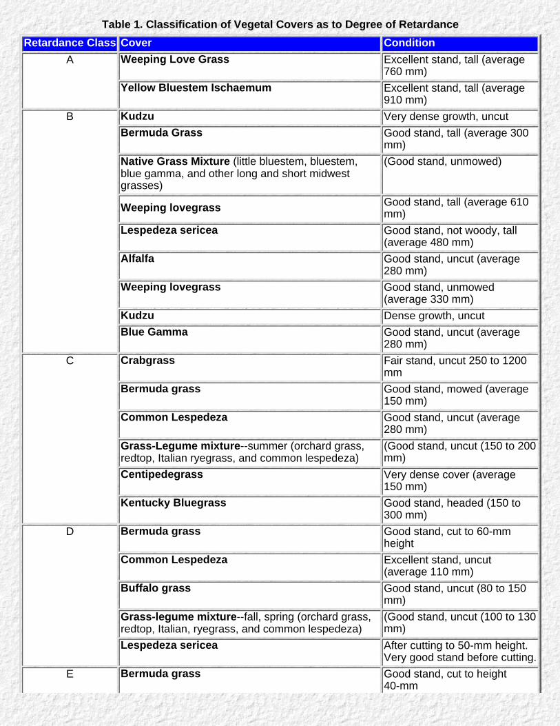
Table 1. Classification of Vegetal Covers as to Degree of RetardanceRetardance Class Cover Condition
A Weeping Love Grass Excellent stand, tall (average760 mm)
Yellow Bluestem Ischaemum Excellent stand, tall (average910 mm)
B Kudzu Very dense growth, uncutBermuda Grass Good stand, tall (average 300
mm)Native Grass Mixture (little bluestem, bluestem,blue gamma, and other long and short midwestgrasses)
(Good stand, unmowed)
Weeping lovegrass Good stand, tall (average 610mm)
Lespedeza sericea Good stand, not woody, tall(average 480 mm)
Alfalfa Good stand, uncut (average280 mm)
Weeping lovegrass Good stand, unmowed(average 330 mm)
Kudzu Dense growth, uncutBlue Gamma Good stand, uncut (average
280 mm)C Crabgrass Fair stand, uncut 250 to 1200
mmBermuda grass Good stand, mowed (average
150 mm)Common Lespedeza Good stand, uncut (average
280 mm)Grass-Legume mixture--summer (orchard grass,redtop, Italian ryegrass, and common lespedeza)
(Good stand, uncut (150 to 200mm)
Centipedegrass Very dense cover (average150 mm)
Kentucky Bluegrass Good stand, headed (150 to300 mm)
D Bermuda grass Good stand, cut to 60-mmheight
Common Lespedeza Excellent stand, uncut(average 110 mm)
Buffalo grass Good stand, uncut (80 to 150mm)
Grass-legume mixture--fall, spring (orchard grass,redtop, Italian, ryegrass, and common lespedeza)
(Good stand, uncut (100 to 130mm)
Lespedeza sericea After cutting to 50-mm height.Very good stand before cutting.
E Bermuda grass Good stand, cut to height40-mm

Bermuda grass Burned stubbleNote: Covers classified have been tested in experimental channels. Covers were green and generallyuniform.

Table 2. Permissible Shear Stresses for Lining MaterialLining Category Lining Type Permissible Unit Shear Stress1
lb/ft2 N/m2
Temporary* Woven Paper NetJut NetFiberglass Roving: Single DoubleStraw with netCurled Wood MatSynthetic Mat
0.150.45
0.600.851.451.552.00
7.221.5
28.740.769.474.295.8
Vegetative Class AClass BClass CClass DClass E
3.702.101.000.600.35
177.2100.647.928.716.8
Gravel Riprap2 25 mm50 mm
0.330.67
15.831.6
Rock Riprap2 150 mm300 mm
2.004.00
95.8191.5
Bare Soil non-cohesiveCohesive
See Chart 1See Chart 2
1Based on Data in 5,8,13,14,15.2Based on equation 8(Current practice is to use 5D50 Some "temporary" linings become permanent when buried.

Table 3. Manning's Roughness CoefficientsLining Category Lining Type n-Values
Depth Ranges
(0-150 mm) (150-600 mm) (> 600 mm)Rigid Concrete
Grouted RiprapStone MasonrySoil CementAsphalt
0.0150.0400.0420.0250.018
0.0130.0300.0320.0220.016
0.0130.0280.0300.0200.016
Unlined Bare SoilRock Cut
0.0230.045
0.0200.035
0.0200.025
Temporary* Woven Paper NetJute NetFiberglass RovingStraw With NetCurled Wood MatSynthetic Mat
0.0160.0280.0280.0650.0660.036
0.0150.0220.0210.0330.0350.025
0.0150.0190.0190.0250.0280.021
Gravel Riprap 25 mm D5050 mm D50
0.0440.066
0.0330.041
0.0300.034
Rock Riprap 150 mm D50300 mm D50
0.104--
0.0690.078
0.0350.040
* Some temporary Linings become permanent when buried.1Based on data in 5,8,13,14,and 15Note: Values listed are representative values for the respective depth ranges. Manning's roughnesscoefficients, n, vary with the flow depth. See Appendix B.

List of Tables for HEC 15-Design of Roadside Channels with Flexible Linings (Metric)
Back to Table of Contents
Table 1. Classification of Vegetal Covers as to Degree of Retardance
Table 2. Permissible Shear Stress for Lining Material
Table 3. Manning's Roughness Coefficients
Table 4. Values of A3/Az for Selection Side Slope and Depth to Bottom Width Ratios
Table 5. Empirical Coefficients for Resistance Equation
Table 6. Relative Roughness Parameters for Vegetation
Back to Table of Contents

List of Charts & Forms for HEC 15-Design of Roadside Channels with Flexible Linings(Metric)
Back to Table of Contents
Chart 1. Permissible Shear Stress for Non-Cohesive Soils (after 15)
Chart 2. Permissible Shear Stress for Cohesive Soils (after 16)
Chart 3. Solution of Manning's Equation for Channels of Various Side Slopes (after 17)
Chart 4. Geometric Design Chart for Trapezoidal Channels
Chart 5. Manning's n versus Hydraulic Radius, R, for Class A Vegetation (after 5)
Chart 6. Manning's n versus Hydraulic Radius, R, for Class B Vegetation (after 5)
Chart 7. Manning's n versus Hydraulic Radius, R, for Class C Vegetation (after 5)
Chart 8. Manning's n versus Hydraulic Radius, R, for Class D Vegetation (after 5)
Chart 9. Manning's n versus Hydraulic Radius, R, for Class E Vegetation (after 5)
Chart 10. Kb Factor for Maximum Shear Stress on Channel Bends (12)
Chart 11. Protection Length, Lp, Downstream of Channel Bend
Chart 12. Angle of Repose Riprap in Terms of Mean Size and Shape of Stone
Chart 13. Channel Side Shear Stress to Bottom Shear Stress Ratio, K1 (8)
Chart 14. Tractive Force Ratio, K2 (8)
Chart 15. Steep Slope Riprap Design, Triangular Channel z=3
Chart 16. Steep Slope Riprap Design, B=2, Z=3
Chart 17. Steep Slope Riprap Design, B=4, Z=3
Chart 18. Steep Slope Riprap Design, B=6, Z=3
Chart 19. Steep Slope Gabion Mattress, Triangular Channel, Z=3
Chart 20. Steep Slope Gabion Mattress, B=2, Z=3
Chart 21. Steep Slope Gabion Mattress, B=4, Z=3
Chart 22. Steep Slope Gabion Mattress, B=6, Z=3
Chart 23. Permissible Shear Stress for Gabion Mattress versus Rock Fill Size
Chart 24. Permissible Shear Stress for Gabion Mattress versus Mattress Thickness
Chart 25. Roughness Factor for Compound Channel Lining
Back to Table of Contents

List of Equations for HEC 15-Design of Roadside Channels with Flexible Linings(Metric)
Back to Table of Contents
equation 1
equation 2
equation 3
equation 4
equation 5
equation 6
equation 7
equation 8
equation 9
equation 10
equation 11
equation 12
equation 13
equation 14a
equation 14b
equation 15
equation 16
equation 17
equation 18
equation 19
equation 20
equation 21
equation 22
equation 23
equation 24
equation 25

equation 26
equation 27
equation 28
equation 29
equation 30
equation 31
equation 32
equation 33
Back to Table of Contents

Preface : HEC 15
Go to Table of Contents
Foreword
This Implementation package provides guidance for the design of stable conveyance channelsusing flexible linings. The information in the manual should be of interest to the State andFederal Hydraulics engineers and others responsible for stabilizing roadside channels. Themanual has been adopted as HEC 15 in the Hydraulics Engineering Circular Series.
Copies of the manual are being distributed to FHWA regions and division offices and to eachstate highway agency for their use. Additional copies of the report can be obtained from theNational Technical Information Service, 5280 Port Royal Road, Springfield, Virginia 22161.
Stanley R. Byington, DirectorOffice of Implementation.
Notice
This document is disseminated under the sponsorship of the Department of Transportation inthe interest of information exchange. The United States Government assumes no liability forthe contents or the use thereof.
The contents of this report reflect the views of the author, who is responsible for the facts andthe accuracy of the data presented herein. The contents do not necessarily reflect the policy ofthe Department of Transportation.
This report does not constitute a standard, specification, or regulation. The United StatesGovernment does not endorse products or manufacturers. Trade or manufacturer's namesappear herein only because they are considered essential to the objective of this document.
Go to Table of Contents
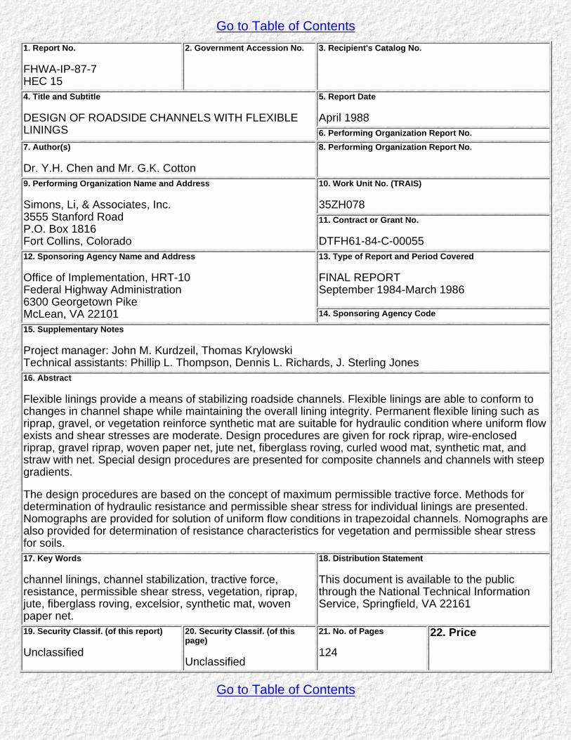
Go to Table of Contents1. Report No.
FHWA-IP-87-7HEC 15
2. Government Accession No. 3. Recipient's Catalog No.
4. Title and Subtitle
DESIGN OF ROADSIDE CHANNELS WITH FLEXIBLELININGS
5. Report Date
April 19886. Performing Organization Report No.
7. Author(s)
Dr. Y.H. Chen and Mr. G.K. Cotton
8. Performing Organization Report No.
9. Performing Organization Name and Address
Simons, Li, & Associates, Inc.3555 Stanford RoadP.O. Box 1816Fort Collins, Colorado
10. Work Unit No. (TRAIS)
35ZH07811. Contract or Grant No.
DTFH61-84-C-0005512. Sponsoring Agency Name and Address
Office of Implementation, HRT-10Federal Highway Administration6300 Georgetown PikeMcLean, VA 22101
13. Type of Report and Period Covered
FINAL REPORTSeptember 1984-March 1986
14. Sponsoring Agency Code
15. Supplementary Notes
Project manager: John M. Kurdzeil, Thomas KrylowskiTechnical assistants: Phillip L. Thompson, Dennis L. Richards, J. Sterling Jones16. Abstract
Flexible linings provide a means of stabilizing roadside channels. Flexible linings are able to conform tochanges in channel shape while maintaining the overall lining integrity. Permanent flexible lining such asriprap, gravel, or vegetation reinforce synthetic mat are suitable for hydraulic condition where uniform flowexists and shear stresses are moderate. Design procedures are given for rock riprap, wire-enclosedriprap, gravel riprap, woven paper net, jute net, fiberglass roving, curled wood mat, synthetic mat, andstraw with net. Special design procedures are presented for composite channels and channels with steepgradients.
The design procedures are based on the concept of maximum permissible tractive force. Methods fordetermination of hydraulic resistance and permissible shear stress for individual linings are presented.Nomographs are provided for solution of uniform flow conditions in trapezoidal channels. Nomographs arealso provided for determination of resistance characteristics for vegetation and permissible shear stressfor soils.17. Key Words
channel linings, channel stabilization, tractive force,resistance, permissible shear stress, vegetation, riprap,jute, fiberglass roving, excelsior, synthetic mat, wovenpaper net.
18. Distribution Statement
This document is available to the publicthrough the National Technical InformationService, Springfield, VA 22161
19. Security Classif. (of this report)
Unclassified
20. Security Classif. (of thispage)
Unclassified
21. No. of Pages
124
22. Price
Go to Table of Contents
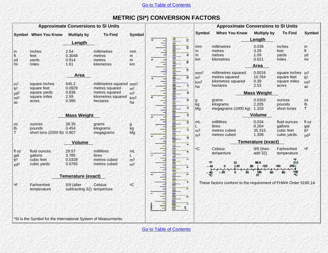
Go to Table of Contents
METRIC (SI*) CONVERSION FACTORSApproximate Conversions to SI Units
Symbol When You Know Multiply by To Find Symbol
Length
inftydmi
inchesfeetyardsmiles
2.540.30480.9141.61
millimetresmetresmetreskilometres
mmmmkm
Area
in2
ft2yd2
mi2ac
square inchessquare feetsquare yardssquare milesacres
645.20.09290.8362.590.395
millimetres squaredmetres squaredmetres squaredkilometres squaredhectares
mm2
m2
m2
km2ha
Mass Weight
ozlbT
ouncespoundsshort tons (2000 lb)
28.350.4540.907
gramskilogramsmegagrams
gkgMg
Volume
fl ozgalft3yd3
fluid ouncesgallonscubic feetcubic yards
29.573.7850.03280.0765
millilitreslitresmetres cubedmetres cubed
mLLm3
m3
Temerature (exact) oF Farhrenheit
temperature5/9 (aftersubtracting 32)
Celsiustemperture
oC
*SI is the Symbol for the International System of Measurments
Approximate Conversions to SI UnitsSymbol When You Know Multiply by To Find Symbol
Length mmmmkm
millimetresmetresmetreskilometres
0.0393.281.090.621
inchesfeetyardsmiles
inftydmi
Area mm2
m2
km2ha
millimetres squaredmetres squaredkilometres squaredhectares
0.001610.7640.392.53
square inchessquare feetsquare milesacres
in2
ft2mi2ac
Mass Weight gkgMg
gramskilogramsmegagrams (1000 kg)
0.03532.2051.103
ouncespoundsshort tones
ozlbT
Volume mLLm3
m3
millilitreslitresmetres cubedmetres cubed
0.0340.26435.3151.308
fluid ouncesgallonscubic feetcubic yards
fl ozgalft3yd3
Temerature (exact) oC Celsius
temperture9/5 (thenadd 32)
Farhrenheittemperature
oF
These factors conform to the requirement of FHWA Order 5190.1A
Go to Table of Contents
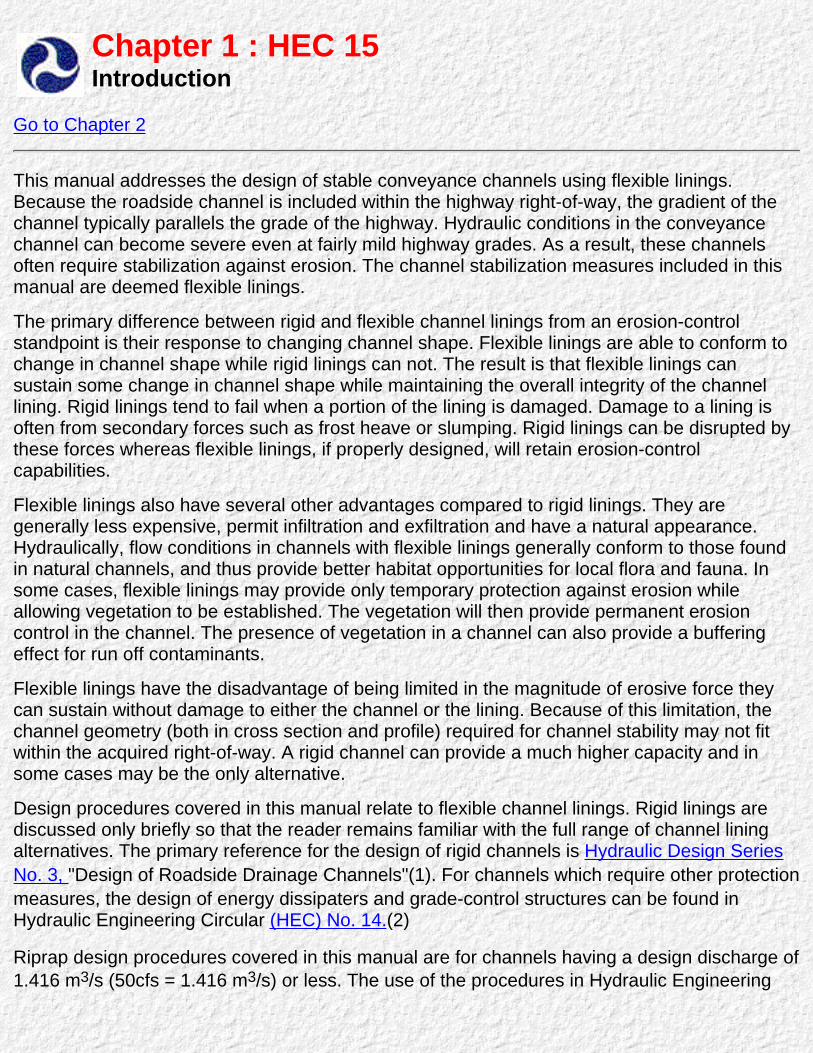
Chapter 1 : HEC 15Introduction
Go to Chapter 2
This manual addresses the design of stable conveyance channels using flexible linings.Because the roadside channel is included within the highway right-of-way, the gradient of thechannel typically parallels the grade of the highway. Hydraulic conditions in the conveyancechannel can become severe even at fairly mild highway grades. As a result, these channelsoften require stabilization against erosion. The channel stabilization measures included in thismanual are deemed flexible linings.
The primary difference between rigid and flexible channel linings from an erosion-controlstandpoint is their response to changing channel shape. Flexible linings are able to conform tochange in channel shape while rigid linings can not. The result is that flexible linings cansustain some change in channel shape while maintaining the overall integrity of the channellining. Rigid linings tend to fail when a portion of the lining is damaged. Damage to a lining isoften from secondary forces such as frost heave or slumping. Rigid linings can be disrupted bythese forces whereas flexible linings, if properly designed, will retain erosion-controlcapabilities.
Flexible linings also have several other advantages compared to rigid linings. They aregenerally less expensive, permit infiltration and exfiltration and have a natural appearance.Hydraulically, flow conditions in channels with flexible linings generally conform to those foundin natural channels, and thus provide better habitat opportunities for local flora and fauna. Insome cases, flexible linings may provide only temporary protection against erosion whileallowing vegetation to be established. The vegetation will then provide permanent erosioncontrol in the channel. The presence of vegetation in a channel can also provide a bufferingeffect for run off contaminants.
Flexible linings have the disadvantage of being limited in the magnitude of erosive force theycan sustain without damage to either the channel or the lining. Because of this limitation, thechannel geometry (both in cross section and profile) required for channel stability may not fitwithin the acquired right-of-way. A rigid channel can provide a much higher capacity and insome cases may be the only alternative.
Design procedures covered in this manual relate to flexible channel linings. Rigid linings arediscussed only briefly so that the reader remains familiar with the full range of channel liningalternatives. The primary reference for the design of rigid channels is Hydraulic Design SeriesNo. 3, "Design of Roadside Drainage Channels"(1). For channels which require other protectionmeasures, the design of energy dissipaters and grade-control structures can be found inHydraulic Engineering Circular (HEC) No. 14.(2)
Riprap design procedures covered in this manual are for channels having a design discharge of1.416 m3/s (50cfs = 1.416 m3/s) or less. The use of the procedures in Hydraulic Engineering

Circular (HEC) No. 11 is recommended for the design of riprap revetments or linings onchannels and streams with design flows in excess of 1.416 m3/s(3).
The permissible tractive force and Manning n values provided in this manual for grass linedchannels cannot be compared to values found in earlier manuals. The current values are basedon research conducted at Colorado State University which takes into account the stiffness ofthe vegetation.
The riprap procedure for steep channels is based on an analysis of forces acting on the riprap.While this procedure is theoretically sound, the results should be used with caution and betaken as guidance. Whenever possible, the procedure should be checked against theperformance of installed channels in the field. The steep slope design procedure is limited tochannels having a design discharge of 1.416 m3/s of less.
Go to Chapter 2

References
1. Federal Highway Administration,Bureau of Public Roads"Design of Roadside Drainage Channels."Hydraulic Design Series No. 3, Hydraulics Branch, 1965.
2. Federal Highway Administration,"Hydraulic Design of Energy Dissipators for Culverts and Channels."Hydraulic Engineering Circular No. 14, Hydraulics Branch, 1983.
3. Federal Highway Administration,"Use of Riprap for Bank Protection."Hydraulic Engineering Circular No. 11, 1987.
4. Soil Conservation Service,"Handbook of Channel Design for Soil and Water Conservation."SCS-TP-61, Stillwater, Oklahoma, 1954.
5. N. Kouwen, R.M. Li, and D.B. Simons,"Velocity Measurements in a Channel Lined with Flexible Plastic Roughness Elements."Technical Report No. CER79-80-RML-DBS-11, Department of Civil Engineering, Colorado State University, FortCollins, Colorado, 1980.
6. N. Kouwen, T.E. Unny, and H.M. Hill,"Flow Retardance in Vegetated Channel."J. Irrigation and Drainage Division, IRE, 1969, pp. 329-342.
7. V.T. Chow,"Open Channel Hydraulics."New York, Company, 1959. McGraw-Hill Book
8. A.G. Anderson, A.A. Painta, and J.T. Davenport,"Tentative Design Procedure for Riprap Lined Channels."NCHRP Report No. 108, Highway Research Board, National Academy of Sciences, Washington, D.C., 1970.
9. U.S. Bureau of Reclamation,Stable Channel Profiles.Lab. Report No. Hyd. 325, September 27, 1951.
10. O.J. Olsen and Q.L. Florey,"Sedimentation Studies in Open Channels Boundary Shear and Velocity Distribution by Membrane Analogy,Analytical and Finite-Difference Methods."Reviewed by D. McHenry and R.E. Clover, U.S. Bureau of Reclamation, Laboratory Report N. SP-34, August 5,1952.
11. M.A. Nouh and R.D. Townsend,"Shear Stress Distribution in Stable Channel Bends."Journal of the Hydraulics Division, ASCE, Vol. 105, No. HY10, Proc. Paper 14598, October, 1979, pp. 1233-1245.
12. E. Lane,"Design of Stable Channels,"Transactions ASCE, Vol. 120, 1955.
13. R.L. Cox, R.C. Adams, and T.B. Lawson,"Erosion Control Study, Part II, Roadside Channels."Louisiana Department of Highways, in Cooperation with U.S. Department of Transportation, Federal HighwayAdministration, 1971.

14. J.C. McWhorter, T.G. Carpenter, and R.N. Clark,"Erosion Control Criteria for Drainage Channels."Conducted for Mississippi State Highway Department in Cooperation with U.S. Department of Transportation,Federal Highway Administration, by the Agricultural and Biological Engineering Department,Agricultural Experiment Station, Mississippi State University, State College, Mississippi, 1968.
15. K.G. Thibodeaux,"Performance of Temporary Ditch Linings."Iterim Reports 1 to 17, Prepared for Federal Highway Administration by U.S. Geological Survey, Gulf CoastHydroscience Center and Computer Science Corporation, 1982 to 1985.
16. E.T. Smerdon and R.P. Beaseley,"The Tractive Force Theory Applied to Stability of Open Channels in Cohesive Soils."Agricultural Experiment Station, Research Bulletin No. 715, University of Missouri, Columbia, Missouri, October1959.
17. B.M. Galloway,"Pavement and Geometric Design Criteria for Minimizing Hydroplaning."Texas Transportation Institute, Texas A&M University, Federal Highway Administration, Report No. FHWA-RD-30,December 1979.
18. "Geotextile Engineering Manual,Course Text, FHWA, 1985.
19. J.C. Blodgett and C.E. McConaughy,"Evaluation of Design Practices for Rock Riprap Protection of Channels near Highway Structures."U.S. Geological Survey, Prepared in Cooperation with the Federal Highway Administration Preliminary Draft,Sacramento, California, 1985.
20. J.C. Bathurst, R.M. Li, and D.B. Simons,"Resistance Equation for Large-Scale Roughness."Journal of the Hydraulics Division, ASCE, Vol. 107, No. HY12, Proc. Paper 14239, December 198-1, pp. 1593-1613.
21. D.B. Simons and F. Senturk,Sediment Transport TechnologyFort Collins. Colorado: Water Resources Publications, 19 m .
22. S.Y. Wang and H.W. Shen,"Incipient Sediment Motion and Riprap Design."Journal of Hydraulics Division, ASCE, Vol. 111, No. 3, March 1985, pp. 52-538.
23. "Hydraulic Analysis and Design of Open Channels,"Highway Drainage Guidelines, Volume VI, American Association of State Highway Officials, 1982.

Symbols
A, B, C, D, F, G, H, K, L, M, N, P, Q, R, S, T, V, W, Y, Z, Misc.
To jump to a specific part of the alphabet, click on the above HotLinks!Click the Back button to return to the top of this page.(If the letter you are looking for does not appear in the HotLink list below, then there areno glossary entries for that letter!)
A
A= Cross-sectional area of flow prism. ft.2, M2.
AOS= Measure of the largest effective opening in a geotextile; representsopening size for which 95 percent of fabric pores are smaller than diameter.
B
B = Bottom width of trapezoidal channel, ft., m.
c
CG= Channel Geometry.
D
D50, D85 = Particle size of gradation, of which 50 percent, 85 percent, etc..,of the mixture is finer by weight, ft., m.
d = Depth of flow in channel, ft., m.
d = Change in depth due to super elevation of flow in a bend, ft., m.
dn = Depth of normal or uniform flow, ft., m.
F
Fd = Drag force in direction of flow.
Fl = lift force.
Fr = Froude number, ratio of inertial forces to gravatational force in a system.
G
g = gravitational acceleration, ft./sec.2, m/s2.
H
h = Average height of vegetation, ft., cm.

K
Kb = ratio of maximum shear stress in bend to maximum shear stress upstreamfrom bend.
KC = compound channel lining factor.
K1 = ratio of channel side shear to bottom shear stress.
K2 = tractive force ratio.
Ks = roughness height, ft., cm.
KS = Tractive force ratio at bottom of channel.
L
Lp = protected length downstream from bend, ft., m.
M
MEI = Stiffness factor, lb. x ft.2, Newton x m2.
N
n = Manning's flow roughness coefficient.
P
p = Wetted perimeter of flow prism, ft., m.
P = Wetted perimeter of low-flow channel, ft., m.
P.C. = Point on curve.
P.T. = Point on Tangent.
Q
Q = Discharge, flow rate, ft.3/sec., m3/s.
R
R = Hydraulic radius, A/P, ft. m.
RC = Mean radius of channel center line, ft., m.
REG = Roughness Element Gradient.
S
S = Average channel gradient.
Sf = Energy gradient.
SF = Safety factor
S50 = Mean of the short axis lengths of the distribution of roughness element.
SSF = Side Slope Factor.
T
T = Channel top width, ft., m.
V
V = Mean Channel Velocity, ft./sec., m/s.
V* = Shear Velocity, ft./sec., m/s.
W
WS = Weight of riprap element, lb. kg
Y
Y50 = Mean value of the distribution of the average of the long and medianaxes of a roughness element.
Z
Z = Side slope; cotangent of angle measured from horizontal.Z= cot φ
Misc.
= Moment arms of riprap channel.
α= Angles between weight vector and the resultant in the plane of the side slope.
β= Angle of repose of coarse, noncohesive material, degrees.
γ = Unit Weight of water, lb./ft.3, kg/m3
δ= Angle between the drag vector and resultant in the plane of the side slope.
θ = Angle of repose of coarse, noncohesive material, degrees.
η =Stability number
η' = Stability number for side slopes.
σ = Bed material gradation.
τ = Average shear stress, lb./ft.2, Kg/m2.

τb = Shear stress in a bend, lb./ft.2, Kg/m2.
τd = Shear stress in channel at maximum depth, lb./ft.2, kg/m2.
τp = Permissible shear stress, lb./ft.2, kg/m2.
τs = Shear stress on sides of channel, lb./ft.2, kg/m2.
φ= Angle of side slope (bank) measured from horizontal.