Design for Nano-Robots Exposing Cancer Cells -...
13
Design for Nano-Robots Exposing Cancer Cells by Shlomi Dolev, Michael Rosenblit and Ram Prasadh Narayanan Technical Report #18-02 May 08, 2018 The Lynne and William Frankel Center for Computer Science, Department of Computer Science, Ben-Gurion University, Beer Sheva, Israel.
Transcript of Design for Nano-Robots Exposing Cancer Cells -...
Design for Nano-Robots Exposing Cancer Cells
by
Shlomi Dolev, Michael Rosenblit and Ram Prasadh Narayanan
Technical Report #18-02
May 08, 2018
The Lynne and William Frankel Center for Computer Science,
Department of Computer Science,
Ben-Gurion University, Beer Sheva, Israel.
Design for Nano-Robots Exposing Cancer Cells
(Preliminary Version)
Shlomi Dolev1, Michael Rosenblit2 and Ram Prasadh Narayanan1
1Department of Computer Science, Ben-Gurion University of the Negev. Email:dolev,[email protected]
2Ilse Katz Institute of Nano-Scale Science and Technology, Ben-Gurion University of theNegev. Email: [email protected]
May 8, 2018
Abstract
A proof-of-concept design of a nano-robot which can navigate, detect cancer cells and actuatethe release of chemicals in blood is discussed. The nano-robot is designed with blood energyharvesting capability and accumulation of electricity in a capacitor, that forms the main body ofthe nano-robot. The nano-robot is immobilized with glucose hunger-based cancer detectors thatreduce the electrical resistance of a nano-tube when attached to a cancer cell. This mechanism,in turn allows electric current to activate a nano-electrical-mechanical (NEM) relay (mechanicaltransistor) to break the ceiling, exposing a chemical material identified by the immune system forcell elimination. This concept is in line with the effort to design an autonomous computationalnano-robot for in-vivo medical diagnosis and treatment. The concept can also be considered as astep to bridge the gap between theoretical swarming/navigation techniques and a computationalhardware for plausible implementation of the theory.
1 Introduction
In general, programmable matter is any matter that has the ability to change its physical prop-erties (like shape, density, moduli, conductivity, optical properties, etc.) based on user inputor autonomous sensing. We are particularly interested in implementable programmable mattercomposed of nano-robots. Advances in electronic fabrication satisfies the necessity of resourceadequacy in nano computational systems and the implementation feasibility of particle systemsmake it possible to incorporate nano-computational systems into materials used in paint coating,structural integrity, vibration sensors etc. [1]. Recent advances in controlling mechanisms in bio-logical systems, such as cell signaling, cell movement and nano delivery devices for area focusedtreatment [2–5], motivate the need for further research in these areas. Models for programmablematter exist in computational geometry [6–10], synthetic biology [11–13], swarm robotics [14–18]and distributed computing [19, 20]. But most of these fields have focused on obtaining theoreticalresults rather than a possible implementation.
Nano-robotics is a rapidly growing interdisciplinary field addressing the assembly and utiliza-tion of molecular devices based on nano-scale principles [21]. Key applications to nano-roboticsare medical target identification, targeted drug delivery and minimal invasive surgery [22–24], toname a few. In our previous work [25], we presented a swarming algorithm for in-vivo nano-robots,
1
inspired by caterpillar swarm in nature, wherein the nano-robots were considered as large quan-tities of programmable matter. We suggested instructing the computational particles to createlayered and connected structures for the benefit of speed and energy preservation. We put for-ward a proposition, that the theoretical concept needs to be supported by hardware feasibility fora plausible implementation of a computational nano-robot. Through this work, we have attemptedto design autonomous nano-robots which can harvest energy from the glucose in the blood andactivate a response, based on bio-detection. We will present below the design of the nano-robotstructure with three modules, (i) External coated energy harvester electrodes and cylindrical ca-pacitor, (ii) Detector and (iii) Actuator. We believe this facile theory of inorganic nano-robotplatform design can help to bridge the gap between existing research on bio-nano sensing in com-bination with advanced nano transistor technology towards cancer treatment. A collective systemof electrical manipulation, bio-detection and NEM actuation can visualize the programmability inthe nano matters.
2 Design of Nano-Robot Structure
2.1 Energy harvester and Metal-Insulator-Metal (M-I-M) cylindrical nano-capacitor
A nano-robot can be termed autonomous if there is no dependency on external sources for its oper-ation. The first step to visualizing an autonomous nano-robot is to provide an energy source to it.Thus, as a first module, we wanted to show that autonomy can be introduced to the nano-robot byharvesting energy from the blood. In references [26–28], inorganic glucose energy harvesters werefabricated and analyzed for their efficiency. Certain inorganic materials, like platinum, grapheneetc., are used as electrodes due to their bio-compatibility and tested usage scenarios [27, 29, 30].An open circuit voltage, Voc of 192−860 mV , was reported from glucose fuel cells in [26, 28]. Next,we detail our estimation of capacitance of a cylindrical capacitor based on properties of blood, inparticular, its glucose concentration.
At injection, the nano-robots are under constant influence of the blood. The velocity of bloodflow ranges from 0.3 − 40 cm/sec [31]. The total surface area of the anode in the cylindricalnano-robot is given by
πr2 + 2πrh = (π × 502) + (2π × 50× 40)
= 2.041× 10⁻¹⁰cm2
where, 50nm and 40nm is the radius and height of the anode, respectively. With the displacementof 0.3− 40 cm, volume of blood interacting with the nano-robot per second is equal to the surfacearea of the nano-robot multiplied by the blood velocity1:
(2.041× 10−10 × 0.3)↔ (2.041× 10−10 × 40)
= (6.123↔ 816.4)× 10−14L/Sec
Glucose concentration in the human blood is (3.9− 6.4) mM/L. On average, if 5.5 mM/L is theconcentration of glucose, the number of moles of glucose interacting with the nano-robot is givenas the product of concentration of glucose in blood and the volume of blood interacting with thenano-robot, as: (
(6.123× 5.5)↔ (816.4× 5.5)
)× 10−14
= (33.67↔ 4490.2)× 10−14mM/Sec
1The ↔ in the equations indicate ‘to’, as ‘value A to value B’
2
The avagardo’s constant is given by 6.023× 10²³. Thus the number of molecules of glucose in theinteracting volume of blood is given as:(
(33.67× 6.023)↔ (4490.2× 6.023)
)× 10−14 × 1023
= 20.2↔ 2704.4× 1010Molecules
As stated in references [26, 28], abiotic glucose oxidation liberates maximum of 2 electrons perglucose molecule. Thus, the number of electrons in the interacting molecules is given by:(
2× (20.2↔ 2704.4)× 1010)
= (40.4↔ 5408.8)× 1010Electrons/Sec
Thus, the source current of the harvester is calculated to be the product of number of electronsand charge per 1 electron:
(40.4× 1010 × 1.6× 10−19)↔ (5408.8× 1010 × 1.6× 10−19)
= (64.64↔ 8654)nA
Maximum charge stored in the capacitor is given by
Qmax = C/Voc
C =ε0εrA
d
where A is the surface area of the capacitive plate and d is the thickness of dielectric. The totalsurface area available for the capacitor is given as:
A = 2πr1h+ 2πr2h+ 2πr3h = 2πh(r1 + r2 + r3)
2π × 80nm(41 + 30 + 19) = 45216nm2 = 4.52× 10⁻¹⁴m2
where, r1, r2, r3 are the radius of concentric cylinders in the capacitor as shown in 1. Thus,the capacitance calculated for the surface area and with quartz dielectric (relative permittivityεr = 4.7 and conductance σ = 10−14S/m) is:
C =8.854× 10−12 × 4.7× 4.52× 10−14
4× 10−9= 4.702× 10⁻¹⁶F
Qmax = C/Voc = 2.449pC
The charging time of the capacitor is given by fraction of maximum charge storage to the generatedcharge per second:(
2.449× 10⁻¹²/8654× 10−9)↔
(2.449× 10⁻¹²/64.64× 10−9
)= 0.3↔ 38µSec
Variation in charging time is proportional to the velocity of the blood flow and the total surfacearea of the anode in the cylindrical nano-robot.
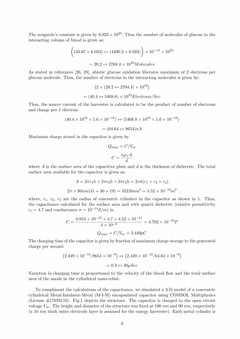
To compliment the calculations of the capacitance, we simulated a 3-D model of a concentriccylindrical Metal-Insulator-Metal (M-I-M) encapsulated capacitor using COMSOL Multiphysics(License #17076110). Fig.1 depicts the structure. The capacitor is charged to the open circuitvoltage Voc. The height and diameter of the structure was fixed at 100 nm and 90 nm, respectively(a 10 nm thick outer electrode layer is assumed for the energy harvester). Each metal cylinder is
3
(a) (b)
Figure 1: (a) Structure of concentric cylindrical capacitor (b) The electric field strength in thedielectric and air domain surrounding the capacitor (green arrows perpendicular to the z-axis)
10 nm in thickness. Four metal cylinders are arranged concentrically (inside each other) with 4nm thick dielectric layers separating them. The alternate metal cylinders are imagined extendingoutside along the vertical axis at the extremes to differentiate positive and negative cylinders con-nected to respective electrodes of the harvester. This design was chosen to increase the surfacearea of the capacitor, eventually improving the capacitance. The structure was designed withquartz dielectric (εr = 4.7 and σ = 10−14S/m). Appropriate boundary conditions were applied atthe interface of air/dielectric in alternate discs. The capacitance of the device was computed tobe 4.326× 10⁻¹⁶ F . Thus, the analyzed and simulated capacitance were nearly equal.
The simulated structure is precisely maintained within a 100nm dimension to (i) Qualify thestructure as a nano-robot, (ii) To allow the nano-robot to immobilize itself on the cell surfaceand act as a parasite. The provided energy harvesting capability will enhance the nano-robot topower, in particular, the detector to be used for actuation.
2.2 Bio-Detector
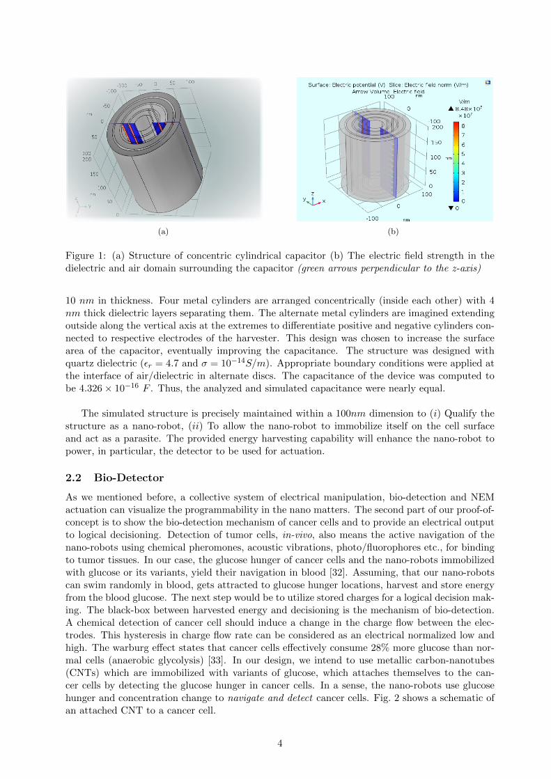
As we mentioned before, a collective system of electrical manipulation, bio-detection and NEMactuation can visualize the programmability in the nano matters. The second part of our proof-of-concept is to show the bio-detection mechanism of cancer cells and to provide an electrical outputto logical decisioning. Detection of tumor cells, in-vivo, also means the active navigation of thenano-robots using chemical pheromones, acoustic vibrations, photo/fluorophores etc., for bindingto tumor tissues. In our case, the glucose hunger of cancer cells and the nano-robots immobilizedwith glucose or its variants, yield their navigation in blood [32]. Assuming, that our nano-robotscan swim randomly in blood, gets attracted to glucose hunger locations, harvest and store energyfrom the blood glucose. The next step would be to utilize stored charges for a logical decision mak-ing. The black-box between harvested energy and decisioning is the mechanism of bio-detection.A chemical detection of cancer cell should induce a change in the charge flow between the elec-trodes. This hysteresis in charge flow rate can be considered as an electrical normalized low andhigh. The warburg effect states that cancer cells effectively consume 28% more glucose than nor-mal cells (anaerobic glycolysis) [33]. In our design, we intend to use metallic carbon-nanotubes(CNTs) which are immobilized with variants of glucose, which attaches themselves to the can-cer cells by detecting the glucose hunger in cancer cells. In a sense, the nano-robots use glucosehunger and concentration change to navigate and detect cancer cells. Fig. 2 shows a schematic ofan attached CNT to a cancer cell.
4
Figure 2: Schematic (not in scale) of a cancer cell attached to a drug supported CNT platform
CNTs can be used as channel materials due to their tunable electrical parameters, mechan-ical stability, ballistic transport and high current carrying ability. Theoretical calculations andmeasurements prove that the ballistic transport2 and mean free path of electron transfer in CNTsextend to over 1µm [34]. Single walled CNTs (SWCNT) have been tested for their use as bio-detectors. The most important requirement for a CNT bio-sensor is the electrical conductivity ofthe device as it directly defines the bio-detection capability of the CNTs. Enzyme-coated SWCNTsreferred here [35] showed strong pH dependence, wherein the conductance of bare CNTs reducedwith glucose immobilization and increased by over 10% when glucose molecules were added tothem, suggesting their use for glucose hunger and bio-detection.
The conductance of the immobilized glucose hunger detector before and after detection is givenas:
Before glucose hunger detection: ≈ 2.4 µS
R =1
2.4µS= 0.42MΩ
After glucose hunger detection: ≈ 2.7 µS (≈ 10% increase)
R =1
2.7µS= 0.37MΩ
Estimated time constant of the signal (before detection):
τ = RC = 0.42× 106 × 4.326× 10−16 = 182pS(pico)
Estimated time constant of the signal (after detection):
τ = RC = 0.37× 106 × 4.326× 10−16 = 160pS(pico)
Any capacitor discharges within 5τ [36]. In this case, if Voc is assumed to be ≈ 200mV , ≈ 1.2τwill be the estimated time until which operable voltage and current is supplied to the actuator,when no current leakage exists. Later, we show that the current leakage implies doubling the timeconstant values. We tune up the design of the detector so that the change in conductance, beforeand after immobilization, can be attributed to the capacitance change of the CNT. Likewise, work
2Transport of electrons from one end to another without loss of energy inside the medium, i.e, the electrons travelinside the medium as a ballistic missile.
5
in [37, 38] describes the capture of breast cancer cell lines on CNT arrays. The change in specificconductance of the CNT was considered as the electrical signature for detection of the cancer cellsspiked on the blood sample. Different combinations of anti-bodies and cancer cell lines were testedto know the best combination which provides higher conductance change. All the above presenteddata portrays CNTs as excellent materials for applications demanding higher conductivity, currentcarrying capacity, ballistic electron transport and bio-detection. We are aware of the quantumeffects in CNT devices [39] which would be also considered when the design is elaborated.
2.3 Actuator
Until this stage, the concept is extended to the point where the nano-robots are autonomous interms of their power and navigation, and computationally equipped to handle a bit change ofinformation. Programmable matters are often imagined to express color changes for swarming,communication and other forms of actuation. In this section, we will discuss the possibility of aNano-Elecro-Mechanical (NEM) switch which gets triggered by the conductance change of immo-bilized CNT bio-detector. This will ensure that the matters will respond appropriately dependingon the decided logical operation. Miniature mechanical switches suitable for applications, whichrequire less than 100mV for operation, were demonstrated here [40, 41]. An MEM actuator switchwas demonstrated to operate with a minimum switching voltage of 80mV [40]. We have alreadyshown in subsection 2.1 that a cylindrical capacitor can harvest sufficient charges to provide anoperable voltage of 192 − 860 mV . In this section, we show that a mechanical chamber can bedesigned to lock necessary drug or a combination of drugs, that can be unlocked when increase inelectrical power flow due to bio-detection provides adequate electrostatic force to break the ceilingof the chamber, eventually exposing the drug to the environment. This setup can be synonymousto color change or fluorescent marking of a programmable matter. In this regard, we calculatedand simulated a NEM actuator which can be broken. Within a unit time constant τ = RC, whereR is the resistance and C is the capacitance of the energy harvester, the operating voltage suppliedfrom the energy harvester is expected to drop from 200mV to 70mV . This discharge (until ≈ 1τ)can be utilized to provide operable current and voltage for the NEM device actuation. This signalis expected to cause a mechanical break, high enough to surpass the stress gradient of the ceilingstructure in the actuator. The mechanical break exposes a detectable drug causing the immunesystem to recognize the attached nano-robot and the cancer cell. We can also consider the NEMactuator as a parallel plate capacitor. Hence, the electrostatic force Fe acting on the parallel platesdue to change in dielectric thickness is given by
Fb = Fe =1
2V 2b
εAcd2
(1)
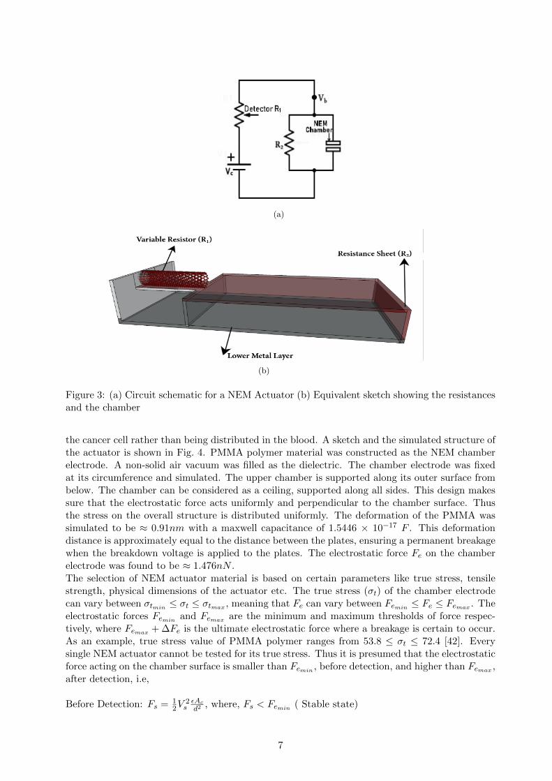
where Vb and Fb are the breakdown voltage and force of the NEM chamber with the glued druginside it, Ac is the area of the ceiling, and d is the distance between the plates. Fig. 3 showsthe circuit schematic and its equivalent sketch of the chamber. The resistances R1 and R2 tunethe breakdown voltage Vb, such that the NEM chamber collapses. With increase in Vb (due toresistance change after detection), Fe is increased to reach Fb, the force required to trigger a per-manent breakage. Before detection, there is leakage of current from the energy harvester to theactuator. Since we consider the actuator as parallel capacitive plates, the capacitance increasesin the plates until the capacitor is full. On the other hand, the discharge also happens throughthe resistor R2( 3b). Thus the value of R2 has to be maintained, such that, the discharge is lesserthan the charging rate and at the same time, the charge-discharge rate of the actuator capacitoris higher and lesser than the charging time of the energy harvester before and after detection,respectively. This ensures that the actuator would not actuate to a false high signal.
An increase in input voltage, Vin due to detection, will result in the breakage of NEM box (whenVin reaches Vb), thus exposing the glued drug. The drug is glued to keep the target associated with
6
(a)
(b)
Figure 3: (a) Circuit schematic for a NEM Actuator (b) Equivalent sketch showing the resistancesand the chamber
the cancer cell rather than being distributed in the blood. A sketch and the simulated structure ofthe actuator is shown in Fig. 4. PMMA polymer material was constructed as the NEM chamberelectrode. A non-solid air vacuum was filled as the dielectric. The chamber electrode was fixedat its circumference and simulated. The upper chamber is supported along its outer surface frombelow. The chamber can be considered as a ceiling, supported along all sides. This design makessure that the electrostatic force acts uniformly and perpendicular to the chamber surface. Thusthe stress on the overall structure is distributed uniformly. The deformation of the PMMA wassimulated to be ≈ 0.91nm with a maxwell capacitance of 1.5446 × 10⁻¹⁷ F . This deformationdistance is approximately equal to the distance between the plates, ensuring a permanent breakagewhen the breakdown voltage is applied to the plates. The electrostatic force Fe on the chamberelectrode was found to be ≈ 1.476nN .The selection of NEM actuator material is based on certain parameters like true stress, tensilestrength, physical dimensions of the actuator etc. The true stress (σt) of the chamber electrodecan vary between σtmin ≤ σt ≤ σtmax , meaning that Fe can vary between Femin ≤ Fe ≤ Femax . Theelectrostatic forces Femin and Femax are the minimum and maximum thresholds of force respec-tively, where Femax + ∆Fe is the ultimate electrostatic force where a breakage is certain to occur.As an example, true stress value of PMMA polymer ranges from 53.8 ≤ σt ≤ 72.4 [42]. Everysingle NEM actuator cannot be tested for its true stress. Thus it is presumed that the electrostaticforce acting on the chamber surface is smaller than Femin , before detection, and higher than Femax ,after detection, i.e,
Before Detection: Fs = 12V
2sεAcd2
, where, Fs < Femin ( Stable state)
7
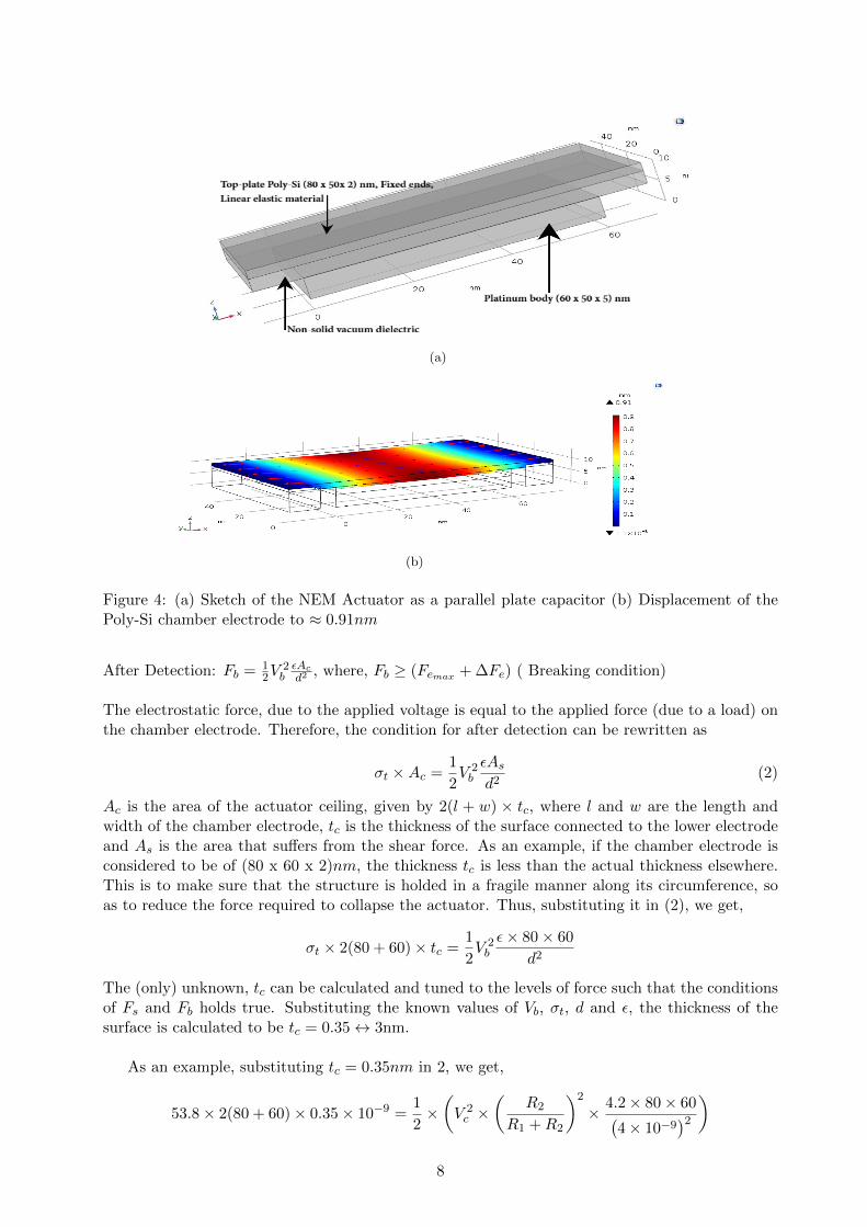
(a)
(b)
Figure 4: (a) Sketch of the NEM Actuator as a parallel plate capacitor (b) Displacement of thePoly-Si chamber electrode to ≈ 0.91nm
After Detection: Fb = 12V
2bεAcd2
, where, Fb ≥ (Femax + ∆Fe) ( Breaking condition)
The electrostatic force, due to the applied voltage is equal to the applied force (due to a load) onthe chamber electrode. Therefore, the condition for after detection can be rewritten as
σt ×Ac =1
2V 2b
εAsd2
(2)
Ac is the area of the actuator ceiling, given by 2(l + w) × tc, where l and w are the length andwidth of the chamber electrode, tc is the thickness of the surface connected to the lower electrodeand As is the area that suffers from the shear force. As an example, if the chamber electrode isconsidered to be of (80 x 60 x 2)nm, the thickness tc is less than the actual thickness elsewhere.This is to make sure that the structure is holded in a fragile manner along its circumference, soas to reduce the force required to collapse the actuator. Thus, substituting it in (2), we get,
σt × 2(80 + 60)× tc =1
2V 2b
ε× 80× 60
d2
The (only) unknown, tc can be calculated and tuned to the levels of force such that the conditionsof Fs and Fb holds true. Substituting the known values of Vb, σt, d and ε, the thickness of thesurface is calculated to be tc = 0.35↔ 3nm.
As an example, substituting tc = 0.35nm in 2, we get,
53.8× 2(80 + 60)× 0.35× 10−9 =1
2×(V 2c ×
(R2
R1 +R2
)2
× 4.2× 80× 60(4× 10⁻⁹
)2 )
8
15064× 0.35× 10−9 = 2520× 10−16 ×(
R2
R1 +R2
)2
15064× 0.35× 10−9
2520× 10−16=
(R2
R1 +R2
)2
20.92× 106 =
(R2
R1 +R2
)2
4.573× 103 =
(R2
R1 +R2
)4.573× 10³ × (R1 +R2) = R2
solving which we get R2 to be ≈ 0.4MΩ. Substituting tc = 3nm, we get approximately the samevalue for R2.
53.8× 2(80 + 60)× 3× 10−9 =1
2×(V 2c ×
(R2
R1 +R2
)2
× 4.2× 80× 60(4× 10⁻⁹
)2 )
15064× 3× 10−9 = 2520× 10−16 ×(
R2
R1 +R2
)2
15064× 3× 10−9
2520× 10−16=
(R2
R1 +R2
)2
179.33× 106 =
(R2
R1 +R2
)2
13.39× 103 =
(R2
R1 +R2
)13.39× 10³ × (R1 +R2) = R2
solving which, we get R2 to be ≈ 0.4MΩ.
Once the applied voltage reaches Vb, the relay becomes unstable, thus resulting in a permanentbreakage. We have also modeled the structure in Fig. 3a for its circuit parameters. The NEMactuator can also be considered as a single shell (the resistor and capacitor) and an externalresistor, connected to a supply voltage. The current Ia through the actuator is given by
Ia =Vc
R1 +R2
Vb = Vc.R2
R1 +R2= IaR2
where, Vc is the supply voltage to the actuator, Vb is the breakdown voltage, R1 is the detectorCNT and R2 is the sheet resistance. The current Ia is given by:
Ia =200mV
0.42MΩ= 0.476µA (before detection)
Ia =200mV
0.37MΩ= 0.540µA (after detection, ≈ 11% increase in current flow)
At the same time instance, a current Il is depleted through R2, given by:
Il =Vc
R1 +R2
9
Il =200mV
0.4MΩ + 0.4MΩ= 0.25µA
The leakage current is lesser than (half) the actuator current which in turn implies doubling thetime needed to charge the actuator, i.e, doubling the time estimated in Section 2.2, before andafter detection.
3 Conclusion and future work
A facile approach of an energy harvester, glucose hunger detector for cancer cells and actuator fordrug exposure design is discussed. A collective system of electrical manipulation, bio-detection andNEM actuation to visualize the programmability in nano-robots is presented. The calculations andsimulation results provide a proof-of-concept towards a plausible implementation of an autonomouscomputational nano-robot with bio-detection, logical decisioning and actuation for drug exposure.To the best of our knowledge, this work is the first of its kind that presents an overall picturetowards an autonomous computational nano-robot for cancer diagnosis and treatment.
Acknowledgements
We thank the Lynne and William Frankel Center for Computer Science, the Rita Altura TrustChair in Computer Science, the Krietman School of Advanced Graduate Studies, Ben-GurionUniversity of the Negev for their support to this work. We also thank Prof. Zeev Zalevsky fromBar-Ilan University for his useful comments and assistance.
10
References
[1] H. Abelson, D. Allen, D. Coore, C. Hanson, G. Homsy, Jr. T.F. Knight, R. Nagpal, E. Rauch, G. J. Sussman,and R. Weiss. Amorphous computing. Commun. ACM, 43(5):74–82, May 2000.
[2] Wikipedia, cell signaling. https://en.wikipedia.org/wiki/Cell_signaling.[3] R. Ananthakrishnan and A. Ehrlicher. The forces behind cell movement. International Journal of Biological
Sciences, 3:303–307, 2007.[4] D. Dolmans, D. Fukumura, and R.K. Jain. Photodynamic therapy for cancer. Nature Reviews:Cancer, 3(8):380
– 387, 2003.[5] S. B. Brown, E. A. Brown, and I. Walker. The present and future role of photodynamic therapy in cancer
treatment. Elsevier, The Lancet Oncology, 5(8):497 – 508, 2004.[6] K. C. Cheung, E. D. Demaine, J. R. Bachrach, , and S. Griffith. Programmable assembly with universally
foldable strings (moteins). Trans. Robotics, 27:718–729, 2011.[7] C. Moya, X. Doris, and W. Damien. Parallel computation using active self-assembly. 19th International
Conference on DNA Computing and Molecular Programming, pages 16–30, 2013.[8] E. Demaine and T. Tachi. Origamizer: A practical algorithm for folding any polyhedron. In In 33rd Intl.
Symposium on Computational Geometry, pages 34:1–34:16, 2017.[9] Y. J. Chen, B. Groves, R. A. Muscat, and G. Seelig. Dna nanotechnology from the test tube to the cell. Nature
Nanotechnology – Review, 10:748–760, 2015.[10] Y. Amir, E. Ben-Ishay, D. Levner, S. Ittah, A. Abu-Horowitz, and I. Bachelet. Universal computing by dna
origami robots in a living animal. Nature Nanotechnology – Letters, 9:353–357, 2014.[11] Y. Benenson, T. Paz-Elizur, R. Adar, E. Keinan, Z. Livneh, and E. Shapiro. Programmable and autonomous
computing machine made of biomolecules. Nature, 414:430–434, 2001.[12] Ramiz Daniel, Jacob Rubens, Rahul Sarpeshkar, and Tomothy K. Lu. Synthetic analog computation in living
cells. Nature, 497(7451):619–623, 2013.[13] Alec A. K. Nielsen, Bryan S. Der, Jonghyeon Shin, Prashant Vaidyanathan, Vanya Paralanov, Elizabeth A.
Strychalski, David Ross, Douglas Densmore, and Christopher A. Voigt. Genetic circuit design automation.Science, 352(6281), 2016.
[14] P. Flocchini, D. Ilcinkas, A. Pelc, and N. Santoro. Computing without communicating: Ring exploration byasynchronous oblivious robots. Algorithmica, 65(3):562–583, 2013.
[15] C. Agathangelou, C. Georgiou, and M. Mavronicolas. A distributed algorithm for gathering many fat mobilerobots in the plane. In Proc. of the 2013 ACM Symp. on Principles of Distributed Computing, pages 250–259,2013.
[16] M. Cieliebak, P. Flocchini, G. Prencipe, and N. Santoro. Distributed computing by mobile robots: Gathering.SIAM Journal on Computing, 41(4):829–879, 2012.
[17] P. Flocchini, G. Prencipe, N. Santoro, and P. Widmayer. Arbitrary pattern formation by asynchronous,anonymous, oblivious robots. Theoretical Computer Science, 407(1):412–447, 2008.
[18] M. Rubenstein, A. Cornejo, and R. Nagpal. Programmable self-assembly in a thousand-robot swarm. Science,345(6198):795–799, 2014.
[19] M. Drees, M. Hullmann, A. Koutsopoulos, and C. Scheideler. Self-organizing particle systems. In Proc. of the26th IEEE Intl. Parallel and Distributed Processing Symposium (IPDPS), 2012.
[20] F. Hurtado, E. Molina, S. Ramaswami, and V. Sacristan. Distributed reconfiguration of 2d lattice-basedmodular robotic systems. Autonomous Robots, 38(4):383–413, 2015.
[21] Aristides Requicha. Nanorobots, nems and nanoassembly. Proceedings of the IEEE, 91(11):1922–1933, 2003.[22] Wikipedia. Size of a human cell.[23] P. Rothemund. Folding dna to create nanoscale shapes and patterns. Nature, 440:297–302, 2006.[24] Carlo Montemagno and George Bachand. Constructing nanomechanical devices powered by biomolecular
motors. Nanotechnology, 10:225–231, 1999.[25] S. Dolev, S. Frenkel, M. Rosenblit, R. P. Narayanan, and K. M. Venkateswarlu. In-vivo energy harvesting nano
robots. In 2016 IEEE International Conference on the Science of Electrical Engineering (ICSEE), pages 1–5,Nov 2016.
[26] B. I. Rapoport, J. T. Kedzierski, and R. Sarpeshkar. A glucose fuel cell for implantable brainmachine interfaces.PLOS ONE, 7(6):1–14, 06 2012.
[27] M. Frei, J. Erben, J. Martin, R. Zengerle, and S. Kerzenmacher. Nanofiber-deposited porous platinum enablesglucose fuel cell anodes with high current density in body fluids. Journal of Power Sources, 362:168 – 173,2017.
[28] Kiichi Niitsu, Takashi Ando, Atsuki Kobayashi, and Kazuo Nakazato. Enhancement in open-circuit voltage ofimplantable cmos-compatible glucose fuel cell by improving the anodic catalyst. Japanese Journal of AppliedPhysics, 56(1S):01AH04, 2017.
[29] C. Khler, A. Kloke, A. Drzyzga, R. Zengerle, and S. Kerzenmacher. Fabrication of highly porous platinumelectrodes for micro-scale applications bypulsed electrodeposition and dealloying. Journal of Power Sources,242:255 – 263, 2013.
11
[30] S. Kerzenmacher, U. Krling, T. Metz, R. Zengerle, and F. von Stetten. A potentially implantable glucosefuel cell with raney-platinum film electrodes for improved hydrolytic and oxidative stability. Journal of PowerSources, 196(3):1264 – 1272, 2011.
[31] P D Stein and H N Sabbah. Turbulent Blood-Flow in Ascending Aorta of Humans with Normal and DiseasedAortic Valves. Circulation Research, 39(1):58–65, 1976.
[32] Sarah nano-particle. http://www.innovex.co.il/_Uploads/dbsAttachedFiles/
NewPhasePresentationframeiNNOVEX2016.pdf.[33] Maria V Liberti and Jason W Locasale. The warburg effect: how does it benefit cancer cells? Trends in
biochemical sciences, 41(3):211–218, 2016.[34] M. S. Purewal, B. H. Hong, A. Ravi, B. Chandra, J. Hone, and P. Kim. Scaling of resistance and electron
mean free path of single-walled carbon nanotubes. Phys. Rev. Lett., 98:186808, May 2007.[35] Koen Besteman, Jeong O. Lee, Frank G.M. Wiertz, Hendrik A. Heering, and Cees Dekker. Enzyme-coated
carbon nanotubes as single-molecule biosensors. Nano Letters, 3(6):727–730, 2003.[36] Capacitor charge/discharge. https://www.electronics-tutorials.ws/rc/rc_2.html.[37] F. Khosravi, P. J. Trainor, C. Lambert, G. Kloecker, E. Wickstrom, S. N. Rai, and B. Panchapakesan. Static
micro-array isolation, dynamic time series classification, capture and enumeration of spiked breast cancer cellsin blood: the nanotubectc chip. Nanotechnology, 27(44):44LT03, 2016.
[38] F. Khosravi, P. Trainor, S. N. Rai, G. Kloecker, E. Wickstrom, and B. Panchapakesan. Label-free captureof breast cancer cells spiked in buffy coats using carbon nanotube antibody micro-arrays. Nanotechnology,27(13):13LT02, 2016.
[39] Kazuyuki Uchida, Susumu Okada, Kenji Shiraishi, and Atsushi Oshiyama. Quantum effects in a double-walledcarbon nanotube capacitor. Physical review B, 76(15):155436, 2007.
[40] Chuang Qian, Alexis Peschot, Benjamin Osoba, Zhixin Alice Ye, and Tsu Jae King Liu. Sub-100 mV computingwith electro-mechanical relays. IEEE Transactions on Electron Devices, 64(3):1315–1321, 2017.
[41] B. Osoba, B. Saha, L. Dougherty, J. Edgington, C. Qian, F. Niroui, J. H. Lang, V. Bulovic, J. Wu, and T. J. K.Liu. Sub-50 mv nem relay operation enabled by self-assembled molecular coating. pages 26.8.1–26.8.4, Dec2016.
[42] Jurg Dual, Gerd Simons, Jurgen Villain, Jacaueline Vollmann, and Christina Weippert. Mechanical Propertiesof MEMS Structures. ICEM 12 - 12th International Conference on Experimental Mechanics, (March):8, 2004.
12


![Flying Robots - LentinkLab · Flying Robots Stefan Leutenegger, Christoph Huerzeler, Amanda K. Stowers, Kostas Alexis, ... hovering ornithopter at present, the Nano Humming-bird [32].](https://static.fdocuments.us/doc/165x107/5b1c07cb7f8b9a46258f4249/flying-robots-lentinklab-flying-robots-stefan-leutenegger-christoph-huerzeler.jpg)


