Design for a Cold-formed Steel Framing … for a Cold-formed Steel Framing Manufactured Home:...
16
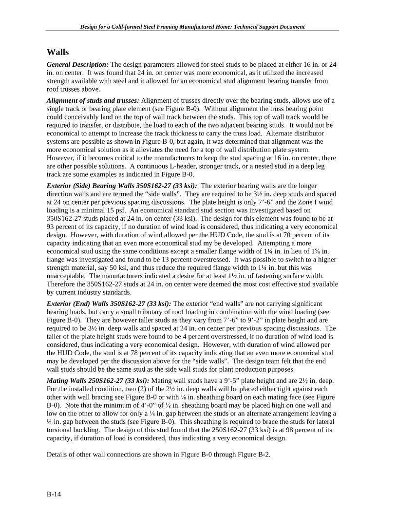
Design for a Cold-formed Steel Framing Manufactured Home: Technical Support Document Walls General Description: The design parameters allowed for steel studs to be placed at either 16 in. or 24 in. on center. It was found that 24 in. on center was more economical, as it utilized the increased strength available with steel and it allowed for an economical stud alignment bearing transfer from roof trusses above. Alignment of studs and trusses: Alignment of trusses directly over the bearing studs, allows use of a single track or bearing plate element (see Figure B-0). Without alignment the truss bearing point could conceivably land on the top of wall track between the studs. This top of wall track would be required to transfer, or distribute, the load to each of the two adjacent bearing studs. It would not be economical to attempt to increase the track thickness to carry the truss load. Alternate distributor systems are possible as shown in Figure B-0, but again, it was determined that alignment was the more economical solution as it alleviates the need for a top of wall distribution plate system. However, if it becomes critical to the manufacturers to keep the stud spacing at 16 in. on center, there are other possible solutions. A continuous L-header, stronger track, or a nested stud in a deep leg track are some examples as indicated in Figure B-0. Exterior (Side) Bearing Walls 350S162-27 (33 ksi): The exterior bearing walls are the longer direction walls and are termed the “side walls”. They are required to be 3½ in. deep studs and spaced at 24 on center per previous spacing discussions. The plate height is only 7’-6” and the Zone I wind loading is a minimal 15 psf. An economical standard stud section was investigated based on 350S162-27 studs placed at 24 in. on center (33 ksi). The design for this element was found to be at 93 percent of its capacity, if no duration of wind load is considered, thus indicating a very economical design. However, with duration of wind allowed per the HUD Code, the stud is at 70 percent of its capacity indicating that an even more economical stud my be developed. Attempting a more economical stud using the same conditions except a smaller flange width of 1¼ in. in lieu of 1⅝ in. flange was investigated and found to be 13 percent overstressed. It was possible to switch to a higher strength material, say 50 ksi, and thus reduce the required flange width to 1¼ in. but this was unacceptable. The manufacturers indicated a desire for at least 1½ in. of fastening surface width. Therefore the 350S162-27 studs at 24 in. on center were deemed the most cost effective stud available by current industry standards. Exterior (End) Walls 350S162-27 (33 ksi): The exterior “end walls” are not carrying significant bearing loads, but carry a small tributary of roof loading in combination with the wind loading (see Figure B-0). They are however taller studs as they vary from 7’-6” to 9’-2” in plate height and are required to be 3½ in. deep walls and spaced at 24 in. on center per previous spacing discussions. The taller of the plate height studs were found to be 4 percent overstressed, if no duration of wind load is considered, thus indicating a very economical design. However, with duration of wind allowed per the HUD Code, the stud is at 78 percent of its capacity indicating that an even more economical stud may be developed per the discussion above for the “side walls”. The design team felt that the end wall studs should be the same stud as the side wall studs for plant production purposes. Mating Walls 250S162-27 (33 ksi): Mating wall studs have a 9’-5” plate height and are 2½ in. deep. For the installed condition, two (2) of the 2½ in. deep walls will be placed either tight against each other with wall bracing see Figure B-0 or with ⅛ in. sheathing board on each mating face (see Figure B-0). Note that the minimum of 4’-0” of ⅛ in. sheathing board may be placed high on one wall and low on the other to allow for only a ⅛ in. gap between the studs or an alternate arrangement leaving a ¼ in. gap between the studs (see Figure B-0). This sheathing is required to brace the studs for lateral torsional buckling. The design of this stud found that the 250S162-27 (33 ksi) is at 98 percent of its capacity, if duration of load is considered, thus indicating a very economical design. Details of other wall connections are shown in Figure B-0 through Figure B-2. B-14
Transcript of Design for a Cold-formed Steel Framing … for a Cold-formed Steel Framing Manufactured Home:...
Design for a Cold-formed Steel Framing Manufactured Home: Technical Support Document
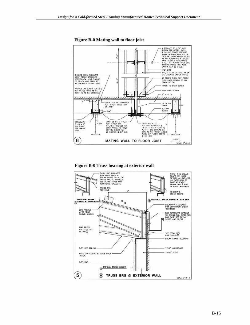
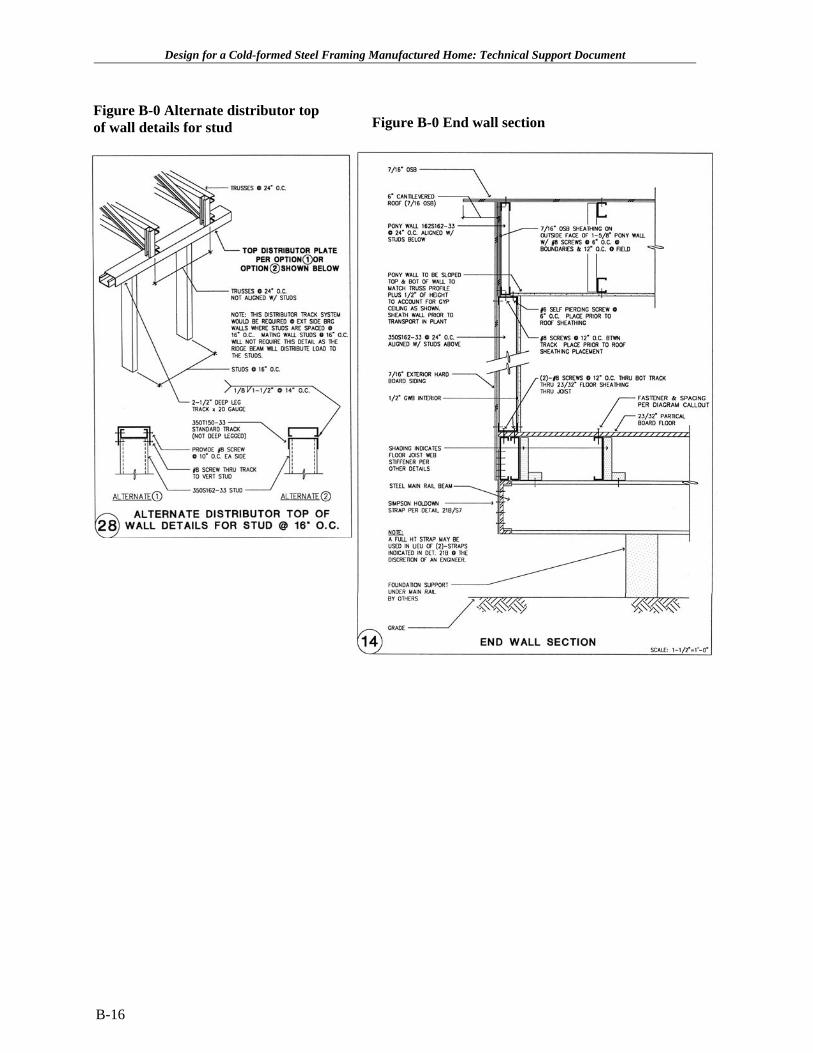
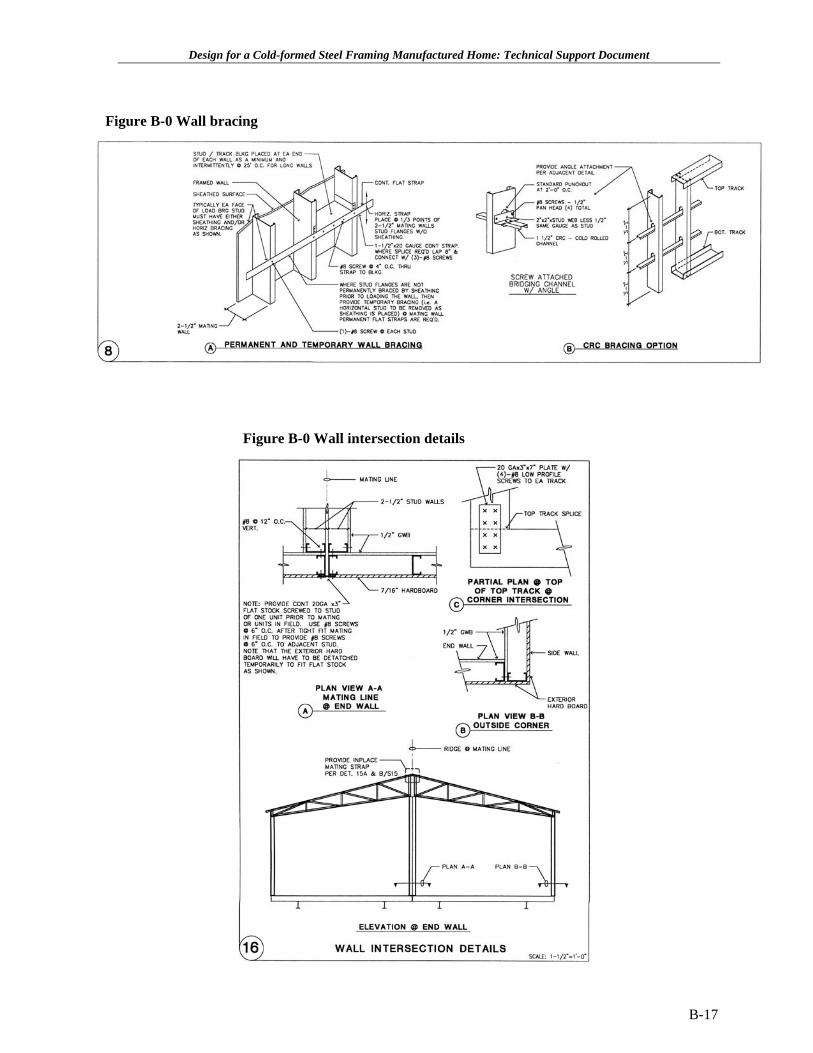
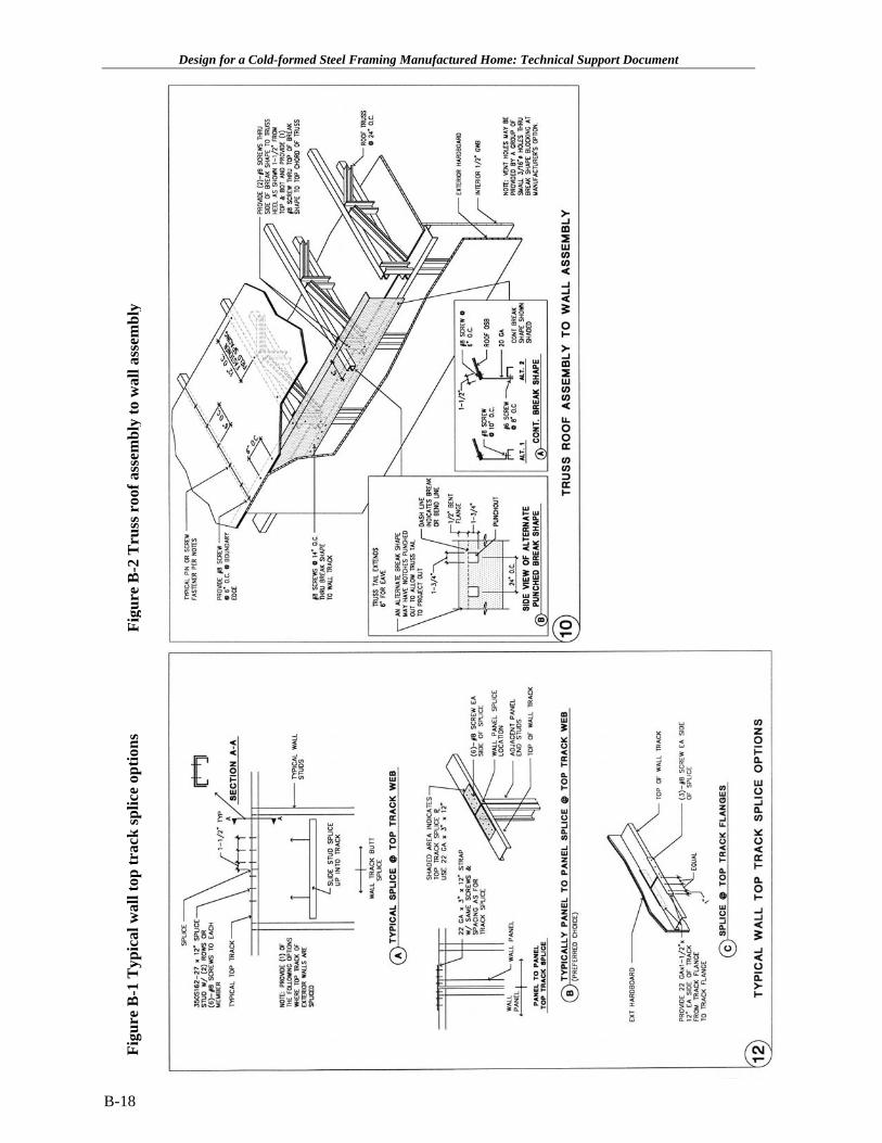
Walls General Description: The design parameters allowed for steel studs to be placed at either 16 in. or 24 in. on center. It was found that 24 in. on center was more economical, as it utilized the increased strength available with steel and it allowed for an economical stud alignment bearing transfer from roof trusses above. Alignment of studs and trusses: Alignment of trusses directly over the bearing studs, allows use of a single track or bearing plate element (see Figure B-0). Without alignment the truss bearing point could conceivably land on the top of wall track between the studs. This top of wall track would be required to transfer, or distribute, the load to each of the two adjacent bearing studs. It would not be economical to attempt to increase the track thickness to carry the truss load. Alternate distributor systems are possible as shown in Figure B-0, but again, it was determined that alignment was the more economical solution as it alleviates the need for a top of wall distribution plate system. However, if it becomes critical to the manufacturers to keep the stud spacing at 16 in. on center, there are other possible solutions. A continuous L-header, stronger track, or a nested stud in a deep leg track are some examples as indicated in Figure B-0. Exterior (Side) Bearing Walls 350S162-27 (33 ksi): The exterior bearing walls are the longer direction walls and are termed the “side walls”. They are required to be 3½ in. deep studs and spaced at 24 on center per previous spacing discussions. The plate height is only 7’-6” and the Zone I wind loading is a minimal 15 psf. An economical standard stud section was investigated based on 350S162-27 studs placed at 24 in. on center (33 ksi). The design for this element was found to be at 93 percent of its capacity, if no duration of wind load is considered, thus indicating a very economical design. However, with duration of wind allowed per the HUD Code, the stud is at 70 percent of its capacity indicating that an even more economical stud my be developed. Attempting a more economical stud using the same conditions except a smaller flange width of 1¼ in. in lieu of 1⅝ in. flange was investigated and found to be 13 percent overstressed. It was possible to switch to a higher strength material, say 50 ksi, and thus reduce the required flange width to 1¼ in. but this was unacceptable. The manufacturers indicated a desire for at least 1½ in. of fastening surface width. Therefore the 350S162-27 studs at 24 in. on center were deemed the most cost effective stud available by current industry standards. Exterior (End) Walls 350S162-27 (33 ksi): The exterior “end walls” are not carrying significant bearing loads, but carry a small tributary of roof loading in combination with the wind loading (see Figure B-0). They are however taller studs as they vary from 7’-6” to 9’-2” in plate height and are required to be 3½ in. deep walls and spaced at 24 in. on center per previous spacing discussions. The taller of the plate height studs were found to be 4 percent overstressed, if no duration of wind load is considered, thus indicating a very economical design. However, with duration of wind allowed per the HUD Code, the stud is at 78 percent of its capacity indicating that an even more economical stud may be developed per the discussion above for the “side walls”. The design team felt that the end wall studs should be the same stud as the side wall studs for plant production purposes. Mating Walls 250S162-27 (33 ksi): Mating wall studs have a 9’-5” plate height and are 2½ in. deep. For the installed condition, two (2) of the 2½ in. deep walls will be placed either tight against each other with wall bracing see Figure B-0 or with ⅛ in. sheathing board on each mating face (see Figure B-0). Note that the minimum of 4’-0” of ⅛ in. sheathing board may be placed high on one wall and low on the other to allow for only a ⅛ in. gap between the studs or an alternate arrangement leaving a ¼ in. gap between the studs (see Figure B-0). This sheathing is required to brace the studs for lateral torsional buckling. The design of this stud found that the 250S162-27 (33 ksi) is at 98 percent of its capacity, if duration of load is considered, thus indicating a very economical design.
Details of other wall connections are shown in Figure B-0 through Figure B-2.
B-14
Design for a Cold-formed Steel Framing Manufactured Home: Technical Support Document
Figure B-0 Mating wall to floor joist
Figure B-0 Truss bearing at exterior wall
B-15
Design for a Cold-formed Steel Framing Manufactured Home: Technical Support Document
Figure B-0 Alternate distributor top Figure B-0 End wall sectionof wall details for stud
B-16
Design for a Cold-formed Steel Framing Manufactured Home: Technical Support Document
Figure B-0 Wall bracing
Figure B-0 Wall intersection details
B-17
Design for a Cold-formed Steel Framing Manufactured Home: Technical Support Document
Figu
re B
-1 T
ypic
al w
all t
op tr
ack
splic
e op
tions
Fi
gure
B-2
Tru
ss r
oof a
ssem
bly
to w
all a
ssem
bly
B-18
Design for a Cold-formed Steel Framing Manufactured Home: Technical Support Document
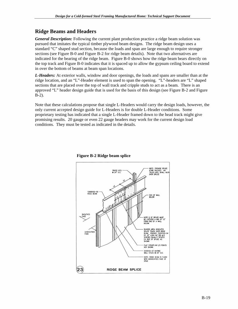
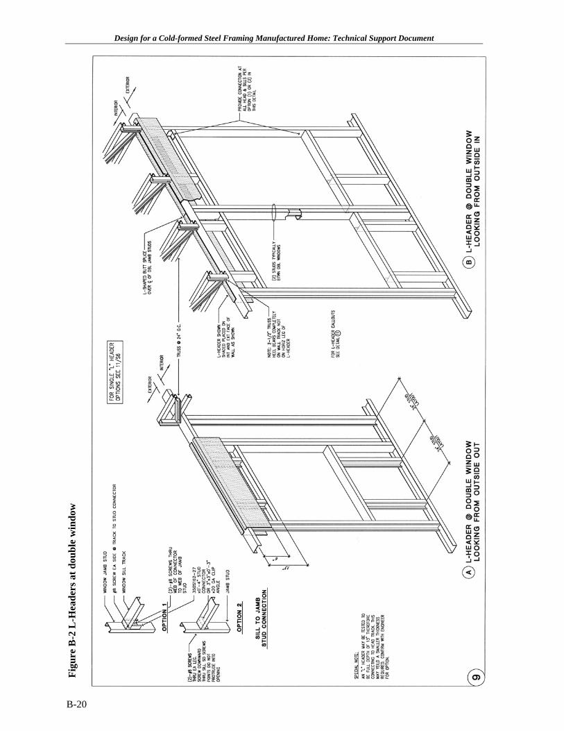
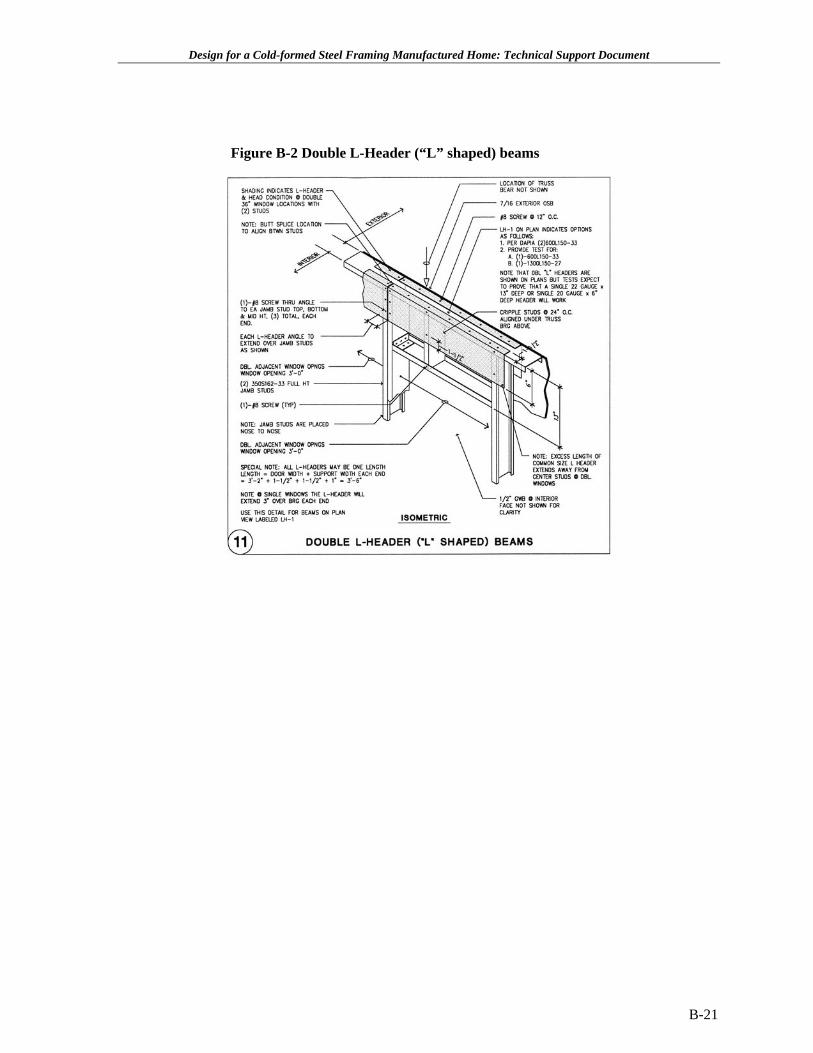
Ridge Beams and Headers General Description: Following the current plant production practice a ridge beam solution was pursued that imitates the typical timber plywood beam designs. The ridge beam design uses a standard “C” shaped stud section, because the loads and span are large enough to require stronger sections (see Figure B-0 and Figure B-2 for ridge beam details). Note that two alternatives are indicated for the bearing of the ridge beam. Figure B-0 shows how the ridge beam bears directly on the top track and Figure B-0 indicates that it is spaced up to allow the gypsum ceiling board to extend in over the bottom of beams at beam span locations. L-Headers: At exterior walls, window and door openings, the loads and spans are smaller than at the ridge location, and an “L”-Header element is used to span the opening. “L”-headers are “L” shaped sections that are placed over the top of wall track and cripple studs to act as a beam. There is an approved “L” header design guide that is used for the basis of this design (see Figure B-2 and Figure B-2).
Note that these calculations propose that single L-Headers would carry the design loads, however, the only current accepted design guide for L-Headers is for double L-Header conditions. Some proprietary testing has indicated that a single L-Header framed down to the head track might give promising results. 20 gauge or even 22 gauge headers may work for the current design load conditions. They must be tested as indicated in the details.
Figure B-2 Ridge beam splice
B-19
Design for a Cold-formed Steel Framing Manufactured Home: Technical Support Document
Figu
re B
-2 L
-Hea
ders
at d
oubl
e w
indo
w
B-20
Design for a Cold-formed Steel Framing Manufactured Home: Technical Support Document
Figure B-2 Double L-Header (“L” shaped) beams
B-21
Design for a Cold-formed Steel Framing Manufactured Home: Technical Support Document
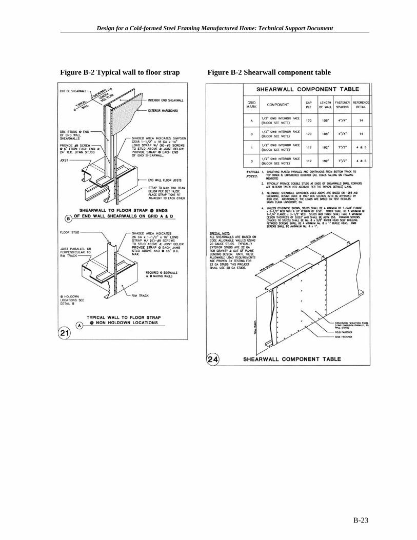
Shearwalls General Description: The lateral system utilizes the current gypsum shearwall tables as found in the UBC 1997 and the IBC 2000. For typical hold downs and shearwall sheathing components (see Figure B-2 and Figure B-2).
The prototype design utilizes economical 350S162-27 studs at 24 in. on center. From a value engineering standpoint, the 27 mil or 22 gauge studs are acceptable. However, 20 gauge studs are required in order to use current shear wall values in the 1997 Uniform Building Code (UBC). This is the only approved code or testing source available for shearwall assemblies utilizing cold-formed studs. The International Building Code (IBC) 2000 has identical information as found in the 1997 edition of the code. If tested, the new shearwall assemblies using 22 gauge studs would be expected to perform to similar load capacities as the current timber shearwall being use by the manufactured home industry. It would also be expected that testing would allow much more cost effective fastener spacing of say 6/12 in. meaning 6 in. at boundaries and 12 in. in the field, instead of the current 4/4 in. and 7/7 in. code assemblies.
These calculations were extrapolated to the given UBC double-sided gypsum wallboard by using one-half of the value for single side gypsum wallboard. A HUD-prescribed factor of safety of 2.5 was used on the UBC ultimate loads in lieu of the 3.0 factor of safety listed in the current 1997 UBC. This follows with the revision found in the new IBC 2000 using a 2.5 factor of safety. The prototype uses ½ in. gypsum wallboard on the interior face of the exterior wall studs for shearwall strength. There are two wall assemblies available with the ½ in. gypsum wallboard, one at 7/7-fastener spacing and one at 4/4-fastener spacing. This design uses the 4/4 on the end walls and the 7/7 on the sidewalls. Minimum lengths of wall required at those capacities are shown on the plans. Simpson CS18 straps for the typical jamb and 48 in. on center strap spacing are used to carry typical hold down loads. The same strap with additional screws is used for the increased hold down requirement at the side shearwalls. These details appear to be cost effective as compared to current timber framed practice.
The prototype design indicates that the typical studs are 22 gauge (27 mil). At locations where shearwalls are indicated on the plan then they must be 20 gauge (33 mil) unless a tested assembly is provided to confirm 22 gauge (27 mil) studs are adequate. Note that the plans indicate all shearwalls are based on code allowable values using 20 gauge studs. Typically, exterior studs are 22 gauge for gravity and out of plane bending design. Until these allowable load requirements are proven by testing for 22 gauge studs, the design will use 20 gauge studs.
B-22
Design for a Cold-formed Steel Framing Manufactured Home: Technical Support Document
Figure B-2 Typical wall to floor strap Figure B-2 Shearwall component table
B-23
Design for a Cold-formed Steel Framing Manufactured Home: Technical Support Document
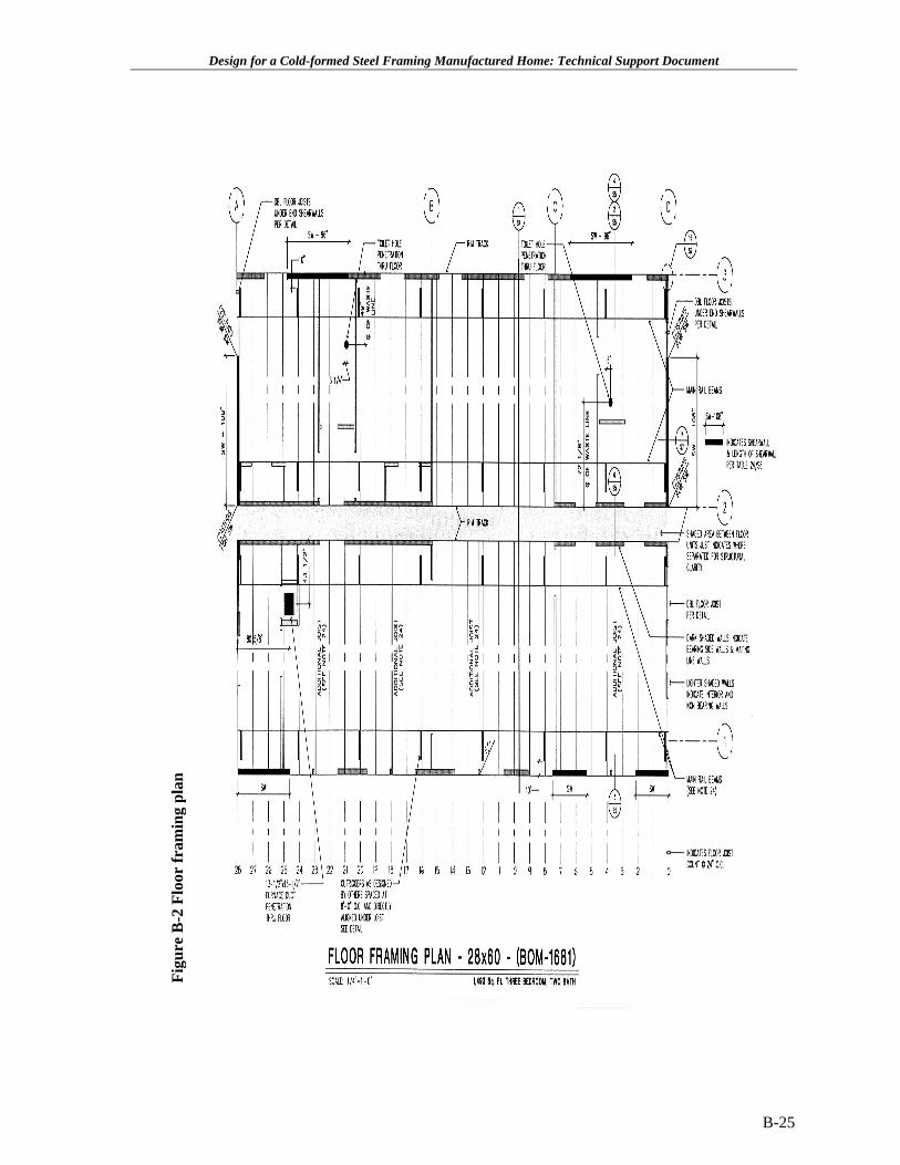
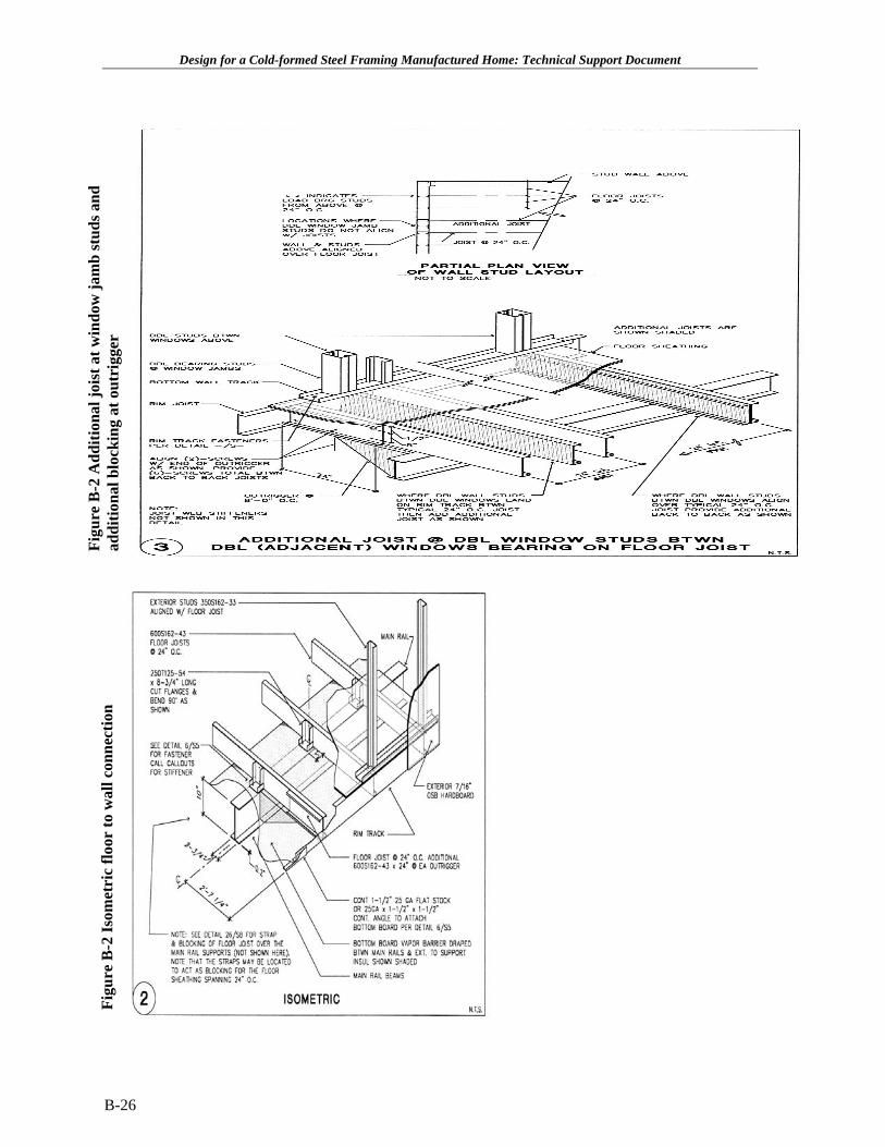
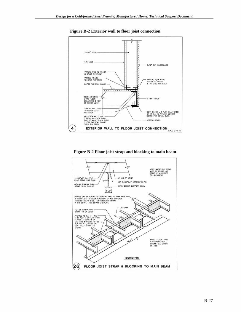
Floor Joist and Chassis Systems General Description: The plans indicated that 600S162-43 joists at 24 in. on center are acceptable given that the chassis frame has outriggers at 8’-0” on center The design investigated using both 8 in. and 6 in. deep floor joists at varying gauges. It was felt that the 6 in. deep 18 gauge joist at 24 in. on center would be most economical. The joist may be punched or un-punched. (See Figure B-0, Figure B-2, Figure B-2, Figure B-2, Figure B-2 and Figure B-2 for typical floor construction details.) Fasteners used to attach the floor sheathing may be screws and or pneumatic pins per details and the framing note #9 from the Framing and Construction Notes. Note that adhesive is used in addition to the fasteners between the floor joist and the sheathing. Note that an additional 24 in. long joist section is required at each joist framing over the outriggers as shown in Figure B-2 and Figure B-2. A two-dimensional joist load sharing analysis approach indicated that the single joists over the outriggers were overstressed in combined bending and shear at the point that they cantilever over the outrigger. However, with the added 24 in. long section of joist to the design was found code acceptable. The floor joist design assumes that a chassis frame assembly will be used that has outriggers spaced at no more than 8’-0” on center. These outrigger elements are a requirement for this prototype. Floor joist blocking is economically detailed to require only 3 blocks within the 56’-0” run of joist (see Figure B-2).
The chassis assembly design is not included as part of the prototype design. The plans indicate that the chassis design (main rail, outrigger, cross bracing, and connections) will be designed by others. Note that at the outrigger locations at 8’-0” on center the aligned floor joist will need to be incorporated into the frame design and shall be design confirmed at that time. It is possible that a heavier gauge joist will be required.
Additional Concluding Design Comments: Economical framing elements: The truss elements have room for further cost reductions through the use of alternate section shapes and material steel strengths. The exterior “side and end” wall studs are for the most part economically designed for their load conditions. However they could be redesigned to use less area of steel by marginally reducing the flange or lip lengths and by increasing the material strengths. This is not possible with current standard shapes available, but is possible by special order. Specialized Roll-forming for Manufactured Housing: Once the manufacturing industry begins using cold-formed materials the cost of producing specialized sections, even proprietary to each production plant is enormous. Plants would eventually have roll-forming capabilities within their own facilities.
B-24
Design for a Cold-formed Steel Framing Manufactured Home: Technical Support Document
Figu
re B
-2 F
loor
fram
ing
plan
B-25
Figu
re B
-2 A
dditi
onal
jois
t at w
indo
w ja
mb
stud
s and
Figu
re B
-2 Is
omet
ric
floor
to w
all c
onne
ctio
n ad
ditio
nal b
lock
ing
at o
utri
gger
B-26
Design for a Cold-formed Steel Framing Manufactured Home: Technical Support Document
Design for a Cold-formed Steel Framing Manufactured Home: Technical Support Document
Figure B-2 Exterior wall to floor joist connection
Figure B-2 Floor joist strap and blocking to main beam
B-27
Design for a Cold-formed Steel Framing Manufactured Home: Technical Support Document
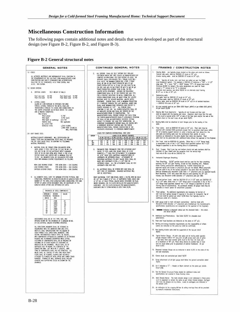
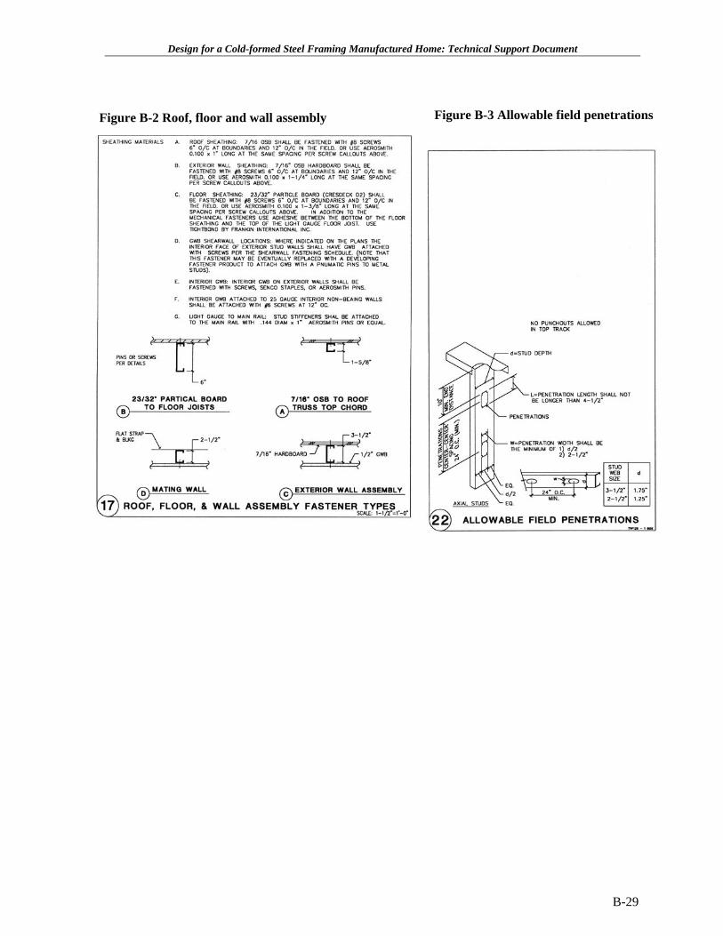
Miscellaneous Construction Information The following pages contain additional notes and details that were developed as part of the structural design (see Figure B-2, Figure B-2, and Figure B-3).
Figure B-2 General structural notes
B-28
Design for a Cold-formed Steel Framing Manufactured Home: Technical Support Document
Figure B-2 Roof, floor and wall assembly Figure B-3 Allowable field penetrations
B-29