Residential Hip Roof Framing Using Cold-Formed Steel Members
63
research report Residential Hip Roof Framing Using Cold-Formed Steel Members RESEARCH REPORT RP06-2 2006 American Iron and Steel Institute
Transcript of Residential Hip Roof Framing Using Cold-Formed Steel Members
rese
arch
repo
rt
Residential Hip Roof Framing Using Cold-Formed Steel Members
R E S E A R C H R E P O R T R P 0 6 - 2 2 0 0 6
American Iron and Steel Institute
Residential Hip Roof Framing Using Cold-Formed Steel Members i
DISCLAIMER
The material contained herein has been developed by researchers based on their research findings and is for general information only. The information in it should not be used without first securing competent advice with respect to its suitability for any given application. The publication of the information is not intended as a representation or warranty on the part of the American Iron and Steel Institute, Steel Framing Alliance, or of any other person named herein, that the information is suitable for any general or particular use or of freedom from infringement of any patent or patents. Anyone making use of the information assumes all liability arising from such use.
Copyright 2006 American Iron and Steel Institute / Steel Framing Alliance
ii Residential Hip Roof Framing Using Cold-Formed Steel Members
PREFACE
The objectives of this project were to investigate a more rational rafter design methodology for both gable and hip roofs and develop all the necessary tables, details and specification requirements for hip roof framing members and connections for addition to the AISI Standard for Cold-Formed Steel framing – Prescriptive Method for One and Two Family Dwellings [Prescriptive Method]. This report accomplishes these objectives, provides useful insight and suggests future study topics that should assist in identifying and prioritizing future research needs.
It is expected that portions of this report will indeed be incorporated in the Prescriptive Method. As such, the results of this work will have a lasting and beneficial impact on the steel-framed residential construction industry.
Research Team Steel Framing Alliance
i
Civil Engineering Study 06-1 Cold-Formed Steel Series
Final Report
RESIDENTIAL HIP ROOF FRAMING USING COLD-FORMED STEEL MEMBERS
by
Luke Waldo Research Assistant
Sutton F. Stephens Roger A. LaBoube Project Directors
A Research Project Sponsored by the American Iron and Steel Institute
July, 2006
Department of Civil Engineering Wei-Wen Yu Center for Cold-Formed Steel Structures
University of Missouri-Rolla Rolla, Missouri
2
TABLE OF CONTENTS
Page
PREFACE 4
1.0 Analysis of Hip Roof System 6
1.1 Analysis Procedure 6
1.1.1 Model Development 6
1.1.2 Results of RISA-3D Analysis 10
1.2 Comparison of Unsheathed and Sheathed Roof Framing Systems 12
1.2.1 Analysis Summary and Comparison 12
1.3 Conclusions 12
1.4 Recommendations for Further Research 13
2.0 Hip Framing Analysis and Design 26
2.1 General 26
2.2 Loads 26
2.2.1 Dead Loads (D) 27
2.2.2 Roof Live Load (Lr) 27
2.2.3 Roof Snow Load (S) 27
2.2.4 Wind Load (W) 27
2.3 Load Combinations 28
2.4 Hip Member Analysis and Design 29
2.5 Hip Member Support Column 29
2.5.1 Column Above Ceiling 30
2.5.2 Column Support Below Ceiling 31
3
2.6 Connections 31
2.6.1 Hip Member Connection at Ridge 32
2.6.2 Hip Member Connection at Wall Corner 33
2.6.3 Hip Support Column Connection at the Ceiling 33
2.7 Alternate Hip and Ridge Member Configuration 34
2.8 Conclusions 35
APPENDIX A – DESIGN CALCULATIONS 44
4
PREFACE
Cold-formed steel is continuing to increase in popularity in the residential construction
market and is gaining an increasing market share compared with other construction materials.
Conventionally framed roof construction uses rafters, ridge members, and ceiling joists and does not
include any supplemental interior ridge member supports or collar ties between rafters although
ceiling joists may be supported by an interior bearing wall. At hip ends, conventionally framed
construction uses hip members and jack rafters, and ridge member support braces are also
commonly used. Section R802.3 of the International Residential Code (ICC 2003) states “Hip and
valley rafters shall be supported at the ridge by a brace to a bearing partition or be designed to carry
and distribute the specific load at that point.” Conventional framing has traditionally been used in
light framed wood structures and more recently in roofs framed with cold-formed steel members.
The American Iron and Steel Institute developed the Standard for Cold-Formed Steel
Framing – Prescriptive Method for One and Two Family Dwellings (AISI 2002). This Standard is
useful for the design of residential projects because it allows standard one and two story residential
structures to be designed without the services of an architect or structural engineer. The current
edition of the Prescriptive Method, however, does not address the design of the members necessary
to construct hip roofs. Accordingly, the AISI Committee on Framing Standards (COFS) determined
that research should be carried out to develop all the information necessary to allow for the
construction of hip roofs using the Prescriptive Method. One of the objectives of this study was to
investigate a more rational rafter design methodology for both gable and hip roofs. A second
objective was to develop all the necessary tables, details and specification requirements for
additions to the Prescriptive Method, and the Commentary to the Prescriptive Method for hip roof
framing members and connections.
5
This report is based mainly on a thesis submitted to the Faculty of the Graduate School of
the Kansas State University in partial fulfillment of the requirements for the degree of Masters of
Science in Architectural Engineering.
Technical guidance for this study was provided by the Steel Framing Alliance’s Project
Monitoring Task Group (Bill Babich, Nader Elhajj, Steve Fox, Dick Layding, and Steve Walker),
and the American Iron and Steel Institute’s Prescriptive Method Subcommittee (Steve Fox,
Chairperson). The Project Monitoring Task Group and the Subcommittee’s guidance is gratefully
acknowledged. Appreciation is also extended to Jay Larson, AISI for his guidance and assistance.
Partial funding for this study was provided by the American Iron and Steel Institutes. The authors
extend their appreciation to AISI for the financial support.
6
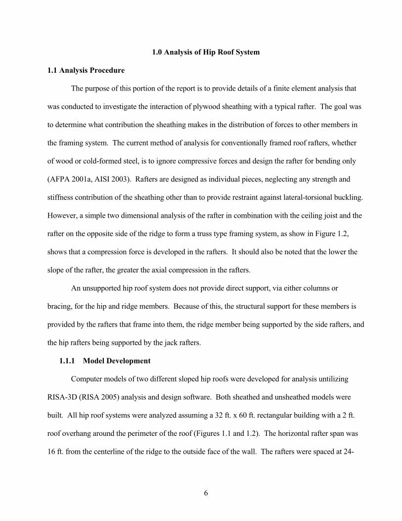
1.0 Analysis of Hip Roof System
1.1 Analysis Procedure
The purpose of this portion of the report is to provide details of a finite element analysis that
was conducted to investigate the interaction of plywood sheathing with a typical rafter. The goal was
to determine what contribution the sheathing makes in the distribution of forces to other members in
the framing system. The current method of analysis for conventionally framed roof rafters, whether
of wood or cold-formed steel, is to ignore compressive forces and design the rafter for bending only
(AFPA 2001a, AISI 2003). Rafters are designed as individual pieces, neglecting any strength and
stiffness contribution of the sheathing other than to provide restraint against lateral-torsional buckling.
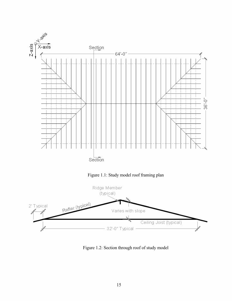
However, a simple two dimensional analysis of the rafter in combination with the ceiling joist and the
rafter on the opposite side of the ridge to form a truss type framing system, as show in Figure 1.2,
shows that a compression force is developed in the rafters. It should also be noted that the lower the
slope of the rafter, the greater the axial compression in the rafters.
An unsupported hip roof system does not provide direct support, via either columns or
bracing, for the hip and ridge members. Because of this, the structural support for these members is
provided by the rafters that frame into them, the ridge member being supported by the side rafters, and
the hip rafters being supported by the jack rafters.
1.1.1 Model Development
Computer models of two different sloped hip roofs were developed for analysis untilizing
RISA-3D (RISA 2005) analysis and design software. Both sheathed and unsheathed models were
built. All hip roof systems were analyzed assuming a 32 ft. x 60 ft. rectangular building with a 2 ft.
roof overhang around the perimeter of the roof (Figures 1.1 and 1.2). The horizontal rafter span was
16 ft. from the centerline of the ridge to the outside face of the wall. The rafters were spaced at 24-
7
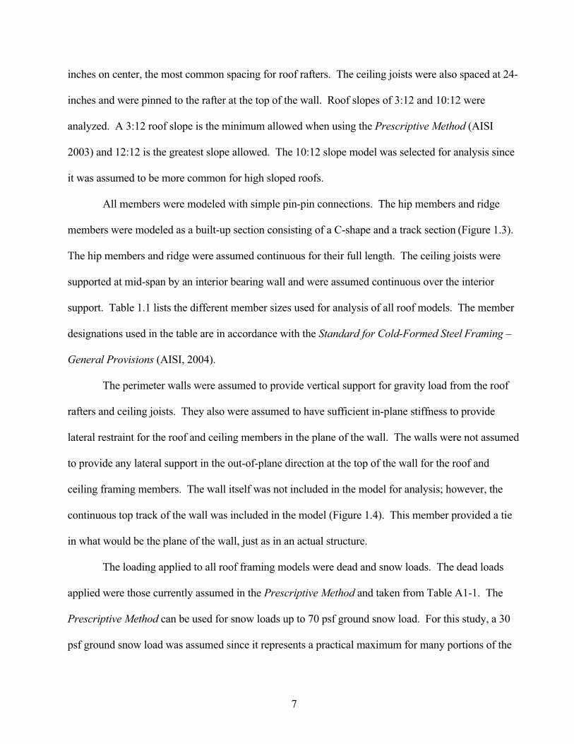
inches on center, the most common spacing for roof rafters. The ceiling joists were also spaced at 24-
inches and were pinned to the rafter at the top of the wall. Roof slopes of 3:12 and 10:12 were
analyzed. A 3:12 roof slope is the minimum allowed when using the Prescriptive Method (AISI
2003) and 12:12 is the greatest slope allowed. The 10:12 slope model was selected for analysis since
it was assumed to be more common for high sloped roofs.
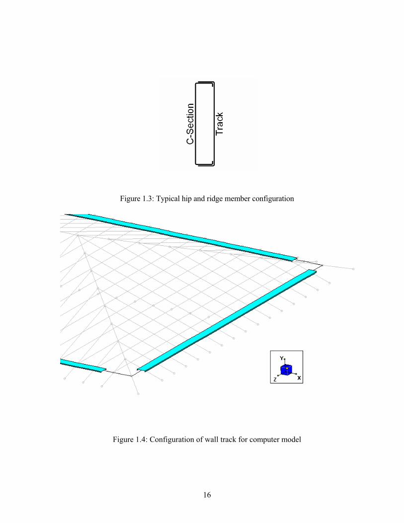
All members were modeled with simple pin-pin connections. The hip members and ridge
members were modeled as a built-up section consisting of a C-shape and a track section (Figure 1.3).
The hip members and ridge were assumed continuous for their full length. The ceiling joists were
supported at mid-span by an interior bearing wall and were assumed continuous over the interior
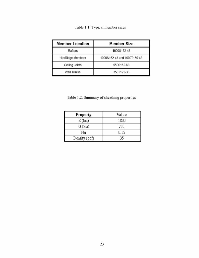
support. Table 1.1 lists the different member sizes used for analysis of all roof models. The member
designations used in the table are in accordance with the Standard for Cold-Formed Steel Framing –
General Provisions (AISI, 2004).
The perimeter walls were assumed to provide vertical support for gravity load from the roof
rafters and ceiling joists. They also were assumed to have sufficient in-plane stiffness to provide
lateral restraint for the roof and ceiling members in the plane of the wall. The walls were not assumed
to provide any lateral support in the out-of-plane direction at the top of the wall for the roof and
ceiling framing members. The wall itself was not included in the model for analysis; however, the
continuous top track of the wall was included in the model (Figure 1.4). This member provided a tie
in what would be the plane of the wall, just as in an actual structure.
The loading applied to all roof framing models were dead and snow loads. The dead loads
applied were those currently assumed in the Prescriptive Method and taken from Table A1-1. The
Prescriptive Method can be used for snow loads up to 70 psf ground snow load. For this study, a 30
psf ground snow load was assumed since it represents a practical maximum for many portions of the
8
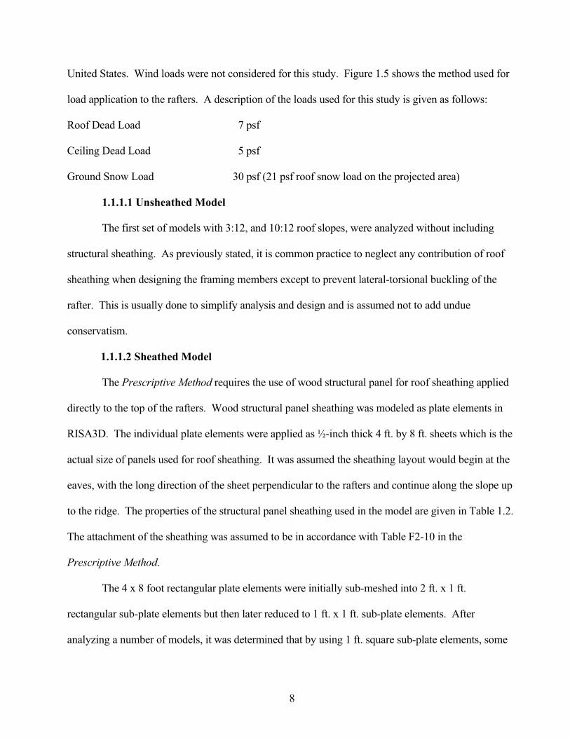
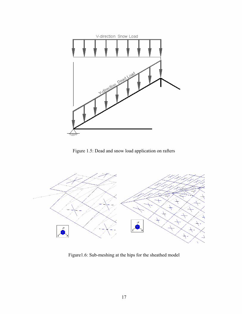
United States. Wind loads were not considered for this study. Figure 1.5 shows the method used for
load application to the rafters. A description of the loads used for this study is given as follows:
Roof Dead Load 7 psf
Ceiling Dead Load 5 psf
Ground Snow Load 30 psf (21 psf roof snow load on the projected area)
1.1.1.1 Unsheathed Model
The first set of models with 3:12, and 10:12 roof slopes, were analyzed without including
structural sheathing. As previously stated, it is common practice to neglect any contribution of roof
sheathing when designing the framing members except to prevent lateral-torsional buckling of the
rafter. This is usually done to simplify analysis and design and is assumed not to add undue
conservatism.
1.1.1.2 Sheathed Model
The Prescriptive Method requires the use of wood structural panel for roof sheathing applied
directly to the top of the rafters. Wood structural panel sheathing was modeled as plate elements in
RISA3D. The individual plate elements were applied as ½-inch thick 4 ft. by 8 ft. sheets which is the
actual size of panels used for roof sheathing. It was assumed the sheathing layout would begin at the
eaves, with the long direction of the sheet perpendicular to the rafters and continue along the slope up
to the ridge. The properties of the structural panel sheathing used in the model are given in Table 1.2.
The attachment of the sheathing was assumed to be in accordance with Table F2-10 in the
Prescriptive Method.
The 4 x 8 foot rectangular plate elements were initially sub-meshed into 2 ft. x 1 ft.
rectangular sub-plate elements but then later reduced to 1 ft. x 1 ft. sub-plate elements. After
analyzing a number of models, it was determined that by using 1 ft. square sub-plate elements, some
9
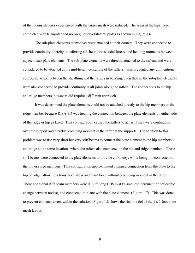
of the inconsistencies experienced with the larger mesh were reduced. The areas at the hips were
completed with triangular and non-regular quadrilateral plates as shown in Figure 1.6.
The sub-plate elements themselves were attached at their corners. They were connected to
provide continuity, thereby transferring all shear forces, axial forces, and bending moments between
adjacent sub-plate elements. The sub-plate elements were directly attached to the rafters, and were
considered to be attached at the mid-height centerline of the rafters. This prevented any unintentional
composite action between the sheathing and the rafters in bending, even though the sub-plate elements
were also connected to provide continuity at all joints along the rafters. The connections to the hip
and ridge members, however, did require a different approach.
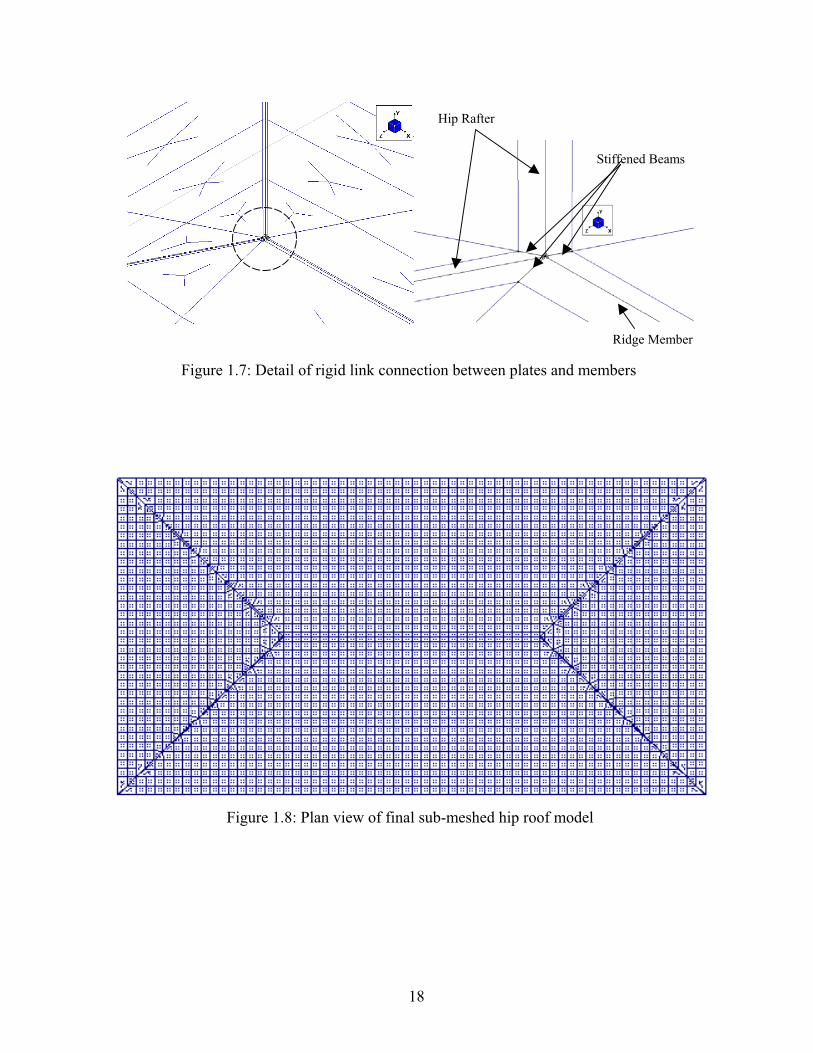
It was determined the plate elements could not be attached directly to the hip members or the
ridge member because RISA-3D was treating the connection between the plate elements on either side
of the ridge or hip as fixed. This configuration caused the rafters to act as if they were continuous
over the support and thereby producing moment in the rafter at the supports. The solution to this
problem was to use very short but very stiff beams to connect the plate element to the hip members
and ridge at the same locations where the rafters also connected to the hip and ridge members. These
stiff beams were connected to the plate elements to provide continuity, while being pin connected to
the hip or ridge members. This configuration approximated a pinned connection from the plate to the
hip or ridge, allowing a transfer of shear and axial force without producing moment in the rafter.
These additional stiff beam members were 0.02 ft. long (RISA-3D’s smallest increment of noticeable
change between nodes), and connected in-plane with the plate elements (Figure 1.7). This was done
to prevent coplanar errors within the solution. Figure 1.8 shows the final model of the 1 x 1 foot plate
mesh layout.
10
1.1.2 Results of RISA-3D Analysis
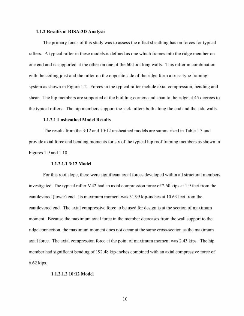
The primary focus of this study was to assess the effect sheathing has on forces for typical
rafters. A typical rafter in these models is defined as one which frames into the ridge member on
one end and is supported at the other on one of the 60-foot long walls. This rafter in combination
with the ceiling joist and the rafter on the opposite side of the ridge form a truss type framing
system as shown in Figure 1.2. Forces in the typical rafter include axial compression, bending and
shear. The hip members are supported at the building corners and span to the ridge at 45 degrees to
the typical rafters. The hip members support the jack rafters both along the end and the side walls.
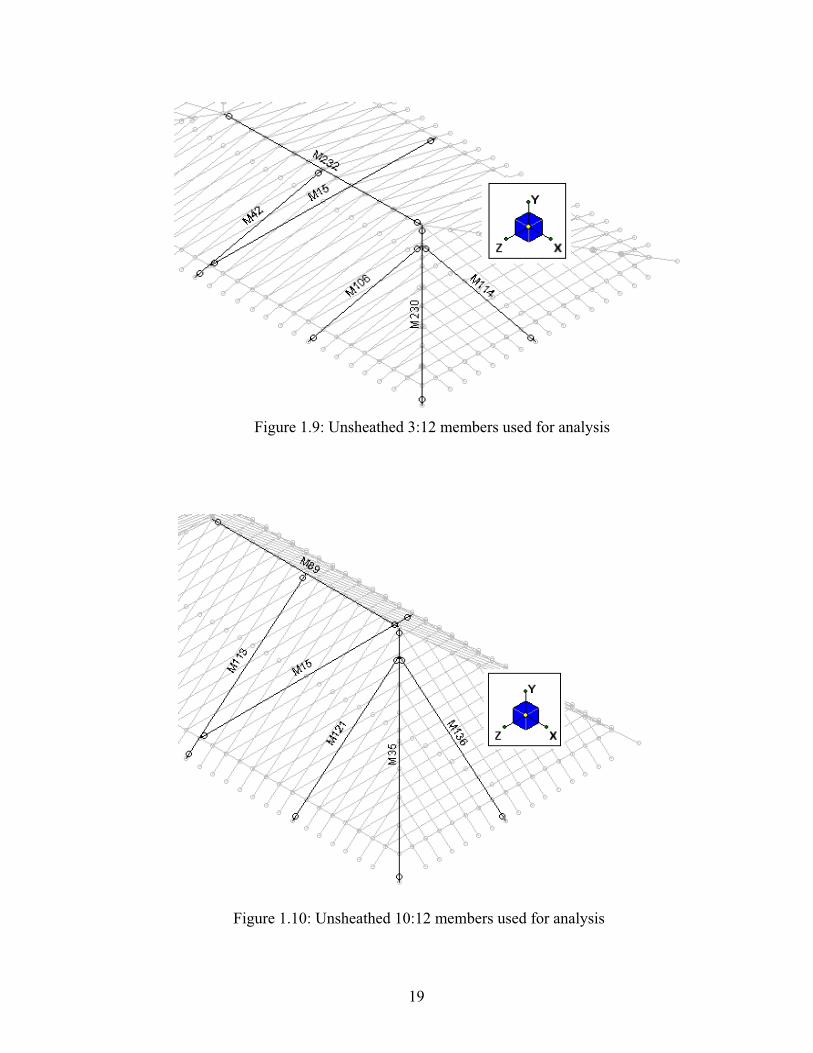
1.1.2.1 Unsheathed Model Results
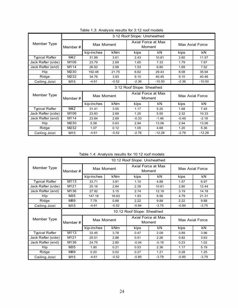
The results from the 3:12 and 10:12 unsheathed models are summarized in Table 1.3 and
provide axial force and bending moments for six of the typical hip roof framing members as shown in
Figures 1.9.and 1.10.
1.1.2.1.1 3:12 Model
For this roof slope, there were significant axial forces developed within all structural members
investigated. The typical rafter M42 had an axial compression force of 2.60 kips at 1.9 feet from the
cantilevered (lower) end. Its maximum moment was 31.99 kip-inches at 10.63 feet from the
cantilevered end. The axial compressive force to be used for design is at the section of maximum
moment. Because the maximum axial force in the member decreases from the wall support to the
ridge connection, the maximum moment does not occur at the same cross-section as the maximum
axial force. The axial compression force at the point of maximum moment was 2.43 kips. The hip
member had significant bending of 192.48 kip-inches combined with an axial compressive force of
6.62 kips.
1.1.2.1.2 10:12 Model
11
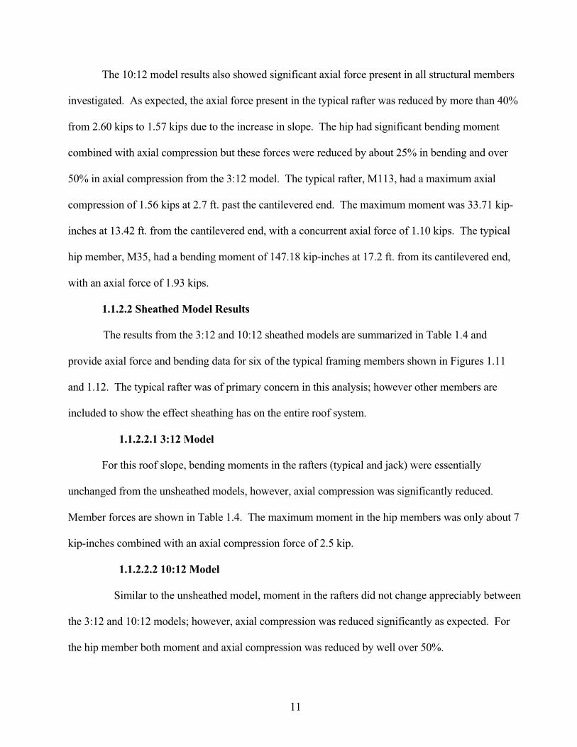
The 10:12 model results also showed significant axial force present in all structural members
investigated. As expected, the axial force present in the typical rafter was reduced by more than 40%
from 2.60 kips to 1.57 kips due to the increase in slope. The hip had significant bending moment
combined with axial compression but these forces were reduced by about 25% in bending and over
50% in axial compression from the 3:12 model. The typical rafter, M113, had a maximum axial
compression of 1.56 kips at 2.7 ft. past the cantilevered end. The maximum moment was 33.71 kip-
inches at 13.42 ft. from the cantilevered end, with a concurrent axial force of 1.10 kips. The typical
hip member, M35, had a bending moment of 147.18 kip-inches at 17.2 ft. from its cantilevered end,
with an axial force of 1.93 kips.
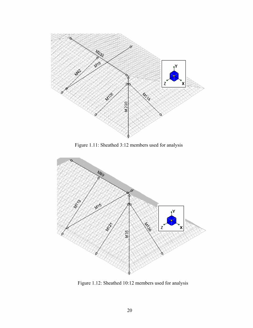
1.1.2.2 Sheathed Model Results
The results from the 3:12 and 10:12 sheathed models are summarized in Table 1.4 and
provide axial force and bending data for six of the typical framing members shown in Figures 1.11
and 1.12. The typical rafter was of primary concern in this analysis; however other members are
included to show the effect sheathing has on the entire roof system.
1.1.2.2.1 3:12 Model
For this roof slope, bending moments in the rafters (typical and jack) were essentially
unchanged from the unsheathed models, however, axial compression was significantly reduced.
Member forces are shown in Table 1.4. The maximum moment in the hip members was only about 7
kip-inches combined with an axial compression force of 2.5 kip.
1.1.2.2.2 10:12 Model
Similar to the unsheathed model, moment in the rafters did not change appreciably between
the 3:12 and 10:12 models; however, axial compression was reduced significantly as expected. For
the hip member both moment and axial compression was reduced by well over 50%.
12
1.2 Comparison of Unsheathed and Sheathed Roof Framing Systems
1.2.1 Analysis Summary and Comparison
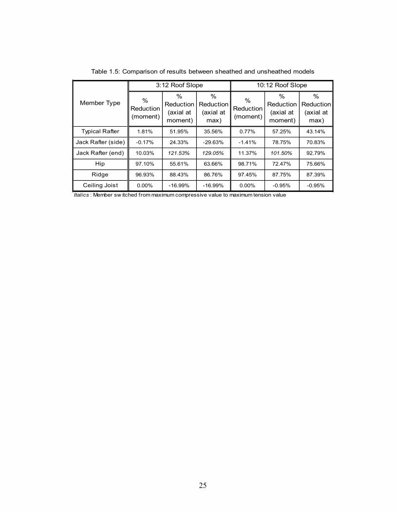
Table 1.5 summarizes the results between the sheathed and unsheathed models. The results
indicate the inclusion of sheathing greatly reduces the axial compression in the typical rafters.
Including the sheathing in the analysis also significantly reduces bending moment in the hip and
ridge members, while also reducing the axial compression.
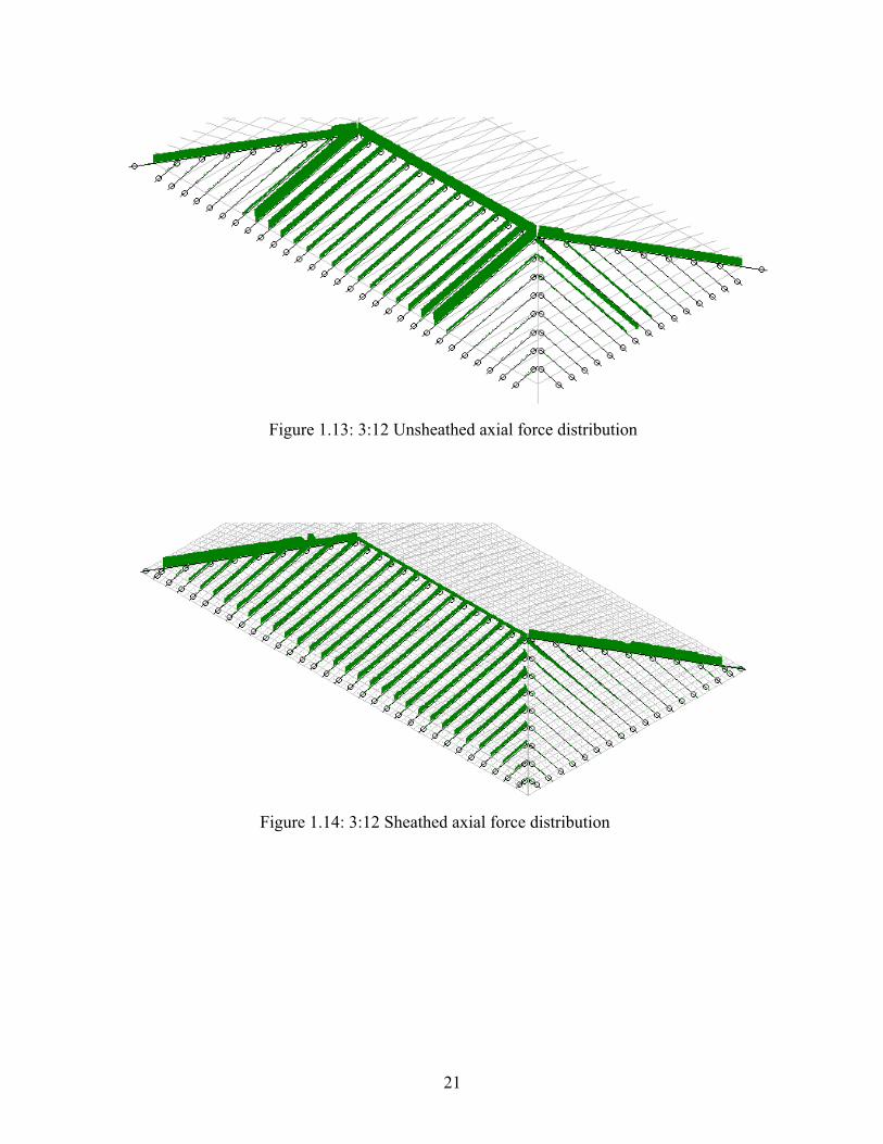
Comparison of the unsheathed and sheathed roof systems shows that the roof system acts
more as a stiffened shell, rather than as individual members acting independently. Rafters and the
hip members share the axial forces with the sheathing. In general, the sheathing acts to distribute
axial forces more evenly between the rafters and hip members. Both roof slopes showed over 50%
reduction in axial compression in the side rafters at the point of maximum bending due to the
contribution of the structural sheathing. There was also a 35-40% reduction in the maximum axial
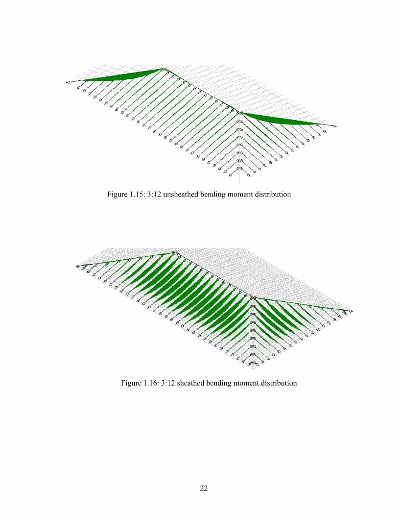
compression in the side rafters. Figures 1.13 through 1.16 are provided as a graphical
representation of the relative axial force and moment distributions for the 3:12 slope model for both
the unsheathed and sheathed conditions. There is no correlation of relative magnitude between
figures, only between members of each figure.
1.3 Conclusions
It is apparent from the results of this preliminary study there is an interaction between the
wood structural panel sheathing and the cold-formed steel framing members of the hip roof system.
Through the inclusion of sheathing in the analysis of the roof framing system, axial forces are
distributed between the sheathing, rafters and hip members. The result is a lower axial force present
in the rafters and lower axial and bending forces in the hip members. The main advantage for
considering sheathing to act together with the framing members is that the rafters and hip members
13
can be designed as much smaller members, thereby reducing the cost of construction. Current
design methodologies for both wood and cold-formed steel roofs framed with rafters do not
consider any contribution of the roof sheathing. These roofs are shown to be typically
unconservative when a rational analysis approach is used. Since current design methodologies are
simplified and unconservative, it is apparent that in reality, the sheathing is acting with the framing
members to provide the additional margin of safety and prevent a wide spread failures of this type
of roof framing system.
1.4 Recommendations for Further Research
Based on the conclusions drawn from the results of this study, it is apparent the sheathing in
conventionally framed roof systems works in conjunction with the rafters as a structural system to
resist applied loads. The results indicate that the sheathing has the effect of reducing axial forces in
rafters and hip members. Further investigation is required to fully quantify the contribution and of
the sheathing and derive a design methodology that accurately models the system behavior and can
be easily used for design. Items for further research should include:
Additional analysis for models with different roof slopes, building widths and load
combinations. This is needed to develop a clearer understanding of force distribution
and the effect of different slopes, spans and loads on force distribution.
Develop models for gable roofs to determine if the sheathing provides the same
advantage as it appears to for hip roofs.
Determine connection requirements between the wood structural panel sheathing and the
cold-formed steel rafters.
Determine minimum wood structural panel sheathing material properties required.
14
Develop the design methodology that correctly predicts the behavior of the sheathing
and the cold-formed steel members for the hip roof framing system. The design
methodology should cover design of the sheathing, rafters, hip members, ridge member
and connections between the sheathing and supporting members.
15
Figure 1.1: Study model roof framing plan
Figure 1.2: Section through roof of study model
16
Figure 1.3: Typical hip and ridge member configuration
Figure 1.4: Configuration of wall track for computer model
17
Figure 1.5: Dead and snow load application on rafters
Figure1.6: Sub-meshing at the hips for the sheathed model
18
Hip Rafter
Ridge Member
Stiffened Beams
Figure 1.7: Detail of rigid link connection between plates and members
Figure 1.8: Plan view of final sub-meshed hip roof model
19
Figure 1.9: Unsheathed 3:12 members used for analysis
Figure 1.10: Unsheathed 10:12 members used for analysis
20
Figure 1.11: Sheathed 3:12 members used for analysis
Figure 1.12: Sheathed 10:12 members used for analysis
21
Figure 1.14: 3:12 Sheathed axial force distribution
Figure 1.13: 3:12 Unsheathed axial force distribution
22
Figure 1.16: 3:12 sheathed bending moment distribution
Figure 1.15: 3:12 unsheathed bending moment distribution
23
Table 1.2: Summary of sheathing properties
Table 1.1: Typical member sizes
24
kip-inches kNm kips kN kips kN
Typical Rafter M42 31.99 3.61 2.43 10.81 2.60 11.57
Jack Rafter (side) M106 23.79 2.69 1.65 7.33 1.79 7.97
Jack Rafter (end) M114 26.50 2.99 1.53 6.80 1.69 7.52
Hip M230 192.48 21.75 6.62 29.43 8.08 35.94
Ridge M232 34.76 3.93 9.10 40.45 9.10 40.46
Ceiling Joist M15 -4.61 -0.52 -2.36 -10.50 -2.36 -10.50
kip-inches kNm kips kN kips kN
Typical Rafter M42 31.41 3.55 1.17 5.20 1.68 7.45
Jack Rafter (side) M106 23.83 2.69 1.25 5.55 2.32 10.33
Jack Rafter (end) M114 23.84 2.69 -0.33 -1.46 -0.49 -2.18
Hip M230 5.58 0.63 2.94 13.06 2.94 13.06
Ridge M232 1.07 0.12 1.05 4.68 1.20 5.36
Ceiling Joist M15 -4.61 -0.52 -2.76 -12.28 -2.76 -12.28
Member Type
3:12 Roof Slope: Sheathed
Member #Max Moment
Axial Force at Max
MomentMax Axial Force
Member Type
3:12 Roof Slope: Unsheathed
Member #Max Moment
Axial Force at Max
MomentMax Axial Force
Table 1.3: Analysis results for 3:12 roof models
kip-inches kNm kips kN kips kN
Typical Rafter M113 33.71 3.81 1.10 4.88 1.57 6.97
Jack Rafter (side) M121 25.16 2.84 2.39 10.61 2.80 12.44
Jack Rafter (end) M136 27.92 3.15 2.74 12.18 3.19 14.18
Hip M35 147.18 16.63 1.93 8.56 4.79 21.31
Ridge M89 7.79 0.88 2.22 9.88 2.22 9.88
Ceiling Joist M15 -4.61 -0.52 -0.84 -3.75 -0.84 -3.75
kip-inches kNm kips kN kips kN
Typical Rafter M113 33.45 3.78 0.47 2.09 0.89 3.96
Jack Rafter (side) M121 25.51 2.88 0.51 2.26 0.82 3.63
Jack Rafter (end) M136 24.75 2.80 -0.04 -0.18 0.23 1.02
Hip M35 1.90 0.21 0.53 2.36 1.17 5.19
Ridge M89 0.20 0.02 0.27 1.21 0.28 1.25
Ceiling Joist M15 -4.61 -0.52 -0.85 -3.79 -0.85 -3.79
Member #Max Moment
Axial Force at Max
MomentMax Axial Force
Member TypeMember #
Table 1.4: Analysis results for 10:12 roof models
Max Moment
10:12 Roof Slope: Unsheathed
Axial Force at Max
MomentMax Axial Force
Member Type
10:12 Roof Slope: Sheathed
25
%
Reduction
(moment)
%
Reduction
(axial at
moment)
%
Reduction
(axial at
max)
%
Reduction
(moment)
%
Reduction
(axial at
moment)
%
Reduction
(axial at
max)
Typical Rafter 1.81% 51.95% 35.56% 0.77% 57.25% 43.14%
Jack Rafter (side) -0.17% 24.33% -29.63% -1.41% 78.75% 70.83%
Jack Rafter (end) 10.03% 121.53% 129.05% 11.37% 101.50% 92.79%
Hip 97.10% 55.61% 63.66% 98.71% 72.47% 75.66%
Ridge 96.93% 88.43% 86.76% 97.45% 87.75% 87.39%
Ceiling Joist 0.00% -16.99% -16.99% 0.00% -0.95% -0.95%
Italics : Member sw itched from maximum compressive value to maximum tension value
Member Type
Table 1.5: Comparison of results between sheathed and unsheathed models
10:12 Roof Slope3:12 Roof Slope
26
2.0 Hip Framing Analysis and Design
2.1 General
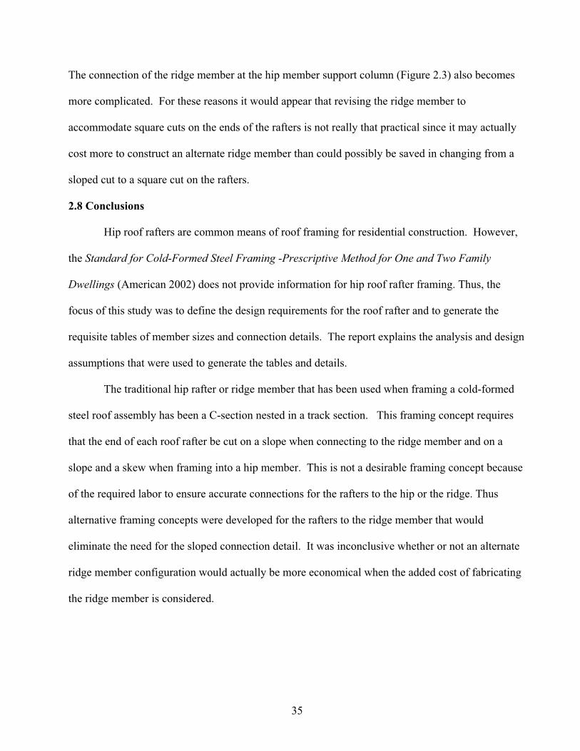
Hip members provide support for jack rafters and span from the building corners to the
ridge. They are orientated at 45-degrees to the building walls as shown in Figure 2.1. The hip
members are assumed to be single span members with pinned ends. Based on the findings
described in Section 1, the hip member for an unsupported hip roof framing system will have
considerable bending moment combined with a very significant axial compressive force.
Additionally, the rafters that frame into the ridge member closest to the hip member to ridge
connection also have a much higher axial load and bending moment than other rafters located
further away from this point. The design of hip members and rafters for these high combined forces
makes it uneconomical to construct these members out of cold-formed steel for unsupported hip
roof framing systems. To essentially eliminate the axial force in the hip member and the excessive
axial compressive force in the rafter, a column to support the upper end of the hip members was
introduced at the point where the hip members and ridge meet. All rafters can then be treated as a
typical rafter design as detailed in the Prescriptive Method (AISI 2002). The hip member is
considered a simply supported, single span beam supported at the lower end by the building corner
and by the column at the upper end designed primarily for bending and deflection. Tables were
developed and are provided for hip members, supporting columns and connections.
2.2 Loads
Loads used for the analysis and design of the hip framing are roof dead load (D), roof live
load (Lr), snow load (S) and wind load (W). ASCE7-05 (ASCE 2005) was used to determine the
MWFRS wind load on the hip members, columns and their corresponding connections. LRFD load
combinations were used from ASCE7-05 to identify the critical design moments for bending, axial
27
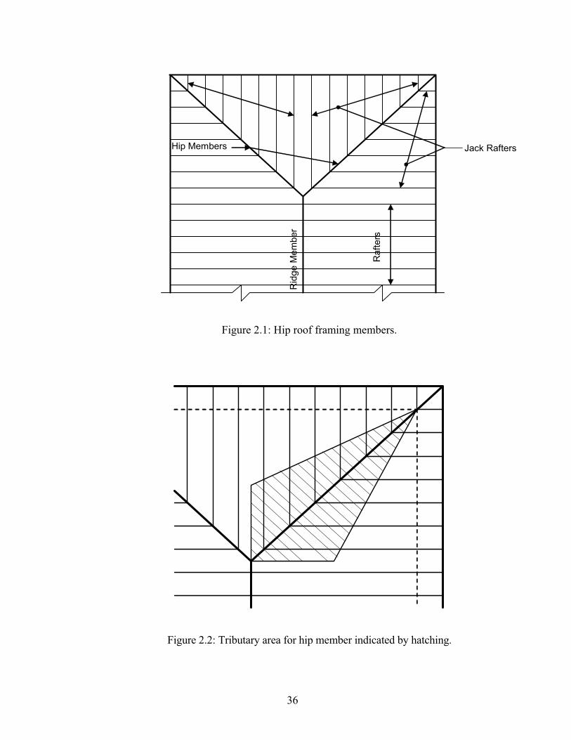
loads and connections. The hip members were analyzed as simple span beams with a triangular
load based on the tributary area. Figure 2.2 shows the tributary area for the hip members.
2.2.1 Dead Load (D)
The roof dead load of 7 psf used for design was taken from Table A1-1 of the Prescriptive
Method (AISI 2002). The dead load was applied as previously described in Section 1.1.1 and
shown in Figure 1.5.
2.2.2 Roof Live Load (Lr)
According to the Prescriptive Method, the minimum roof live load used for roof framing is 16
psf. This load was applied on the horizontal projected area of the hip member.
2.2.3 Roof Snow Load (S)
Ground snow load was considered up to a maximum of 70 psf. The roof design snow load
was determined by multiplying the ground snow load by 0.7 which is the current load determination
methodology described in the Prescriptive Method. The calculated roof snow load was then applied
vertically on the horizontally projected area.
2.2.4 Wind Load (W)
For rafter design, component and cladding (C & C) wind loads are used in load
combinations. The rafters receive wind loads from cladding which meets the definition of a
component. Wind loads applied to the hip members and supporting columns were determined
based on Main Wind Force-Resisting System (MWFRS) rather than C & C loads. Hip members are
loaded primarily from the jack rafters with a minor portion coming directly from the cladding. Hip
members also receive wind from more than surface which is another indication that the member is a
part of the MWFRS. The assumption that MWFRS loads are to be used for hip member design is
consistent with the design of load bearing wall headers which resist both gravity loads and wind
28
uplift loads from the rafters or trusses connected directly to them (ASCE 2004, ASCE 2005, AISI
2003). The supporting columns also are designed using MWFRS wind loads because they receive
load from the hip members and not the cladding. The columns also receive load from three
different roof planes. Method 2 for MWFRS from ASCE7-05 for wind speeds from 85 mph to 150
mph and exposures B and C was used to determine the wind pressures on the different planes of the
roof. The wind load is applied perpendicular to the roof planes both for downward and upward
forces.
For the development of the tables for member sizes and connections, simplifying
assumptions were made to reduce the number of different combinations of building configurations
that would be needed for the determination of wind forces. For the maximum downward wind
pressures included with dead load and snow load, a 12:12 pitch roof was used. This produces the
maximum downward force on the roof. For maximum uplift wind pressures a 24 ft. wide by 48 ft.
long building with a 3:12 pitch was used. For both uplift and downward pressures a two-story
building was used with 10 ft. tall walls at each level.
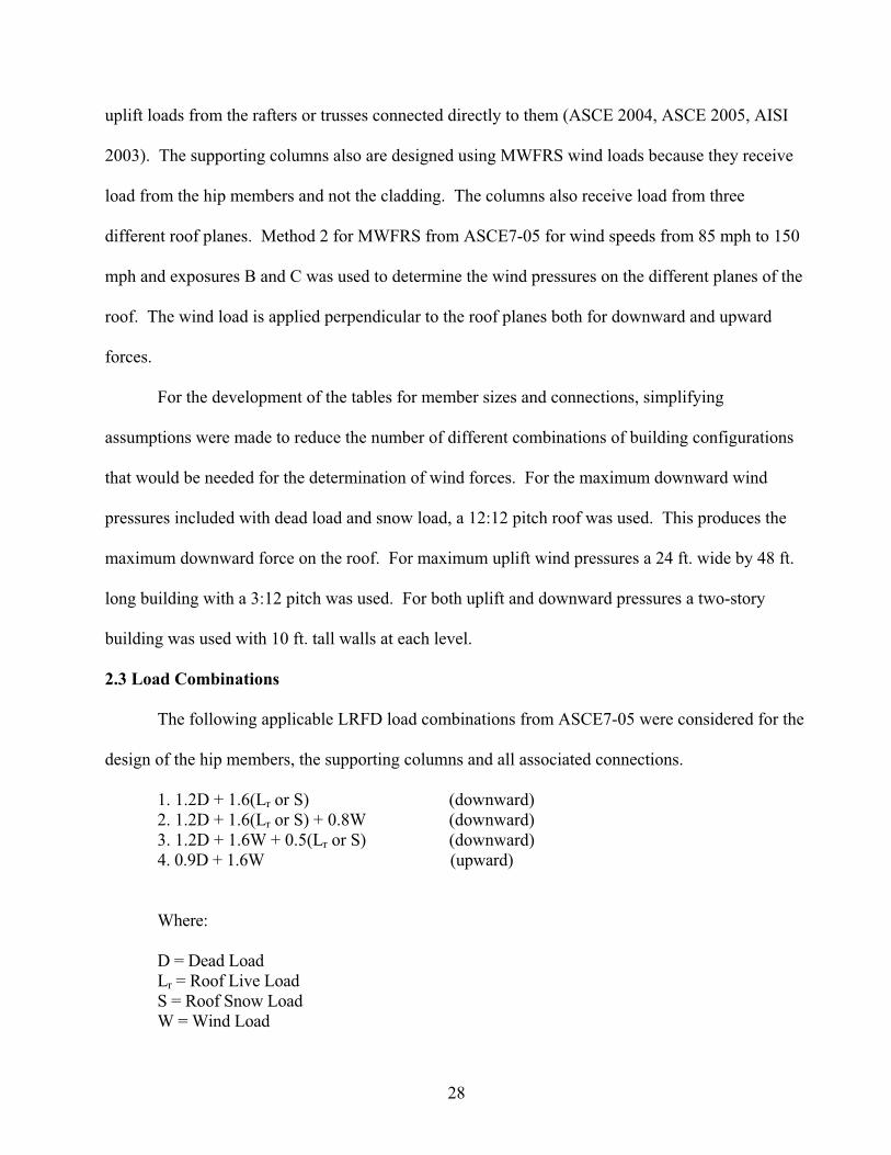
2.3 Load Combinations
The following applicable LRFD load combinations from ASCE7-05 were considered for the
design of the hip members, the supporting columns and all associated connections.
1. 1.2D + 1.6(Lr or S) (downward)
2. 1.2D + 1.6(Lr or S) + 0.8W (downward)
3. 1.2D + 1.6W + 0.5(Lr or S) (downward)
4. 0.9D + 1.6W (upward)
Where:
D = Dead Load
Lr = Roof Live Load
S = Roof Snow Load
W = Wind Load
29
2.4 Hip Member Analysis and Design
Hip members are built-up sections consisting of a C-shape and a track section as previously
described in Section 1 (Figure 1.3). These built-up sections must be the same depth members as the
rafters used so that a wall pocket will not be required in the supporting wall corner. Hip members
were limited to a maximum of 12-in deep sections with up to 2-inch wide flanges and a maximum
thickness of 97 mils. The yield strength was limited to Fy = 50 ksi because of the thickness of
material generally required and the added bending capacity provided by the higher strength
material. Only single built-up sections were considered due to the excessive width of multiple
members and the difficulty of connecting multiple members at the ridge to adequately transfer loads
from the multiple webs to the supporting column.
The hip member is considered to be laterally supported at each rafter connection. Because the
hip is in the same plane as the other roof rafters, the connections will laterally brace the top flange
under gravity loads and the bottom compression flange when uplift loads are considered. The
maximum rafter spacing according to the Prescriptive Method is 24-inches on center, therefore the
maximum unsupported length used was 34-inches (the diagonal distance between rafter connections).
The unsupported length for bending about the major axis will be the actual length of the member. The
cantilever at the overhang was conservatively ignored in calculating the maximum moment and
deflection.
Deflection criteria used for the design of the hip member is the same as required by the
Prescriptive Method. The total load deflection limit was L/180 and the snow load deflection limit was
L/240.
The maximum spans for hip members given in Table 2.1 are the maximum horizontal
projection of the hip. An example of the strength and deflection calculations for a typical hip member
30
is provided in Section A.1 of Appendix A. To determine the hip member sizes in the selection table, a
12:12 pitch roof was used for maximum downward wind pressures and a 3:12 pitch roof was used for
maximum uplift wind pressures. This was done for simplicity so that only one table need be provided
in the Prescriptive Method. Figures 2.3, 2.5 and 2.6 show the connection of hip members at the ridge
and exterior walls respectively. Tables 2.3, 2.4 and 2.5 provide screw requirements for these
connections for both gravity loads and uplift due to wind.
2.5 Hip Member Support Column
As stated previously, a column is used as a support member for the upper end of the hips to
essentially eliminate the need to consider axial forces in the hip members. This reduces the size of
the hip members that would have been required for unsupported hip framing because they are
designed for bending only rather than bending combined with axial compression. For example, the
hip member for the unsheathed 3:12 pitch roof (M230 in Figure 1.9) has 6.62 kips of axial
compression at the point of maximum moment (Table 1.3). This axial compression is eliminated
with the introduction of the support column. The columns and the connections were designed for
both gravity loads and uplift loads due to wind.
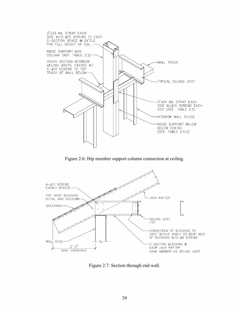
2.5.1 Column Above Ceiling
The columns above the ceiling are supported at the level of the ceiling and extend up to the
intersection of the roof ridge member and the hip members. These columns are made up of two C-
section in a box configuration. This configuration was chosen because it has a generally low
slenderness ratio and is relatively easy to construct the connections at the ceiling and the ridge. The
two C-sections are stitched together with plates as shown in Figure 2.6. The spacing was chosen to
satisfy the requirements of Section E4.2 of the AISC Specification (AISC 2001). This column
supports significant axial loads and therefore requires an interior wall or other supporting element
31
below the ceiling as described in Section 2.5.2 (Figure 2.6). A continuous load path to the
foundation at the lowest level must also be provided for both gravity and uplift loads. The column
sizes for various building widths and ground snow loads are given in Table 2.2. For simplicity, all
columns were designed based on a 12:12 pitch roof. By making this assumption only one column
selection table is required. Since there will be a very limited number of columns required on any
particular structure, this is not an overly conservative assumption. The uplift strap and screw
requirements for this column are found in Table 2.5. An example of strength calculations for a hip
support column is provided in Section A.2 of Appendix A.
2.5.2 Column Support Below Ceiling
A support for the columns above the ceiling must be provided to adequately deliver the roof
load from the hips to the foundation. This can be done by either locating a bearing wall or an
isolated column directly below the upper column with adequate axial and connection strength to
transfer gravity and uplift loads. The bearing wall will require multiple wall studs for support of the
attic column for most load conditions in addition to adequate connections to resist tension forces
produced by wind uplift. An isolated column may be made up of multiple C-shaped sections,
forming a box type section to facilitate attachment of gypsum wall board. An example of strength
calculations for a hip support column is provided in Section A.3 of Appendix A.
2.6 Connections
To adequately transfer gravity and wind uplift loads between the hip members and
supporting members, connections must be designed to resist the maximum design load as
determined by the appropriate load combinations. These connections must also be simple to
understand and construct to be appropriate for use in the Prescriptive Method (AISI 2002). The
32
connections detailed in this report are the hip member connections at the ridge and at the wall
corner and the upper column connection to the support below at the ceiling.
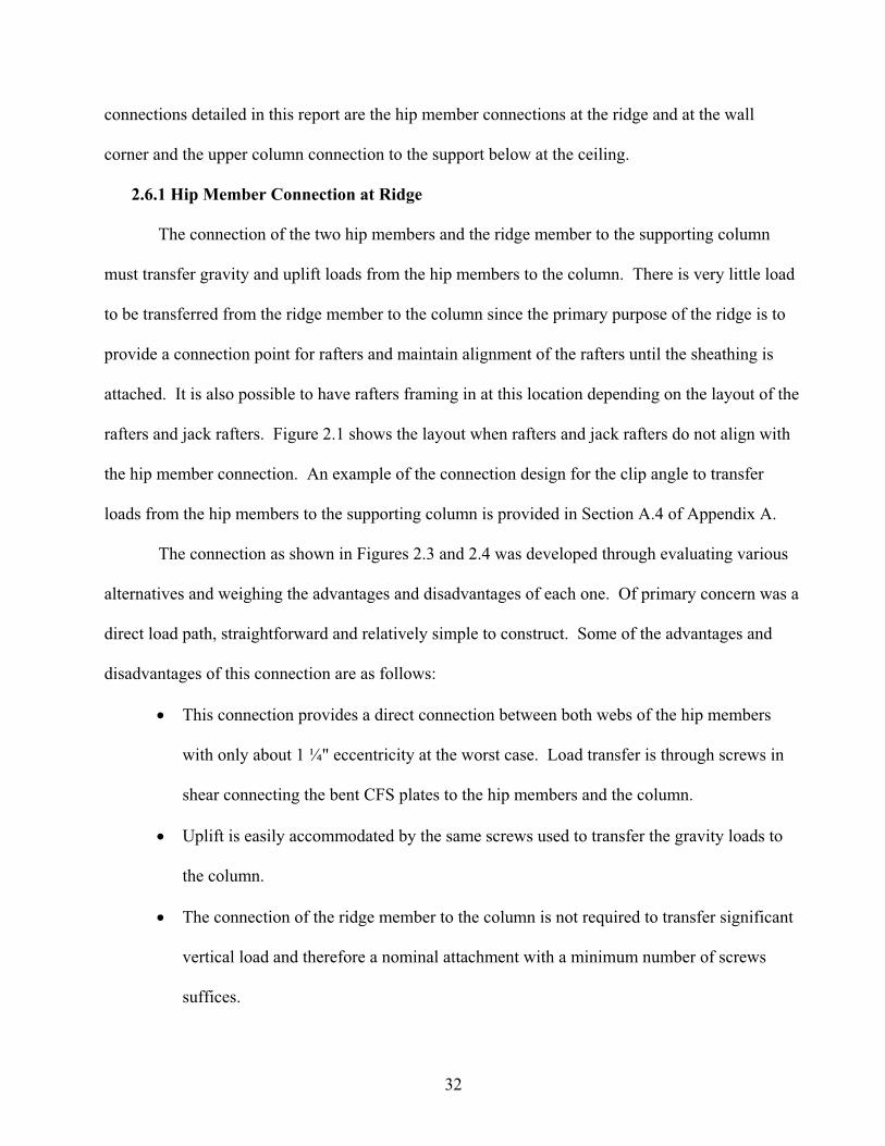
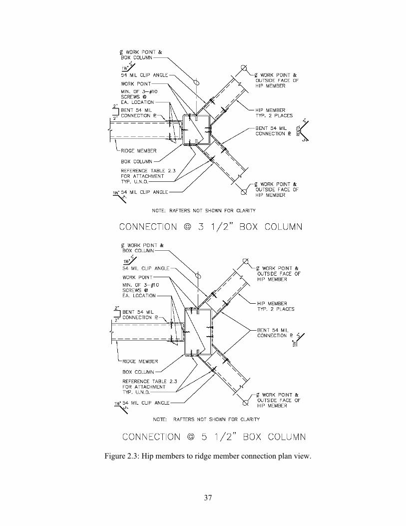
2.6.1 Hip Member Connection at Ridge
The connection of the two hip members and the ridge member to the supporting column
must transfer gravity and uplift loads from the hip members to the column. There is very little load
to be transferred from the ridge member to the column since the primary purpose of the ridge is to
provide a connection point for rafters and maintain alignment of the rafters until the sheathing is
attached. It is also possible to have rafters framing in at this location depending on the layout of the
rafters and jack rafters. Figure 2.1 shows the layout when rafters and jack rafters do not align with
the hip member connection. An example of the connection design for the clip angle to transfer
loads from the hip members to the supporting column is provided in Section A.4 of Appendix A.
The connection as shown in Figures 2.3 and 2.4 was developed through evaluating various
alternatives and weighing the advantages and disadvantages of each one. Of primary concern was a
direct load path, straightforward and relatively simple to construct. Some of the advantages and
disadvantages of this connection are as follows:
This connection provides a direct connection between both webs of the hip members
with only about 1 ¼" eccentricity at the worst case. Load transfer is through screws in
shear connecting the bent CFS plates to the hip members and the column.
Uplift is easily accommodated by the same screws used to transfer the gravity loads to
the column.
The connection of the ridge member to the column is not required to transfer significant
vertical load and therefore a nominal attachment with a minimum number of screws
suffices.
33
This connection does not allow for the rafters to come into the center of the connection
easily because of the clips and screws already at those locations.
The column is restricted to the location of the intersection of the hip members. This is
somewhat of a disadvantage because it does not allow for flexibility in locating the
column in the living space. If the column were to be allowed to be located away from
the intersection of the hip members back along the ridge member, then the ridge member
becomes a load carrying member and must be designed for bending, web crippling and
shear. Also, the connection of the hip members to the ridge member does not then easily
allow for load transfer from both webs of the hip member to the ridge member which is
especially important for the higher hip member reactions.
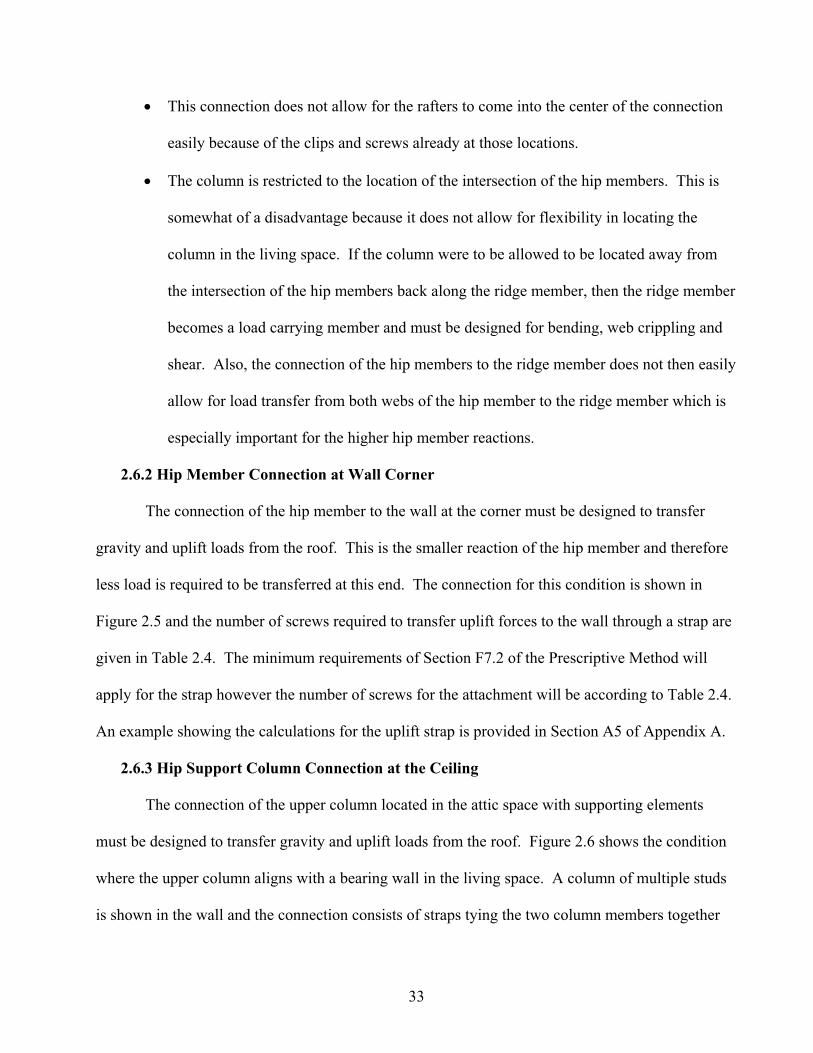
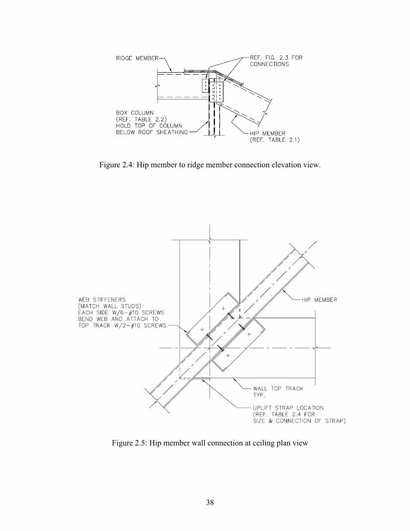
2.6.2 Hip Member Connection at Wall Corner
The connection of the hip member to the wall at the corner must be designed to transfer
gravity and uplift loads from the roof. This is the smaller reaction of the hip member and therefore
less load is required to be transferred at this end. The connection for this condition is shown in
Figure 2.5 and the number of screws required to transfer uplift forces to the wall through a strap are
given in Table 2.4. The minimum requirements of Section F7.2 of the Prescriptive Method will
apply for the strap however the number of screws for the attachment will be according to Table 2.4.
An example showing the calculations for the uplift strap is provided in Section A5 of Appendix A.
2.6.3 Hip Support Column Connection at the Ceiling
The connection of the upper column located in the attic space with supporting elements
must be designed to transfer gravity and uplift loads from the roof. Figure 2.6 shows the condition
where the upper column aligns with a bearing wall in the living space. A column of multiple studs
is shown in the wall and the connection consists of straps tying the two column members together
34
attached with screws in shear. The number of screws required for the straps are given in Table 2.5.
An example showing the calculations for the uplift strap is provided in Section A6 of Appendix A.
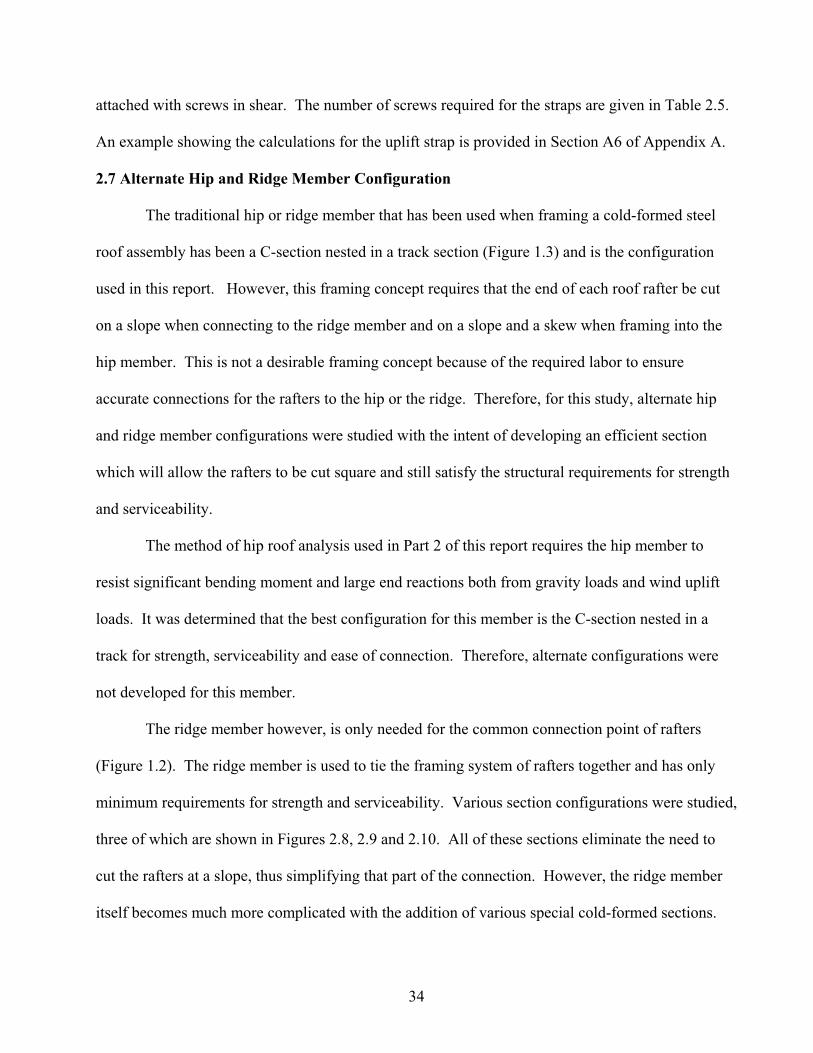
2.7 Alternate Hip and Ridge Member Configuration
The traditional hip or ridge member that has been used when framing a cold-formed steel
roof assembly has been a C-section nested in a track section (Figure 1.3) and is the configuration
used in this report. However, this framing concept requires that the end of each roof rafter be cut
on a slope when connecting to the ridge member and on a slope and a skew when framing into the
hip member. This is not a desirable framing concept because of the required labor to ensure
accurate connections for the rafters to the hip or the ridge. Therefore, for this study, alternate hip
and ridge member configurations were studied with the intent of developing an efficient section
which will allow the rafters to be cut square and still satisfy the structural requirements for strength
and serviceability.
The method of hip roof analysis used in Part 2 of this report requires the hip member to
resist significant bending moment and large end reactions both from gravity loads and wind uplift
loads. It was determined that the best configuration for this member is the C-section nested in a
track for strength, serviceability and ease of connection. Therefore, alternate configurations were
not developed for this member.
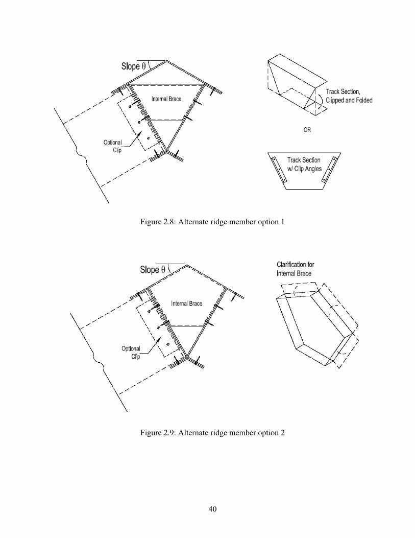
The ridge member however, is only needed for the common connection point of rafters
(Figure 1.2). The ridge member is used to tie the framing system of rafters together and has only
minimum requirements for strength and serviceability. Various section configurations were studied,
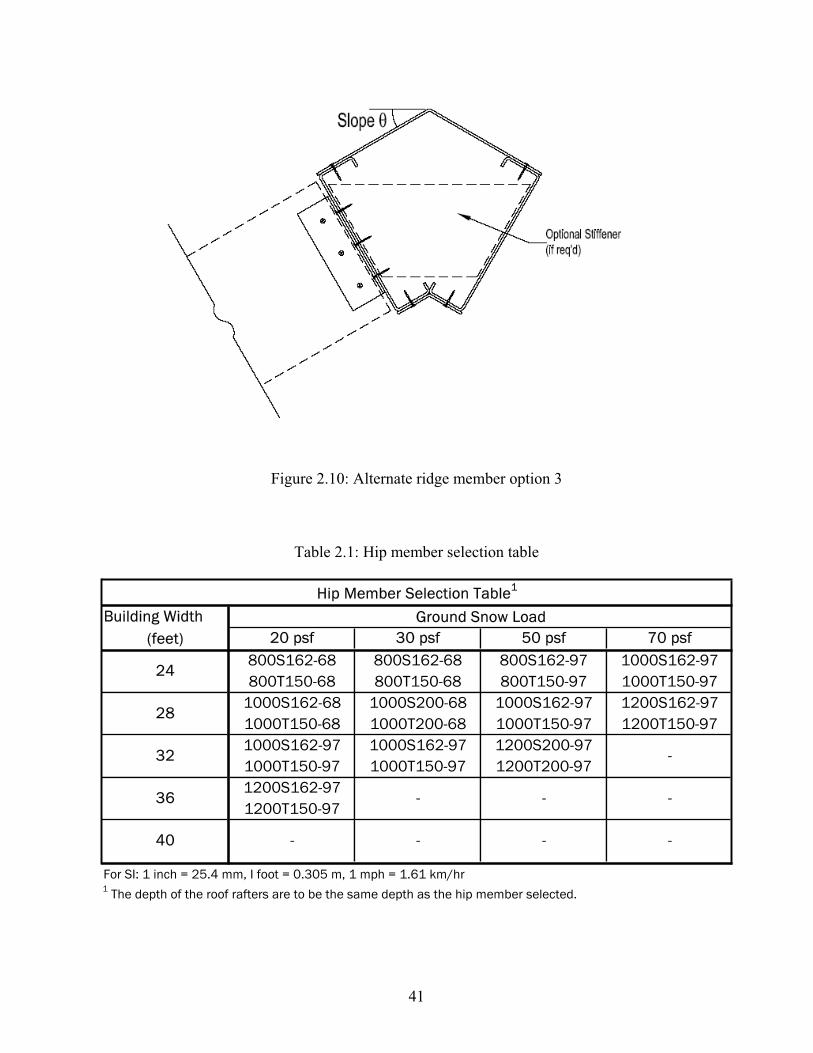
three of which are shown in Figures 2.8, 2.9 and 2.10. All of these sections eliminate the need to
cut the rafters at a slope, thus simplifying that part of the connection. However, the ridge member
itself becomes much more complicated with the addition of various special cold-formed sections.
35
The connection of the ridge member at the hip member support column (Figure 2.3) also becomes
more complicated. For these reasons it would appear that revising the ridge member to
accommodate square cuts on the ends of the rafters is not really that practical since it may actually
cost more to construct an alternate ridge member than could possibly be saved in changing from a
sloped cut to a square cut on the rafters.
2.8 Conclusions
Hip roof rafters are common means of roof framing for residential construction. However,
the Standard for Cold-Formed Steel Framing -Prescriptive Method for One and Two Family
Dwellings (American 2002) does not provide information for hip roof rafter framing. Thus, the
focus of this study was to define the design requirements for the roof rafter and to generate the
requisite tables of member sizes and connection details. The report explains the analysis and design
assumptions that were used to generate the tables and details.
The traditional hip rafter or ridge member that has been used when framing a cold-formed
steel roof assembly has been a C-section nested in a track section. This framing concept requires
that the end of each roof rafter be cut on a slope when connecting to the ridge member and on a
slope and a skew when framing into a hip member. This is not a desirable framing concept because
of the required labor to ensure accurate connections for the rafters to the hip or the ridge. Thus
alternative framing concepts were developed for the rafters to the ridge member that would
eliminate the need for the sloped connection detail. It was inconclusive whether or not an alternate
ridge member configuration would actually be more economical when the added cost of fabricating
the ridge member is considered.
36
Rid
ge M
em
ber
Hip Members Jack Rafters
Raft
ers
Figure 2.1: Hip roof framing members.
Figure 2.2: Tributary area for hip member indicated by hatching.
37
Figure 2.3: Hip members to ridge member connection plan view.
38
Figure 2.4: Hip member to ridge member connection elevation view.
Figure 2.5: Hip member wall connection at ceiling plan view
39
Figure 2.6: Hip member support column connection at ceiling.
Figure 2.7: Section through end wall.
40
Figure 2.8: Alternate ridge member option 1
Figure 2.9: Alternate ridge member option 2
41
Figure 2.10: Alternate ridge member option 3
Table 2.1: Hip member selection table
Building Width(feet) 20 psf 30 psf 50 psf 70 psf
800S162-68 800S162-68 800S162-97 1000S162-97800T150-68 800T150-68 800T150-97 1000T150-97
1000S162-68 1000S200-68 1000S162-97 1200S162-971000T150-68 1000T200-68 1000T150-97 1200T150-971000S162-97 1000S162-97 1200S200-971000T150-97 1000T150-97 1200T200-971200S162-971200T150-97
For SI: 1 inch = 25.4 mm, I foot = 0.305 m, 1 mph = 1.61 km/hr1 The depth of the roof rafters are to be the same depth as the hip member selected.
Hip Member Selection Table1
Ground Snow Load
24
28
32 -
36 - - -
-40 - - -
42
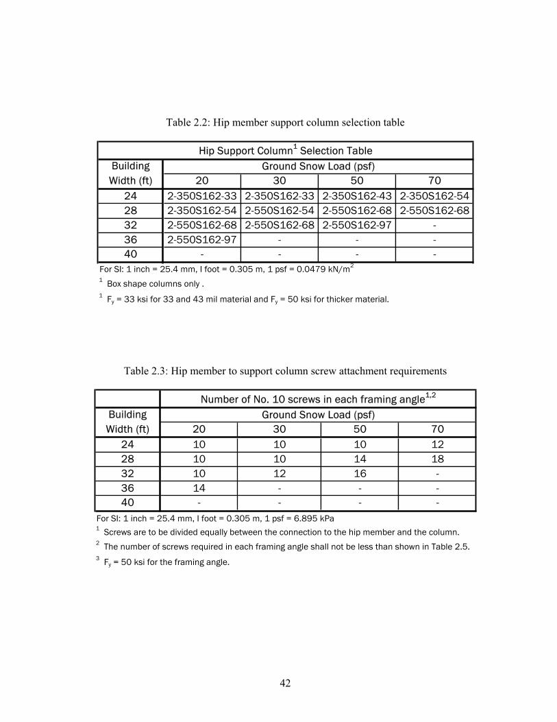
Table 2.2: Hip member support column selection table
20 30 50 7024 2-350S162-33 2-350S162-33 2-350S162-43 2-350S162-5428 2-350S162-54 2-550S162-54 2-550S162-68 2-550S162-6832 2-550S162-68 2-550S162-68 2-550S162-97 -36 2-550S162-97 - - -40 - - - -
For SI: 1 inch = 25.4 mm, I foot = 0.305 m, 1 psf = 0.0479 kN/m2
1 Box shape columns only .1 Fy = 33 ksi for 33 and 43 mil material and Fy = 50 ksi for thicker material.
Hip Support Column1 Selection TableBuilding
Width (ft)Ground Snow Load (psf)
Table 2.3: Hip member to support column screw attachment requirements
20 30 50 7024 10 10 10 1228 10 10 14 1832 10 12 16 -36 14 - - -40 - - - -
For SI: 1 inch = 25.4 mm, I foot = 0.305 m, 1 psf = 6.895 kPa1 Screws are to be divided equally between the connection to the hip member and the column.2 The number of screws required in each framing angle shall not be less than shown in Table 2.5.3 Fy = 50 ksi for the framing angle.
Building Width (ft)
Ground Snow Load (psf)Number of No. 10 screws in each framing angle1,2
43
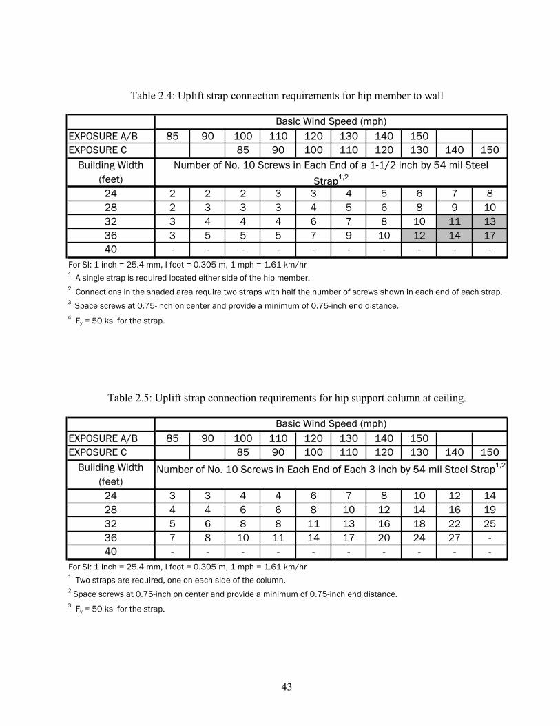
Table 2.4: Uplift strap connection requirements for hip member to wall
EXPOSURE A/B 85 90 100 110 120 130 140 150EXPOSURE C 85 90 100 110 120 130 140 150
24 2 2 2 3 3 4 5 6 7 828 2 3 3 3 4 5 6 8 9 1032 3 4 4 4 6 7 8 10 11 1336 3 5 5 5 7 9 10 12 14 1740 - - - - - - - - - -
For SI: 1 inch = 25.4 mm, I foot = 0.305 m, 1 mph = 1.61 km/hr1 A single strap is required located either side of the hip member.2 Connections in the shaded area require two straps with half the number of screws shown in each end of each strap.3 Space screws at 0.75-inch on center and provide a minimum of 0.75-inch end distance.4 Fy = 50 ksi for the strap.
Number of No. 10 Screws in Each End of a 1-1/2 inch by 54 mil Steel
Strap1,2
Basic Wind Speed (mph)
Building Width (feet)
Table 2.5: Uplift strap connection requirements for hip support column at ceiling.
EXPOSURE A/B 85 90 100 110 120 130 140 150EXPOSURE C 85 90 100 110 120 130 140 150
24 3 3 4 4 6 7 8 10 12 1428 4 4 6 6 8 10 12 14 16 1932 5 6 8 8 11 13 16 18 22 2536 7 8 10 11 14 17 20 24 27 --40 - - - - - - - - - -
For SI: 1 inch = 25.4 mm, I foot = 0.305 m, 1 mph = 1.61 km/hr1 Two straps are required, one on each side of the column.2 Space screws at 0.75-inch on center and provide a minimum of 0.75-inch end distance.3 Fy = 50 ksi for the strap.
Number of No. 10 Screws in Each End of Each 3 inch by 54 mil Steel Strap1,2Building Width (feet)
Basic Wind Speed (mph)
44
REFERENCES
American Forest & Paper Association (2001a). Commentary to the Wood Frame Construction
Manual for One- and Two-Family Dwellings. Washington, DC.
American Forest & Paper Association (2001b). Wood Frame Construction Manual for One- and
Two-Family Dwellings. Washington, DC.
American Institute of Steel Construction (AISC) (2001), Manual of Steel Construction – Load and
Resistance Factor Design, 3rd
Edition, AISC, Chicago, IL, November.
American Iron and Steel Institute (AISI) (2001), AISI, North American Specification for the Design
of Cold Formed Steel Structural Members, 2001 Edition with 2004 Supplement, American Iron and
Steel Institute, Washington, DC.
American Iron and Steel Institute (AISI) (2002), Standard for Cold-Formed Steel Framing –
Prescriptive Method for One and Two Family Dwellings, AISI, Washington, D.C.
American Iron and Steel Institute (AISI) (2003), Commentary on the Standard for Cold-Formed
Steel Framing – Prescriptive Method for One and Two Family Dwellings, AISI, Washington, D.C.
American Iron and Steel Institute (AISI) (2004a), AISI Standard for Cold-Formed Steel Framing –
Wall Stud Design, AISI, Washington, D.C.
American Iron and Steel Institute (AISI) (2004b), AISI Standard for Cold-Formed Steel Framing –
Lateral Design, AISI, Washington, D.C.
APA – The Engineered Wood Association (APA) (2004), Panel Design Specification, APA,
Tacoma, WA, March 2004.
American Society of Civil Engineers (ASCE) (2004), Guide to the Use of the Wind Load Provisions
of ASCE7-02, New York, NY.
American Society of Civil Engineers (ASCE) (2005), Minimum Design Loads for Buildings and
Other Structures, ASCE 7-05, New York, NY.
International Code Council (ICC) (2003), International Building Code, ICC, Falls Church, VA.
RISA-3D Software (RISA 2005), RISA-3D Version 5.15, RISA Technologies, Foothill Ranch, CA.
RSG Software (RSG) (2005), CFS Version 5.0.2, RSG Software, Inc., Lee’s Summit, MO.
Stalnaker, Judith J., and Harris, Ernest C. (1999), Structural Design in Wood, 2nd
Edition, Kluwer
Academic Publishers.
Yu, Wei-Wen (2000). Cold-Formed Steel Design, 3rd
Edition, New York, NY, John Wiley & Sons,
Inc.
45
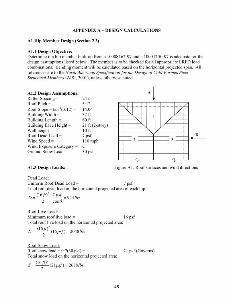
APPENDIX A – DESIGN CALCULATIONS
A1 Hip Member Design (Section 2.3)
A1.1 Design Objective:
Determine if a hip member built-up from a 1000S162-97 and a 1000T150-97 is adequate for the
design assumptions listed below. The member is to be checked for all appropriate LRFD load
combinations. Bending moment will be calculated based on the horizontal projected span. All
references are to the North American Specification for the Design of Cold-Formed Steel
Structural Members (AISI, 2001), unless otherwise noted.
A1.2 Design Assumptions:
Rafter Spacing = 24 in
Roof Pitch = 3:12
Roof Slope = tan-1
(3:12) = 14.04
Building Width = 32 ft
Building Length = 60 ft
Building Eave Height = 21 ft (2-story)
Wall height = 10 ft
Roof Dead Load = 7 psf
Wind Speed = 110 mph
Wind Exposure Category = C
Ground Snow Load = 30 psf
A1.3 Design Loads: Figure A1: Roof surfaces and wind directions
Dead Load:
Uniform Roof Dead Load = 7 psf
Total roof dead load on the horizontal projected area of each hip: 2(16 ) 7
9242 cos
ft psfD lbs
Roof Live Load:
Minimum roof live load = 16 psf
Total roof live load on the horizontal projected area: 2(16 )
(16 ) 20482
r
ftL psf lbs
Roof Snow Load:
Roof snow load = 0.7(30 psf) = 21 psf (Governs)
Total snow load on the horizontal projected area: 2(16 )
(21 ) 26882
ftS psf lbs
1
2 3
A
B
46
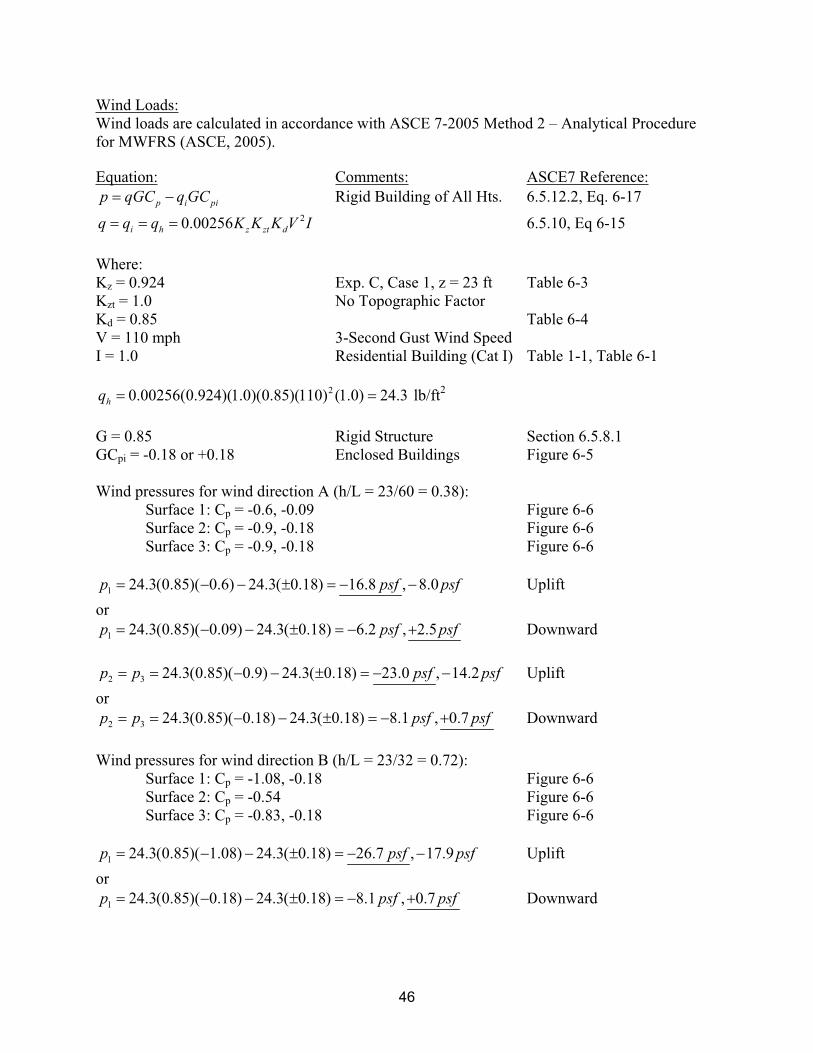
Wind Loads:
Wind loads are calculated in accordance with ASCE 7-2005 Method 2 – Analytical Procedure
for MWFRS (ASCE, 2005).
Equation: Comments: ASCE7 Reference:
p i pip qGC q GC Rigid Building of All Hts. 6.5.12.2, Eq. 6-17
20.00256i h z zt dq q q K K K V I 6.5.10, Eq 6-15
Where:
Kz = 0.924 Exp. C, Case 1, z = 23 ft Table 6-3
Kzt = 1.0 No Topographic Factor
Kd = 0.85 Table 6-4
V = 110 mph 3-Second Gust Wind Speed
I = 1.0 Residential Building (Cat I) Table 1-1, Table 6-1
20.00256(0.924)(1.0)(0.85)(110) (1.0) 24.3hq lb/ft2
G = 0.85 Rigid Structure Section 6.5.8.1
GCpi = -0.18 or +0.18 Enclosed Buildings Figure 6-5
Wind pressures for wind direction A (h/L = 23/60 = 0.38):
Surface 1: Cp = -0.6, -0.09 Figure 6-6
Surface 2: Cp = -0.9, -0.18 Figure 6-6
Surface 3: Cp = -0.9, -0.18 Figure 6-6
1 24.3(0.85)( 0.6) 24.3( 0.18) 16.8 , 8.0p psf psf Uplift
or
1 24.3(0.85)( 0.09) 24.3( 0.18) 6.2 , 2.5p psf psf Downward
2 3 24.3(0.85)( 0.9) 24.3( 0.18) 23.0 , 14.2p p psf psf Uplift
or
2 3 24.3(0.85)( 0.18) 24.3( 0.18) 8.1 , 0.7p p psf psf Downward
Wind pressures for wind direction B (h/L = 23/32 = 0.72):
Surface 1: Cp = -1.08, -0.18 Figure 6-6
Surface 2: Cp = -0.54 Figure 6-6
Surface 3: Cp = -0.83, -0.18 Figure 6-6
1 24.3(0.85)( 1.08) 24.3( 0.18) 26.7 , 17.9p psf psf Uplift
or
1 24.3(0.85)( 0.18) 24.3( 0.18) 8.1 , 0.7p psf psf Downward
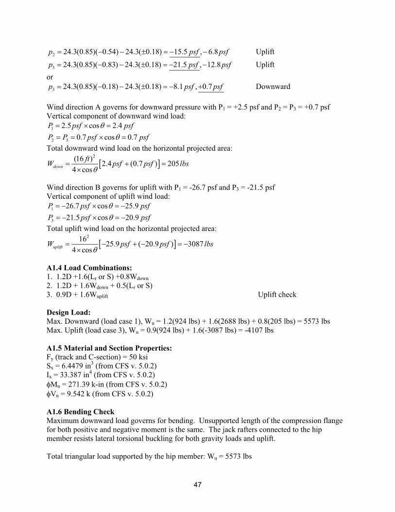
47
2 24.3(0.85)( 0.54) 24.3( 0.18) 15.5 , 6.8p psf psf Uplift
3 24.3(0.85)( 0.83) 24.3( 0.18) 21.5 , 12.8p psf psf Uplift
or
3 24.3(0.85)( 0.18) 24.3( 0.18) 8.1 , 0.7p psf psf Downward
Wind direction A governs for downward pressure with P1 = +2.5 psf and P2 = P3 = +0.7 psf
Vertical component of downward wind load:
1 2.5 cos 2.4P psf psf
2 3 0.7 cos 0.7P P psf psf
Total downward wind load on the horizontal projected area: 2(16 )
2.4 (0.7 ) 2054 cos
down
ftW psf psf lbs
Wind direction B governs for uplift with P1 = -26.7 psf and P3 = -21.5 psf
Vertical component of uplift wind load:
1 26.7 cos 25.9P psf psf
3 21.5 cos 20.9P psf psf
Total uplift wind load on the horizontal projected area: 216
25.9 ( 20.9 ) 30874 cos
upliftW psf psf lbs
A1.4 Load Combinations:
1. 1.2D +1.6(Lr or S) +0.8Wdown
2. 1.2D + 1.6Wdown + 0.5(Lr or S)
3. 0.9D + 1.6Wuplift Uplift check
Design Load:
Max. Downward (load case 1), Wu = 1.2(924 lbs) + 1.6(2688 lbs) + 0.8(205 lbs) = 5573 lbs
Max. Uplift (load case 3), Wu = 0.9(924 lbs) + 1.6(-3087 lbs) = -4107 lbs
A1.5 Material and Section Properties:
Fy (track and C-section) = 50 ksi
Sx = 6.4479 in3 (from CFS v. 5.0.2)
Ix = 33.387 in4 (from CFS v. 5.0.2)
Mn = 271.39 k-in (from CFS v. 5.0.2)
Vn = 9.542 k (from CFS v. 5.0.2)
A1.6 Bending Check
Maximum downward load governs for bending. Unsupported length of the compression flange
for both positive and negative moment is the same. The jack rafters connected to the hip
member resists lateral torsional buckling for both gravity loads and uplift.
Total triangular load supported by the hip member: Wu = 5573 lbs
48
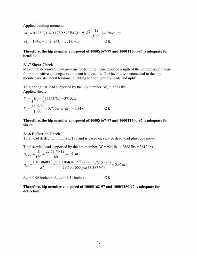
Applied bending moment:
120.128 0.128(5573 )(16 ) 2 194
1000u uM W L lbs ft k in
194 271u nM k in M k in OK
Therefore, the hip member composed of 1000S167-97 and 1000T1500-97 is adequate for
bending.
A1.7 Shear Check
Maximum downward load governs for bending. Unsupported length of the compression flange
for both positive and negative moment is the same. The jack rafters connected to the hip
member resists lateral torsional buckling for both gravity loads and uplift.
Total triangular load supported by the hip member: Wu = 5573 lbs
Applied shear:
2 2(5573 ) 3715
3 3u uV W lbs lbs
37153.715 9.54
1000u n
lbsV k V k OK
Therefore, the hip member composed of 1000S167-97 and 1000T1500-97 is adequate for
shear.
A1.8 Deflection Check
Total load deflection limit is L/180 and is based on service dead load plus roof snow.
Total service load supported by the hip member: W = 924 lbs + 2688 lbs = 3612 lbs
22.63 121.51
180 180allow
L ftin
3 3
4
0.01304 0.01304(3612 )(22.63 ) (1728)0.96
29,500,000 (33.387 )tot
x
WL lbs ftin
EI psi in
tot = 0.96 inches < allow = 1.51 inches OK
Therefore, hip member composed of 1000S162-97 and 1000T150-97 is adequate for
deflection.
49
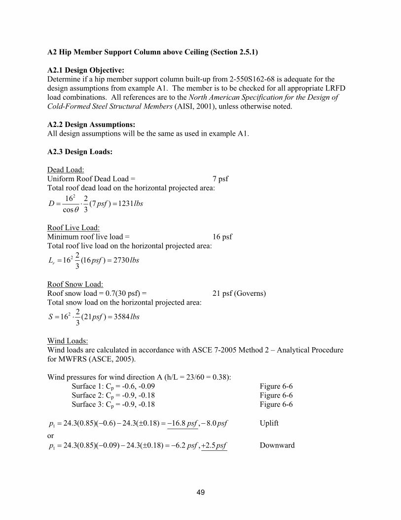
A2 Hip Member Support Column above Ceiling (Section 2.5.1)
A2.1 Design Objective:
Determine if a hip member support column built-up from 2-550S162-68 is adequate for the
design assumptions from example A1. The member is to be checked for all appropriate LRFD
load combinations. All references are to the North American Specification for the Design of
Cold-Formed Steel Structural Members (AISI, 2001), unless otherwise noted.
A2.2 Design Assumptions:
All design assumptions will be the same as used in example A1.
A2.3 Design Loads:
Dead Load:
Uniform Roof Dead Load = 7 psf
Total roof dead load on the horizontal projected area: 216 2
(7 ) 1231cos 3
D psf lbs
Roof Live Load:
Minimum roof live load = 16 psf
Total roof live load on the horizontal projected area:
2 216 (16 ) 2730
3rL psf lbs
Roof Snow Load:
Roof snow load = 0.7(30 psf) = 21 psf (Governs)
Total snow load on the horizontal projected area:
2 216 (21 ) 3584
3S psf lbs
Wind Loads:
Wind loads are calculated in accordance with ASCE 7-2005 Method 2 – Analytical Procedure
for MWFRS (ASCE, 2005).
Wind pressures for wind direction A (h/L = 23/60 = 0.38):
Surface 1: Cp = -0.6, -0.09 Figure 6-6
Surface 2: Cp = -0.9, -0.18 Figure 6-6
Surface 3: Cp = -0.9, -0.18 Figure 6-6
1 24.3(0.85)( 0.6) 24.3( 0.18) 16.8 , 8.0p psf psf Uplift
or
1 24.3(0.85)( 0.09) 24.3( 0.18) 6.2 , 2.5p psf psf Downward
50
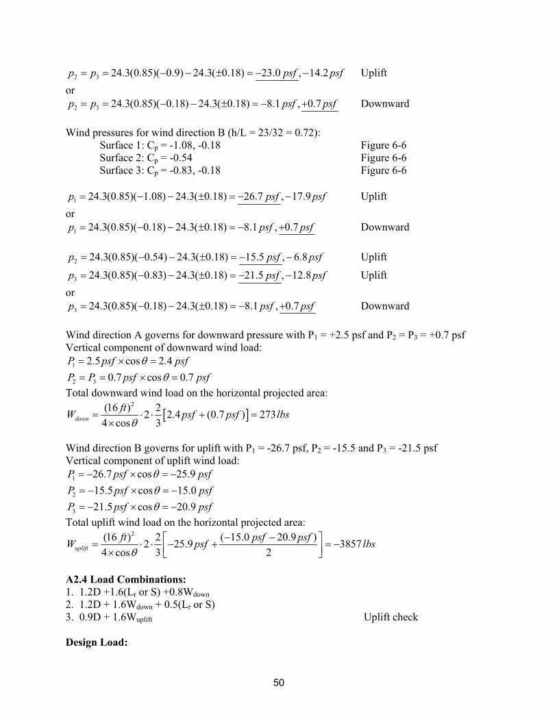
2 3 24.3(0.85)( 0.9) 24.3( 0.18) 23.0 , 14.2p p psf psf Uplift
or
2 3 24.3(0.85)( 0.18) 24.3( 0.18) 8.1 , 0.7p p psf psf Downward
Wind pressures for wind direction B (h/L = 23/32 = 0.72):
Surface 1: Cp = -1.08, -0.18 Figure 6-6
Surface 2: Cp = -0.54 Figure 6-6
Surface 3: Cp = -0.83, -0.18 Figure 6-6
1 24.3(0.85)( 1.08) 24.3( 0.18) 26.7 , 17.9p psf psf Uplift
or
1 24.3(0.85)( 0.18) 24.3( 0.18) 8.1 , 0.7p psf psf Downward
2 24.3(0.85)( 0.54) 24.3( 0.18) 15.5 , 6.8p psf psf Uplift
3 24.3(0.85)( 0.83) 24.3( 0.18) 21.5 , 12.8p psf psf Uplift
or
3 24.3(0.85)( 0.18) 24.3( 0.18) 8.1 , 0.7p psf psf Downward
Wind direction A governs for downward pressure with P1 = +2.5 psf and P2 = P3 = +0.7 psf
Vertical component of downward wind load:
1 2.5 cos 2.4P psf psf
2 3 0.7 cos 0.7P P psf psf
Total downward wind load on the horizontal projected area: 2(16 ) 2
2 2.4 (0.7 ) 2734 cos 3
down
ftW psf psf lbs
Wind direction B governs for uplift with P1 = -26.7 psf, P2 = -15.5 and P3 = -21.5 psf
Vertical component of uplift wind load:
1 26.7 cos 25.9P psf psf
2 15.5 cos 15.0P psf psf
3 21.5 cos 20.9P psf psf
Total uplift wind load on the horizontal projected area: 2(16 ) 2 ( 15.0 20.9 )
2 25.9 38574 cos 3 2
uplift
ft psf psfW psf lbs
A2.4 Load Combinations:
1. 1.2D +1.6(Lr or S) +0.8Wdown
2. 1.2D + 1.6Wdown + 0.5(Lr or S)
3. 0.9D + 1.6Wuplift Uplift check
Design Load:
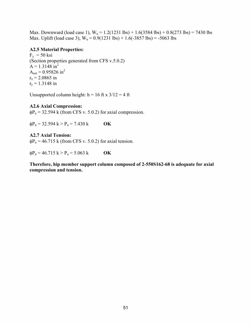
51
Max. Downward (load case 1), Wu = 1.2(1231 lbs) + 1.6(3584 lbs) + 0.8(273 lbs) = 7430 lbs
Max. Uplift (load case 3), Wu = 0.9(1231 lbs) + 1.6(-3857 lbs) = -5063 lbs
A2.5 Material Properties:
Fy = 50 ksi
(Section properties generated from CFS v.5.0.2)
A = 1.3148 in2
Anet = 0.95826 in2
rx = 2.0865 in
ry = 1.3148 in
Unsupported column height: h = 16 ft x 3/12 = 4 ft
A2.6 Axial Compression:
Pn = 32.594 k (from CFS v. 5.0.2) for axial compression.
Pn = 32.594 k > Pu = 7.430 k OK
A2.7 Axial Tension:
Pn = 46.715 k (from CFS v. 5.0.2) for axial tension.
Pn = 46.715 k > Pu = 5.063 k OK
Therefore, hip member support column composed of 2-550S162-68 is adequate for axial
compression and tension.
52
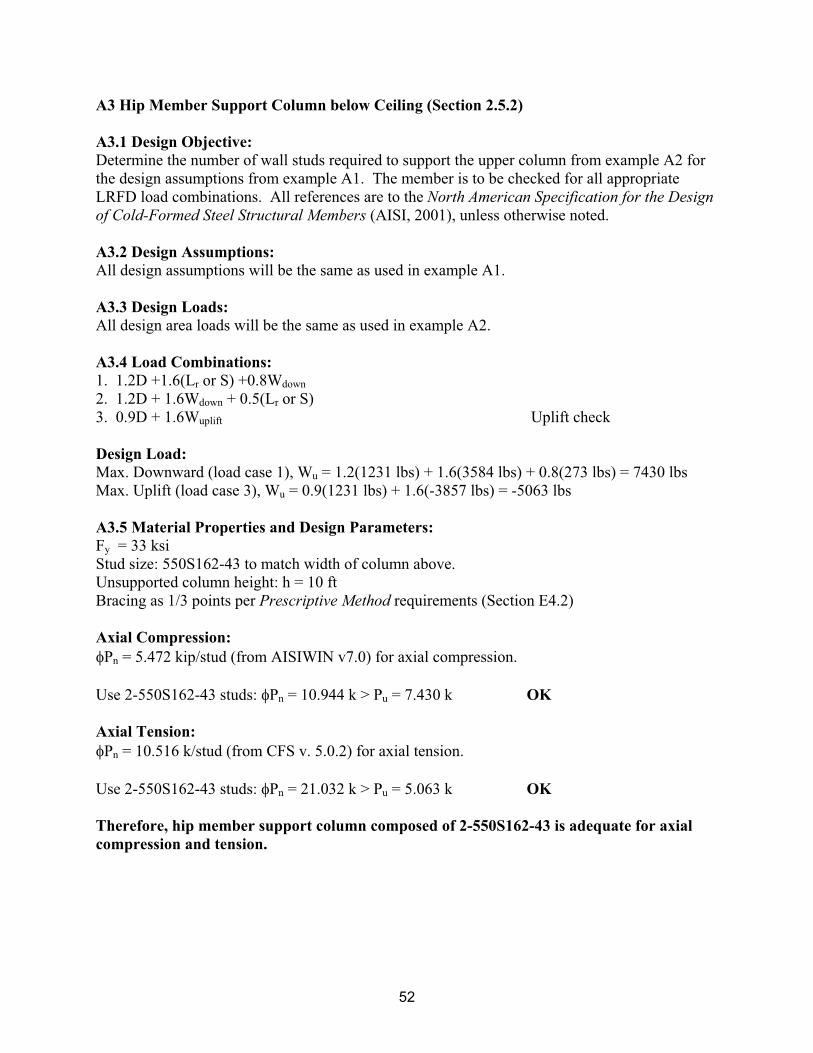
A3 Hip Member Support Column below Ceiling (Section 2.5.2)
A3.1 Design Objective:
Determine the number of wall studs required to support the upper column from example A2 for
the design assumptions from example A1. The member is to be checked for all appropriate
LRFD load combinations. All references are to the North American Specification for the Design
of Cold-Formed Steel Structural Members (AISI, 2001), unless otherwise noted.
A3.2 Design Assumptions:
All design assumptions will be the same as used in example A1.
A3.3 Design Loads:
All design area loads will be the same as used in example A2.
A3.4 Load Combinations:
1. 1.2D +1.6(Lr or S) +0.8Wdown
2. 1.2D + 1.6Wdown + 0.5(Lr or S)
3. 0.9D + 1.6Wuplift Uplift check
Design Load:
Max. Downward (load case 1), Wu = 1.2(1231 lbs) + 1.6(3584 lbs) + 0.8(273 lbs) = 7430 lbs
Max. Uplift (load case 3), Wu = 0.9(1231 lbs) + 1.6(-3857 lbs) = -5063 lbs
A3.5 Material Properties and Design Parameters:
Fy = 33 ksi
Stud size: 550S162-43 to match width of column above.
Unsupported column height: h = 10 ft
Bracing as 1/3 points per Prescriptive Method requirements (Section E4.2)
Axial Compression:
Pn = 5.472 kip/stud (from AISIWIN v7.0) for axial compression.
Use 2-550S162-43 studs: Pn = 10.944 k > Pu = 7.430 k OK
Axial Tension:
Pn = 10.516 k/stud (from CFS v. 5.0.2) for axial tension.
Use 2-550S162-43 studs: Pn = 21.032 k > Pu = 5.063 k OK
Therefore, hip member support column composed of 2-550S162-43 is adequate for axial
compression and tension.
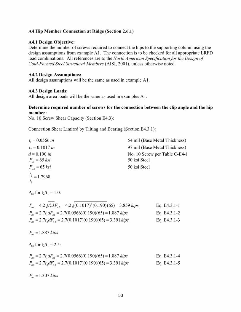
53
A4 Hip Member Connection at Ridge (Section 2.6.1)
A4.1 Design Objective:
Determine the number of screws required to connect the hips to the supporting column using the
design assumptions from example A1. The connection is to be checked for all appropriate LRFD
load combinations. All references are to the North American Specification for the Design of
Cold-Formed Steel Structural Members (AISI, 2001), unless otherwise noted.
A4.2 Design Assumptions:
All design assumptions will be the same as used in example A1.
A4.3 Design Loads:
All design area loads will be the same as used in examples A1.
Determine required number of screws for the connection between the clip angle and the hip
member:
No. 10 Screw Shear Capacity (Section E4.3):
Connection Shear Limited by Tilting and Bearing (Section E4.3.1):
1 0.0566t in 54 mil (Base Metal Thickness)
2 0.1017t in 97 mil (Base Metal Thickness)
d = 0.190 in No. 10 Screw per Table C-E4-1
1 65uF ksi 50 ksi Steel
2 65uF ksi 50 ksi Steel
2
1
1.7968t
t
Pns for t2/t1 = 1.0:
3 3
2 24.2 4.2 (0.1017) (0.190)(65) 3.859ns uP t d F kips Eq. E4.3.1-1
1 12.7 2.7(0.0566)(0.190)(65) 1.887ns uP t dF kips Eq. E4.3.1-2
2 22.7 2.7(0.1017)(0.190)(65) 3.391ns uP t dF kips Eq. E4.3.1-3
1.887nsP kips
Pns for t2/t1 = 2.5:
1 12.7 2.7(0.0566)(0.190)(65) 1.887ns uP t dF kips Eq. E4.3.1-4
2 22.7 2.7(0.1017)(0.190)(65) 3.391ns uP t dF kips Eq. E4.3.1-5
1.307nsP kips
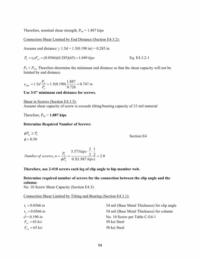
54
Therefore, nominal shear strength, Pns = 1.887 kips
Connection Shear Limited by End Distance (Section E4.3.2):
Assume end distance > 1.5d = 1.5(0.190 in) = 0.285 in
1 1 (0.0566)(0.285)(65) 1.049n uP t eF kips Eq. E4.3.2-1
Pn < Pns, Therefore determine the minimum end distance so that the shear capacity will not be
limited by end distance.
min
1.8871.5 1.5(0.190) 0.747
0.726
ns
n
Pe d in
P
Use 3/4” minimum end distance for screws.
Shear in Screws (Section E4.3.3):
Assume shear capacity of screw is exceeds tilting/bearing capacity of 33 mil material
Therefore, Pns = 1.887 kips
Determine Required Number of Screws:
0.50
ns uP PSection E4
2 15.573
3 2, 2.00.5(1.887 )
u
n
kipsP
Number of screws nP kips
Therefore, use 2-#10 screws each leg of clip angle to hip member web.
Determine required number of screws for the connection between the clip angle and the
column:
No. 10 Screw Shear Capacity (Section E4.3):
Connection Shear Limited by Tilting and Bearing (Section E4.3.1):
1 0.0566t in 54 mil (Base Metal Thickness) for clip angle
2 0.0566t in 54 mil (Base Metal Thickness) for column
d = 0.190 in No. 10 Screw per Table C-E4-1
1 65uF ksi 50 ksi Steel
2 65uF ksi 50 ksi Steel
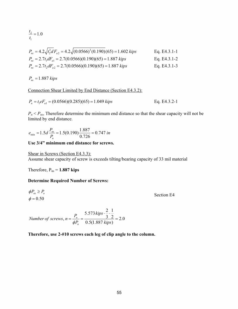
55
2
1
1.0t
t
3 3
2 24.2 4.2 (0.0566) (0.190)(65) 1.602ns uP t d F kips Eq. E4.3.1-1
1 12.7 2.7(0.0566)(0.190)(65) 1.887ns uP t dF kips Eq. E4.3.1-2
2 22.7 2.7(0.0566)(0.190)(65) 1.887ns uP t dF kips Eq. E4.3.1-3
1.887nsP kips
Connection Shear Limited by End Distance (Section E4.3.2):
1 1 (0.0566)(0.285)(65) 1.049n uP t eF kips Eq. E4.3.2-1
Pn < Pns, Therefore determine the minimum end distance so that the shear capacity will not be
limited by end distance.
min
1.8871.5 1.5(0.190) 0.747
0.726
ns
n
Pe d in
P
Use 3/4” minimum end distance for screws.
Shear in Screws (Section E4.3.3):
Assume shear capacity of screw is exceeds tilting/bearing capacity of 33 mil material
Therefore, Pns = 1.887 kips
Determine Required Number of Screws:
0.50
ns uP PSection E4
2 15.573
3 2, 2.00.5(1.887 )
u
n
kipsP
Number of screws nP kips
Therefore, use 2-#10 screws each leg of clip angle to the column.
56
A5 Hip Member Connection at Wall Corner (Section 2.6.2)
A5.1 Design Objective:
Determine the number of screws required to connect the hips to the supporting wall with a
holdown strap for uplift loads using the design assumptions from example A1. The connection is
to be checked for all appropriate LRFD load combinations. All references are to the North
American Specification for the Design of Cold-Formed Steel Structural Members (AISI, 2001),
unless otherwise noted.
A5.2 Design Assumptions:
All design assumptions will be the same as used in example A1. Assume that the wall studs are
33 mil thickness and Fy = 33 ksi material since this is the minimum requirements for these
members based on the Prescriptive Method.
A5.3 Design Loads:
All design area loads will be the same as used in example A1.
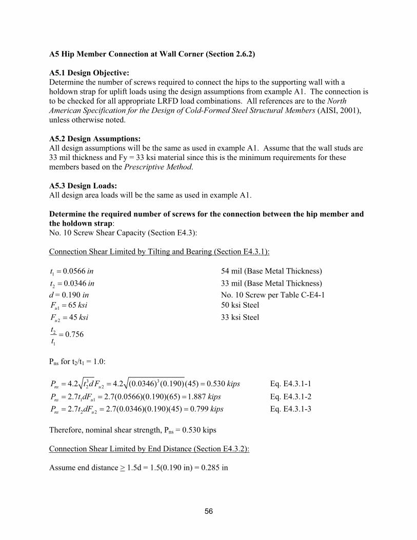
Determine the required number of screws for the connection between the hip member and
the holdown strap:
No. 10 Screw Shear Capacity (Section E4.3):
Connection Shear Limited by Tilting and Bearing (Section E4.3.1):
1 0.0566t in 54 mil (Base Metal Thickness)
2 0.0346t in 33 mil (Base Metal Thickness)
d = 0.190 in No. 10 Screw per Table C-E4-1
1 65uF ksi 50 ksi Steel
2 45uF ksi 33 ksi Steel
2
1
0.756t
t
Pns for t2/t1 = 1.0:
3 3
2 24.2 4.2 (0.0346) (0.190)(45) 0.530ns uP t d F kips Eq. E4.3.1-1
1 12.7 2.7(0.0566)(0.190)(65) 1.887ns uP t dF kips Eq. E4.3.1-2
2 22.7 2.7(0.0346)(0.190)(45) 0.799ns uP t dF kips Eq. E4.3.1-3
Therefore, nominal shear strength, Pns = 0.530 kips
Connection Shear Limited by End Distance (Section E4.3.2):
Assume end distance > 1.5d = 1.5(0.190 in) = 0.285 in
57
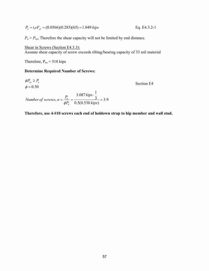
1 1 (0.0566)(0.285)(65) 1.049n uP t eF kips Eq. E4.3.2-1
Pn > Pns, Therefore the shear capacity will not be limited by end distance.
Shear in Screws (Section E4.3.3):
Assume shear capacity of screw exceeds tilting/bearing capacity of 33 mil material
Therefore, Pns = 518 kips
Determine Required Number of Screws:
0.50
ns uP PSection E4
13.087
3, 3.90.5(0.530 )
u
n
kipsP
Number of screws nP kips
Therefore, use 4-#10 screws each end of holdown strap to hip member and wall stud.
58
A6 Hip Support Column Connection at Ceiling (Section 2.6.3)
A6.1 Design Objective:
Determine the number of screws required to connect the upper hip member support column to a
column below the ceiling with holdown straps for uplift loads using the design assumptions from
example A1. The connection is to be checked for all appropriate LRFD load combinations. All
references are to the North American Specification for the Design of Cold-Formed Steel
Structural Members (AISI, 2001), unless otherwise noted.
A6.2 Design Assumptions:
All design assumptions will be the same as used in example A1. Assume that the wall studs are
33 mil thickness and Fy = 33 ksi material since this is the minimum requirements for these
members based on the Prescriptive Method.
A6.3 Design Loads:
All design area loads will be the same as used in example A1.
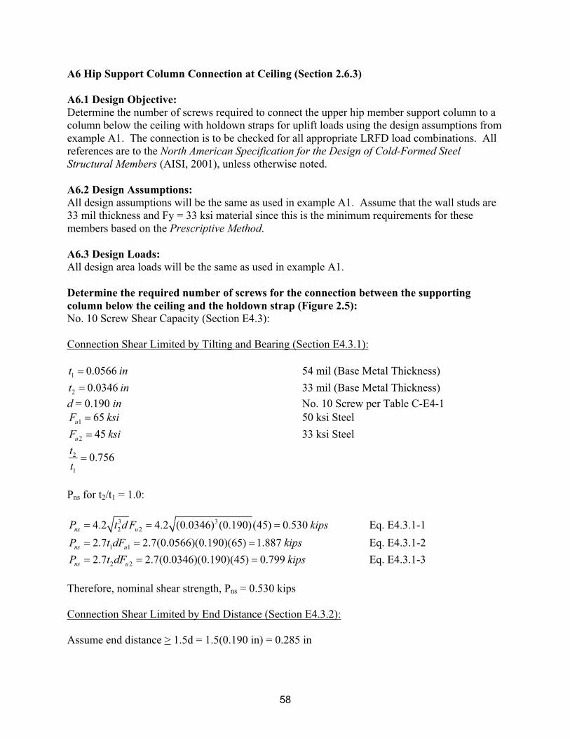
Determine the required number of screws for the connection between the supporting
column below the ceiling and the holdown strap (Figure 2.5):
No. 10 Screw Shear Capacity (Section E4.3):
Connection Shear Limited by Tilting and Bearing (Section E4.3.1):
1 0.0566t in 54 mil (Base Metal Thickness)
2 0.0346t in 33 mil (Base Metal Thickness)
d = 0.190 in No. 10 Screw per Table C-E4-1
1 65uF ksi 50 ksi Steel
2 45uF ksi 33 ksi Steel
2
1
0.756t
t
Pns for t2/t1 = 1.0:
3 3
2 24.2 4.2 (0.0346) (0.190)(45) 0.530ns uP t d F kips Eq. E4.3.1-1
1 12.7 2.7(0.0566)(0.190)(65) 1.887ns uP t dF kips Eq. E4.3.1-2
2 22.7 2.7(0.0346)(0.190)(45) 0.799ns uP t dF kips Eq. E4.3.1-3
Therefore, nominal shear strength, Pns = 0.530 kips
Connection Shear Limited by End Distance (Section E4.3.2):
Assume end distance > 1.5d = 1.5(0.190 in) = 0.285 in
59
1 1 (0.0566)(0.285)(65) 1.049n uP t eF kips Eq. E4.3.2-1
Pn > Pns, Therefore the shear capacity will not be limited by end distance.
Shear in Screws (Section E4.3.3):
Assume shear capacity of screw exceeds tilting/bearing capacity of 33 mil material
Therefore, Pns = 518 kips
Determine Required Number of Screws:
0.50
ns uP PSection E4
15.063
2, 9.50.5(0.530 )
u
n
kipsP
Number of screws nP kips
Therefore, use 10-#10 screws each end of holdown straps to hip member and wall stud.
1201 15th Street, NW
Suite 320
Washington, DC 20005
www.steelframing.org
American Iron and Steel Institute
1140 Connecticut Avenue, NW
Suite 705
Washington, DC 20036
www.steel.org
Re
se
arc
h R
ep
ort
RP
-06
-2