DESIGN ,ANALYSIS &COMPARISON OF VARIOUS CONTROLLERS FOR DC MOTOR SPEED CONTROL
34
DESIGN ,ANALYSIS &COMPARISON OF VARIOUS CONTROLLERS FOR DC MOTOR SPEED CONTROL Presented By VARUN K [email protected]
-
Upload
varun-kambrath -
Category
Technology
-
view
202 -
download
2
Transcript of DESIGN ,ANALYSIS &COMPARISON OF VARIOUS CONTROLLERS FOR DC MOTOR SPEED CONTROL

DESIGN ,ANALYSIS
&COMPARISON OF VARIOUS
CONTROLLERS FOR DC
MOTOR SPEED CONTROL
Presented By
VARUN [email protected]

INTRODUCTION
• A DC motor is any of a class of electrical machines that converts direct current electrical power into mechanical power.
• Applications: Lathes ,Drills, Boring mill, shapers, Spinning and Weaving machines, Electric traction, Cranes etc.
• How to choose DC motor: 1.How fast we want to move
2.Weight,size
3.cost and size
• Parameters:
b)Torque a)Rated speed

MODELLING

MODELLING

MODELLING

BLOCK DIAGRAM

DC MOTOR CHARACTERISTICS
• J=0.01 kgm2
• B=0.1 Nms
• Kb=0.01
• Kt=1.25
• R=1 ohm
• L=0.5 H
• Operating Voltage:12-15v
• speed:140-160rpm (1V12 rpm)
1.25
0.005 s^2 + 0.06 s + 0.1125OT=w(s)/Va(s)=

OPEN LOOP step response(m)
Tr=0.991secTs=1.8003 secMp=0%

CLOSED LOOP SYSTEM• Implementation of speed to voltage converter
• Gain of S to V Converter=0.25
(Reference speed =140rpm)
DESIRED OUTPUT
TACHOMETER
1
S-V converter

CLOSED LOOP STEP RESPONSE(m)
Tr= 0.215secTs=0.652 secMp=6.77%Ess=26.5%

COMPARISON
OPEN LOOP
• RiseTime: 1.3290sec
• SettlingTime: 1.8003sec
• Overshoot: 0%
• Steady state: 11.1078
CLOSED LOOP
• RiseTime: 0.215sec
• SettlingTime: 0.652sec
• Overshoot: 6.77%
• Steady state : 0.735
OBSERVATIONS: Transient Response improvement
Tr reducedTs reducedMp introducedEss increased

STATE SPACE MODEL(m)-ss()• a =
• x1 x2
• x1 -12 -5.625
• x2 4 0
•
• b =
• u1
• x1 8
• x2 0
•
• c =
• x1 x2
• y1 0 7.813
•
• d =
• u1
• y1 0
• a =
• x1 x2
• x1 -12 -10.63
• x2 8 0
•
• b =
• u1
• x1 2
• x2 0
•
• c =
• x1 x2
• y1 0 3.906
•
• d =
• u1
• y1 0
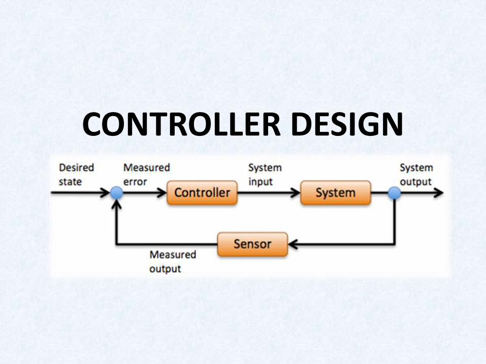
CONTROLLER DESIGN

P PROPORTIONAL CONTROLLER(m)
AIM: set input =1 output= 1.It never happens If it happens plant gets switched off. So always there is a Ess in closed loopProportional controller is used to raise the steady state output.Designed for various values of Ki
Kp %Mp Ϛ Tr
1 6.7 0.65 0.3
0.5 1.14 0.85 0.346
.25 0 >=1 0.521

P controllerKp=1
Kp=0.5
Kp=0.25

OBSERVATIONS(m) As Kp , Ϛ , overshoot ,Tr becomes over damped.Never achieves the steady state.Existence of steady state error.

I INTEGRAL CONTROLLER(m)
Accumulation of past errorsIncreases the order of the system.
Ki Tr %Mp Ts Ϛ
1 0.5 33.2 4.65 0.33
0.5 1.01 12.6 3.41 0.55
0.25 2.11 0.74 3.39 0.91

I controller
Ki=0.25
Ki=0.5
Ki=1

OBSERVATIONS(m)
If Ki Steady state error eliminates. Rise time reduces. Peak over shoot increases. Settling time increases. Damping factor increases Over damped responses
Why not Differential controller???Amplifies High frequency noiseDerivative of sudden changes creates impulsesDerivative action deceases rise time and oscillations

PI Controller(m)
Root locus methodTr<0.3 sec, Ts<0.6sec,%Mp<5%.Kp=2.14, Ki=18.4.Rise time condition satisfied and Ess=0.Settling time and overshoot is heavyKp makes small change in settling time, increase in overshoot.Ki Ts, %Mp.

Step response(m)
Tr=0.10secTs=2.31sec%Mp=66.5Ess=0

Root locus method
Tr<0.3 sec, Ts<0.6sec,%Mp<5%.
Kp=10,Kd=0.858
Ts, %mp reduced drastically
Overshoot error=4%.
PD Controller(m)
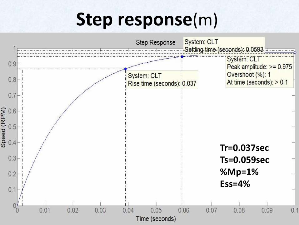
Step response(m)
Tr=0.037secTs=0.059sec%Mp=1%Ess=4%

PID controller(m)
• Root locus
• Combining the requirements. Tr<0.3 sec, Ts<0.6sec,%Mp<5%.
• Kp=6.914 Ki=18.53 Kd=0.3104
• Ts
• Tr
• Ess=0

Step response
Tr=248 msecTs=926 msec%Mp=7.48 %Ess=0

Tr Ts %Mp %Ess
open 0.991sec 1.8003sec 0 8.3
closed 0.215sec 0.652sec 6.77 0.735
P 0.07sec 0.61sec 33.6 6
I 0.59sec 4.65sec 33.2 0
PI 0.1sec 2.31sec 66.5 0
PD 0.037sec 0.059sec 1 4
PID 0.248 sec 0.926 sec 7.48 0
COMPARISON
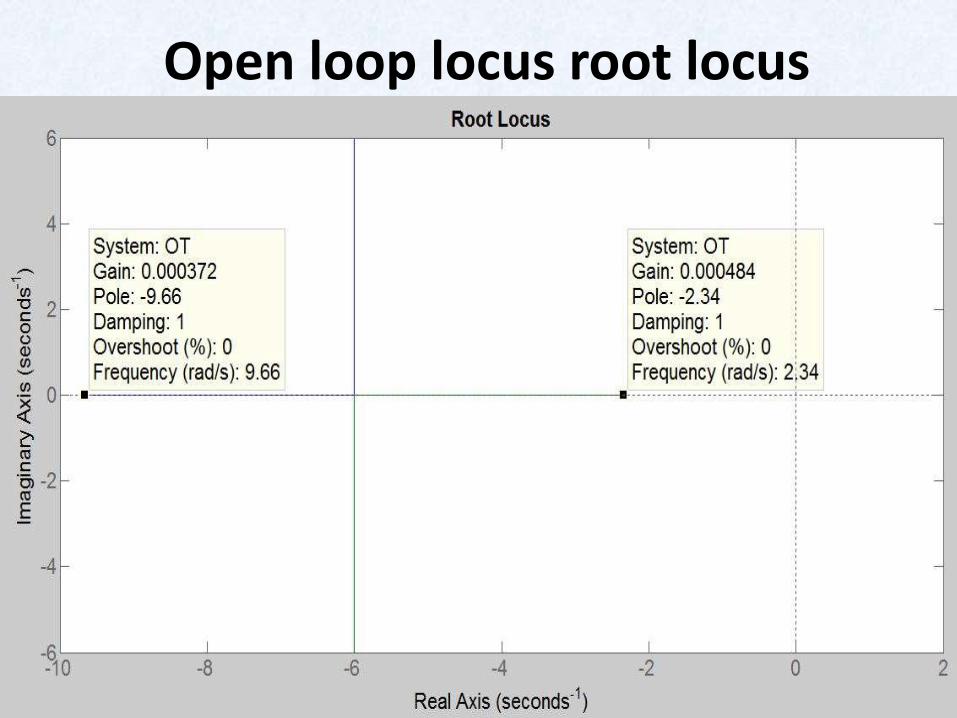
Open loop locus root locus
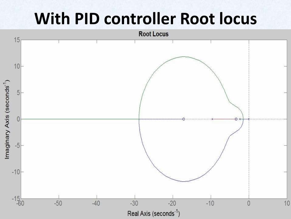
With PID controller Root locus

Gain Margin – Phase MarginGain Margin: additional gain that makes the
system on the verge of instability /gain
perturbation that makesthe system marginally stable.Phase Margin: Additional phase lag that makes the system on the verge of
instability/negative phase perturbation
that makes the system marginally stable.

Why should we consider GM,PM?
• Different rotor Inertia(diff size load) –Gain
• Temperature sensitive(Back emf) Power –Gain
• More drag in Bearings –Gain and Phase
• Slower digital computer(Sensor)-Phase
You cannot know of all these things, So we should define everything in margin.
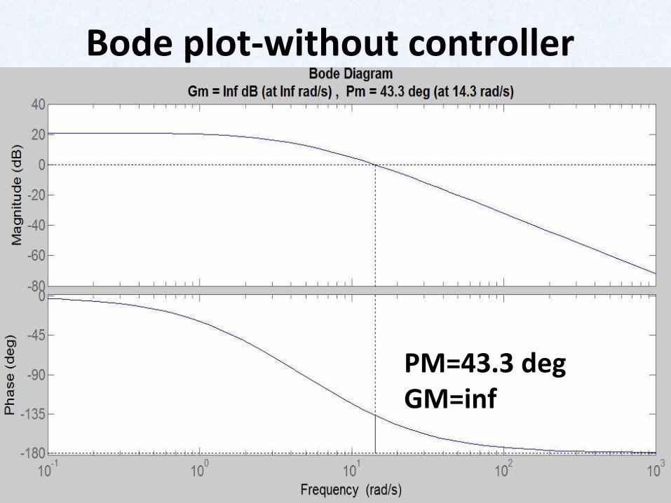
Bode plot-without controller
PM=43.3 degGM=inf

Bode plot-with PID controller
PM=69.3 degGM=inf

Simscape Model DC-Motor