MODEL PREDICTIVE CONTROLLERS FOR A NETWORKED DC SERVO …
55
MODEL PREDICTIVE CONTROLLERS FOR A NETWORKED DC SERVO SYSTEM A THESIS SUBMITTED IN PARTIAL FULFILLMENT OF THE REQUIREMENTS FOR THE DEGREE OF Master of Technology in Control & Automation By RAMESH CHANDRA KHAMARI Roll No -211EE3337 Department of Electrical Engineering National Institute of Technology, Rourkela Rourkela, Orissa 2011-2013
Transcript of MODEL PREDICTIVE CONTROLLERS FOR A NETWORKED DC SERVO …

MODEL PREDICTIVE CONTROLLERS FOR A
NETWORKED DC SERVO SYSTEM
A THESIS SUBMITTED IN PARTIAL FULFILLMENT OF THE
REQUIREMENTS FOR THE DEGREE OF
Master of Technology in Control & Automation
By
RAMESH CHANDRA KHAMARI
Roll No -211EE3337
Department of Electrical Engineering
National Institute of Technology, Rourkela
Rourkela, Orissa
2011-2013

MODEL PREDICTIVE CONTROLLERS FOR A
NETWORKED DC SERVO SYSTEM
A THESIS SUBMITTED IN PARTIAL FULFILLMENT OF THE
REQUIREMENTS FOR THE DEGREE OF
Master of Technology in Control & Automation
By
RAMESH CHANDRA KHAMARI
Under the guidance of
Prof. BIDYADHAR SUBUDHI
Department of Electrical Engineering
National Institute of Technology, Rourkela
Rourkela, Orissa
2011-2013

Department of Electrical Engineering
National Institute of Technology, Rourkela
Odisha, India – 769 008
CERTIFICATE
This is to certify that the thesis titled “Model Predictive Controllers for a Networked DC
Servo System”, submitted to the National Institute of Technology, Rourkela by Ramesh
Chandra Khamari, Roll No. 211EE3337 for the award of Master of Technology in Control &
Automation, is a bona fide record of research work carried out by him under my supervision and
guidance.
The candidate has fulfilled all the prescribed requirements.
The Thesis which is based on candidate’s own work, has not submitted elsewhere for a
degree/diploma.
In my opinion, the thesis is of standard required for the award of a Master of Technology degree
in Control & Automation.
To the best of my knowledge, he bears a good moral character and decent behavior.
Place: Rourkela Prof. Bidyadhar Subudhi Date:

ACKNOWLEDGEMENTS
This project is by far the most significant accomplishment in my life and it would be impossible
without people who supported me and believed in me.
I would like to extend my gratitude and my sincere thanks to my honorable, esteemed supervisor
Dr. Bidyadhar Subudhi, Department of Electrical Engineering. He is not only a great lecturer
with deep vision but also most importantly a kind person. I sincerely thank for his exemplary
guidance and encouragement. His trust and support inspired me in the most important moments
of making right decisions and I am glad to work under his supervision.
I am very much thankful to Prof. Sandip Ghosh for his valuable suggestions and help during the
research period.
I would like to express my sincere gratitude to all the faculty members and staff of the
Department for their unflinching support, inspiration, and cooperation and providing me with all
sort of official facilities in various ways for the completion of the thesis work.
I would also like to thank all my friends, especially, Dinesh, Khushal, Ankush, Pankaj and all
my classmates for extending their technical and personal support and making my stay pleasant
and enjoyable. I am also very much thankful to Mr. Sathyam Bonala, a PhD scholar who
supports me very much.
I would like to thank all those who made my stay in Rourkela an unforgettable and rewarding
experience.
Last but not least I would like to thank my parents, who taught me the value of hard work by
their own example. They rendered me enormous support being apart during the whole tenure of
my stay in NIT Rourkela.
Ramesh Chandra Khamari

i
CONTENTS
Abstract iii
List of Figures iv
List of Tables vi
Acronyms vii
Chapter 1 Introduction
1.1. Introduction 2
1.2. Background 4
1.2.1 Network Control 4
1.2.2 Point-to-Point architecture of a control system 5
1.2.3 Overview of NCS 5
1.3. Literature Review on NCS 6
1.4. Thesis Objectives 8
1.5. Contribution of this thesis 9
1.6. Thesis Organization 9
Chapter 2 Different Issues in NCS
2.1. Introduction 11
2.2. Different delays in Network Control System 11
2.2.1 Effects of delays 14
2.3. Time delay compensation 15
2.4. Different types of time delay control schemes 16
2.4.1 Gain Scheduler Middleware 16
ii
2.4.2 Easy Java Simulations 17
Chapter 3 Model Predictive Control for a Networked DC Servo System
3.1. Introduction 19
3.2. Model predictive control structure 19
3.3. Characteristics of MPC 20
3.4. Advantages of MPC 20
3.5. Application of MPC to networked DC Servo System 21
3.6. DC Motor modeling 22
3.7. Results and Discussion 23
Chapter 4 Design and Analysis of Standard MPC for NCS
4.1. Design of Standard MPC 28
4.2. Simulation Environment 31
4.2.1 TrueTime Simulator 31
4.3. Results and Discussion 33
Chapter 5 Design and Analysis of Robust MPC for NCS
5.1. Introduction 37
5.2. Design of Robust MPC 37
5.3. Results and Discussion 39
Chapter 6 Conclusions and Suggestions for future work
6.1. Conclusions 42
6.2. Suggestions for future work 42
References 45

iii
ABSTRACT
Feedback control systems, wherein the loops used to control the behavior of a plant are
closed through a real time communication network, are called networked control systems.
Networked Control Systems (NCSs) are one type of distributed control systems where
sensors, actuators, and controllers are interconnected by communication networks. The primary
advantages of an NCS are reduced system wiring, ease of system analysis and maintenance.
In this thesis, the analysis and design of networked control systems with the communication
delay and data loss, which are responsible for degradation of the control performance, are
considered. Model predictive control strategies are applied to compensate the communication
delay and data loss in the NCS. Studied about TrueTime Simulator and the control strategies are
applied to a DC servo system using this TrueTime Simulator with communication delay and data
packet loss. Also, the stability and the system performance of the close loop networked control
system are analyzed.

iv
LIST OF FIGURES
Figure No. Page No.
1.1 Typical NCS setup and information flows 3
1.2 Point-to-Point Architecture of a Control System 5
1.3 Block Diagram of a Networked Control System 6
2.1 Block Diagram of Network Control System with Network Delays 11
2.2 Timing diagram of network delay propagation 13
2.3 Closed loop control system with delays 14
2.4 Step response with respect to various where 2ca sc are constant 15
3.1 General Structure of Model Predictive Controller 20
3.2 Angular Velocities with respect to various delays with 24
reference to staircase signal using MPC toolbox
3.3 Angular Velocities with respect to various delays with 24
reference to staircase signal without any controller
3.4 Armature Currents with respect to various delays with 25
reference to staircase signal without any controller
3.5 Armature Currents with respect to various delays with 26
reference to staircase signal using MPC toolbox
4.1 TrueTime Simulink diagram with interfering node 32
4.2 TrueTime Simulink diagram with constant delay 32
4.3 Angular Velocity and Armature Current without interfering node 33

v
4.4 Angular Velocity and Armature Current with 30% of network bandwidth 33
occupied by interfering node
4.5 Angular Velocity and Armature Current with 40% of network bandwidth 34
occupied by interfering node
4.6 Angular Velocity and Armature Current with constant delay =0.0232 34
4.7 Angular Velocity and Armature Current with constant delay =0.0627 35
5.1 TrueTime Simulink diagram 39
5.2 Angular Velocity with reference to staircase signal 40

vi
LIST OF TABLES
Table No. Page No.
1. DC Motor parameter values 23
vii
ACRONYMS
NCS Network Control System
P2P Point-to-Point
ZOH Zero Order Hold
FTC Fault-Tolerant Control
GSM Gain Scheduler Middleware
EJS Easy Java Simulations
MPC Model Predictive Control
DC Direct Current
PI Proportional-Integral
QoP Quality of Performance
GPC Generalized Predictive Control
MAC Media Access Control
CSMA Carrier Sense Multiple Access
CD Collision Detection

CHAPTER 1
INTRODUCTION

Chapter 1 INTRODUCTION
MODEL PREDICTIVE CONTROLLERS FOR A NETWORKED DC SERVO SYSTEM Page 2
1.1 INTRODUCTION
In many control systems such as spacecraft, vehicles and plants mainly in chemical plants,
communication networks are employed to exchange information and control signals between
spatially distributed systems components, like supervisory computers and controllers. In the past
decade, Communication networks have revolutionized the way facilities are controlled, in the
industrial area. It has allowed high data transfer rates for more efficient data storage, trending,
alarming and analysis. The drawbacks that cause continual trouble or distress to the early
generations of networks have been solved, for the most part, making them reliable enough to be
used in the most critical of applications.
Network-based control has emerged as a topic of significant interest in the control
community. It is well known that in many practical systems, the physical plant, sensor,
controller, and actuator are difficult to be located at the same place, so we require to transmit the
signals from one place to another. In modern industrial systems, these components are often
connected over network media (typically digital band-limited serial communication channels),
giving rise to the so-called networked control systems (NCSs). Fig.1.1 [1] shows a typical NCS
setup and its information flows.
The study of NCSs involves both computer networking and control theory. Feedback control
systems, wherein the loops used to control the behavior of a plant are closed through a
real-time communication network. The defining feature of an NCS is that information is
exchanged using a network among control system components.
NCSs are one type of distributed control systems where actuators, sensors and controllers are
interconnected by communication networks. The study of NCSs is an interdisciplinary research
area, combining both network and control theory. The traditional communication architecture
for control systems is point-to-point, that means a wire is connected to the central control
computer with each sensor or actuator point. This change to common-bus introduces
different forms of time delay uncertainty between sensors, actuators, and controllers. Most NCS
research has focused on two areas: communication protocols and controller design.
The issues that needs to be addressed while designing an NCS include, the delays induced by
the network which occurs while exchanging data among devices connected to the shared

Chapter 1 INTRODUCTION
MODEL PREDICTIVE CONTROLLERS FOR A NETWORKED DC SERVO SYSTEM Page 3
medium, and packet losses, because of the unreliable network transmission path, where
packets not only suffer transmission delays but also lost during transmission.
Fig.1.1. Typical NCS setup and information flows
A challenging problem in control of networked-based system is the effects of network delay. The
time require to read a sensor measurement and to send a control signal to an actuator
through the network depends on network characteristics such as their topologies, routing
schemes, etc. The delay problem is severe when data loss occurs during a transmission. The
performance of a networked control system is not only degraded, but also can be destabilized by
the delays.
In this project, controllers have been designed to maintain stability of an NCS in the presence of
network-induced delay (controller-actuator delay and sensor-controller delay). Different
compensation techniques have been proposed to minimize delay’s effect.

Chapter 1 INTRODUCTION
MODEL PREDICTIVE CONTROLLERS FOR A NETWORKED DC SERVO SYSTEM Page 4
1.2 BACKGROUND
In NCS background there are network and controller are present. There are several techniques
used to transmit information through the network. Nearly all data network systems in use today
use binary digits (bits), a series of 1s and 0s, to send information. Messages are assembled into
packets with formatting and addressing information, along with the data. The general form of a
message packet or frame is a leading header (sometimes called the preamble), the data area
(called the payload), and the trailer. The header contains addressing and error checking
information, the data area contains the actual data being transmitted, and the trailer contains
more error checking and message management information (e.g. parity and stop bits). Parity is a
simple error checking method which uses the number of 1s in a byte (even or odd) to determine
if the byte was received correctly.
Simplex system provides communication in one direction, all of the time. Half-duplex is
bidirectional communication allowed in one direction at any given time, and full duplex is
bidirectional transmission in both directions simultaneously. In addition to this, synchronous
(clocked) transmissions are timed so that both devices know exactly when a transmission will
begin and end, whereas asynchronous (un-clocked) transmissions must mark the beginning and
end of messages. Synchronous transmission is usually faster than asynchronous, but the timing
issue between two remote machines can introduce problems causing asynchronous transmission
to be simpler and less expensive, and therefore more widely used. Asynchronous transmission
does, however, introduce extra control bits into a message, which slows actual data rate.
1.2.1 Network control
Networked control system is combination of two engineering fields, computer network and
control. We use wired or wireless computer networks. Because NCSs are implemented over a
network, a good underlying communication network protocols, such as Token Bus or Token
Ring, Ethernet is required to analyze and model the system’s characteristic. A Networked
Control System (NCS) is a control system wherein the control loops are closed through a real-
time network. The feature of an NCS is that control and feedback signals are exchanged among
the system's components in the form of information packages through a network.

Chapter 1 INTRODUCTION
MODEL PREDICTIVE CONTROLLERS FOR A NETWORKED DC SERVO SYSTEM Page 5
1.2.2 Point-to-Point Architecture of a Control System
Fig.1.2 shows a control system implemented as a point-to-point (P2P) network. It needs huge
wiring connected from sensors to computer and computer to actuators and more over becomes
complicated on requirement of setting the physical setup and functionality.
Fig.1.2. Point-to-Point Architecture of a Control System
To remove the above problems posed by centralized control, Networked Control System (NCS)
has received considerable attention with advances in control and communication technologies.
1.2.3 Overview of NCS
A networked control system (NCS) is a feedback control system where information from the
sensors and the controllers is sent over an electronic communication network [11, 10, 12]. NCSs
offer reduced cost and relatively simple implementation, as well as greatly increased flexibility.
Network protocols have been designed specifically for use in control systems, but other, more
general network protocols are also widely used [15]. Fig.1.3 shows the block diagram of a
typical networked control system.

Chapter 1 INTRODUCTION
MODEL PREDICTIVE CONTROLLERS FOR A NETWORKED DC SERVO SYSTEM Page 6
Fig.1.3. Block Diagram of a Networked Control System
NCSs are not without their drawbacks. At best, communication networks can introduce delays,
but the network can also introduce time-varying random delays and data packet loss.
1.3 LITERATURE REVIEW ON NCS
Networked control systems are control systems comprised of the system to be controlled and of
actuators, sensors, and controllers, the operation of which is coordinated via a
communication network. These systems are typically spatially distributed, and may operate in an
asynchronous manner, but operate by coordinating each other to achieve desired overall
objectives. Control systems with spatially distributed components have existed for several
decades. Examples include control systems in chemical process plants, refineries, power
plants, and airplanes. In the past, in such systems the components were connected via
hardwired connections and the systems were designed to bring all the information from
the sensors to a central location where the conditions were being monitored and decisions were
made on how to control the system.
The control policies then were implemented via the actuators, which could be valves, motors,
etc. What is different today is that technology can put low-cost processing power at
remote locations via microprocessors and that information can be transmitted reliably via
shared digital networks or even wireless connections. These technology driven changes are

Chapter 1 INTRODUCTION
MODEL PREDICTIVE CONTROLLERS FOR A NETWORKED DC SERVO SYSTEM Page 7
fueled by the high costs of wiring and the difficulty in introducing additional components
into the systems as the needs change.
Traditional control systems composed of interconnected controllers, sensors, and actuators have
been successfully implemented using a point-to-point architecture. As an alternative to point-to-
point, the common-bus network architecture offers more efficient re-configurability, better
resource utilization, and also reduces installation and maintenance cost, which is called
networked control systems.
In a NCS, various delays with variable length occur due to sharing a common network
medium, which are called network-induced delays. The network-induced delay in NCSs occurs
when actuators, sensors and controllers exchange data across the network. Generally, the
controlled plant in NCS is assumed to be continuous-time, and thus the actuator implements
zero-order hold (ZOH) holding the last control until the next one arrives or until the next
sample time. Since networks are used for transmitting the measurements from the plant
output to the controller, the plant has to be sampled, which motivates the use of discrete-
time controllers. Zhang et al. [7] investigated the problems of stability and stabilization of a class
of multi-mode linear discrete time systems.
Today, NCSs are moving into distributed NCSs [8], which are multidisciplinary efforts whose
aim is to produce a network structure and components that are capable of integrating distributed
sensors, distributed actuators, and distributed control algorithms over a communication network
in a manner that is suitable for real-time applications. The controller may be physically placed in
a different location from the plant, actuators and sensors, resulting in a distributed control
system. The controller can be time driven or event driven, so it can calculate the new control
signal at discrete time instants with a constant sample time or it can calculate the control
signal immediately once it gets a new measurement from the sensor. In addition, the actuator
can be time or event-driven.
The consumer markets have already changed by the networks, mainly the wireless ones. Hand-
held computers with wireless links through which the computers can communicate, and
sensors, such as cameras, are all around us. In the industries, the use of wireless technology is at

Chapter 1 INTRODUCTION
MODEL PREDICTIVE CONTROLLERS FOR A NETWORKED DC SERVO SYSTEM Page 8
a very early stage, although it would bring obvious benefits, as wireless networking extends the
possibilities of NCS.
With increasing real-life applications for NCS, the real-time secured control is an important
issue. This gives rise to a real-time optimization problem and security threat modeling
requirement in NCS. Designing a fault-tolerant control (FTC) system for a large-scale complex
NCS is still very difficult due to the large number of sensors and actuators spatially distributed
on a network. Modifying the control part of the system depending upon the network delay
behavior is one way of dealing with the problem. On the other hand, researchers in the field of
wireless networking and communication are working to build new protocols which will give the
flexibility to the system and make it time independent [9].
A gain scheduler middleware (GSM) is developed by Tipsuwan and Chow to alleviate the
network time delay effect on the NCS.
The new information technologies provide great opportunities in control education. The use of
remote control labs to teach the behavior of control systems through a network is an application
of this. In 2010, a new approach to create interactive networked control labs is described [3].
Two main software tools are used; those are MATLAB and Easy Java Simulations (EJS).
1.4 THESIS OBJECTIVES
Various control techniques have been developed for network control system but a
technique to actively compensation of the random network delay is not available. Our
objective is to apply Model Predictive Control (MPC) schemes to compensate the network delay
in network control systems. In this thesis, different MPC techniques are to design and these
techniques are applied to a networked control direct current (DC) motor and to simulate with
TrueTime simulator to illustrate the effectiveness and robustness of the proposed delay modeling
and control strategies.

Chapter 1 INTRODUCTION
MODEL PREDICTIVE CONTROLLERS FOR A NETWORKED DC SERVO SYSTEM Page 9
1.5 CONTRIBUTION OF THIS THESIS
The major contributions of this thesis are
Review of the Networked Control System (NCS).
Study of TrueTime Simulator and its application.
Application of Model Predictive Controller (MPC) toolbox to a networked DC Motor.
Design and application of Standard MPC for the networked DC Motor in TrueTime
Simulator.
Design and application of Robust MPC for the networked DC Motor in TrueTime
Simulator.
Analyzing the effectiveness of the designed MPCs in avoiding instability arising out of
delays in the networked control plant (DC Motor).
1.6 THESIS ORGANIZATION
In Chapter 2, details regarding delays in NCS and different time delay compensation or
control schemes are discussed.
In Chapter 3, details about Model Predictive Control (MPC), DC Motor Modeling, MPC
toolbox and application of MPC toolbox to DC Motor is discussed.
In Chapter 4, studied about TrueTime Simulator, analysis and design of Standard MPC
and implementation of this MPC in TrueTime Simulator.
In Chapter 5, design and analysis of Robust MPC and implementation in TrueTime
Simulator is discussed.
In Chapter 6, the thesis is concluded and scope for future work is discussed.

CHAPTER 2
DIFFERENT ISSUES IN NCS

Chapter 2 DIFFERENT ISSUES IN NCS
MODEL PREDICTIVE CONTROLLERS FOR A NETWORKED DC SERVO SYSTEM Page 11
2.1 INTRODUCTION
In networked control system, there are mainly two problems. First one is the networked induced
delays which are induced in the system due to communication channel. Second one is the data
packet dropouts due to the node failure and data collision. This chapter contains detail about
main issues in the networked control system. In a networked control system the main issue is
delay. The effect of this delay is instability and system performance degradation of NCS. In this
section many compensation techniques by which delay will compensate are also given.
2.2 DIFFERENT DELAYS IN NETWORK CONTROL SYSTEM
Since an NCS operates over a network, data transfers between the controller and the remote
system will induce network delays in addition to the controller processing delay. Fig. 2 shows
network delays in the control loop, where r, u and y are reference signal, control signal and
output signal respectively, T is sampling period, and k is time index. Most of networked control
methodologies use the discrete-time formulation shown in Fig.2.1 [4].
Fig.2.1. Block Diagram of Network Control System with Network Delays
Network delays[4] in an NCS can be categorized from the direction of data transfers as
the sensor-to-controller delay sc and the controller-to-actuator delay ca . The delays are
computed as sc t tcs sc , tca rs cet where t sc is the time instant that the remote system
encapsulates the measurement to a frame or a packet to be sent, cst is the time instant that
the controller starts processing the measurement in the delivered frame or packet, cet is the

Chapter 2 DIFFERENT ISSUES IN NCS
MODEL PREDICTIVE CONTROLLERS FOR A NETWORKED DC SERVO SYSTEM Page 12
time instant that the main controller encapsulates the control signal to a packet to be sent,
and rst is the time instant that the remote system starts processing the control signal. In fact,
both network delays can be longer or shorter than the sampling time T. The controller processing
delay c and both network delays can be lumped together as the control delay t for ease of
analysis. This approach has been used in some networked control methodologies. Although the
controller processing delay c always exists, it could be neglected as it is small compared to the
network delays.
Waiting delay ( w ): The waiting time delay is the delay, of which a source (the main controller
or the remote system) has to wait for queuing and network availability before actually
sending a frame or a packet out.
Frame time delay ( f ): The frame time delay is the delay during the moment that the source is
placing a frame or a packet on the network.
Propagation delay ( p ): The propagation delay is the delay for a frame or a packet traveling
through a physical media.
Generally, the controlled plant in NCS is assumed to be continuous-time, and thus the
actuator implements zero-order hold (ZOH) holding the last control until the next one arrives or
until the next sample time. Since networks are used for transmitting the measurements
from the plant output to the controller, the plant has to be sampled (sample time T),
which motivates the use of discrete-time controllers.

Chapter 2 DIFFERENT ISSUES IN NCS
MODEL PREDICTIVE CONTROLLERS FOR A NETWORKED DC SERVO SYSTEM Page 13
Fig.2.2. Timing diagram of network delay propagation
Output signal Actual output
Signal
Delayed output
Signal (sc )
y(k) y(kT-
sc )
Time
Time
Control signal
Control signal with
respect to y(k)
u(k)
Delayed control
Signal (by sc )
u(kT- sc )
cst set
cet rst
sc
c
ca
T
w f
p
kT (k+1)T

Chapter 2 DIFFERENT ISSUES IN NCS
MODEL PREDICTIVE CONTROLLERS FOR A NETWORKED DC SERVO SYSTEM Page 14
2.2.1 EFFECTS OF DELAYS
The main problem occurred due to the delays in control loop are widely known to degrade
system performance and destabilize of a control system by reducing the system stability margin.
The closed loop proportional-integral (PI) control system with delays in Fig.2.4 is used to briefly
illustrate system performance degradation by delays in the loop, where R(s),Y(s),U(s) and E(s)
are the reference signal, output signal, control input and error signal in Laplace domain [4].
Where, ( ) ( ) ( )E s R s Y s (1.1)
The transfer function of the controller and the plant are described as given below:
( ( ))
( )
IP
Pc
Ks
KG s
s
0.1701, 0.378P IK K (1.2)
2029.826( )
( 26.29)( 2.296)PG s
s s
Where ( )cG s is a PI Controller, is the parameter to adjust PK and IK , IK is the integral gain,
PK is the proportional gain and ( )PG s is the plant of DC Motor [16].
Fig.2.3. Closed loop control system with delays
Solving the above closed loop system with =1 and with various where 2ca sc
are constant. As shown in Fig.2.4, system performance degrades with higher overshoot and

Chapter 2 DIFFERENT ISSUES IN NCS
MODEL PREDICTIVE CONTROLLERS FOR A NETWORKED DC SERVO SYSTEM Page 15
longer settling time when the delays 2ca sc are longer and system becomes unstable
with increasing delays.
Fig.2.4. Step response with respect to various where 2ca sc
are constant.
There have been many studies to derive stability criteria for an NCS in order to guarantee that
the NCS can remain stable in certain contain.
2.3 TIME DELAY COMPENSATION
The time delays in the NCS may deteriorate the system performance and cause the
system instability. Therefore, it is necessary to design a controller which can compensate for the
time delays and improve the control performance of the NCS.
Different mathematical, heuristic and statistical-based approaches are taken for delay
compensation in NCSs. Several advanced techniques have been presented in literature [6] that
compensate network delays and potentially enough to be used in critical real-time applications.
The sensor to controller delay can be known when the sensors data is used by the controller to
generate a control signal. In case of controller-actuator delay, the controller does not know how
long it will take the control signal to reach actuator. So no exact correction can be made at the
time of control calculation.
0 0.2 0.4 0.6 0.8 1 1.2 1.4 1.6 1.8 20
0.2
0.4
0.6
0.8
1
1.2
1.4
1.6
1.8
2
Time(s)
Y
t=0.0005
t=0.0232
t=0.0627
t=0.3150

Chapter 2 DIFFERENT ISSUES IN NCS
MODEL PREDICTIVE CONTROLLERS FOR A NETWORKED DC SERVO SYSTEM Page 16
An estimator can be used to predict an un-delayed plant state and make it available for control
calculation. The estimator must estimate all state of the plant using partial state measurements
and also compensate for sensor delay. This can be implemented by either full state feedback or
output feedback.
In the NCS environment the main goal of the control system is to maintain Quality of
Performance (QoP) of the control system regardless of the delays in the network. The system
should be robust and be able to compensate the delay induced by the network.
2.4 DIFFERENT TYPES OF TIME DELAY CONTROL SCHEMES
The time delay compensation techniques are used to compensate the time delays causes in the
feedback loop. Different types of time delay compensation schemes are given below.
1. Model Predictive Controller
2. Smith predictor
3. PID controller
4. Optimal controller
5. Fuzzy controller
6. Robust control
7. Sliding mode controller
8. Adaptive controller
In addition to the above methods there are different network control approaches, different
software, different platforms and systems are used to control the NCS. These are given below.
2.4.1 Gain Scheduler Middleware: A gain scheduler middleware (GSM) is developed by
Tipsuwan and Chow to alleviate the network time delay effect on the NCS. Conventionally, in
order to control an application over a data network, a specific networked control or tele-
operation algorithm to compensate network delay effects is usually required for controller
design. So the existing controller has to be redesigned or replaced by a new controller system.
The replacement process is generally costly, inconvenient, and time consuming. Gain Scheduler
Middleware [2] is a novel methodology to enable existing controllers for networked control and
tele-operation. The proposed methodology uses middleware to modify the output of an existing

Chapter 2 DIFFERENT ISSUES IN NCS
MODEL PREDICTIVE CONTROLLERS FOR A NETWORKED DC SERVO SYSTEM Page 17
controller based on a gain scheduling algorithm with respect to the current network traffic
conditions. This approach can save much time and investment cost by utilizing existing
controller.
2.4.2 Easy Java Simulations: In 2010, a new approach to create interactive networked control
labs [3] is described. This is described by two main software tools that are MATLAB and Easy
Java Simulations. MATLAB is a widely used tool in the control community, whereas Easy Java
Simulations is a powerful tool, which is used to build interactive applications in Java without
special programming skills. The remote labs created by this approach give to students the
opportunity to face the effects of network delays on the controlled system and also to specify on
the fly their own control algorithm.
EJS is a platform to control NCS with externally connecting MATLAB/Simulink. EJS is a free
software tool for rapid creation of applications in Java with high-level graphical capabilities and
with an increased degree of interactivity. The applications created by EJS can be standalone Java
applications or applets. The source files of the EJS applications are saved in a customized xml
format. EJS is different from most other authoring tools in that EJS is not designed to make life
easier for professional programmers but has been conceived for science students and teachers.
EJS structures the application in two main parts, the model and the view. The model can be
described by means of pages of Java code and ordinary differential equations or by connecting to
external applications (such as MATLAB). The view provides the visualization of the application
and also the user interface elements required for user interaction. These view elements can be
chosen from a set of predefined components to build a treelike structure. Model and view can be
easily interconnected so that any change in the model state is automatically reflected by the view,
and vice versa.

CHAPTER 3
MODEL PREDICTIVE CONTROL
FOR A NETWORKED DC SERVO
SYSTEM

Chapter 3 MODEL PREDICTIVE CONTROL FOR A NETWORKED DC SERVO SYSTEM
MODEL PREDICTIVE CONTROLLERS FOR A NETWORKED DC SERVO SYSTEM Page 19
3.1 INTRODUCTION
Model Predictive Control (MPC) is a type of control in which the current control signal is
determined such that a desirable output behavior results in the future. Thus we need the ability to
efficiently predict the future output behavior of the system. This future behavior is a function of
past inputs to the process as well as the inputs that we are considering to take in the future.
All MPC systems are based on the idea of generating values for process model and other
measurements. In MPC structure there is a feedback or feed forward path to compute the
process measurements.
There are different forms of MPC are available to make model predictive controller:
GPC(Generalized Predictive Control)
Standard MPC
Modified MPC
Robust MPC
3.2 MODEL PREDICTIVE CONTROL STRUCTURE
There are mainly three components are available in MPC structure
1. The process model
2. The cost function
3. The optimizer
The information about the controlled process and prediction of the response of the process values
according to the manipulated control variables are done by the process model. Then the error is
reduced by the minimization of the cost function.
In the last step various types of optimization techniques are used and the output gives to the input
sequence for the next prediction horizon. The general structure of Model Predictive Controller is
shown in Fig.3.1.

Chapter 3 MODEL PREDICTIVE CONTROL FOR A NETWORKED DC SERVO SYSTEM
MODEL PREDICTIVE CONTROLLERS FOR A NETWORKED DC SERVO SYSTEM Page 20
Fig.3.1. General Structure of Model Predictive Controller
3.3 CHARACTERISTICS OF MPC
The main features/characteristics of MPC are [17]
Moving horizon technique implementation with Control horizon, Prediction horizon and
Receding horizon control concepts.
Performance based time domain formulation.
An explicit system model is used for prediction of future plant dynamics.
Constraints values can be taken in to consideration.
3.4 ADVANTAGES OF MPC
There are many advantages of MPC are available, due to which we prefer MPC as a controller in
many applications.
Structural changes are available in this method
In this, we can predict how far we wish the future to be predicted for.
Also the number of parameters used to capture the future control trajectory can be
predicted.

Chapter 3 MODEL PREDICTIVE CONTROL FOR A NETWORKED DC SERVO SYSTEM
MODEL PREDICTIVE CONTROLLERS FOR A NETWORKED DC SERVO SYSTEM Page 21
In this tuning method is easy
We can handle unstable system and non-minimal phase by this method.
3.5 APPLICATION OF MPC TO NETWORKED DC MOTOR
There are various applications of MPC such as in spacecraft, vehicles, plant mainly in chemical
plant and in servo mechanism. In this, MPC is applied to networked DC Servo system.
MPC toolbox: Model Predictive Control Toolbox provides functions, an application, and
Simulink blocks for systematically analyzing, designing, and tuning model predictive controllers.
We can set and modify the predictive model, prediction horizons, control, input and output
constraints as well as weights. The toolbox enables us to diagnose issues that could lead to run-
time failures and provides advice on changing weights and constraints to improve performance
and robustness.
The MPC control strategy was simulated using MPC toolbox which is a MATLAB-based
toolbox. The Cost function is given as
Where
= number of controller sampling intervals in the scenario
= number of controlled outputs
= number of manipulated variables
= set point (or reference) tracking error i.e. the difference between output j and its set point
at time step i
= deviation of manipulated variable j from its target value at time step i
= change in manipulated variable j at time step i
= performance weight for output j
= performance weight for manipulated variable j
= performance weight for change in manipulated variable j
yn
un
yije
uije
y
jw
u
jw
2 2 2
1 1 1
( ) ( )( )y u
n nN
i j j
y u uJj uij j ijj yij w e w uw e
iju
u
jw
N

Chapter 3 MODEL PREDICTIVE CONTROL FOR A NETWORKED DC SERVO SYSTEM
MODEL PREDICTIVE CONTROLLERS FOR A NETWORKED DC SERVO SYSTEM Page 22
3.6 DC MOTOR MODELLING
The equation for the electrical circuit of the DC motor is
aa a b
die L Ri K
dt (2.1)
and the mechanical torque is
l a
dJ B T Ki
dt
(2.2)
where ae is the armature input voltage, L is the armature inductance, ai is the armature current,
R is the armature resistance, J is the system moment of inertia, B is the system damping
coefficient, K and bK are the torque constant and the back emf constant, respectively, lT is the
load torque and ω is the angular velocity of the rotor. The DC motor has a driven load that can be
a robot arm or an unmanned electric vehicle. Using u = ae as the control signal for the DC motor
and introducing two state variables, the armature current and the angular velocity of the rotor,
that is
1 ax i (2.3a)
2x (2.3b)
The dynamics of the DC motor can be described by the following continuous-time state space
description
( ) ( ) ( )c cx t A x t b u t (2.4a)
( ) ( )cy t C x t (2.4b)
Where 1 2( ) ( )Tx t x x is the system state, ( )u t is the system input, 2( )y t is the system
output,
b
c
KR
L LA
K B
J J
,
1
0cb L
and 1 0
0 1cC
are the system matrices.

Chapter 3 MODEL PREDICTIVE CONTROL FOR A NETWORKED DC SERVO SYSTEM
MODEL PREDICTIVE CONTROLLERS FOR A NETWORKED DC SERVO SYSTEM Page 23
3.7 RESULTS AND DISCUSSION
The DC motor control system was simulated using Model Predictive Control (MPC), a simulator
developed in MATLAB where the values of the parameters used in simulations are given in
Table 1. Here DC motor control system was simulated using MPC with considering network
delay effects.
Table.1. DC Motor parameter values
Symbol Value Measure unit Description
J 642.6
2kgm inertia
L 3170 H inductance
R 4.67 Ω terminal resistance
B 647.3 N m s/rad damping coefficient
K
314.7 N m/A torque constant
314.7 V s/rad back-EMF constant
lT 0 N m load torque
min
ae −15 V minimum armature voltage
max
ae 15 V maximum armature voltage
min
ai −5 A minimum armature current
max
ai 5 A maximum armature current
min
-400 rad/s minimum angular velocity
max
400 rad/s maximum angular velocity
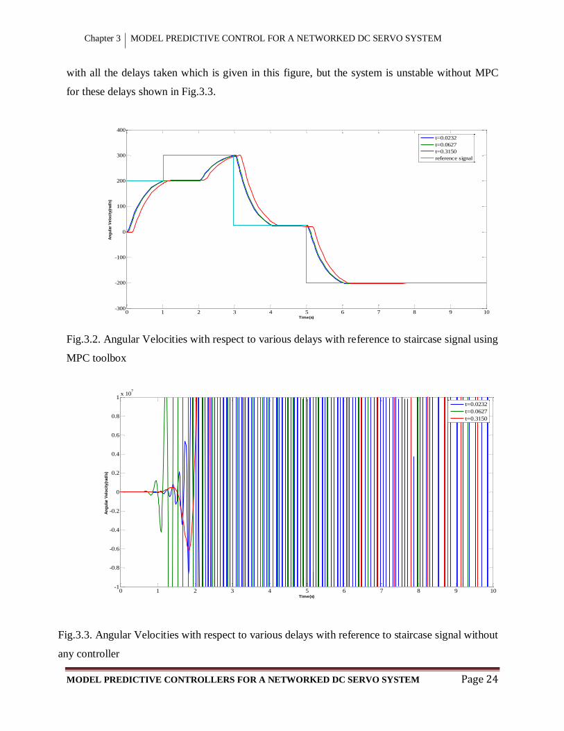
With the application of MPC toolbox to the DC Motor, the Fig.3.2 shows the Angular Velocities
with respect to various delays where 2ca sc are constant. The reference taken is
staircase signal. In this figure, it is shown that with MPC, the reference is reached in a short time
and with very less overshoot for the first delay. For the second and third delay, performance
degrades with increasing settling time with increasing delays but the system is stable using MPC
bK
Chapter 3 MODEL PREDICTIVE CONTROL FOR A NETWORKED DC SERVO SYSTEM
MODEL PREDICTIVE CONTROLLERS FOR A NETWORKED DC SERVO SYSTEM Page 24
with all the delays taken which is given in this figure, but the system is unstable without MPC
for these delays shown in Fig.3.3.
Fig.3.2. Angular Velocities with respect to various delays with reference to staircase signal using
MPC toolbox
Fig.3.3. Angular Velocities with respect to various delays with reference to staircase signal without
any controller
0 1 2 3 4 5 6 7 8 9 10-300
-200
-100
0
100
200
300
400
Time(s)
An
gu
lar
Velo
cit
y(r
ad
/s)
t=0.0232
t=0.0627
t=0.3150
reference signal
0 1 2 3 4 5 6 7 8 9 10-1
-0.8
-0.6
-0.4
-0.2
0
0.2
0.4
0.6
0.8
1x 10
7
Time(s)
An
gu
lar
Velo
cit
y(r
ad
/s)
t=0.0232
t=0.0627
t=0.3150

Chapter 3 MODEL PREDICTIVE CONTROL FOR A NETWORKED DC SERVO SYSTEM
MODEL PREDICTIVE CONTROLLERS FOR A NETWORKED DC SERVO SYSTEM Page 25
The result shown in Fig.3.4 shows the Armature Currents of DC Motor with respect to different
delays without any controller with reference to staircase signal. In this figure, it is shown
degradations of performance and overshoot of system is increasing with increasing delays.
Fig.3.4. Armature Currents with respect to various delays with reference to staircase signal
without any controller
After applying MPC controller to this, the figure shown in 3.5 shows that Armature Currents
reached the reference in a short time with less overshoot compared to without MPC and in above
both cases, the time delay is compensated with better performance with MPC.
0 1 2 3 4 5 6 7 8 9 10-50
-40
-30
-20
-10
0
10
20
30
40
50
Time(s)
Arm
atu
re C
urr
ent(
A)
t=0.0232
t=0.0627
t=0.3150

Chapter 3 MODEL PREDICTIVE CONTROL FOR A NETWORKED DC SERVO SYSTEM
MODEL PREDICTIVE CONTROLLERS FOR A NETWORKED DC SERVO SYSTEM Page 26
Fig.3.5. Armature Currents with respect to various delays with reference to staircase signal using
MPC toolbox
In above Fig.3.2 to Fig.3.5, the results shown is taken with respect to various delays where
2ca sc are constant.
0 1 2 3 4 5 6 7 8 9 10-3
-2
-1
0
1
2
3
Time(s)
Arm
atu
re C
urr
en
t(A
)
t=0.0232
t=0.0627
t=0.3150

CHAPTER 4
DESIGN AND ANALYSIS OF
STANDARD MPC FOR NCS

Chapter 4 DESIGN AND ANALYSIS OF STANDARD MPC FOR NCS
MODEL PREDICTIVE CONTROLLERS FOR A NETWORKED DC SERVO SYSTEM Page 28
4.1 DESIGN OF STANDARD MPC
After conversion of Continuous model given in equation (2.4) to Discrete model
( 1) ( ) ( )m m m mx k A x k B u k (3.1)
( ) ( )m my k C x k
(3.2)
( 1) ( ) ( ( ) ( 1)) ( ( ) ( 1))m m m m m mx k x k A x k x k B u k u k
( 1) ( ) ( )m m m mx k A x k B u k (3.3)
Where
( 1) ( 1) ( )m m mx k x k x k
( ) ( ) ( 1)m m mx k x k x k
( ) ( ) ( 1)u k u k u k
( ) ( ) ( )T
Tx k
mx k y k (3.4)
Also
( 1) ( ) ( ( 1) ( )) ( 1)m m m m my k y k C x k x k C x k
( ) ( )m m m m mC x k C u k
(3.5)
From (3.3) and (3.5),
( 1) ( )( )
( 1) ( )1
T
mm mm
m mm m
Bx k x kAm u k
C By k y kC A
O
(3.6a)
( )
( ) 1( )m
m
ky k O
y k
x
(3.6b)

Chapter 4 DESIGN AND ANALYSIS OF STANDARD MPC FOR NCS
MODEL PREDICTIVE CONTROLLERS FOR A NETWORKED DC SERVO SYSTEM Page 29
Where 0 0 0mO
Equation (3.6) is called augmented model.
The augmented model is calculated from the discrete model.
Assuming that at the sampling instant ik ,
ik > 0, the state variable vector ( )ix k is available
through measurement, the state ( )ix k provides the current plant information. The future control
trajectory is denoted by
, ( 1)..., ( 1)i i i cuk u k u k N
Where cN is called the control horizon.
Let us define
[ ( ), ( 2 ),... ( )]T
Yi i i i i P iy k k y k k y k N k
(3.7)
[ ( ), ( 1),... ( 1)]T
Ui i i cu k u k u k N
(3.8)
Where in the single-input and single-output case, the dimension of Y is pN and the dimension of
ΔU is cN .
We can write compact matrix form as
( )iY Fx k U (3.9)
Where,

Chapter 4 DESIGN AND ANALYSIS OF STANDARD MPC FOR NCS
MODEL PREDICTIVE CONTROLLERS FOR A NETWORKED DC SERVO SYSTEM Page 30
2
23
1 2
0 0 . . . 0
0 . . . 0
. . . 0
. ., ..
. ..
. ..
. . .p p p cpN N N NN
CA CB
CAB CBCA
CA B CAB CBCA
F
CA B CA B CA BCA
Assuming that the data vector that contains the set-point information is
1 1 . . . 1 ( )Ts iR r k
The cost function is defined as
( ) ( )T Ts sJ R Y R Y U R U
(3.10)
Where ( ) ( )Ts sR Y R Y is objective of minimizing the errors and TU R U is consideration
given to the size U .
R
= diagonal matrix c cw N Nr I
wr Tuning parameter.
To find the optimal ΔU that will minimize J, by using (3.9),
2 ( ( )) 2( ) 0T Ts i
JR Fx k R U
U
from which we find the optimal solution for the control signal as
1( ) ( ( ))T Ts iU R R Fx k
(3.11)
And
1
[10...0]p
T Ty N sK R R
(3.12)
Chapter 4 DESIGN AND ANALYSIS OF STANDARD MPC FOR NCS
MODEL PREDICTIVE CONTROLLERS FOR A NETWORKED DC SERVO SYSTEM Page 31
1[10...0] ( ) ( )p
T Tmpc NK R F
(3.13)
mpc x yK K K (3.14)
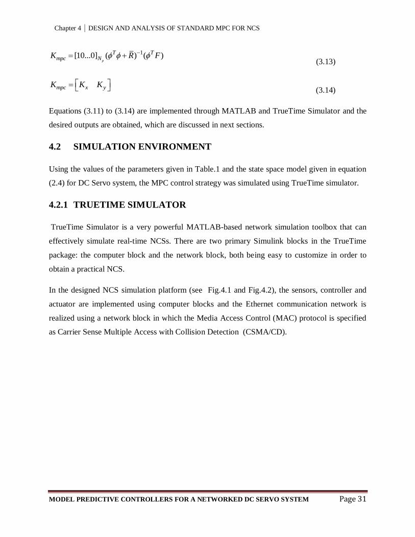
Equations (3.11) to (3.14) are implemented through MATLAB and TrueTime Simulator and the
desired outputs are obtained, which are discussed in next sections.
4.2 SIMULATION ENVIRONMENT
Using the values of the parameters given in Table.1 and the state space model given in equation
(2.4) for DC Servo system, the MPC control strategy was simulated using TrueTime simulator.
4.2.1 TRUETIME SIMULATOR
TrueTime Simulator is a very powerful MATLAB-based network simulation toolbox that can
effectively simulate real-time NCSs. There are two primary Simulink blocks in the TrueTime
package: the computer block and the network block, both being easy to customize in order to
obtain a practical NCS.
In the designed NCS simulation platform (see Fig.4.1 and Fig.4.2), the sensors, controller and
actuator are implemented using computer blocks and the Ethernet communication network is
realized using a network block in which the Media Access Control (MAC) protocol is specified
as Carrier Sense Multiple Access with Collision Detection (CSMA/CD).
Chapter 4 DESIGN AND ANALYSIS OF STANDARD MPC FOR NCS
MODEL PREDICTIVE CONTROLLERS FOR A NETWORKED DC SERVO SYSTEM Page 32
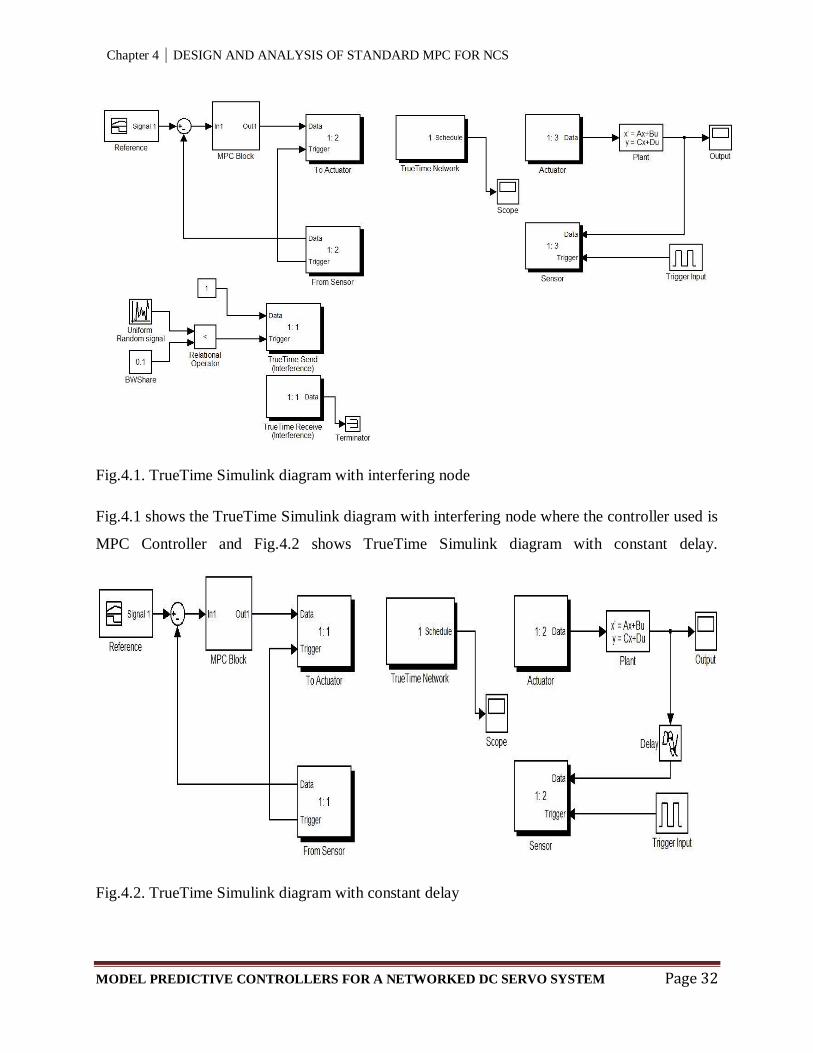
Fig.4.1. TrueTime Simulink diagram with interfering node
Fig.4.1 shows the TrueTime Simulink diagram with interfering node where the controller used is
MPC Controller and Fig.4.2 shows TrueTime Simulink diagram with constant delay.
Fig.4.2. TrueTime Simulink diagram with constant delay

Chapter 4 DESIGN AND ANALYSIS OF STANDARD MPC FOR NCS
MODEL PREDICTIVE CONTROLLERS FOR A NETWORKED DC SERVO SYSTEM Page 33
4.3 RESULTS AND DISCUSSION
Fig.4.3 shows the output of Angular Velocity and Armature Current without any interfering node
Fig.4.3. Angular Velocity and Armature Current without interfering node
and Fig.4.4 shows the output with the percentage of the network bandwidth occupied by the
interfering node was set to 30% and also the simulation was done by taking bandwidth 10% and
20%.It is observed that the outputs are very less effected up to 39% of network bandwidth
occupied by interfering node. But when the bandwidth occupied is increased to 40% (shown in
Fig.4.5) and more the system outputs become unstable.
Fig.4.4. Angular Velocity and Armature Current with 30% of network bandwidth occupied by
interfering node
0 1 2 3 4 5 6 7 8 9 10-300
-200
-100
0
100
200
300
400
Time(s)
Ang
ular
Vel
ocity
(rad
/s) a
nd A
rmat
ure
Cur
rent
(A)
Armature Current
Angular Velocity
Reference Input
0 1 2 3 4 5 6 7 8 9 10-300
-200
-100
0
100
200
300
400
Time(s)
Ang
ular
Vel
ocity
(rad
/s) a
nd A
rmat
ure
Cur
rent
(A)
Armature Current
Angular Velocity
Reference Input
Chapter 4 DESIGN AND ANALYSIS OF STANDARD MPC FOR NCS
MODEL PREDICTIVE CONTROLLERS FOR A NETWORKED DC SERVO SYSTEM Page 34
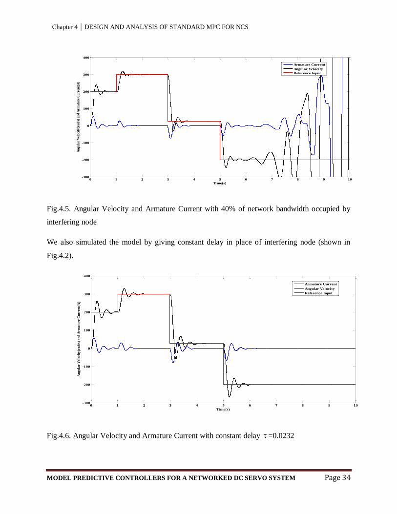
Fig.4.5. Angular Velocity and Armature Current with 40% of network bandwidth occupied by
interfering node
We also simulated the model by giving constant delay in place of interfering node (shown in
Fig.4.2).
Fig.4.6. Angular Velocity and Armature Current with constant delay =0.0232
0 1 2 3 4 5 6 7 8 9 10-300
-200
-100
0
100
200
300
400
Time(s)
Ang
ular
Vel
ocit
y(ra
d/s)
and
Arm
atur
e C
urre
nt(A
)
Armature Current
Angular Velocity
Reference Input
0 1 2 3 4 5 6 7 8 9 10-300
-200
-100
0
100
200
300
400
Time(s)
An
gula
r V
eloc
ity(
rad
/s)
and
Arm
atu
re C
urr
ent(
A)
Armature Current
Angular Velocity
Reference Input

Chapter 4 DESIGN AND ANALYSIS OF STANDARD MPC FOR NCS
MODEL PREDICTIVE CONTROLLERS FOR A NETWORKED DC SERVO SYSTEM Page 35
The Fig.4.6 shows the Angular Velocity and Armature Current with constant delay =0.0232,
where the overshoot is increased and by increasing delay that is =0.0627 which is shown in
Fig.4.7 the overshoot is increased and it is stable but it is unstable with close loop system with
the same delay without MPC.
Fig.4.7. Angular Velocity and Armature Current with constant delay =0.0627
0 1 2 3 4 5 6 7 8 9 10-400
-300
-200
-100
0
100
200
300
400
Time(s)
An
gu
lar
Vel
oci
ty(r
ad
/s)
an
d A
rma
ture
(A)
Armature Current
Angular Velocity
Reference Input

CHAPTER 5
DESIGN AND ANALYSIS OF
ROBUST MPC FOR NCS

Chapter 5 DESIGN AND ANALYSIS OF ROBUST MPC FOR NCS
MODEL PREDICTIVE CONTROLLERS FOR A NETWORKED DC SERVO SYSTEM Page 37
5.1 INTRODUCTION
Robust MPC is a controller where the MPC is designed by solving Linear Programming and
taking uncertainties or disturbances and constraints into consideration. It compensates the time
varying delays introduced by the communication networks and disturbances.
5.2 DESIGN OF ROBUST MPC
Consider the discrete time constrained non-linear system of the form
1 ( , )k k k kx x u w
: ( ) ( ) ,k k k kf x g x u w
k
(4.1)
Where n
kx X
is the state, m
ku U is the control input andn
kw W is an
unknown disturbance at the discrete-time instant k. , ,f g are arbitrary nonlinear functions with
(0,0,0) 0, (0,0) 0, (0) 0f and (0) 0g .
Let W be a convex hull of the vertices ew , 1,...,e E and let , ,e
k k be optimization
variables associated with each vertex ew . Let 1( ,..., , )Ek k kJ be a strictly convex radially
unbounded function and let 1( ,..., , ) 0 0E eJ for all 1,...,e E and 0 and
(0,...0,0) 0.J
Problem 1: At time k measure the state kx and minimize the cost 1( ,..., , )Ek k kJ over
1, ,..., E
k k ku and k .
In this, the cost function to be minimized is given as
1( , , , ) : ( , ) ( , )k k k k MPC k k k kJ x u J x u J
: ( ( ) ( ) ) ( , )x k k k x k k k kP f x g x u Q x Ru J
(4.2)

Chapter 5 DESIGN AND ANALYSIS OF ROBUST MPC FOR NCS
MODEL PREDICTIVE CONTROLLERS FOR A NETWORKED DC SERVO SYSTEM Page 38
Where the cost optimization variables 1: ,...,T
Ek k k
and k is defined as
( , ) :k k kJ M
, where is full column rank matrix of appropriate dimensions and
0M .The matrices xP , xQ and R are full-column rank matrices of appropriate dimensions
2 2 20.5 , 0.1 , 0.2, 0.1x xP I Q I R I and 0.1M . 2I is the identity matrix of dimension 2.
The cost function (4.2) is subjected to the following constraints
min max
ku u u
ku u u
min max
1kx x x
Problem 1 which includes minimizing the cost function (4.2), can be reformulated as the
problem given below.
Problem 2:
,
1 2 3 4
,min ( )k k k
k k k ku
Subject to
1[ ( ( ) ( ) )] , 1,2...x k k k j x k kP f x g x u Q x j n
(4.3a)
2 ,k kRu
(4.3b)
3 ,k k
(4.3c)
4k kM
(4.3d)
Problem 2 is a linear program, all constraints are linear in the unknowns , ,k k ku and1,2,3,4k .

Chapter 5 DESIGN AND ANALYSIS OF ROBUST MPC FOR NCS
MODEL PREDICTIVE CONTROLLERS FOR A NETWORKED DC SERVO SYSTEM Page 39
The algorithm for this MPC can be summarized as follows;
Algorithm: At each sampling instant k ,
Step 1: Measure the current state kx .
Step 2: Solve the Linear Programing problem 2 and peak feasible control action *( )ku x .
Step 3: Implement *:ku u as control action.
This algorithm is used for designing of Robust MPC.
5.3 RESULTS AND DISCUSSION
After applying this Robust MPC to the DC Servo system given in section 3.6 by adding an extra
affine term
0
c lf T
J
to the state space model and the values of the parameters given in Table.1
using TrueTime Simulator shown in Fig.5.1, the desired output obtained is shown in Fig.5.2.
Fig.5.1. TrueTime Simulink diagram
Chapter 5 DESIGN AND ANALYSIS OF ROBUST MPC FOR NCS
MODEL PREDICTIVE CONTROLLERS FOR A NETWORKED DC SERVO SYSTEM Page 40
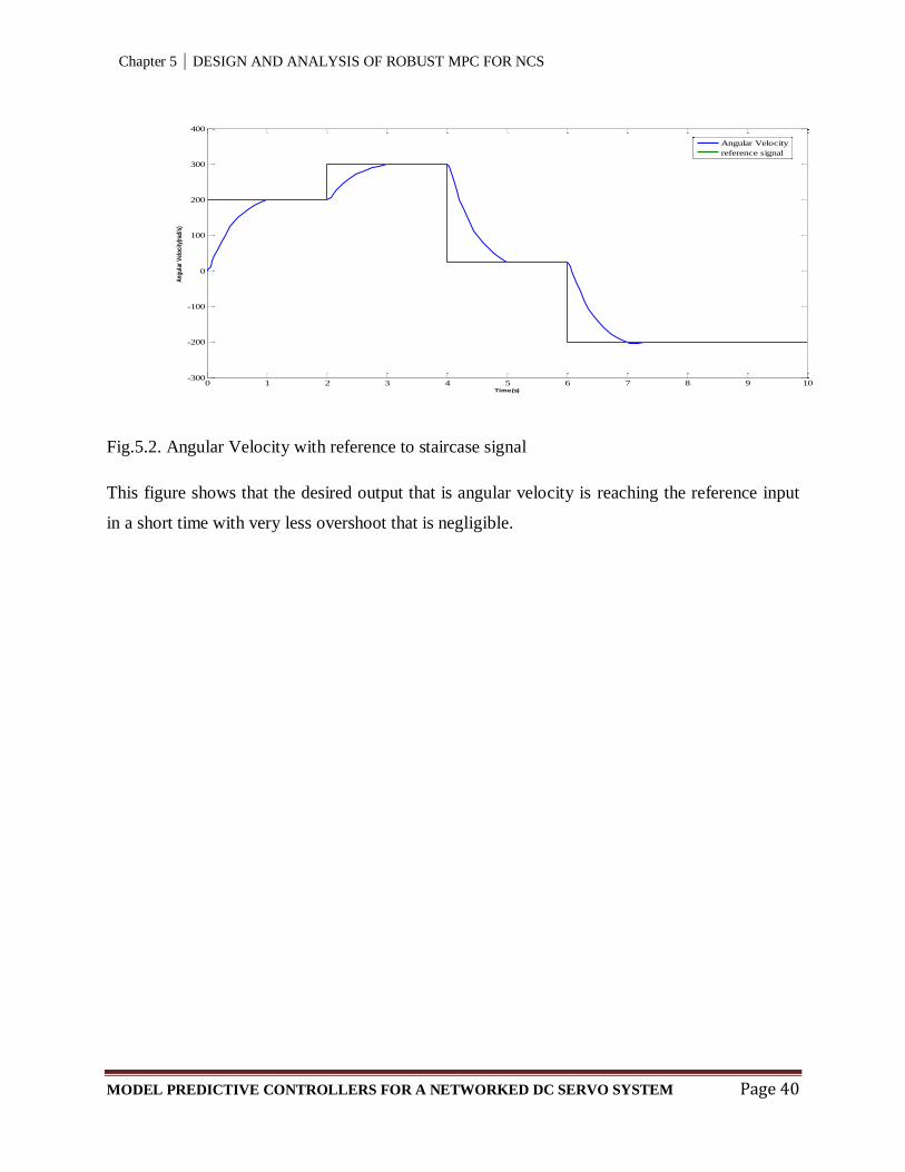
Fig.5.2. Angular Velocity with reference to staircase signal
This figure shows that the desired output that is angular velocity is reaching the reference input
in a short time with very less overshoot that is negligible.
0 1 2 3 4 5 6 7 8 9 10-300
-200
-100
0
100
200
300
400
Time(s)
Ang
ular
Vel
ocity
(rad
/s)
Angular Velocity
reference signal

CHAPTER 6
CONCLUSIONS AND
SUGGESTIONS FOR FUTURE
WORK

Chapter 6 CONCLUSIONS AND SUGGESTIONS FOR FUTURE WORK
MODEL PREDICTIVE CONTROLLERS FOR A NETWORKED DC SERVO SYSTEM Page 42
6.1 CONCLUSIONS
This thesis presents study on Network Control System and different type of delays associated
with it and also different Network Control Approaches, different Software, Platforms and
Systems used for NCS. As observed, communication network introduces time delays in the
control loop. These delays have effect on system stability and performance.
The objective of the present work is to study delay compensation schemes in the feedback loop.
Here different Model Predictive Control schemes have designed and studied to compensate the
network delays in network control systems.
In Chapter 4, the Standard MPC is designed and in Chapter 5, Robust MPC is designed and
analyses are done. From these, it is concluded that Standard MPC and Robust MPC both
compensating the delays but in Standard MPC there is some overshoot where as in Robust MPC,
overshoot is very less which is negligible compare to Standard MPC .The Robust MPC is
compensating the delays along with disturbances and constraints.
Also studied about TrueTime simulator and by using this TrueTime simulator the MPCs are
simulated and observed the outputs.
6.2 SUGGESTIONS FOR FUTURE WORK
In this thesis, Model Predictive Controllers are designed and applied to DC motor with the help
of TrueTime simulator which is a virtual model of real time network controlled system but it is
not applied in real time environment. Future work in this direction would involve application of
MPC in real time.

REFERENCES
MODEL PREDICTIVE CONTROLLERS FOR A NETWORKED DC SERVO SYSTEM Page 43
REFERENCES
[1] T.C. Yang: “Networked control system: a brief survey,” IEE Proc.-Control Theory Appl.,
Vol. 153, No. 4, July 2006.
[2] Tipsuwan, Y., and Chow, M.Y.: “Gain scheduler middleware: a methodology to enable
existing controllers for networked control and teleoperation – Part I: networked control,” IEEE
Trans. Ind. Electronics. , Vol.51, pp. 1218 – 1227, Dec. 2004.
[3] Gonzalo Farias, Robin De Keyser, Sebastián Dormido, and Francisco Esquembre:
„„Developing Networked Control Labs: A Matlab and Easy Java Simulations Approach,” IEEE
Trans. On Ind. Electronics, Vol. 57, No. 10, October 2010.
[4] Y. Tipsuwan, M.-Y. Chow: “Control methodologies in networked control systems,” Control
Engineering Practice 11, pp. 1099–1111, Feb. 2003.
[5] C.-F. Caruntu C. Lazar: “Robustly stabilizing model predictive control design for networked
control systems with an application to direct current motors,” IET Control Theory and Appl. Vol.
6, Iss.7, pp. 943–952, 2012
[6] Rachana Ashok Gupta, Mo-Yuen Chow: “Networked Control System: Overview and
Research Trends,” IEEE Trans. On Ind. Electronics, Vol. 57, No. 7, pp. 2527-2535, July 2010
[7] L. Zhang, C. Wang, and Y. Chen, “Stability and stabilization of a class of multimode linear
discrete-time systems with polytopic uncertainties, ”IEEE Trans. Ind. Electron., vol. 56, no. 9,
pp. 3684–3692, Sep. 2009.
[8] N. N. P. Mahalik and K. K. Kim, “A prototype for hardware-in-the-loop simulation of a
distributed control architecture,” IEEE Trans. Syst., vol. 38, no. 2, pp. 189–200, Mar. 2008.
[9] F.-L. Lian, J. K. Yook, D. M. Tilbury, and J. Moyne, “Network architecture and
communication modules for guaranteeing acceptable control and communication performance
for networked multi-agent systems,” IEEE Trans. Ind. Informat., vol. 2, no. 1, pp. 12–24, Feb.
2006.

REFERENCES
MODEL PREDICTIVE CONTROLLERS FOR A NETWORKED DC SERVO SYSTEM Page 44
[10] J. Nilsson. “Real-Time Control Systems with Delays,” PhD thesis, Department of
Automatic Control, Lund Institute of Technology,1998.
[11] S.Branicky, S. M. Phillips, W. Zhang, “Stability of Networked Control Systems: Explicit
Analysis of Delay,” IEEE Control Systems Magazine, vol. 21, pp. 84–99, February 2001.
[12] G.Walsh, H. Ye, and L. Bushnell, “Stability analysis of networked control systems,” Proc.
American Control Conference, pp. 2876-2880, June 1999.
[13] G.P.Liu and D.Rees and S.C. Chai, “Design and Practical Implementation of Networked
Predictive Control Systems,” IEEE ,7803-8812-7/05/$20.00 0, 2005.
[14] Tipsuwan, Y. & Chow, M.-Y., “Fuzzy logic microcontroller implementation for DC motor
speed control,” The 25th
annual conference of the IEEE industrial electronics society (IECON),
vol. 3, pp. 1271-1276, CA, 1999.
[15] Feng-Li Lian, J.R. Moyne and D.M. Tilbury, “Performance evaluation of control networks:
Ethernet, ControlNet, and DeviceNet,” IEEE Control Systems Magazine, vol.21, pp.66-83,
February 2001.
[16] Zhang W., “Stability analysis of networked control systems,” Ph.D Thesis, Case Western
Reserve University, 2001.
[17] P. E. Orukpe, “Basics of Model Predictive Control,” ICM, EEE-CAP, Imperial College,
London, April 2005.
[18] B. Raju, “Time delay Compensation Schemes with application to networked control
system,” M.Tech. Thesis, National Institute of Technology, Rourkela, 2009.
[19] Anand Singh, “Predictive Controller Design for Networked Systems” M.Tech. Thesis,
National Institute of Technology, Rourkela, 2012.