Dealer Set-up Instructions for 700 Series Finger Wheel Rakes
32
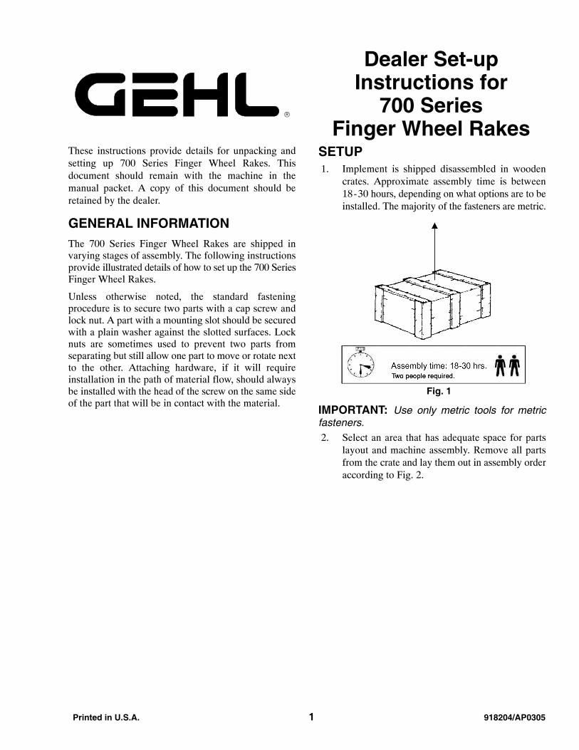
Printed in U.S.A. 1 918204/AP0305 Dealer Set-up Instructions for 700 Series Finger Wheel Rakes These instructions provide details for unpacking and setting up 700 Series Finger Wheel Rakes. This document should remain with the machine in the manual packet. A copy of this document should be retained by the dealer. GENERAL INFORMATION The 700 Series Finger Wheel Rakes are shipped in varying stages of assembly. The following instructions provide illustrated details of how to set up the 700 Series Finger Wheel Rakes. Unless otherwise noted, the standard fastening procedure is to secure two parts with a cap screw and lock nut. A part with a mounting slot should be secured with a plain washer against the slotted surfaces. Lock nuts are sometimes used to prevent two parts from separating but still allow one part to move or rotate next to the other. Attaching hardware, if it will require installation in the path of material flow, should always be installed with the head of the screw on the same side of the part that will be in contact with the material. SETUP 1. Implement is shipped disassembled in wooden crates. Approximate assembly time is between 18 - 30 hours, depending on what options are to be installed. The majority of the fasteners are metric. Fig. 1 IMPORTANT: Use only metric tools for metric fasteners. 2. Select an area that has adequate space for parts layout and machine assembly. Remove all parts from the crate and lay them out in assembly order according to Fig. 2.
Transcript of Dealer Set-up Instructions for 700 Series Finger Wheel Rakes
Printed in U.S.A. 1 918204/AP0305
Dealer Set-upInstructions for
700 SeriesFinger Wheel Rakes
These instructions provide details for unpacking andsetting up 700 Series Finger Wheel Rakes. Thisdocument should remain with the machine in themanual packet. A copy of this document should beretained by the dealer.
GENERAL INFORMATIONThe 700 Series Finger Wheel Rakes are shipped invarying stages of assembly. The following instructionsprovide illustrated details of how to set up the 700 SeriesFinger Wheel Rakes.
Unless otherwise noted, the standard fasteningprocedure is to secure two parts with a cap screw andlock nut. A part with a mounting slot should be securedwith a plain washer against the slotted surfaces. Locknuts are sometimes used to prevent two parts fromseparating but still allow one part to move or rotate nextto the other. Attaching hardware, if it will requireinstallation in the path of material flow, should alwaysbe installed with the head of the screw on the same sideof the part that will be in contact with the material.
SETUP 1. Implement is shipped disassembled in wooden
crates. Approximate assembly time is between18-30 hours, depending on what options are to beinstalled. The majority of the fasteners are metric.
Fig. 1
IMPORTANT: Use only metric tools for metricfasteners. 2. Select an area that has adequate space for parts
layout and machine assembly. Remove all partsfrom the crate and lay them out in assembly orderaccording to Fig. 2.

918204/AP0305 2 Printed in U.S.A.
Fig. 2
5, Fig. 4
5, Fig. 12
1, Fig. 12
6, Fig. 8
2, Fig. 3
2, Fig. 6
10, Fig. 14
13, Fig. 8
14, Fig. 8
6, Fig. 9
3, Fig. 9
4, Fig. 11
2, Fig. 10
5, Fig. 11
2, Fig. 11
1, Fig. 10
4, Fig. 16
14, Fig. 11
13, Fig. 8
2, Fig. 7
15, Fig. 11
1, Fig. 910, Fig. 8
5, Fig. 4
10, Fig. 14
14, Fig. 8
6, Fig. 9
5, Fig. 11
4, Fig. 11
2, Fig. 11
16, Fig. 10
15, Fig. 11
13, Fig. 8
12, Fig. 10
10, Fig. 8
6, Fig. 8
12, Fig. 10
5, Fig. 12
2, Fig. 82, Fig. 8
1, Fig. 12
7, Fig. 3
5, Fig. 9
4, Fig. 9
16, Fig. 71, Fig. 26
8, Fig. 6
7, Fig. 7
4, Fig. 9
4, Fig. 16
12, Fig. 3
26, Fig. 8
14, Fig. 11
5, Fig. 9
3, Fig. 9
13, Fig. 8
2, Fig. 8
3, Fig. 3 4, Fig. 3
4, Fig. 161, Fig. 7
2, Fig. 26
1, Fig. 41, Fig. 4

Printed in U.S.A. 3 918204/AP0305
REAR FRAME ASSEMBLY, 16, 18, AND 20-WHEEL (Fig. 3) 1. Supporting stands (not supplied) (1) are required for rake assembly. Raise the rear member (2) and connect the
two frame parts (3) and (4) using M14 x 40 bolts (5) with lock nuts (6). Do not fully tighten the nuts.
2. Assemble the slow-moving vehicle (SMV) bracket (21) to the clamp/bracket (22), over the rear member (2),by using cap screws (19), flat washers (20), flat washers (23), and hex nuts (24). Assemble SMV marker (16)to the slow-moving vehicle (SMV) bracket (21) by using cap screws (15), lock washers (17) and hex nuts (18).
3. Position the four reinforcement blades (7) as shown using M14 x 40 bolts (8) with lock nuts (9). Now proceedto tighten all above-mentioned nuts.
4. Connect the rear drawbar (12) and secure with M14 x 50 bolts (13) and lock nuts (14).
Fig. 3
7
8
2
7
5
6
3
21
20
2223
24
1817
16 15
19
9
4
1
1
12
13
14
7
918204/AP0305 4 Printed in U.S.A.
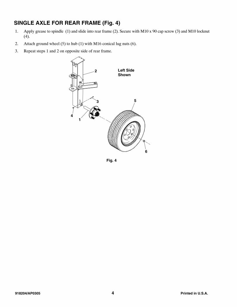
SINGLE AXLE FOR REAR FRAME (Fig. 4) 1. Apply grease to spindle (1) and slide into rear frame (2). Secure with M10 x 90 cap screw (3) and M10 locknut
(4).
2. Attach ground wheel (5) to hub (1) with M16 conical lug nuts (6).
3. Repeat steps 1 and 2 on opposite side of rear frame.
Fig. 4
6
5
2
1
3
4
Left SideShown

Printed in U.S.A. 5 918204/AP0305
TANDEM AXLE FOR REAR FRAME (Fig. 5) 1. Insert spring pin (1) through bushing (2) and pivot shaft (3).
2. Slide support hub (4) onto pivot shaft (3) with flange next to bushing (2).
3. Apply grease to pivot shaft (3) and slide into rear frame (5). Secure with M10 x 90 cap screw (6) and M10 locknut (7).
4. Position tandem beam (8) against support hub (4). The gusset on the rear frame (5) must be toward the rear ofthe cutout in the tandem beam (8). See 700 Gusset Alignment illustration below.
5. Attach tandem beam (8) to support hub (4) with M16 x 55 cap screws (9) and M16 conical lug nuts (10).
6. Attach two ground wheels (11) to tandem beam (8) with M16 conical lug nuts (10).
7. Repeat steps 1-6 on opposite side of rear frame.
Fig. 5

918204/AP0305 6 Printed in U.S.A.
DRAWBAR ASSEMBLY, 16, 18, AND 20-WHEEL (Fig. 6) 1. Connect the central drawbar (2) to the rear drawbar (1) using M14 x 40 bolts (4) and lock nuts (5). Do not use
the lower outside hole shown (3), because a longer bolt will later be placed through it.
2. Attach the support for cylinder (22) to the central drawbar (2) and the rear drawbar (1) by using cap screw (21)and lock nut (5).
3. Position the nylon pads (9) at the rear end of the front drawbar (8) using T.C.B. (thread cutting bolt) M8 x 20screws (10). Position the puffer (11) and slide the front drawbar (8) into the central drawbar (2). Position the0.6” (15 mm) thick nylon pads (12) and (13) as shown, blocking them with angle plates (14) and (15) using M6x 12 screws (16) and washers (17).
4. If the rake is a 16-finger wheel version, the pull drawbar 16 (7) will be mounted using M14 x 40 bolts (18) andlock nuts (19). If the rake is an 18 or 20-finger wheel version, the pull drawbar with wheel support (6) will bemounted.
5. If the rake is an 18 or 20-finger wheel version, insert grease fitting (20) into the pull drawbar with wheel support(6).
Fig. 6
10911
9
51
4
5
22
21
217
16
14
15
1213
19
6
18
3
7
10
20
3
Printed in U.S.A. 7 918204/AP0305
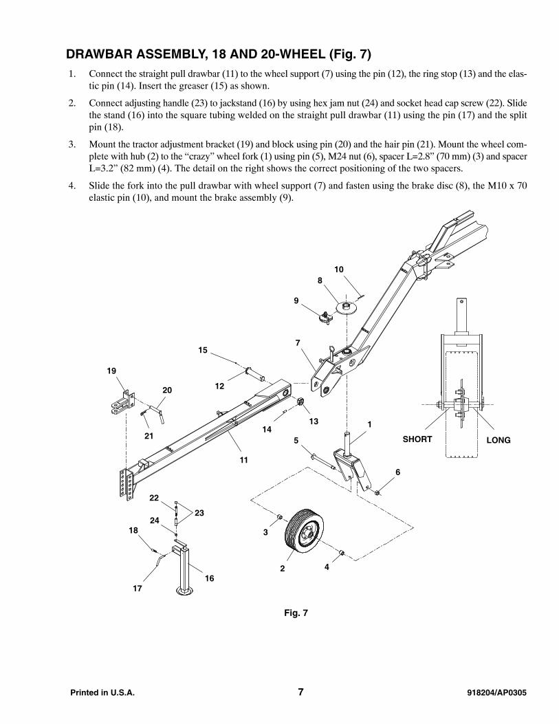
DRAWBAR ASSEMBLY, 18 AND 20-WHEEL (Fig. 7) 1. Connect the straight pull drawbar (11) to the wheel support (7) using the pin (12), the ring stop (13) and the elas-
tic pin (14). Insert the greaser (15) as shown.
2. Connect adjusting handle (23) to jackstand (16) by using hex jam nut (24) and socket head cap screw (22). Slidethe stand (16) into the square tubing welded on the straight pull drawbar (11) using the pin (17) and the splitpin (18).
3. Mount the tractor adjustment bracket (19) and block using pin (20) and the hair pin (21). Mount the wheel com-plete with hub (2) to the “crazy” wheel fork (1) using pin (5), M24 nut (6), spacer L=2.8” (70 mm) (3) and spacerL=3.2” (82 mm) (4). The detail on the right shows the correct positioning of the two spacers.
4. Slide the fork into the pull drawbar with wheel support (7) and fasten using the brake disc (8), the M10 x 70elastic pin (10), and mount the brake assembly (9).
Fig. 7
7
108
9
113
6
12
15
14
11
5
2324
22
18
1716
3
20
21
19
2
SHORT LONG
4

918204/AP0305 8 Printed in U.S.A.
WING FRAME ASSEMBLY, 16, 18, AND 20-WHEEL (Fig. 8) 1. Mount the rear frame flex bracket (2) to the rear support (1) using pin (3) and elastic pin (4). Insert greaser (5)
in the pin. With the use of a supporting stand, connect the rear frame (6) to the rear frame flex bracket (2) andfasten with the M30 bolt L=5.51” (140 mm) (7), self-locking nylon nut (8), and grease fitting (9).
2. Connect the central frame (10) and fasten with M14 x 40 bolts (11) and lock nuts (12). In the 18 and 20-Wheelversions, the central frame has a flex attachment (26). Mount the “crazy” wheel fork as shown. Follow the in-structions given on the previous page. Connect the threaded handle (22), hexagonal nut (25), knob w/cover (24),and the cap screw (23). Complete the same assembly operations on the right side of the rake.
Fig. 8
26
2119
2010
6
22
25
23
24
17
13
18
11
12
15
14 16
7
2
4
3
5
1
8
9

Printed in U.S.A. 9 918204/AP0305
ADJUSTMENT ARM ASSEMBLY, 16, 18, AND 20-WHEEL (Fig. 9) 1. Mount the arm frame attachment (6) onto the central frame using M12 x 40 bolts (13) and lock nuts (12).
2. Assemble the sliding sleeve (1) as shown. Position the nylon pads (14) and (15) the plate that closes the slidingsleeve (2) and fasten with M10 x 30 screws (11).
3. Connect the hinges for panto arm (5) to the sliding sleeve (1) and to the arm frame attachment (6) with L=6.85”(174 mm) pins (7) and nylon M24 self-locking nuts (9). Insert grease fitting (16) into the pins (7). Connect thepanto arm hinges (5) to the panto blades (3) using the L=3.74” (95 mm) pin (8) and the nylon M24 self-lockingnuts (9).
4. Connect the opening arm (4) to the front drawbar (17) and arm frame attachment (6) using the L=3.74” (95 mm)pin (8), the nylon M24 self-locking nuts (9), and the spacers (10).
Fig. 9
Key stock
facing the
middle of
the rake
Direct anchors
for hose clamps
out and forward
115
14
7
9
5
2
11
78
9
3
9
6
8
10
9
48
10
10
9
12
13
5
16
16
10
17

918204/AP0305 10 Printed in U.S.A.
WING FRAME ASSEMBLY, 16-WHEEL (Fig. 10) 1. Assemble the two rake wheel extensions (12) using M14 x 40 bolts (14) and lock nuts (15). Attach the handle
(20) to the knob (22) and to the wing frame by using hex jam nut (21) and socket head cap screw (23).
2. Position the lift tubes (1), (2) and (16) into the supports welded on the central frame LH (13) placing all the bush-ings (3, 9, 17), supports (4, 5), and the lift tube ring (6) as shown.
3. Block all the bushings with M8 x 50 bolts (7), nylon self-locking nuts (8) and grease fitting M10 x 1 (10) wherenecessary. Position the pivot safety for parking (18) in the support and fasten with pin/lock (19).
4. Follow the same instructions on the right side of the rake.
NOTE: To check that the assembly of the lift tubes is correct, verify that the distance between each bush-ing and the spring attachment is 35.4” (900 mm).
Fig. 10
20
21
22
23
1918
4
8
9
3
7
17
6
210
5
LEFT SIDE
12 141513
17
16
35.4” (900 M)

Printed in U.S.A. 11 918204/AP0305
WING FRAME ASSEMBLY, 18 AND 20-WHEEL (Fig. 11) 1. Position the two rake-wheel extension (2) into the housing on the 18 and 20-Wheel central frame (1) and fasten
using the M30 pin (3). Install grease zerk (7) into the end of pin (3). Position the blades (4) and (5) on the frameas shown and fasten it in the center using the M30 nut (6). Fasten the blades to the frames (1) using M12 x 30bolts (8) and M12 lock nuts (9).
2. Connect the rigid two rake-wheel extension (10) using M14 x 40 bolts (12) and lock nuts (13). Mount the angledwheel support (14). Position the “crazy” wheel assembly (15) into the angled wheel support and fasten with thedisk brake (16), the elastic pin 10 x 70 (18), and mount the brake assembly (17).
3. Insert the grease fitting (32) between the bushing (25) and lift tube (20). Assemble the lift tubes (19), (20), (21)and (22) placing them within their supports welded on the frames and position all the bushing and the supports(24), (25), (26), (27) and (28) as shown. Connect the lift tube joint (33). Block all lift tubes with screws M8 x50 (30) and nylon self-locking nuts (31).
NOTE: When assembling a hay rake with 18 finger-rake wheels, use the bushing that has four holes andan ear welded on it (29), to limit the oscillation of the last lift tube L=35.4” (900 mm) (23), which is only onthe 18-Wheel model.
4. Position the pivot safety for parking (34) in the support and fasten with pin/lock (35). Follow the same instruc-tions on the right side of the rake.
NOTE: To check the correct assembly of the lift tubes, verify that the distance between each bushingand the spring attachment is 35.4” (900 mm).
Fig. 11
17
16
18
15
21
30
20
30
26
30
24
27
35 34
3128
25
32
333
2
13
98 4
5
6 7
8
1
22
28
19
109
1412
13
23
29

918204/AP0305 12 Printed in U.S.A.
WINDROW WIDTH ADJUSTMENT DEVICE ASSEMBLY, 16, 18, AND20-WHEEL (Fig. 12) 1. Place the rear support for the arm carrying rake wheel (1) onto the wheel assembly (2). Using the pivot carrying
pulley (3) nylon self-locking nut M24 (4). Now assemble the rear arm that carries the rake wheel (5), and securewith a screw M20 x 150 (6) and a lock nut (7).
2. Pre-assemble the spring (8) with the two attachments (9). Screw the turnbuckle (10) onto nut M14 (11) to tightenthe coupling, and then onto the nut which is welded on the rear lift tube.
3. Connect the spring assembled to the turnbuckle with a 0.31” (8 mm) U-shackle (12). Slide the wire rope intoposition (13) and then connect the two pulleys (14) to the pivots as shown. Secure the pulleys with a washer M25(15) and cotter pin M5 x 40 (16). Connect one end of the wire rope to the spring assembly with a 0.31” (8 mm)U-shackle (12). Connect the other end of the wire rope to the arm carrying the rake wheel with a 0.31” (8 mm)U-shackle (12).
4. Install the assembled turnbuckle (17) as shown. Attach it to the rear support of the arm carrying the rake wheel(1) by means of a 0.16” (4 mm) “R” cotter pin (18). Attach it to the support, between the two welded ears witha pivot (19) and a 0.16” (4 mm) “R” cotter pin (20).
Fig. 12
15
10
14
12
12
1513
12
16
20
163
18
6
7
17
5
1
4
8
9
19
2
11

Printed in U.S.A. 13 918204/AP0305
HYDRAULIC OPENING-CLOSING SYSTEM ASSEMBLY, 16, 18, AND20-WHEEL (Fig. 13) 1. Place the hydraulic cylinder (2) between the two welded ears on the drawbar and on the sliding opening. Secure
with two pivots (16) and four cotter pins M5 x 40 (17).
2. Attach the cylinder’s safety bar (18) with two screws M14 x 50 (19) and two lock nuts (20) to the two free holesleft on the drawbar plate as shown. Assemble the two shaped fittings (8) onto the cylinder outlets and connectthe hydraulic opening hoses (1), length = 32.8’ (10 m) for the 18 and 20-Wheel hay rakes, and length = 26.2’(8 m) for the 16-Wheel hay rake. Place the nylon hose conveyor belt (3) on top of the hydraulic hoses and secureonto the drawbar as shown using screws M8 x 25 (14), washers (15) and nylon self-locking nuts (7).
3. Attach the opening hose onto the length of the drawbar with clamps for two hoses and a clamp (9), cover (10)and screw M8 x 35 (11). Attach the hose on the side of the drawbar with clamps for one hose, cover (12), andscrews M6 x 25 (13).
4. Install couplers (4), o-rings (5) and fittings (6) on the ends of hoses (1) as shown.
Fig. 13
3
111
10
9
14
715
12
13 8
2
19
17
16
20
18
4
654
918204/AP0305 14 Printed in U.S.A.
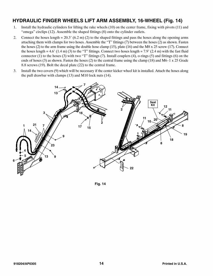
HYDRAULIC FINGER WHEELS LIFT ARM ASSEMBLY, 16-WHEEL (Fig. 14) 1. Install the hydraulic cylinders for lifting the rake wheels (10) on the center frame, fixing with pivots (11) and
“omega” circlips (12). Assemble the shaped fittings (8) onto the cylinder outlets.
2. Connect the hoses length = 20.3’ (6.2 m) (2) to the shaped fittings and pass the hoses along the opening armsattaching them with clamps for two hoses. Assemble the “T” fittings (7) between the hoses (2) as shown. Fastenthe hoses (2) to the arm frame using the double hose clamp (15), plate (16) and the M8 x 25 screw (17). Connectthe hoses length = 4.6’ (1.4 m) (3) to the “T” fittings. Connect two hoses length = 7.9’ (2.4 m) with the fast fluidconnector (1) to the hoses (3) with two “T” fittings (7). Install couplers (4), o-rings (5) and fittings (6) on theends of hoses (3) as shown. Fasten the hoses (2) to the central frame using the clamp (18) and M6-1 x 25 Grade8.8 screws (19). Bolt the decal plate (22) to the central frame.
3. Install the two covers (9) which will be necessary if the center kicker wheel kit is installed. Attach the hoses alongthe pull drawbar with clamps (13) and M10 lock nuts (14).
Fig. 14
1
3
7
16
9
17 15
2
714
13
2
10
12
11
8
19
188
4
5
6
22
20
SealKit
23
21
14
13
11
9
Printed in U.S.A. 15 918204/AP0305
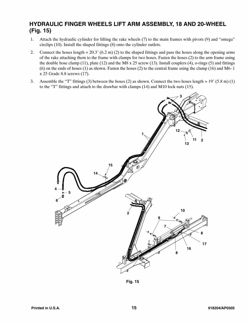
HYDRAULIC FINGER WHEELS LIFT ARM ASSEMBLY, 18 AND 20-WHEEL(Fig. 15) 1. Attach the hydraulic cylinder for lifting the rake wheels (7) to the main frames with pivots (9) and “omega”
circlips (10). Install the shaped fittings (8) onto the cylinder outlets.
2. Connect the hoses length = 20.3’ (6.2 m) (2) to the shaped fittings and pass the hoses along the opening armsof the rake attaching them to the frame with clamps for two hoses. Fasten the hoses (2) to the arm frame usingthe double hose clamp (11), plate (12) and the M8 x 25 screw (13). Install couplers (4), o-rings (5) and fittings(6) on the ends of hoses (1) as shown. Fasten the hoses (2) to the central frame using the clamp (16) and M6-1x 25 Grade 8.8 screws (17).
3. Assemble the “T” fittings (3) between the hoses (2) as shown. Connect the two hoses length = 19’ (5.8 m) (1)to the “T” fittings and attach to the drawbar with clamps (14) and M10 lock nuts (15).
Fig. 15
3
12
1311 2
1
45
6
15
14
10
8
9
7
168
17
2
918204/AP0305 16 Printed in U.S.A.
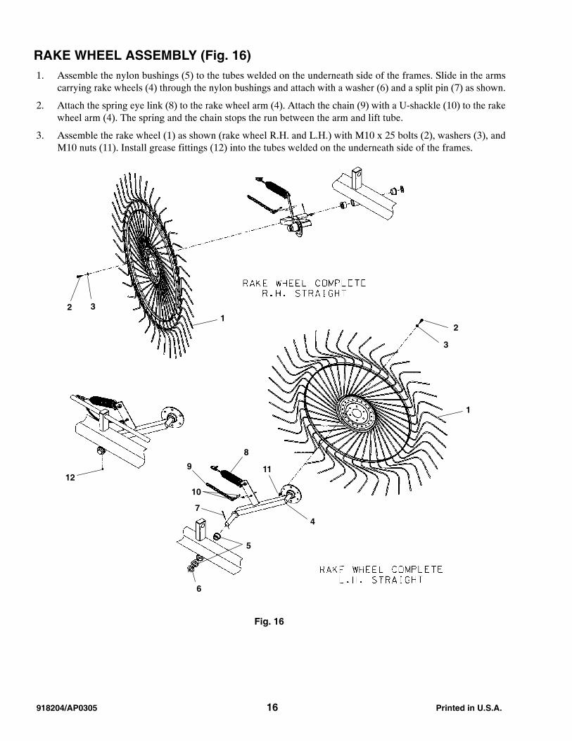
RAKE WHEEL ASSEMBLY (Fig. 16) 1. Assemble the nylon bushings (5) to the tubes welded on the underneath side of the frames. Slide in the arms
carrying rake wheels (4) through the nylon bushings and attach with a washer (6) and a split pin (7) as shown.
2. Attach the spring eye link (8) to the rake wheel arm (4). Attach the chain (9) with a U-shackle (10) to the rakewheel arm (4). The spring and the chain stops the run between the arm and lift tube.
3. Assemble the rake wheel (1) as shown (rake wheel R.H. and L.H.) with M10 x 25 bolts (2), washers (3), andM10 nuts (11). Install grease fittings (12) into the tubes welded on the underneath side of the frames.
12 3
3
2
1
12
8
4
119
10
7
5
6
Fig. 16
Printed in U.S.A. 17 918204/AP0305
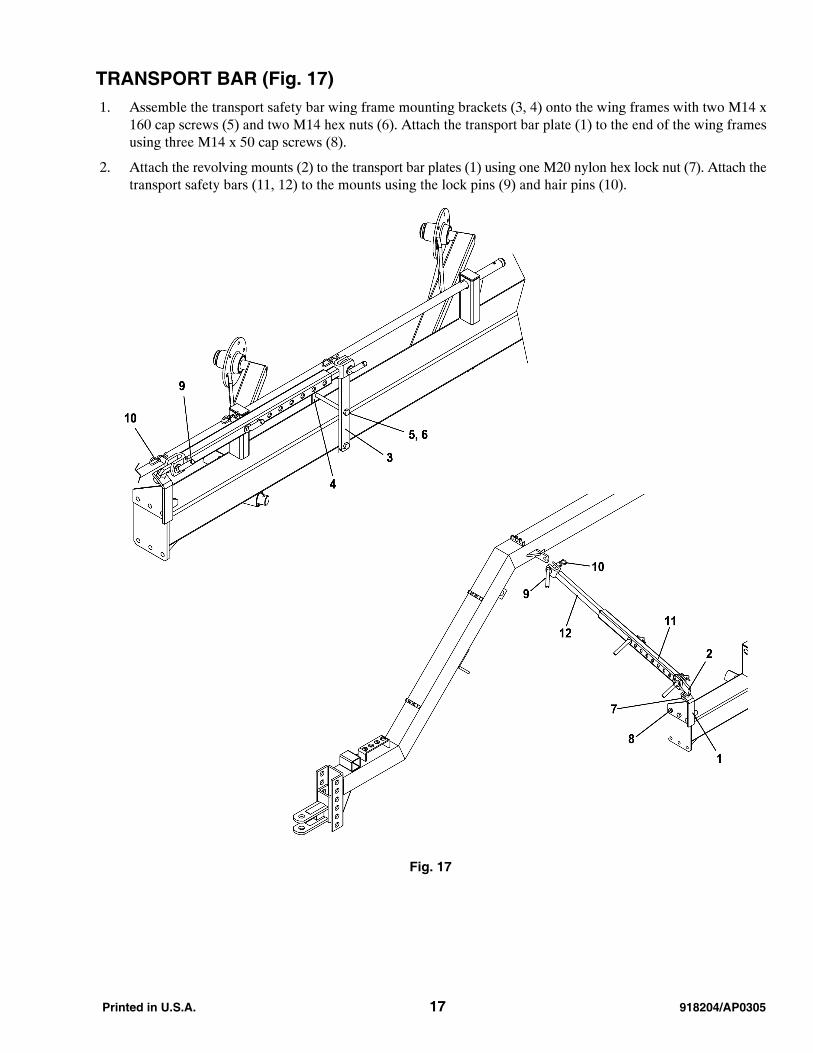
TRANSPORT BAR (Fig. 17) 1. Assemble the transport safety bar wing frame mounting brackets (3, 4) onto the wing frames with two M14 x
160 cap screws (5) and two M14 hex nuts (6). Attach the transport bar plate (1) to the end of the wing framesusing three M14 x 50 cap screws (8).
2. Attach the revolving mounts (2) to the transport bar plates (1) using one M20 nylon hex lock nut (7). Attach thetransport safety bars (11, 12) to the mounts using the lock pins (9) and hair pins (10).
Fig. 17
918204/AP0305 18 Printed in U.S.A.
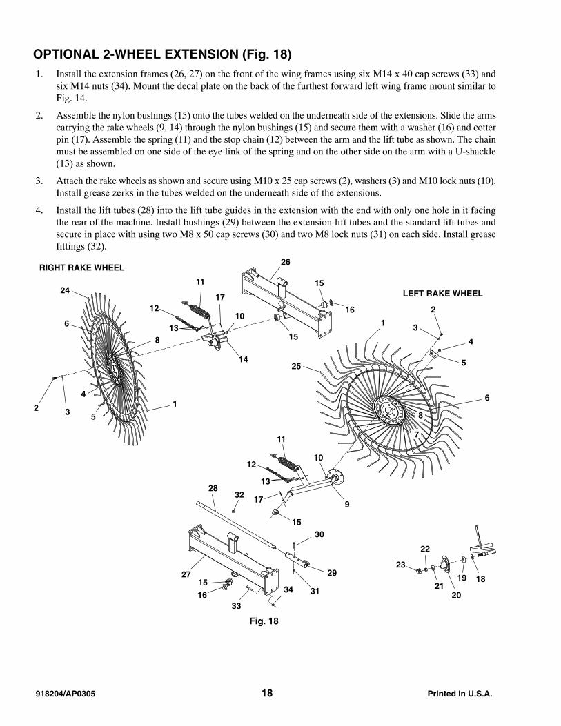
OPTIONAL 2-WHEEL EXTENSION (Fig. 18) 1. Install the extension frames (26, 27) on the front of the wing frames using six M14 x 40 cap screws (33) and
six M14 nuts (34). Mount the decal plate on the back of the furthest forward left wing frame mount similar toFig. 14.
2. Assemble the nylon bushings (15) onto the tubes welded on the underneath side of the extensions. Slide the armscarrying the rake wheels (9, 14) through the nylon bushings (15) and secure them with a washer (16) and cotterpin (17). Assemble the spring (11) and the stop chain (12) between the arm and the lift tube as shown. The chainmust be assembled on one side of the eye link of the spring and on the other side on the arm with a U-shackle(13) as shown.
3. Attach the rake wheels as shown and secure using M10 x 25 cap screws (2), washers (3) and M10 lock nuts (10).Install grease zerks in the tubes welded on the underneath side of the extensions.
4. Install the lift tubes (28) into the lift tube guides in the extension with the end with only one hole in it facingthe rear of the machine. Install bushings (29) between the extension lift tubes and the standard lift tubes andsecure in place with using two M8 x 50 cap screws (30) and two M8 lock nuts (31) on each side. Install greasefittings (32).
Fig. 18
26
16
15
15
2411
13
12
8
6
17
14
10
13 5
4
2
25
6
5
2
31
4
23
22
1819
2021
13
12
11
9
10
17
15
7
8
RIGHT RAKE WHEEL
LEFT RAKE WHEEL
3228
27
30
29
3115
1633
34
Printed in U.S.A. 19 918204/AP0305
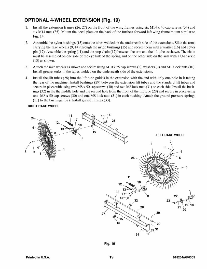
OPTIONAL 4-WHEEL EXTENSION (Fig. 19) 1. Install the extension frames (26, 27) on the front of the wing frames using six M14 x 40 cap screws (34) and
six M14 nuts (35). Mount the decal plate on the back of the furthest forward left wing frame mount similar toFig. 14.
2. Assemble the nylon bushings (15) onto the tubes welded on the underneath side of the extensions. Slide the armscarrying the rake wheels (9, 14) through the nylon bushings (15) and secure them with a washer (16) and cotterpin (17). Assemble the spring (11) and the stop chain (12) between the arm and the lift tube as shown. The chainmust be assembled on one side of the eye link of the spring and on the other side on the arm with a U-shackle(13) as shown.
3. Attach the rake wheels as shown and secure using M10 x 25 cap screws (2), washers (3) and M10 lock nuts (10).Install grease zerks in the tubes welded on the underneath side of the extensions.
4. Install the lift tubes (28) into the lift tube guides in the extension with the end with only one hole in it facingthe rear of the machine. Install bushings (29) between the extension lift tubes and the standard lift tubes andsecure in place with using two M8 x 50 cap screws (30) and two M8 lock nuts (31) on each side. Install the bush-ings (32) in the the middle hole and the second hole from the front of the lift tube (28) and secure in place usingone M8 x 50 cap screws (30) and one M8 lock nuts (31) in each bushing. Attach the ground pressure springs(11) to the bushings (32). Install grease fittings (33).
Fig. 19
2411
13
12
8
6
17
14
13 5
42
25
6
5
2
31
4
231819
2021
13
12
11
9
10
1715
7
8
RIGHT RAKE WHEEL
LEFT RAKE WHEEL
32
28
30
29
31
1516
33
27
26
1615
15
3435
10
22
15
918204/AP0305 20 Printed in U.S.A.
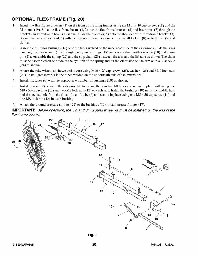
OPTIONAL FLEX-FRAME (Fig. 20) 1. Install the flex-frame brackets (3) on the front of the wing frames using six M14 x 40 cap screws (18) and six
M14 nuts (19). Slide the flex-frame beams (1, 2) into the flex-frame brackets (3) and insert pins (7) through thebrackets and flex-frame beams as shown. Slide the braces (4, 5) onto the shoulder of the flex-frame bracket (3).Secure the ends of braces (4, 5) with cap screws (15) and lock nuts (16). Install locknut (8) on to the pin (7) andtighten.
2. Assemble the nylon bushings (18) onto the tubes welded on the underneath side of the extensions. Slide the armscarrying the rake wheels (20) through the nylon bushings (18) and secure them with a washer (19) and cotterpin (21). Assemble the spring (22) and the stop chain (23) between the arm and the lift tube as shown. The chainmust be assembled on one side of the eye link of the spring and on the other side on the arm with a U-shackle(24) as shown.
3. Attach the rake wheels as shown and secure using M10 x 25 cap screws (25), washers (26) and M10 lock nuts(27). Install grease zerks in the tubes welded on the underneath side of the extensions.
4. Install lift tubes (6) with the appropriate number of bushings (10) as shown.
5. Install bracket (9) between the extension lift tubes and the standard lift tubes and secure in place with using twoM8 x 50 cap screws (11) and two M8 lock nuts (12) on each side. Install the bushings (10) in the the middle holeand the second hole from the front of the lift tube (6) and secure in place using one M8 x 50 cap screw (11) andone M8 lock nut (12) in each bushing.
6. Attach the ground pressure springs (22) to the bushings (10). Install grease fittings (17).
IMPORTANT: Before operation, the 5th and 6th ground wheel kit must be installed on the end of theflex-frame beams.
Fig. 20
13
12
11
2
7
14
9
6
10
1615
4 3
58
1
17
1819
1819
2720
24
23
2221
2625
Printed in U.S.A. 21 918204/AP0305
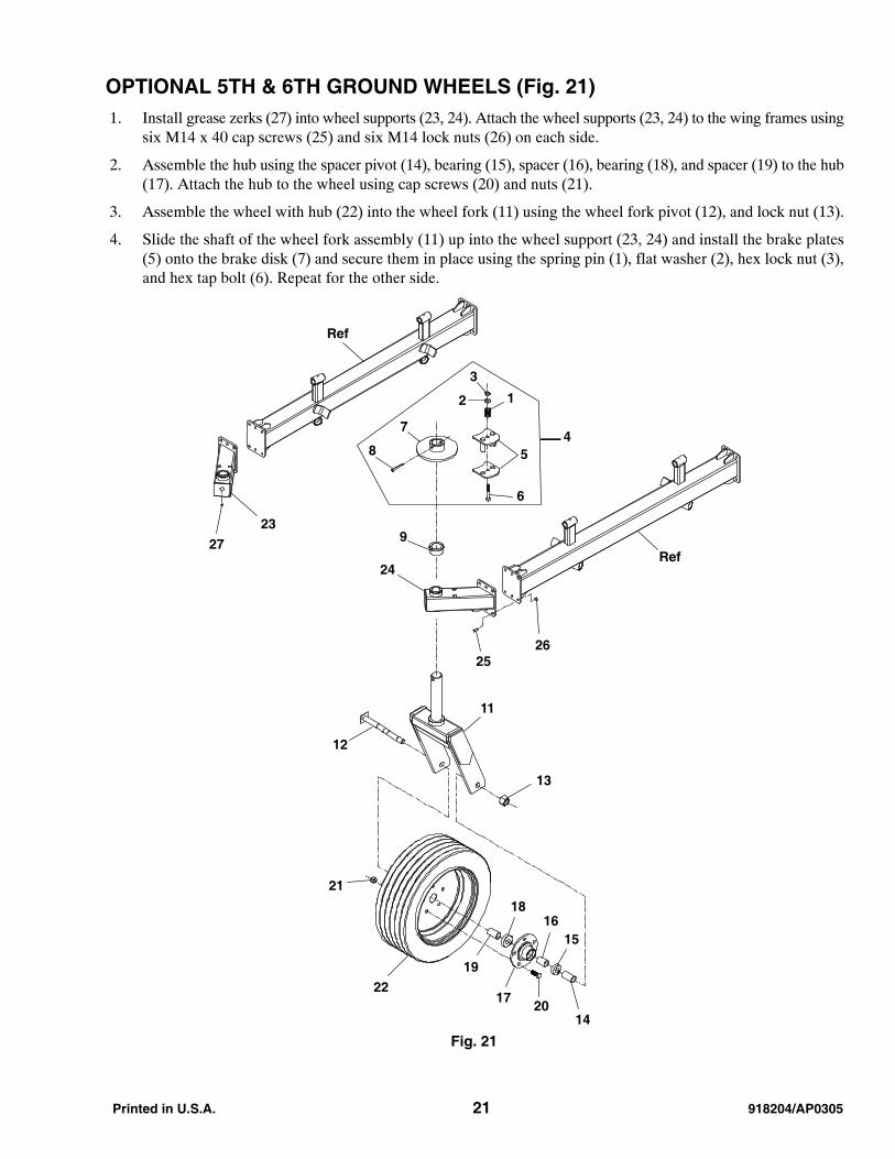
OPTIONAL 5TH & 6TH GROUND WHEELS (Fig. 21) 1. Install grease zerks (27) into wheel supports (23, 24). Attach the wheel supports (23, 24) to the wing frames using
six M14 x 40 cap screws (25) and six M14 lock nuts (26) on each side.
2. Assemble the hub using the spacer pivot (14), bearing (15), spacer (16), bearing (18), and spacer (19) to the hub(17). Attach the hub to the wheel using cap screws (20) and nuts (21).
3. Assemble the wheel with hub (22) into the wheel fork (11) using the wheel fork pivot (12), and lock nut (13).
4. Slide the shaft of the wheel fork assembly (11) up into the wheel support (23, 24) and install the brake plates(5) onto the brake disk (7) and secure them in place using the spring pin (1), flat washer (2), hex lock nut (3),and hex tap bolt (6). Repeat for the other side.
Fig. 21
3
5
2
4
1
6
9
8
7
13
21
12
11
19
22
1816
17
15
2014
24
23
Ref
Ref
2625
27

918204/AP0305 22 Printed in U.S.A.
HYDRAULIC FINGER WHEELS LIFT ARM ASSEMBLY, 12, 14, AND16-WHEEL WITHOUT SPLITTER WHEELS (Fig. 22)
NOTE: See CENTER SPLITTER WHEELS ASSEMBLY, 12, 14, AND 16-WHEEL (Fig. 24) for set-upinstructions for hydraulic finger wheel lift arm assembly 12, 14, and 16-Wheel with splitter wheels.
1. Install the hydraulic cylinders (10) for the lifting of the rake wheels on the wing frame member, fixing the pivots(11) and “omega” circlips (12) assembled to the 90-degree fittings (8) into the cylinder outlets, connect the hoses(2), length = 20.3’ (6.2 m), to the 90-degree fittings (8) and route the hoses along the opening arms of the rake,fixing them to the frame with clamps for two hoses (15), (16) and M6 x 35 (17) bolts.
2. Fasten the hoses to the “T” fittings (7) at the pull drawbar. Position the center connection of the “T” fittings (7)forward. Connect the hose (2) from the rod end of the right and left lift cylinder to the top “T” fitting (7). Connectthe hose (2) from the piston end of the right and left lift cylinders to the bottom “T” fitting (7).
3. Alongside each lift cylinder, clamp the hose from the piston end with a single hose clamp (18) and M6 x 25 (19)screws as shown. At the center connection of the “T” fittings (7) to which you just attached hoses (2), fastenhoses (3), length = 4.6’ (1.4 m), and lay the hose forward along the drawbar. Secure hoses (3) with clamps (13)and locknuts (14).
4. Fasten other “T” fittings (7) to the other end of hoses (3). Fasten hoses (1), length = 7.8’ (2.4 m), with the quickcouplers already attached, to the other end of the “T” fittings (7) to which you just attached hoses (3). Lay hoses(1) forward along the drawbar, and secure with clamps (13), locknuts (14), and a tie (23). Place the decal plate(21) between the locknut (14) and the clamp (13). Place covers (9) over the remaining open ports of the “T”fittings (7).
Fig. 22
1
3
7
16
9
17 152
714
13
2
10
12
11
8
19
188
4
5
6
22
20
SealKit
23
21
14
13
11
9

Printed in U.S.A. 23 918204/AP0305
HYDRAULIC FINGER WHEELS LIFT ARM ASSEMBLY, 18 AND 20-WHEELWITHOUT SPLITTER WHEELS (Fig. 23)NOTE: See CENTER SPLITTER WHEELS ASSEMBLY, 18, AND 20-WHEEL (Fig. 26) for set-up in-structions for hydraulic finger wheel lift arm assembly 18, and 20-Wheel with splitter wheels.
1. Install the hydraulic cylinders (7) for the lifting of the rake wheels, on the wing frame member, fixing the pivots(9) and “omega” cotter pins (10). Assembled to the 90-degree fittings (8) into the cylinder outlets, connect thehoses (2), length = 20.3’ (6.2 m), to the 90-degree fittings and pass the hoses along the “opening arms” of therake, fixing them to the frame with clamps for two hoses (11), (12) and M6 x 35 screws (13).
2. Fasten the hoses (2) to the “T” fittings (3) at the pull drawbar. Position the center connections of the “T” fittings(3) forward. Connect the hose (2) from the rod end of the right and left lift cylinder to the top “T” fitting (3).Connect the hose (2) from the piston end of the right and left lift cylinders to the bottom “T” fitting (3).
3. Along side each lift cylinder, clamp the hose from the piston end with a single hose clamp (16) and M6 x 25screws (17) as shown. At the center connections of the “T” fittings (3) to which you attached hoses (2), fastenhoses (1), length = 20.3’ (6.2 m), and lay the hoses forward along the drawbar. Secure hoses (1) with clamps(14) and locknuts (15).
Fig. 23
3
12
1311
21
45
6
15
14
10
8
9
7
168
17
2
7
SealKit
18

918204/AP0305 24 Printed in U.S.A.
CENTER SPLITTER WHEELS ASSEMBLY, 12, 14, AND 16-WHEEL (Fig. 24) 1. Assemble the sliding member for the central wheel (4) to the pull drawbar. Assemble the splitter wheel lift cylin-
der to the pull drawbar and sliding for central wheel (4) using pins (6) and circlips (7).
2. Assemble the wheel arm (1) to the pull drawbar using the pivot (2), spring pin (12), and ring stop (3). Insertgrease fitting (13) as shown.
NOTE: Assemble with tab for the chain and spring anchor up (location “A” in Fig. 24). Note the orientationof the wheel arm (1).
3. Pre-assemble the spring (8) with the two attachments (9). Attach the chain (10) to the U-shackles (11), and thespring attachments (9) to the U-shackles (11). Attach the U-shackle (11) to the wheel arm (1), and two U-shackles (11) to the sliding for central wheel (4).
4. Continued on the next page.
Fig. 24
13
2
13
67
5
4
11
10
118
9
12
Splitter Wheel Kit(12, 14, 16-Wheel)
8
9
A

Printed in U.S.A. 25 918204/AP0305
CENTER SPLITTER WHEELS ASSEMBLY, 12, 14, AND 16-WHEEL (cont.)(Fig. 25) 5. Fasten hoses (1) to adapters (2) as shown. Fasten adapter (2) to the rod end of the splitter wheel lift cylinder as
shown.
6. Fasten adapter (2) to the washers (4), lockout valve (5), and fitting (3) as shown. Fasten fitting (3) to splitterwheel lift cylinder.
7. Fasten the hose from the rod end of the splitter wheel lift cylinder to the “T” that is in the hose line, routed fromthe rod end of the lift cylinder on the main rake.
8. Route the hose from lockout valve to the “T” in the main rake line, routed to the rod end of the raking wheellift cylinder.
9. Assemble the rake wheels (9, 10) to the wheel arm (12) using cap screws (6), flat washers (7), and hex nuts (8).
10. Assemble the windshields (11) to the rake wheels (9, 10). Secure with wire ties looped through holes in wind-shield and around tines.
NOTE: The center splitter raking wheels are smaller in diameter than the main raking wheels. Assemblewith larger diameter dish plate toward wheel hub and the tine end at the bottom of the wheel should bedirected slightly forward.
Fig. 25
Splitter Wheel Kit(12, 14, 16-Wheel)
8
1110
7
612
2
9
11
1
1
24
3
5
918204/AP0305 26 Printed in U.S.A.
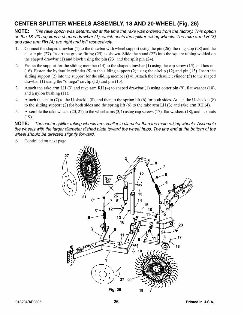
CENTER SPLITTER WHEELS ASSEMBLY, 18 AND 20-WHEEL (Fig. 26)NOTE: This rake option was determined at the time the rake was ordered from the factory. This optionon the 18-20 requires a shaped drawbar (1), which nests the splitter raking wheels. The rake arm LH (3)and rake arm RH (4) are right and left respectively.
1. Connect the shaped drawbar (1) to the drawbar with wheel support using the pin (26), the ring stop (28) and theelastic pin (27). Insert the grease fitting (25) as shown. Slide the stand (22) into the square tubing welded onthe shaped drawbar (1) and block using the pin (23) and the split pin (24).
2. Fasten the support for the sliding member (14) to the shaped drawbar (1) using the cap screw (15) and hex nut(16). Fasten the hydraulic cylinder (5) to the sliding support (2) using the circlip (12) and pin (13). Insert thesliding support (2) into the support for the sliding member (14). Attach the hydraulic cylinder (5) to the shapeddrawbar (1) using the “omega” circlip (12) and pin (13).
3. Attach the rake arm LH (3) and rake arm RH (4) to shaped drawbar (1) using cotter pin (9), flat washer (10),and a nylon bushing (11).
4. Attach the chain (7) to the U-shackle (8), and then to the spring lift (6) for both sides. Attach the U-shackle (8)to the sliding support (2) for both sides and the spring lift (6) to the rake arm LH (3) and rake arm RH (4).
5. Assemble the rake wheels (20, 21) to the wheel arms (3,4) using cap screws (17), flat washers (18), and hex nuts(19).
NOTE: The center splitter raking wheels are smaller in diameter than the main raking wheels. Assemblethe wheels with the larger diameter dished plate toward the wheel hubs. The tine end at the bottom of thewheel should be directed slightly forward.
6. Continued on next page.
Fig. 26
21
3
6
8 7
12
13
5
1
87
8
6
10
9
11
4119
2
13
12
10
1415
16
20
19
17
18
11
11
SealKit
26
27
27
25
22
23
24
Printed in U.S.A. 27 918204/AP0305
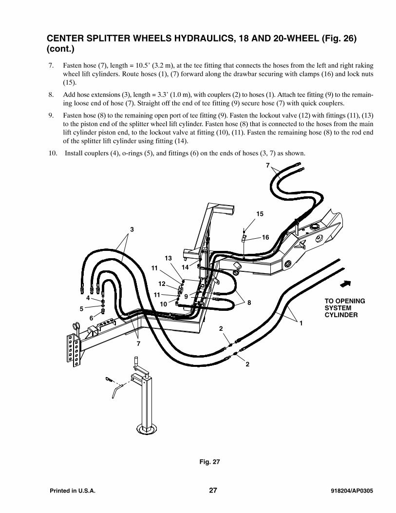
CENTER SPLITTER WHEELS HYDRAULICS, 18 AND 20-WHEEL (Fig. 26)(cont.)
7. Fasten hose (7), length = 10.5’ (3.2 m), at the tee fitting that connects the hoses from the left and right rakingwheel lift cylinders. Route hoses (1), (7) forward along the drawbar securing with clamps (16) and lock nuts(15).
8. Add hose extensions (3), length = 3.3’ (1.0 m), with couplers (2) to hoses (1). Attach tee fitting (9) to the remain-ing loose end of hose (7). Straight off the end of tee fitting (9) secure hose (7) with quick couplers.
9. Fasten hose (8) to the remaining open port of tee fitting (9). Fasten the lockout valve (12) with fittings (11), (13)to the piston end of the splitter wheel lift cylinder. Fasten hose (8) that is connected to the hoses from the mainlift cylinder piston end, to the lockout valve at fitting (10), (11). Fasten the remaining hose (8) to the rod endof the splitter lift cylinder using fitting (14).
10. Install couplers (4), o-rings (5), and fittings (6) on the ends of hoses (3, 7) as shown.
Fig. 27
7
7
12
2
8
3
4
56
13
11
12
1110
15
16
TO OPENINGSYSTEMCYLINDER
14
9

918204/AP0305 28 Printed in U.S.A.
CYLINDER DIMENSIONS (Fig. 28)
Fig. 28

Printed in U.S.A. 29 918204/AP0305
NOTES

918204/AP0305 30 Printed in U.S.A.
NOTES

Printed in U.S.A. 31 918204/AP0305
NOTES

918204/AP0305 32 Printed in U.S.A.
Gehl Company 143 Water Street, P.O. Box 179, West Bend, WI 53095-0179 U.S.A.www.gehl.com
918204/AP0305 2005 GEHL Company. All rights reserved. Printed in U.S.A.