Power Buck Rakes - South Dakota State University
21
South Dakota State University Open PIRIE: Open Public Research Access Institutional Repository and Information Exchange Agricultural Experiment Station Circulars SDSU Agricultural Experiment Station 1-1944 Power Buck Rakes L. F. Larsen South Dakota State University Follow this and additional works at: hp://openprairie.sdstate.edu/agexperimentsta_circ is Circular is brought to you for free and open access by the SDSU Agricultural Experiment Station at Open PIRIE: Open Public Research Access Institutional Repository and Information Exchange. It has been accepted for inclusion in Agricultural Experiment Station Circulars by an authorized administrator of Open PIRIE: Open Public Research Access Institutional Repository and Information Exchange. For more information, please contact [email protected]. Recommended Citation Larsen, L. F., "Power Buck Rakes" (1944). Agricultural Experiment Station Circulars. Paper 46. hp://openprairie.sdstate.edu/agexperimentsta_circ/46
Transcript of Power Buck Rakes - South Dakota State University
South Dakota State UniversityOpen PRAIRIE: Open Public Research Access InstitutionalRepository and Information Exchange
Agricultural Experiment Station Circulars SDSU Agricultural Experiment Station
1-1944
Power Buck RakesL. F. LarsenSouth Dakota State University
Follow this and additional works at: http://openprairie.sdstate.edu/agexperimentsta_circ
This Circular is brought to you for free and open access by the SDSU Agricultural Experiment Station at Open PRAIRIE: Open Public Research AccessInstitutional Repository and Information Exchange. It has been accepted for inclusion in Agricultural Experiment Station Circulars by an authorizedadministrator of Open PRAIRIE: Open Public Research Access Institutional Repository and Information Exchange. For more information, pleasecontact [email protected].
Recommended CitationLarsen, L. F., "Power Buck Rakes" (1944). Agricultural Experiment Station Circulars. Paper 46.http://openprairie.sdstate.edu/agexperimentsta_circ/46
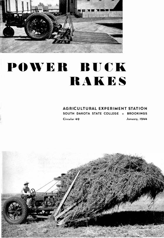
POWER BUCK
RAKES
AGRICULTURAL EXPERIMENT STATION
SOUTH DAKOTA STATE COLLEGE ,:, BROOKINGS
Circular 49 January, 1944

Cover Pictures
FRONT-MOUNTED BUCKER. When a bucker is mounted on
the front of a tractor and used for heavy duty, extra wheels should be
provided to carry the load. This bucker is carrying nearly a ton of hay.
The advantages of the front-mounte.d bucker are the greater
speed obtainable in loading because the regular forward gears are
used, and the convenience of operating the tractor in the usual way.
REAR-MOUNTED BUCKER. Rear mounting has the advantage
of putting the load on the drive wheels so that there is no danger of
overloading the front wheels, as there is with the front-mounted
bucker. It also minimizes tooth breakage by reducing the side motion
of the bucker during loading.
Another advantage is that this type of bucker is easy to control on
hillsides and on sandy soil. Over rough ground, large drive wheels
carry loads better than do small front wheels. Moreover, it is a simple
integral unit which is easily attached to the tractor.
Since this type of bucker must be loaded in reverse gear, its great
est disadvantage is the slow reverse speed obtainable with many trac
tors. However, the tractor can be operated in a forward gear after
loading. (For close-up of rear-mounted bucker, see Fig. 5.)
The author wishes to express his appreciation for helpful material furnished in the publications listed on the back of this circular and for drawings published by Ohio State University. Figs. 3, 10, and 11 are modifications of these drawings.
NOTE: There are no additional blueprints or other plans available from this Station than those shown in this Circular.

By L. F. LARSEN, Assistant Agricultural Engineer
For many years the buck rake, also known as the sweep rake, bull rake, hay buck, and hay sweep, has been one of the farmer's main tools for hay making. Originally horses pulled it but tractors are now widely used. Old cars are also converted into buckers. The early types of buckers were usually made to carry light loads since they were mainly intended to move hay the short distance from the windrow to a stacker. These types are illustrated in Figs. 1, 2, and 4.
In more recent years buckers have increased in usefulness because with motor power they can haul much larger loads, travel faster, and make longer hauls. When a heavy-duty bucker is mounted on the front of a tractor as shown on the cover page, extra wheels should be provided to carry the load. Otherwise wheels, tires, or bearings may be damaged when the bucker is traveling over rough ground with heavy loads.
Instructions given here on how to build buckers are general rather than specific because readers will probably find it necessary to adapt these plans to meet their own particular needs.
Uses for heavy-duty buckers. With these buckers it is possible to move hay directly from the field to the farmstead efficiently and economically. The auto bucker has been found to be the most economical method of moving hay to the farmstead (see table on page 4). The total cost per ton of moving hay with the auto bucker was $1.03. The second lowest cost was $1.37 per ton with the tractor buck rake.
Hay moved directly to the mow on buckers may be raised into the barn lofts by means of slings or grapple forks, or rolled onto stacks in feed lots by means of ropes. Because of the larger size and capacity of heavy-duty buckers, they are not so well adapted for use with a stacker as are the smaller buckers.
In addition to hauling hay, the heavy-duty buckers are rapidly becoming popular with threshing crews for hauling bundles of grain to the threshing machine. One good bucker can replace about three racks. When a bucker is used, it is well to have one man stay in the field to gather up missed bundles.
A third use for these large buckers is to haul shocked corn ancl other shocked roughage from the field to the farmstead.
3
4
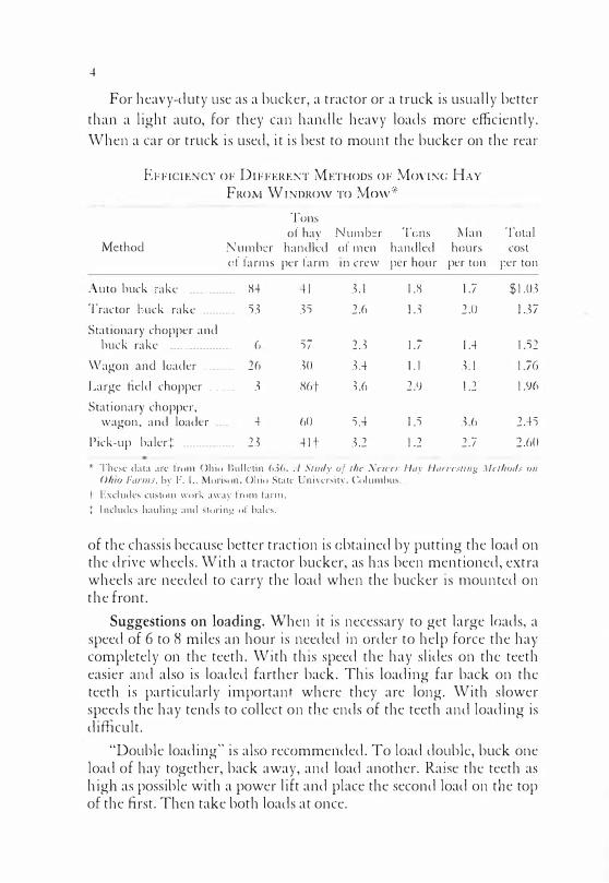
For heavy-duty use as a bucker, a tractor or a truck is usually better
than a light auto, for they can handle heavy loads more efficiently.
When a car or truck is used, it is best to mount the bucker on the rear
EFFICIENCY OF DIFFERENT METHODS OF MOVING HAY
FROM WINDROW To Mow'''
Method l\' u 111 ber cf fa rm s
Auto buck rake - --------------
Tractor buck rake ----------
Stationary chopper and buck rake
'v\lagon and
Large field
---- ·--------------
loader
chopper
-- -----·--
- - ----
Stationary chopper, wagon, and loader ----
Pick-up baler:/: ----------------
8-+ 53
6
26
3
-+
23
Tons of hay Numb�r Tens
handled of men h:rndled per farm 111 crew per hour
-+L 3.1 1.8 o-.)) 2.6 1.3
57 2.3 J.7
30 3.4 I.I
86r H 2.9
60 5.-+ 1.5
-+Ir 3.2 1.2
Man hours
per ton
J.7
2.0
I.-+ 3.1
! .2
3.6
2.7
Total cost
i:;er ton
$1.03
1.37
1.52
1.76
1.96
2.-+5
2.60
1= Thc!'-e data :He from Ohiu Bullt:tin 636. A Study of tht' Ncwf'r J--/ay 1-lon·c.•ting .\lcthorl.i un Ohio Farms ? b�· F. L. fvluri:-.on, Ohio State Uni\'crsit�·, Columhu:-..
J· Excludes cust11m work away from farm.
:;. Includes h:1uling :111d :-.t"oring· of b:1ks.
of the chassis because better traction is obtained by putting the load on the drive wheels. With a tractor bucker, as has been mentioned, extra wheels are needed to carry the load when the bucker is mounted on the front.
Suggestions on loading. '\Vhen it is necessary to get large loads, a speed of 6 to 8 miles an hour is needed in order to help force the hay completely on the teeth. With this speed the hay slides on the teeth easier and also is loaded farther back. This loading far back on the teeth is particularly important where they are long. With slower speeds the hay tends to collect on the ends of the teeth and loading is difficult.
"Double loading" is also recommended. To load double, buck one load of hay together, back away, and load another. Raise the teeth as high as possible with a power lift and place the second load on the top of the first. Then take both loads at once.

Front-Mounted anti Rear-Mounted Buekers
5
Fig. 1. Simple type of small buck rake for moving hay to the stacker. Such a bucker can easily be made and mounted on a car, pickup, truck, or tractor. To lift the teeth the driver pulls the rope. It is easy to mount a hand winch or an ordinary wire stretcher near the driver for him to use in winding up the rope.
-'
Fig. 2. Horse-type bucker converted for tractor use. This bucker is also suitable for such light-duty work as moving hay to the stacker. The bucker teeth are 9 feet long and the frame is 12 feet wide. For horsetype bucker mounted on the rear of a tractor, see Fig. 5.

6
MOTOR SHOULD BE E O UI PPE O WITH AN
AIR CLEANER
IF SHAFT IS EXPOSED PROVIDE A SHIELD
POWER IS SUPPLIED BY T.HE FAN BELT OR BY A SPECIAL PULLEY MOUNTED JUST IN FRONT OF THE FAN
V BELT PULL!!_... r--------
I
I I I I I I I ' I I I
MOTOR
: .., I
'-------- I
-AUTOMOBILE TRAN SMISSION
GEAR SHIFT CONTROL
FOR SAFETY ------1 ,----......_
LOADING BRACKET
IF AUTO HAD OPEN DRIVE SHAFT A CHAIN DRIVE COULD EASILY BE ATTACHED TO DRIVE REAR AXLE LIFTING DEVICE
PULLEY
r-------, I ' I I
: SEAT I I I �------- I
l�---��------1--�CONTROL LEVER
WOOD BEARING
Fig. 3. How to attach a power lift to a used auto. A rake similar to the one shown in Fig. 10 can be mounted on the rear of the auto frame. For power lift, see Fig. 12.

7
Fig. 4. Auto chassis bucker. Hand lever is used for raising the teeth. The rear axle was inverted so that the auto would travel backward when driven by the reguiar forward gears. The front axle was reversed to retain good steering qualities. Some operators leave the rear axle and front axle as they are and load in reverse gear. After loading, the teeth are raised and the auto driven forward. This plan is especially desirable when a power lift is used and where long hauls are necessary.
Fig. 5. A horse-type bucker remodeled at the South Dakota Station to mount on the rear of a tractor with a power lift. It is important to have the rear end of the teeth as near the rear wheels as possible. For advantages of rear mounting, see page 2. Many farmers have changed their tractors to make possible more speedy reverse travel.

Fig. 6. (Above) Power lift arrangement for the rear-mount(d bucker.
Below the old automobile axle is the support pipe "S," a 1 �-inch pipe welded to the push arms. They in turn are chained up to the lift frame
at the proper height. Fig. 7 (Below) Slight change made in a horse
type bucker for mounting on the rear of a tractor. The 1-inch pipe passing through the 4"x6" hinge arms also passes through the pipe "S,"
shown in Fig. 6.

C=>
C=>
SIDE VIEW OF BUCKER
r
2")( 6"
- ---10'
4")(6"
HI\NO LIFT COULD EASILY BE ARRANGED AS A SUBSTITUTE FOR POWER LIFT
'-1======================-J
�
J _
BRAKE CONTROL LEVER-.
MOUNTING OF POWER LIFT AND BUCKER SUPPORT
1/4� X z",c z• ANGLE
DRILL 1-\0LESTO FIT CULTtVATM BRACKETS r-
WELD REAR AXLE TO ANGLE
<
1/4" PLATE WELDED
. ..,'wELD SUPPORT PERMITS BUCKER FRAME TO RISE lf
NECESSARY
,:.•� ,-4")( 6"
BUCKER FRAME
BUCKER SUPPORT BRACKET
ALLMETAL � 3/8° 1i3"X 3"8AR_
,,:· � 0 . :· t�� � •
fO,O Vl[W l WELD- fl--WELD
j !; o I !44"x 6"'euCKER
£ '' FRAME ilDt VI[': - USE 518" BOLTS
FRONT HITCH CONSTRUCTION
Fig. 8. This bucker, designed at the South Dakota Station, is sturdier than the rear-mounted bucker on the cover and can operate the large rake in Fig. 10. '°
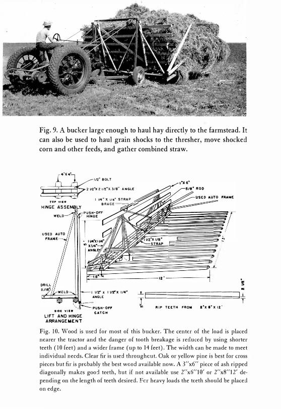
Fig. 9. A bucker large enough to haul hay directly to the farmstead. It
can also be used to haul grain shocks to the thresher, move shocked
corn and other feeds, and gather combined straw.
4"X4l
�:::.�,,.- '""' . I V4" X 1/4" STRAP TOf' VICW
BRACE-----:,�r HINGE ASSEMBLY
.. IOI '11 IW
LIFT ANO HINGE
ARRANGEMENT
1 112" • 1 vrx 114•
ANGLE
PU�H-0"
CATCH
L E
! '!: ..
....LE===�;;;�;:;;;;;:;:J.1.
1 RIP TEETH FRON 1'x1·x11··
T
Fig. 10. Wood is used for most of this bucker. The center of the load is placed
nearer the tractor and the danger of tooth breakage is reduced by using shorter
teeth (10 feet) and a wider frame (up to 14 feet). The width can be made to meet
individual needs. Clear fir is used throughout. Oak or yellow pine is best for cross
pieces but fir is probably the best wood available now. A 3"x6" piece of ash ripped
diagonally makes goo:! teeth, hut if not available use 2"x6"10' or 2"x8"12' de
pending on the length of teeth desired. Fer heavy loads the te·eth should be placed
on edge.

% "' I- ai: 0 "' i %
ai: ai: "' "' � � (.) (.) ::, ::, ID ID N ..... )( 0 er Q. 0.. Cl
J __ [ _\1 . . �
--=::! _ .....,.
/ -- - - - - - - - -- - - - - - - - - - - -- --,,USED DISK ( '�LDED ON I I P I PE
CABLE OR ROPE ' I ' , --------- - --- ------------/ AXLE
ROD 3" P I PE 9" LONG WELDED TO H U B A UTO FRAME
RAI SED SUPPORT FOR GUIDE BAR . THI S IS NEE DED TO K E E P BUCKE R C ENTE R ED WHEN B A C K I N G
2 lfl"X 2 ll't' X 114" A N G LE I R ON W E LDED TO AXLE S U P P O RTS
ATTA C H TO OULTIVATOR B RA C K E T S
WOOD B E ARING TO H O L D 3/4" C O N T R O L P I P E _ . _
... -- - - ----- - - - - - - - ------, '
c "' en :::>
-::::i.....---1... __ ----"\--'- MAKE STEERING ADJUSTMENTS
I '
I I
AVAIL.ABLE H E R E I I \ I ' , -- - - - - - -- - - - - - - - - --------/
Fig. 1 1 . Construction of the carrier frame for buckers in Figs. 9 and 10 and the front-mounted bucker on the cover. For power lift, see Fig. 12. =
12
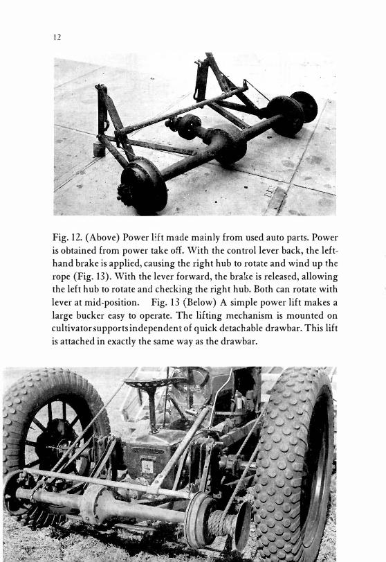
Fig. 12. (Above) Power lift made mainly from used auto parts. Power
is obtained from power take off. With the control lever back, the lefthand brake is applied, causing the right hub to rotate and wind up the
rope (Fig. 13). With the lever forward, the brake is released, allowing the left hub to rotate and checking the right hub. Both can rotate with
lever at mid-position. Fig. 1 3 (Below) A simple power lift makes a
large bucker easy to operate. The lifting mechanism is mounted on cultivator supports independent of quick detachable drawbar. This lift
is attached in exactly the same way as the drawbar.

Fig. 14. (Above) Bucker constructed from lumber and old auto frames. This material is generally available to farmers and many will have it in their own shops. A large type of bucker such as this will be subjected to severe usage and strong diagonal bracing is important. Fig. 15. (Below) Suggested arrangement of brace bar and drag link. The brace bar is needed when backing in order to keep the bucker wheels in line with the front wheels of the tractor. When driving forward the brace bar is not needed as the bucker wheels and tractor wheels can easily be made to work together.
14
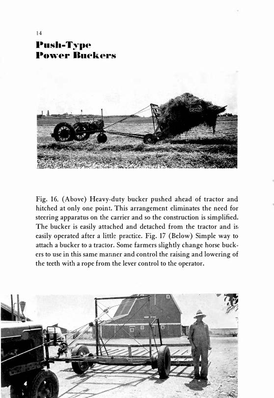
Push-Type Po,ver Bncke•·s
Fig. 16. (Above) Heavy-duty bucker pushed ahead of tractor and. hitched at only one point. This arrangement eliminates the need for steering apparatus on the carrier and so the construction is simplified.
The bucker is easily attached and detached from the tractor and is,
easily operated after a little practice. Fig. 17 (Below) Simple way to attach a bucker to a tractor. Some farmers slightly change horse buck
ers to use in this same manner and control the raising and lowering of the teeth with a rope from the lever control to the operator .
... ,. < . '')
f!U �
I
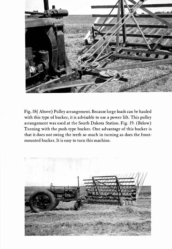
Fig. 18( Above) Pulley arrangement. Because large loads can be hauled
with this type of bucker, it is advisable to use a power lift. This pulley
arrangement was used at the South Dakota Station. Fig. 19. (Below)
Turning with the push-type bucker. One advantage of this bucker is
that it does not swing the teeth so much in turning as does the front
mounted bucker. It is easy to turn this machine.

-r-; I !! ... .. " ... �
:c
"' g ... .. � " � :c
L 1 2 '------- ---/' - ---.. \ USED DISK
LENGTHENfD
BE
2 1rl" X 2 112"X 3/8" A N G L E I RON SUPPORT �OR PULLEYS ---- ·� ANGLE
: J WEL0£D TO
\,. __ _ _ _ _ _ _ - - - - _ _ _ _ _ _ _ _ ___ .,/' rPIPE
I l/2"X I l/2"X 1/4" ANGLE
CONTROL LEVER I l/4" X I l/4"X 1/8,. ANGLE
IIION WELDED TO PIPE ----....,.
TRACTOR FRAME
IRON WELDED TO AUTO AXLE SUPPORT. ATTACH THESE TO GULTIYATOR BRACKETS .- - -· ---{L;,C,:::".'" }�Ai
I
WOOD BEARINGS FOR CONTROL
_,---""=""a,::::=""- 3/B"X 2 1/2" STRAP
AUTO FRAME----WELDED TO AUTO FRAME
SIDE VIEW OF HITCH (, .. ·-- ------- - - - - - --.' �', .. __ ----
------ -- ----- - ______ .. ;'
Fig. 20. Suggested arrangement for power lift and hitch assembly for the push-type power bucker. For details of power lift, see Fig. 12. Some farmers have made good use of this hitch
arrangement and wheels as a 2-wheel trailer when it was not used as a bucker.
O'

17
Stacker-Buckers
Many requests have been received at the South Dakota Station for
information regarding plans for a stacker-bucker combination. Dur
ing the summer of 1 943 a simple stacker-bucker was constructed and
used at this Station.
The machine built here worked quite satisfactori ly for an init ial
trial and with minor ad justments i t can be developed into a very satis-
Fig. 21 . Overshot stacker-bucker unloading hay near Brookings. It was
made mainly out of lumber. Clear fir was used throughout.
factory home-made stacker-bucker. 1 Only one complete stack of hay
was buil t with i t owing to the lateness in the season. Although the pull
on the ropes in starting to raise the load up onto the stack is made at a
d isadvantage, the tractor seemed to have no d ifficulty in starting it . In
tentions were to place a pair of brackets on the frame with pulleys in
order to increase the mechanical advantage in starting to raise the load,
but with the power available these brackets were not necessary.
I The author h:1s left this Station and work on this machine has been c l i sco nl i nued for the present.

1 8
Fig. 22. Stacker fork is pulled forward and over center by engaging power lift for an instant.
Fig. 23. Lifting power is provided by windlass driven by chain from the same rear-axle assembly as shown in Fig. 12.

Fig. 24. Brace bar and steering linkage for the stacker-bucker.
HOW IT WORKS
These three pictures show how the stackerbucker works. When the brake is slipped, the fork (Fig. 22) is lowered. The teeth shown here are 9 feet long and the cross pieces are 12 feet long.
The windlass shown in Fig. 23 should be at least 5 inches in diameter. Hinge point of stacker arms can be raised 2 feet when higher lift is desired. The rear part of the stacker-bucker is supported by only two large bolts so it can be easily unhooked from the tractor.
The brace bar pictured above is needed in order to keep the wheels of the tractor and the stacker-bucker coordinated when backmg.
19

Fig. 25. Loading hay on rack with a stacker-bucker. Extra front wheels carry most of the weight of the stacker-bucker and hay, eliminating any danger of damaging front-end assembly of tractor. For these wheels, rubber-tired auto wheels are much better than those shown above. Steering plans are like those in Fig. 1 1.
More Information on Buckers The following publications can be obtained from the sources given.
Buck Rakes ( Bullet in) by C. B. Richey and R. D. Barden, Ohio State University, Columbus.
Effective Haying Equipment and Practices ( U.S.D.A. Farmers' Bulletin No. 1525).
Homemade Auto Buck Rake (C ircular 172) by 0. W. Monson, Montana State College, Bozeman.
Homemade Farm Equipment ( Bulletin 443) by William P. Kintzley, Colorado Experiment Station, Fort Collins.
Homemade Sweep for Tricycle-Type Tractor (Mimeographed Sheet-Information Series 4) by Carlton L. Zink, University of Tebraska, Lincoln.
Su;eep Rakes ( Mimeographed Extension Circular) by R. C. Shipman, Purdue University, Lafayette, Indiana.
Transport Buck Rake ( Circular) by C. E. Barbee and C. Loienzen, Jr., University of California, Berkeley 4.
Transport Su;eep Rake (Mimeographed Circular) published by Michigan State College, East Lansing.
Agriculture Extension Service-Plan Sheet M-109 ( contains in formation on sweep rakes) by John Strait and Norton Ives, University of Minnesota, St. Paul.
IO�·I-J .44-6108
3 .5�1-5-44- 62 1 5