Datalink Layer
14
Advanced Communication Networks Chapter 5 ISDN Data Link Layer The University of Sydney AUSTRALIA School of Electrical and Information Engineering Abbas Jamalipour Based on chapter 8 of Stallings ISDN-4e book
-
Upload
harshit-marwah -
Category
Documents
-
view
11 -
download
0
description
DVC DATA LINK
Transcript of Datalink Layer

Advanced CommunicationNetworks
Chapter 5
ISDN Data Link Layer
The University of Sydney AUSTRALIA
School of Electrical and Information Engineering
Abbas Jamalipour
Based on chapter 8 of Stallings ISDN-4e book

ISDN Data Link Layer 2
5.1 Link Access Protocol–D Channel
• All traffic over D channel uses LAPD defined in Q.921.
• LAPD service will support– multiple terminals at the user-network installation
– multiple layer 3 entities (e.g., X.25 level 3, Q.931)
• Two types of service to LAPD users by LAPD standard– unacknowledged information-transfer service
– acknowledged information-transfer service
unacknowledged information-transfer service
• does not guarantee delivery of data nor inform of failure
• no flow control, no error control mechanism
• supports both point-to-point and broadcast
• fast data transfer, e.g. management procedures (alarm messages)
acknowledged information-transfer service
• more common, similar to service of LAPB and HDLC
• three phases of connection establishment between two users– connection establishment
– data transfer
– connection termination
• guarantee of frame delivery in the order of transmission
Two types of LAPD operation corresponding to two types of service
• unacknowledged operation: layer 3 information is transferredin unnumbered frames, error detection, no error or flow control
• acknowledged operation: layer 3 information is transferred inframes with sequence numbers and acknowledged, with errorand flow control, also referred to as multiple-frame operation
two types of operation may coexist on a single D channel

ISDN Data Link Layer 3
Frame Structure
Flag Fields• a unique pattern of 01111110 to delimit the frame at both ends
• using bit stuffing to allows the presence of arbitrary patterns
data transparency property
Structure of the LAPD frames

ISDN Data Link Layer 4
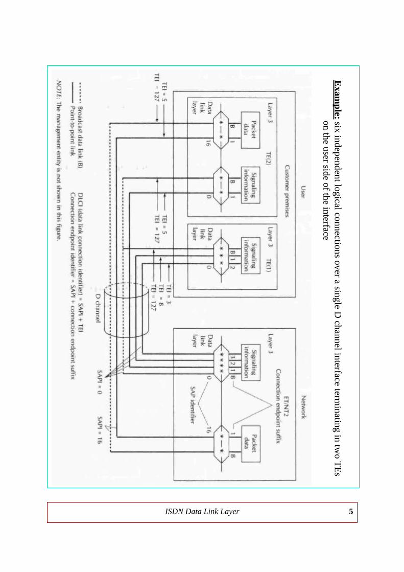
Address Field• a two-part address for dealing with two levels of multiplexing
– multiple user devices sharing the same physical interface
– multiple types of traffic within each user device (PS data and cont.)
* Terminal endpoint identifier (TEI)– given to each user device manually or automatically
* Service access point identifier (SAPI)– corresponds to a layer 3 protocol entity within a user device
• SAPI values are unique within a TEI
• SAPI and TEI together identify a logical connection → DLCI
• at any time, LAPD may maintain multiple logical connection,each with a unique DLCI → one log. connec. per a layer 3 entity
• Command/response (C/R) bit shows the type of LAPD messageSAPI and TEI assignments
ISDN Data Link Layer 5
Exam
ple: six independent logical connections over a single D channel interface term
inating in two T
Es
on the user side of the interface

ISDN Data Link Layer 6
Control Field• three types of frames and three different control field
– Information-transfer frames (I-frames)• carrying data to be transmitted for user
• piggybacked of flow- and error-control data using go-back-N ARQ
– Supervisory frames (S-frames)• providing ARQ mechanism
– Unnumbered frames (U-frames)• providing supplemental link-control functions
• supporting unacknowledged operation
• poll/final (P/F) bit– P=1: solicit a response frame from the peer LAPD entity
– F=1 in response frame indicating the response frame transmission
Information Field• presents only in I-frames and some unnumbered frames
• max length of information field specified in Q.921=260 bytes
Frame-Check Sequence Field• an error-detecting code for all field except flags using CRC
Three phases in acknowledged operation
• Connection Establishment– requested by either network or subscriber by sending a SABME (Set
Asynchronous Balanced Mode Extended) frame (used in HDLC)
– SABME contains TEI and SAPI of the layer 3 of requested entity
– replied by a UA or DM frame to confirm or reject the request
• Data Transfer– sending I-frames with N(S) and N(R) fields in modulo 128
– flow- and error-control, sliding window FC and go-back-N ARQ EC
• Disconnect– by sending a DISC frame which replied by a UA frame

ISDN Data Link Layer 7
Frame-Reject Frame (FRMR)
• indicating an improper frame reception because of– receipt of an undefined or not implemented control field
– receipt of an S-frame or U-frame with incorrect length
– receipt of an invalid N(R)
– receipt of an I-frame with a too long information field
• The FRMR effect is to abort the connection.
LAPD commands and responses

ISDN Data Link Layer 8
Example of LAPD acknowledged operation

ISDN Data Link Layer 9
5.2 Terminal Adaption
• During transition period, existing ISDN-incompatible datacommunication devices can use a terminal adapter (TA).
• TA function id to map a non-ISDN terminal to an ISDN interface.
• Functions that performed in this mapping are:– Rate adaption: mapping low data stream into 64 kbps
– Signaling conversion: mapping signaling protocol into Q.931
– X.25 conversion: converting functions of non-ISDN X.25 devices to operate onthe B and/or D channels
– Physical interface conversion: mapping non-ISDN interface onto ISDN’s twptwisted pairs at the S or T interface
– Digitization: analog-to-digital conversion for analog devicesSummary of TA procedures
Comparison of TA standards
ISDN Data Link Layer 10
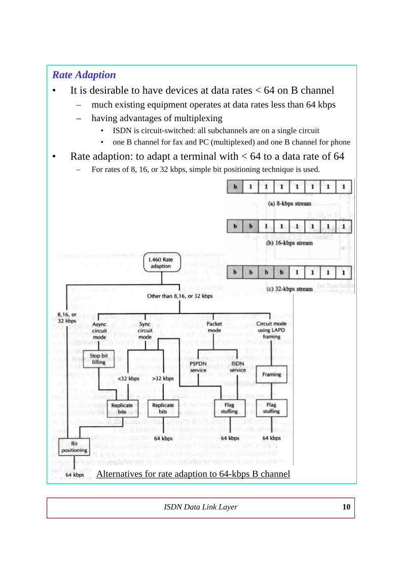
Rate Adaption
• It is desirable to have devices at data rates < 64 on B channel– much existing equipment operates at data rates less than 64 kbps
– having advantages of multiplexing• ISDN is circuit-switched: all subchannels are on a single circuit
• one B channel for fax and PC (multiplexed) and one B channel for phone
• Rate adaption: to adapt a terminal with < 64 to a data rate of 64– For rates of 8, 16, or 32 kbps, simple bit positioning technique is used.
Alternatives for rate adaption to 64-kbps B channel

ISDN Data Link Layer 11
Rate adaption for rates other than 8, 16, or 32 kbps
• Synchronous circuit-mode devices– For rates < 32 kbps, a two-stage adaption function is used.
– The user data rate is first converted to an intermediate rate of 8, 16,or 32 kbps, then in second stage (RA2) bit positioning method used.
– In circuit-switching rate adaption, the two subscriber operate at thesame data rate (which is identified during call setup).
Rate adptionI.463/V.110
Adaption of 2400-bps user rate to 8-kcs intermediate rate

ISDN Data Link Layer 12
• Asynchronous circuit-mode devices– For handling asynchronous devices, a three stage method is used.
– In first stage (RA0) asynchronous stream converts to sync data rate.
– The technique is to add additional stop bits between characters tostep up data rate to the nearest intermediate rate acceptable by RA1.
• Packet-mode support– support of packet-mode equipment over ISDN operated < 64 kbps
– LAPB frames accepted from subscriber and buffered in TA.
– Each frame is then transmitted onto the B channel at 64 kbps withgaps being filled with flag (01111110): interframe flag stuffing
– Two-stage rate adaption is also possible but it is less flexible.
• Circuit-mode support using LAPD framing– An alternative method of supporting synchronous circuit-mode
equipment is to encapsulate the incoming synchronous bit streaminto LAPD frames and then adapted to 64 kbps by flag stuffing.
– The advantage of this method compared to the previously discussedmethod is that the data are transmitted now using a data link controlprotocol which provides for the benefits of flow and error controlthat are inherent in a link-control protocol.
Multiplexing
• combining traffic from multiple <64 terminals onto a 64 B ch.
• For data rate of 8, 16, or 32 kbps, bits from different streams, upto a total of 64 kbps, are interleaved within each octet.
– fixed-format multiplexing• bit positions are fixed according to the data rate of incoming stream
• the 64-kbps capacity may not be utilized effectively
– flexible-format multiplexing• first, subrate stream using fixed-format procedure is attempted.
• If it fails, subrate stream is added by inserting each successive bit of thenew stream into the earliest available bit position in the B channel octet.
• always allows sbrate streams to be multiplexed up to the 64 limit
– Both methods are examples of synchronous TDM

ISDN Data Link Layer 13
Multiplexing for rates other than 8, 16, or 32 kbps
• Circuit-mode devices– A two-stage approach is used:
• First, each stream is rate adapted to 8, 16, or 32 kbps.
• Second, the resulting streams are multiplexed.
• Packet-mode support– multiplexing function is provided by layer 3 VC mechanism of X.25
– once a connection is made via a B or D ch. to a packet-switchingnode, multipe VCs cab be set up across that connection.
• Circuit-mode support using LAPD framing– using the 13-bit logical link identifier (LLI) field of LAPD frame
– with LLI, user can simultaneously establish multiple logical linksover a single B channel circuit.
– LLI enables recipient to sort out the incoming traffic and to route it.

ISDN Data Link Layer 14
5.3 Bearer Channel Data Link Control
• I.465/V.120 provides a technique for supporting non-ISDN terminals overa B channel using a data link protocol that is a modified form of LAPD.
– Asynchronous protocol sensitive
– HDLC synchronous protocol sensitive
– Bit transparent
• I.465/V.120 provides a flexible and useful data link protocol for B ch.
• V.120 standard may be used in circuit-switching or frame relay– Over either circuit-mode or frame-mode connections
– Using either demand or semipermanent establishment of communications
– Over any of the following types of access channel:• for circuit-mode connections: D, Ho, H10, or H11
• for frame-mode connections: B, H0, H10, or H11, or D
different types of data stream carried by I.465/V.120
←← operation
Types of I.465/V.120 TE connections