5: DataLink Layer5-1 Chapter 5 Link Layer and LANs.
75
5: DataLink Layer 5-1 Chapter 5 Link Layer and LANs
-
Upload
franklin-greene -
Category
Documents
-
view
238 -
download
0
Transcript of 5: DataLink Layer5-1 Chapter 5 Link Layer and LANs.

5 DataLink Layer 5-1
Chapter 5Link Layer and LANs
5 DataLink Layer 5-2
Chapter 5 The Data Link LayerOur goals understand principles behind data link layer
services error detection correction sharing a broadcast channel multiple access link layer addressing reliable data transfer flow control done
instantiation and implementation of various link layer technologies
5 DataLink Layer 5-3
Link Layer
51 Introduction and services
52 Error detection and correction
53Multiple access protocols
54 Link-layer Addressing
55 Ethernet
56 Link-layer switches 57 PPP
5 DataLink Layer 5-4
Link Layer IntroductionSome terminology hosts and routers are nodes communication channels
that connect adjacent nodes along communication path are links wired links wireless links LANs
layer-2 packet is a frame encapsulates datagram
data-link layer has responsibility of transferring datagram from one node to adjacent node over a link
5 DataLink Layer 5-5
Link layer context
datagram transferred by different link protocols over different links eg Ethernet on first
link frame relay on intermediate links 80211 on last link
each link protocol provides different services eg may or may not
provide rdt over link
transportation analogy trip from Princeton to
Lausanne limo Princeton to JFK plane JFK to Geneva train Geneva to Lausanne
tourist = datagram transport segment =
communication link transportation mode =
link layer protocol travel agent = routing
algorithm
5 DataLink Layer 5-6
Link Layer Services framing link access
encapsulate datagram into frame adding header trailer
channel access if shared medium ldquoMACrdquo addresses used in frame headers to identify
source dest bull different from IP address
reliable delivery between adjacent nodes we learned how to do this already (chapter 3) seldom used on low bit-error link (fiber some twisted
pair) wireless links high error rates
bull Q why both link-level and end-end reliability
5 DataLink Layer 5-7
Link Layer Services (more)
flow control pacing between adjacent sending and receiving nodes
error detection errors caused by signal attenuation noise receiver detects presence of errors
bull signals sender for retransmission or drops frame
error correction receiver identifies and corrects bit error(s) without
resorting to retransmission
half-duplex and full-duplex with half duplex nodes at both ends of link can
transmit but not at same time
5 DataLink Layer 5-8
Where is the link layer implemented
in each and every host link layer implemented in
ldquoadaptorrdquo (aka network interface card NIC) Ethernet card PCMCI card
80211 card implements link physical
layer
attaches into hostrsquos system buses
combination of hardware software firmware
controller
physicaltransmission
cpu memory
host bus (eg PCI)
network adaptercard
host schematic
applicationtransportnetwork
link
linkphysical
5 DataLink Layer 5-9
Adaptors Communicating
sending side encapsulates datagram
in frame adds error checking bits
rdt flow control etc
receiving side looks for errors rdt flow
control etc extracts datagram passes
to upper layer at receiving side
controller controller
sending host receiving host
datagram datagram
datagram
frame
5 DataLink Layer 5-10
Link Layer
51 Introduction and services
52 Error detection and correction
53Multiple access protocols
54 Link-layer Addressing
55 Ethernet
56 Link-layer switches 57 PPP
5 DataLink Layer 5-11
Error DetectionEDC= Error Detection and Correction bits (redundancy)D = Data protected by error checking may include header fields
bull Error detection not 100 reliablebull protocol may miss some errors but rarelybull larger EDC field yields better detection and correction
otherwise
5 DataLink Layer 5-12
Parity Checking
Single Bit ParityDetect single bit errors
Two Dimensional Bit ParityDetect and correct single bit errors
0 0
5 DataLink Layer 5-13
Internet checksum (review)
Sender treat segment contents
as sequence of 16-bit integers
checksum addition (1rsquos complement sum) of segment contents
sender puts checksum value into UDP checksum field
Receiver compute checksum of
received segment check if computed
checksum equals checksum field value NO - error detected YES - no error detected
But maybe errors nonetheless
Goal detect ldquoerrorsrdquo (eg flipped bits) in transmitted packet (note used at transport layer only)
5 DataLink Layer 5-14
Checksumming Cyclic Redundancy Check view data bits D as a binary number choose r+1 bit pattern (generator) G goal choose r CRC bits R such that
ltDRgt exactly divisible by G (modulo 2) receiver knows G divides ltDRgt by G If non-zero
remainder error detected can detect all burst errors less than r+1 bits
widely used in practice (Ethernet 80211 WiFi ATM)
5 DataLink Layer 5-15
CRC ExampleWant
D2r XOR R = nGequivalently
D2r = nG XOR R equivalently if we divide D2r by
G want remainder R
R = remainder[ ]D2r
G
5 DataLink Layer 5-16
Link Layer
51 Introduction and services
52 Error detection and correction
53Multiple access protocols
54 Link-layer Addressing
55 Ethernet
56 Link-layer switches 57 PPP
5 DataLink Layer 5-17
Multiple Access Links and Protocols
Two types of ldquolinksrdquo point-to-point
PPP for dial-up access point-to-point link between Ethernet switch and host
broadcast (shared wire or medium) old-fashioned Ethernet upstream HFC 80211 wireless LAN
shared wire (eg cabled Ethernet)
shared RF (eg 80211 WiFi)
shared RF(satellite)
humans at acocktail party
(shared air acoustical)
5 DataLink Layer 5-18
Multiple Access protocols single shared broadcast channel two or more simultaneous transmissions by nodes
interference collision if node receives two or more signals at the same
time
multiple access protocol distributed algorithm that determines how nodes
share channel ie determine when node can transmit
communication about channel sharing must use channel itself no out-of-band channel for coordination
5 DataLink Layer 5-19
Ideal Multiple Access Protocol
Broadcast channel of rate R bps1 when one node wants to transmit it can send
at rate R2 when M nodes want to transmit each can
send at average rate RM3 fully decentralized
no special node to coordinate transmissions no synchronization of clocks slots
4 simple
5 DataLink Layer 5-20
MAC Protocols a taxonomy
Three broad classes Channel Partitioning
divide channel into smaller ldquopiecesrdquo (time slots frequency code)
allocate piece to node for exclusive use
Random Access channel not divided allow collisions ldquorecoverrdquo from collisions
ldquoTaking turnsrdquo nodes take turns but nodes with more to send can
take longer turns
5 DataLink Layer 5-21
Channel Partitioning MAC protocols TDMA
TDMA time division multiple access access to channel in rounds each station gets fixed length slot (length =
pkt trans time) in each round unused slots go idle example 6-station LAN 134 have pkt slots
256 idle
1 3 4 1 3 4
6-slotframe
5 DataLink Layer 5-22
Channel Partitioning MAC protocols FDMA
FDMA frequency division multiple access channel spectrum divided into frequency bands each station assigned fixed frequency band unused transmission time in frequency bands go
idle example 6-station LAN 134 have pkt
frequency bands 256 idle fr
equ
ency
bands time
FDM cable
5 DataLink Layer 5-23
Random Access Protocols
When node has packet to send transmit at full channel data rate R no a priori coordination among nodes
two or more transmitting nodes ldquocollisionrdquo random access MAC protocol specifies
how to detect collisions how to recover from collisions (eg via delayed
retransmissions)
Examples of random access MAC protocols slotted ALOHA ALOHA CSMA CSMACD CSMACA
5 DataLink Layer 5-24
Slotted ALOHA
Assumptions all frames same size time divided into
equal size slots (time to transmit 1 frame)
nodes start to transmit only slot beginning
nodes are synchronized
if 2 or more nodes transmit in slot all nodes detect collision
Operation when node obtains fresh
frame transmits in next slot if no collision node
can send new frame in next slot
if collision node retransmits frame in each subsequent slot with prob p until success
5 DataLink Layer 5-25
Slotted ALOHA
Pros single active node can
continuously transmit at full rate of channel
highly decentralized only slots in nodes need to be in sync
simple
Cons collisions wasting
slots idle slots nodes may be able to
detect collision in less than time to transmit packet
clock synchronization
5 DataLink Layer 5-26
Slotted Aloha efficiency
suppose N nodes with many frames to send each transmits in slot with probability p
prob that given node has success in a slot = p(1-p)N-1
prob that any node has a success = Np(1-p)N-1
max efficiency find p that maximizes Np(1-p)N-1
for many nodes take limit of Np(1-p)N-1
as N goes to infinity gives
Max efficiency = 1e = 37
Efficiency long-run fraction of successful slots (many nodes all with many frames to send)
At best channelused for useful transmissions 37of time
5 DataLink Layer 5-27
Pure (unslotted) ALOHA unslotted Aloha simpler no synchronization when frame first arrives
transmit immediately
collision probability increases frame sent at t0 collides with other frames sent in [t0-
1t0+1]
5 DataLink Layer 5-28
Pure Aloha efficiencyP(success by given node) = P(node transmits)
P(no other node transmits in [p0-1p0]
P(no other node transmits in [p0-1p0]
= p (1-p)N-1 (1-p)N-1
= p (1-p)2(N-1)
hellip choosing optimum p and then letting n -gt infty
= 1(2e) = 18
even worse than slotted Aloha
5 DataLink Layer 5-29
CSMA (Carrier Sense Multiple Access)
CSMA listen before transmitIf channel sensed idle transmit entire frame If channel sensed busy defer transmission
human analogy donrsquot interrupt others
5 DataLink Layer 5-30
CSMA collisions
collisions can still occurpropagation delay means two nodes may not heareach otherrsquos transmissioncollisionentire packet transmission time wasted
spatial layout of nodes
noterole of distance amp propagation delay in determining collision probability
5 DataLink Layer 5-31
CSMACD (Collision Detection)CSMACD carrier sensing deferral as in CSMA
collisions detected within short time colliding transmissions aborted reducing
channel wastage collision detection
easy in wired LANs measure signal strengths compare transmitted received signals
difficult in wireless LANs received signal strength overwhelmed by local transmission strength
human analogy the polite conversationalist
5 DataLink Layer 5-32
CSMACD collision detection
5 DataLink Layer 5-33
ldquoTaking Turnsrdquo MAC protocolschannel partitioning MAC protocols
share channel efficiently and fairly at high load
inefficient at low load delay in channel access 1N bandwidth allocated even if only 1 active node
Random access MAC protocols efficient at low load single node can fully
utilize channel high load collision overhead
ldquotaking turnsrdquo protocolslook for best of both worlds
5 DataLink Layer 5-34
ldquoTaking Turnsrdquo MAC protocolsPolling master node
ldquoinvitesrdquo slave nodes to transmit in turn
typically used with ldquodumbrdquo slave devices
concerns polling overhead latency single point of
failure (master)
master
slaves
poll
data
data
5 DataLink Layer 5-35
ldquoTaking Turnsrdquo MAC protocolsToken passing control token
passed from one node to next sequentially
token message concerns
token overhead latency single point of failure
(token)
T
data
(nothingto send)
T
5 DataLink Layer 5-36
Summary of MAC protocols
channel partitioning by time frequency or code Time Division Frequency Division
random access (dynamic) ALOHA S-ALOHA CSMA CSMACD carrier sensing easy in some technologies (wire)
hard in others (wireless) CSMACD used in Ethernet CSMACA used in 80211
taking turns polling from central site token passing Bluetooth FDDI IBM Token Ring
5 DataLink Layer 5-37
Link Layer
51 Introduction and services
52 Error detection and correction
53Multiple access protocols
54 Link-Layer Addressing
55 Ethernet
56 Link-layer switches 57 PPP
5 DataLink Layer 5-38
MAC Addresses and ARP
32-bit IP address network-layer address used to get datagram to destination IP subnet
MAC (or LAN or physical or Ethernet) address function get frame from one interface to
another physically-connected interface (same network)
48 bit MAC address (for most LANs)bull burned in NIC ROM also sometimes software
settable
5 DataLink Layer 5-39
LAN Addresses and ARPEach adapter on LAN has unique LAN address
Broadcast address =FF-FF-FF-FF-FF-FF
= adapter
1A-2F-BB-76-09-AD
58-23-D7-FA-20-B0
0C-C4-11-6F-E3-98
71-65-F7-2B-08-53
LAN(wired orwireless)
5 DataLink Layer 5-40
LAN Address (more)
MAC address allocation administered by IEEE manufacturer buys portion of MAC address
space (to assure uniqueness) analogy (a) MAC address like Social Security Number (b) IP address like postal address MAC flat address portability
can move LAN card from one LAN to another
IP hierarchical address NOT portable address depends on IP subnet to which node is
attached
5 DataLink Layer 5-41
ARP Address Resolution Protocol
Each IP node (host router) on LAN has ARP table
ARP table IPMAC address mappings for some LAN nodes
lt IP address MAC address TTLgt
TTL (Time To Live) time after which address mapping will be forgotten (typically 20 min)
Question how to determineMAC address of Bknowing Brsquos IP address
1A-2F-BB-76-09-AD
58-23-D7-FA-20-B0
0C-C4-11-6F-E3-98
71-65-F7-2B-08-53
LAN
137196723
137196778
137196714
137196788
5 DataLink Layer 5-42
ARP protocol Same LAN (network) A wants to send datagram
to B and Brsquos MAC address not in Arsquos ARP table
A broadcasts ARP query packet containing Bs IP address dest MAC address = FF-
FF-FF-FF-FF-FF all machines on LAN
receive ARP query B receives ARP packet
replies to A with its (Bs) MAC address frame sent to Arsquos MAC
address (unicast)
A caches (saves) IP-to-MAC address pair in its ARP table until information becomes old (times out) soft state information
that times out (goes away) unless refreshed
ARP is ldquoplug-and-playrdquo nodes create their ARP
tables without intervention from net administrator
5 DataLink Layer 5-43
Addressing routing to another LAN
R
1A-23-F9-CD-06-9B
222222222220111111111110
E6-E9-00-17-BB-4B
CC-49-DE-D0-AB-7D
111111111112
111111111111
A74-29-9C-E8-FF-55
222222222221
88-B2-2F-54-1A-0F
B222222222222
49-BD-D2-C7-56-2A
walkthrough send datagram from A to B via R assume A knows Brsquos IP address
two ARP tables in router R one for each IP network (LAN)
5 DataLink Layer 5-44
A creates IP datagram with source A destination B A uses ARP to get Rrsquos MAC address for 111111111110 A creates link-layer frame with Rs MAC address as dest
frame contains A-to-B IP datagram Arsquos NIC sends frame Rrsquos NIC receives frame R removes IP datagram from Ethernet frame sees its
destined to B R uses ARP to get Brsquos MAC address R creates frame containing A-to-B IP datagram sends to B
R
1A-23-F9-CD-06-9B
222222222220
111111111110
E6-E9-00-17-BB-4B
CC-49-DE-D0-AB-7D
111111111112
111111111111
A74-29-9C-E8-FF-55
222222222221
88-B2-2F-54-1A-0F
B222222222222
49-BD-D2-C7-56-2A
This is a really importantexample ndash make sure youunderstand
5 DataLink Layer 5-45
Link Layer
51 Introduction and services
52 Error detection and correction
53Multiple access protocols
54 Link-Layer Addressing
55 Ethernet
56 Link-layer switches 57 PPP
5 DataLink Layer 5-46
Ethernet
ldquodominantrdquo wired LAN technology cheap $20 for NIC first widely used LAN technology simpler cheaper than token LANs and ATM kept up with speed race 10 Mbps ndash 10 Gbps
Metcalfersquos Ethernetsketch
5 DataLink Layer 5-47
Star topology bus topology popular through mid 90s
all nodes in same collision domain (can collide with each other)
today star topology prevails active switch in center each ldquospokerdquo runs a (separate) Ethernet protocol
(nodes do not collide with each other)
switch
bus coaxial cable star
5 DataLink Layer 5-48
Ethernet Frame Structure
Sending adapter encapsulates IP datagram (or other network layer protocol packet) in Ethernet frame
Preamble 7 bytes with pattern 10101010 followed by one
byte with pattern 10101011 used to synchronize receiver sender clock
rates
5 DataLink Layer 5-49
Ethernet Frame Structure (more) Addresses 6 bytes
if adapter receives frame with matching destination address or with broadcast address (eg ARP packet) it passes data in frame to network layer protocol
otherwise adapter discards frame
Type indicates higher layer protocol (mostly IP but others possible eg Novell IPX AppleTalk)
CRC checked at receiver if error is detected frame is dropped
5 DataLink Layer 5-50
Ethernet Unreliable connectionless connectionless No handshaking between sending
and receiving NICs unreliable receiving NIC doesnrsquot send acks or
nacks to sending NIC stream of datagrams passed to network layer can have
gaps (missing datagrams) gaps will be filled if app is using TCP otherwise app will see gaps
Ethernetrsquos MAC protocol unslotted CSMACD
5 DataLink Layer 5-51
Ethernet CSMACD algorithm
1 NIC receives datagram from network layer creates frame
2 If NIC senses channel idle starts frame transmission If NIC senses channel busy waits until channel idle then transmits
3 If NIC transmits entire frame without detecting another transmission NIC is done with frame
4 If NIC detects another transmission while transmitting aborts and sends jam signal
5 After aborting NIC enters exponential backoff after mth collision NIC chooses K at random from
012hellip2m-1 NIC waits K512 bit times returns to Step 2
5 DataLink Layer 5-52
Ethernetrsquos CSMACD (more)
Jam Signal make sure all other transmitters are aware of collision 48 bits
Bit time 1 microsec for 10 Mbps Ethernet for K=1023 wait time is about 50 msec
Exponential Backoff Goal adapt retransmission
attempts to estimated current load heavy load random
wait will be longer first collision choose K
from 01 delay is K 512 bit transmission times
after second collision choose K from 0123hellip
after ten collisions choose K from 01234hellip1023
Seeinteract with Javaapplet on AWL Web sitehighly recommended
5 DataLink Layer 5-53
CSMACD efficiency
Tprop = max prop delay between 2 nodes in LAN
ttrans = time to transmit max-size frame
efficiency goes to 1 as tprop goes to 0 as ttrans goes to infinity
better performance than ALOHA and simple cheap decentralized
transprop ttefficiency
51
1
5 DataLink Layer 5-54
Link Layer
51 Introduction and services
52 Error detection and correction
53 Multiple access protocols
54 Link-layer Addressing
55 Ethernet
56 Link-layer switches 57 PPP
5 DataLink Layer 5-55
Hubshellip physical-layer (ldquodumbrdquo) repeaters
bits coming in one link go out all other links at same rate
all nodes connected to hub can collide with one another no frame buffering no CSMACD at hub host NICs detect collisions
twisted pair
hub
5 DataLink Layer 5-56
Switch link-layer device smarter than hubs take active
role store forward Ethernet frames examine incoming framersquos MAC address selectively
forward frame to one-or-more outgoing links when frame is to be forwarded on segment uses CSMACD to access segment
transparent hosts are unaware of presence of switches
plug-and-play self-learning switches do not need to be configured
5 DataLink Layer 5-57
Switch allows multiple simultaneous transmissions
hosts have dedicated direct connection to switch
switches buffer packets Ethernet protocol used on
each incoming link but no collisions full duplex each link is its own collision
domain switching A-to-Arsquo and B-
to-Brsquo simultaneously without collisions not possible with dumb hub
A
Arsquo
B
Brsquo
C
Crsquo
switch with six interfaces(123456)
1 23
45
6
5 DataLink Layer 5-58
Switch Table
Q how does switch know that Arsquo reachable via interface 4 Brsquo reachable via interface 5
A each switch has a switch table each entry (MAC address of host interface
to reach host time stamp)
looks like a routing table Q how are entries created
maintained in switch table something like a routing
protocol
A
Arsquo
B
Brsquo
C
Crsquo
switch with six interfaces(123456)
1 23
45
6
5 DataLink Layer 5-59
Switch self-learning
switch learns which hosts can be reached through which interfaces when frame received
switch ldquolearnsrdquo location of sender incoming LAN segment
records senderlocation pair in switch table
A
Arsquo
B
Brsquo
C
Crsquo
1 23
45
6
A Arsquo
Source ADest Arsquo
MAC addr interface TTL
Switch table (initially empty)
A 1 60
5 DataLink Layer 5-60
Switch frame filteringforwardingWhen frame received
1 record link associated with sending host2 index switch table using MAC dest address3 if entry found for destination
then if dest on segment from which frame arrived
then drop the frame else forward the frame on interface indicated else flood
forward on all but the interface on which the frame arrived
5 DataLink Layer 5-61
Self-learning forwarding example
A
Arsquo
B
Brsquo
C
Crsquo
1 23
45
6
A Arsquo
Source ADest Arsquo
MAC addr interface TTL
Switch table (initially empty)
A 1 60
A ArsquoA ArsquoA ArsquoA ArsquoA Arsquo
frame destination unknownflood
Arsquo A
destination A location known
Arsquo 4 60
selective send
5 DataLink Layer 5-62
Interconnecting switches
switches can be connected together
A
B
Q sending from A to G - how does S1 know to forward frame destined to F via S4 and S3
A self learning (works exactly the same as in single-switch case)
S1
C D
E
FS2
S4
S3
H
I
G
5 DataLink Layer 5-63
Self-learning multi-switch exampleSuppose C sends frame to I I responds to C
Q show switch tables and packet forwarding in S1 S2 S3 S4
A
B
S1
C D
E
FS2
S4
S3
H
I
G
1
2
5 DataLink Layer 5-64
Institutional network
to externalnetwork
router
IP subnet
mail server
web server
5 DataLink Layer 5-65
Switches vs Routers both store-and-forward devices
routers network layer devices (examine network layer headers) switches are link layer devices
routers maintain routing tables implement routing algorithms
switches maintain switch tables implement filtering learning algorithms
5 DataLink Layer 5-66
Link Layer
51 Introduction and services
52 Error detection and correction
53Multiple access protocols
54 Link-Layer Addressing
55 Ethernet
56 Hubs and switches 57 PPP
5 DataLink Layer 5-67
Point to Point Data Link Control one sender one receiver one link easier than
broadcast link no Media Access Control no need for explicit MAC addressing eg dialup link ISDN line
popular point-to-point DLC protocols PPP (point-to-point protocol) HDLC High level data link control (Data link
used to be considered ldquohigh layerrdquo in protocol stack
5 DataLink Layer 5-68
PPP Design Requirements [RFC 1557]
packet framing encapsulation of network-layer datagram in data link frame carry network layer data of any network layer
protocol (not just IP) at same time ability to demultiplex upwards
bit transparency must carry any bit pattern in the data field
error detection (no correction) connection liveness detect signal link failure to
network layer network layer address negotiation endpoint can
learnconfigure each otherrsquos network address
5 DataLink Layer 5-69
PPP non-requirements
no error correctionrecovery no flow control out of order delivery OK no need to support multipoint links (eg
polling)
Error recovery flow control data re-ordering all relegated to higher layers
5 DataLink Layer 5-70
PPP Data Frame
Flag delimiter (framing) Address does nothing (only one option) Control does nothing in the future possible
multiple control fields Protocol upper layer protocol to which frame
delivered (eg PPP-LCP IP IPCP etc)
5 DataLink Layer 5-71
PPP Data Frame
info upper layer data being carried check cyclic redundancy check for error
detection
5 DataLink Layer 5-72
Byte Stuffing ldquodata transparencyrdquo requirement data field
must be allowed to include flag pattern lt01111110gt Q is received lt01111110gt data or flag
Sender adds (ldquostuffsrdquo) extra lt 01111110gt byte after each lt 01111110gt data byte
Receiver two 01111110 bytes in a row discard first
byte continue data reception single 01111110 flag byte
5 DataLink Layer 5-73
Byte Stuffing
flag bytepatternin datato send
flag byte pattern plusstuffed byte in transmitted data
5 DataLink Layer 5-74
PPP Data Control ProtocolBefore exchanging network-
layer data data link peers must
configure PPP link (max frame length authentication)
learnconfigure network layer information
for IP carry IP Control Protocol (IPCP) msgs (protocol field 8021) to configurelearn IP address
5 DataLink Layer 5-75
Chapter 5 Summary principles behind data link layer services
error detection correction sharing a broadcast channel multiple access link layer addressing
instantiation and implementation of various link layer technologies Ethernet switched LANS PPP
- Slide 1
- Slide 2
- Slide 3
- Slide 4
- Slide 5
- Slide 6
- Slide 7
- Slide 8
- Slide 9
- Slide 10
- Slide 11
- Slide 12
- Slide 13
- Slide 14
- Slide 15
- Slide 16
- Slide 17
- Slide 18
- Slide 19
- Slide 20
- Slide 21
- Slide 22
- Slide 23
- Slide 24
- Slide 25
- Slide 26
- Slide 27
- Slide 28
- Slide 29
- Slide 30
- Slide 31
- Slide 32
- Slide 33
- Slide 34
- Slide 35
- Slide 36
- Slide 37
- Slide 38
- Slide 39
- Slide 40
- Slide 41
- Slide 42
- Slide 43
- Slide 44
- Slide 45
- Slide 46
- Slide 47
- Slide 48
- Slide 49
- Slide 50
- Slide 51
- Slide 52
- Slide 53
- Slide 54
- Slide 55
- Slide 56
- Slide 57
- Slide 58
- Slide 59
- Slide 60
- Slide 61
- Slide 62
- Slide 63
- Slide 64
- Slide 65
- Slide 66
- Slide 67
- Slide 68
- Slide 69
- Slide 70
- Slide 71
- Slide 72
- Slide 73
- Slide 74
- Slide 75
-
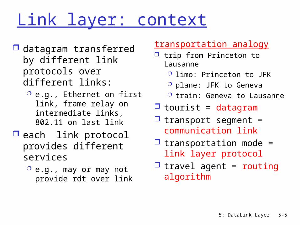
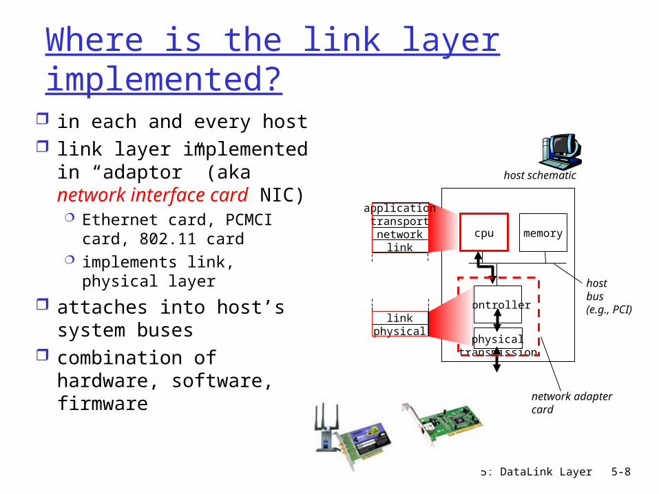
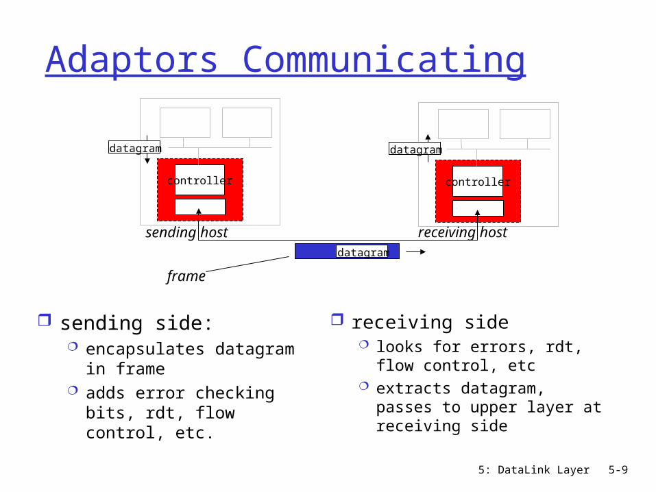
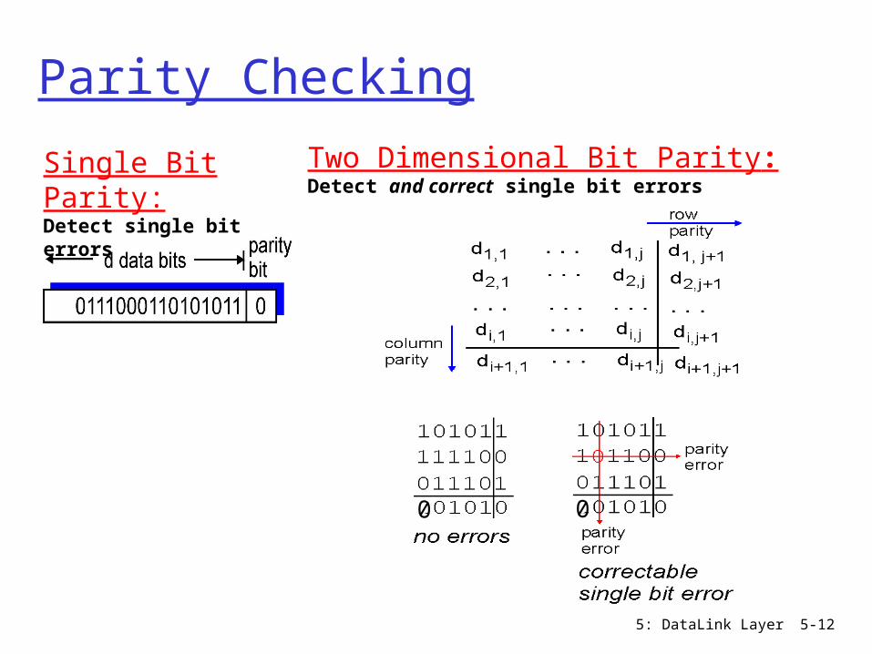
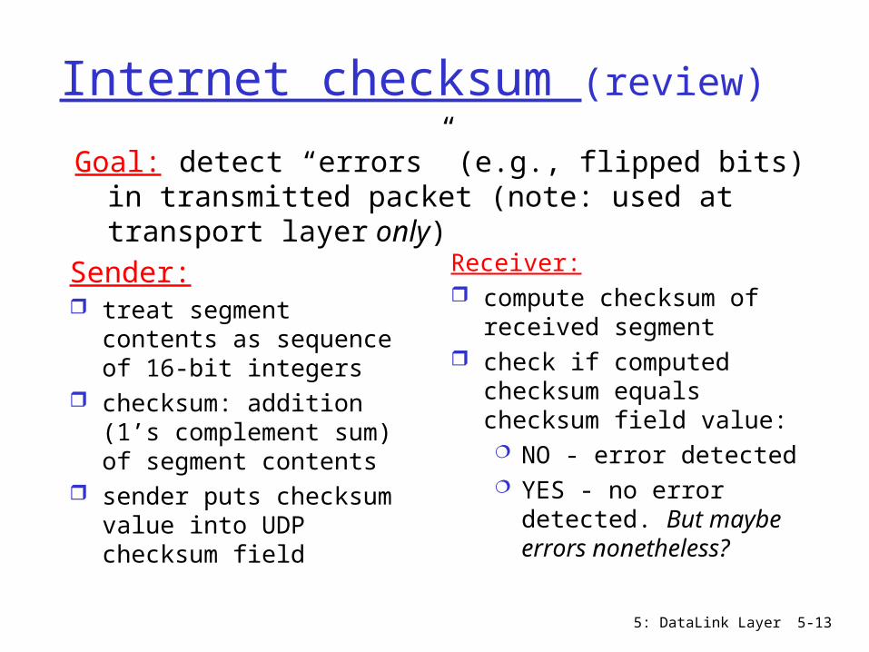
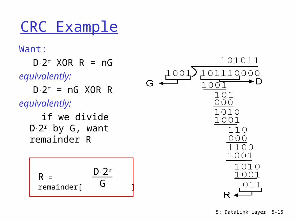
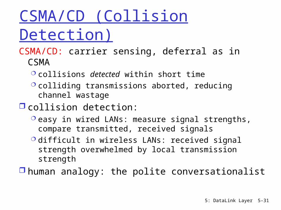
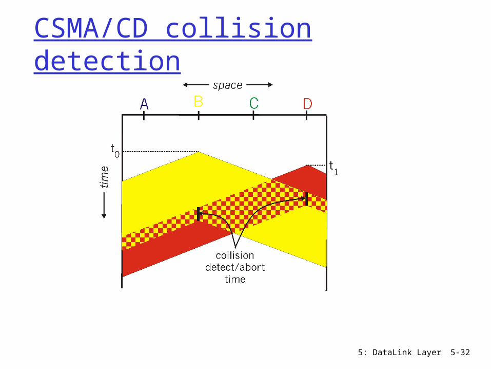
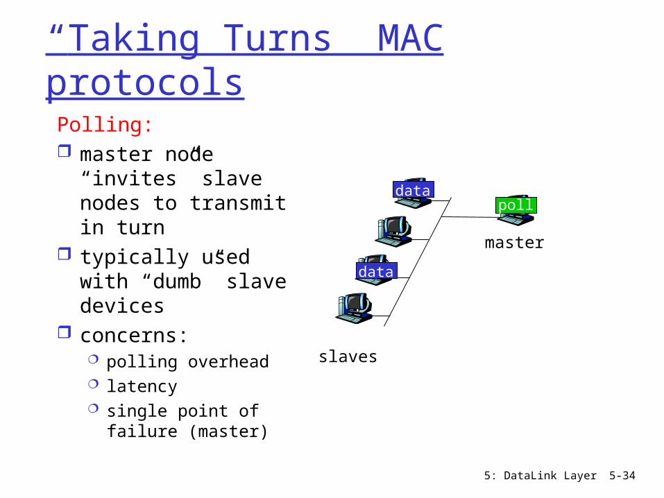
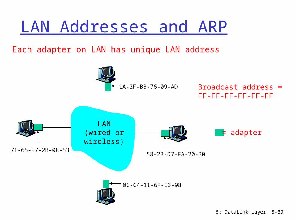
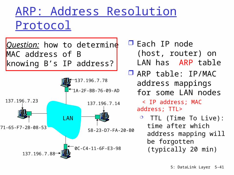
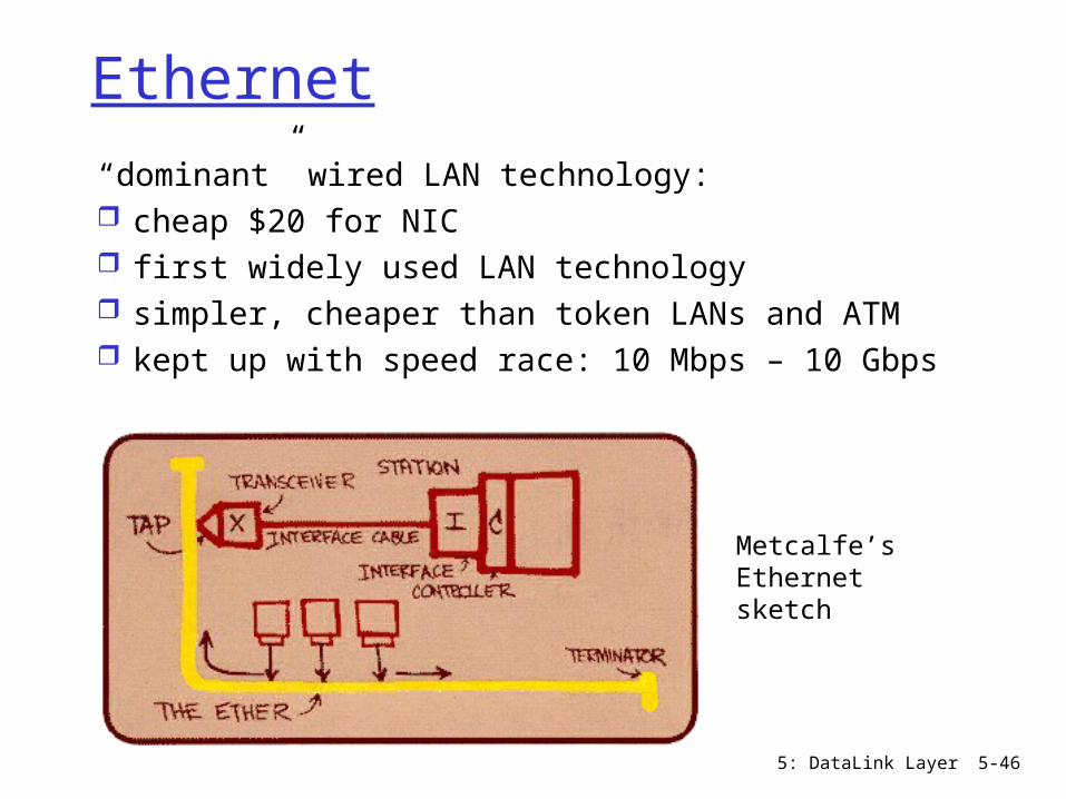
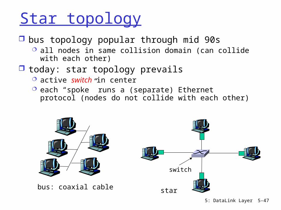
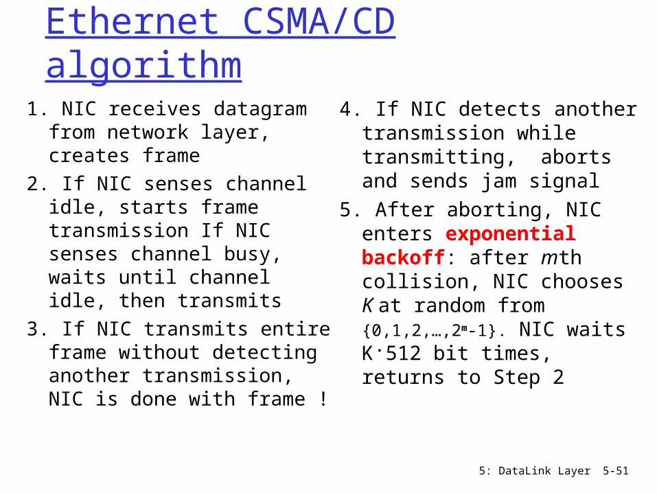
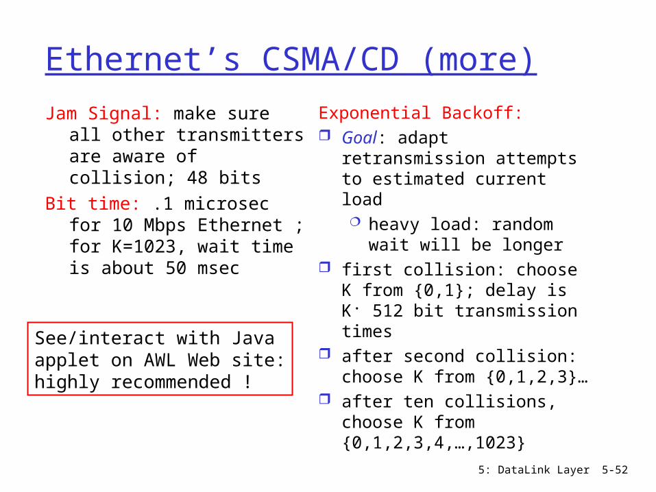
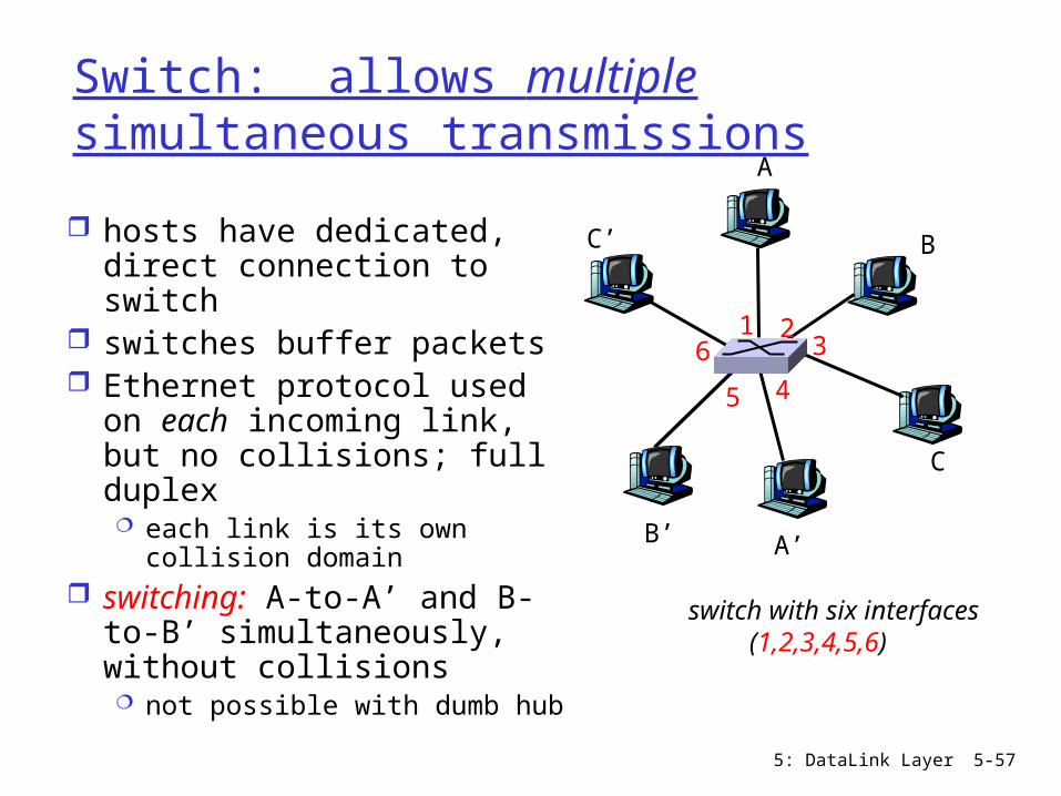
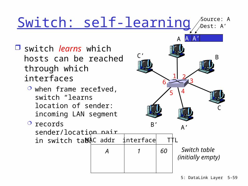
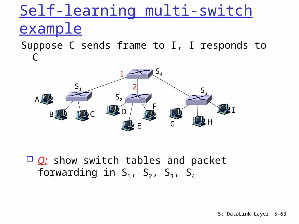
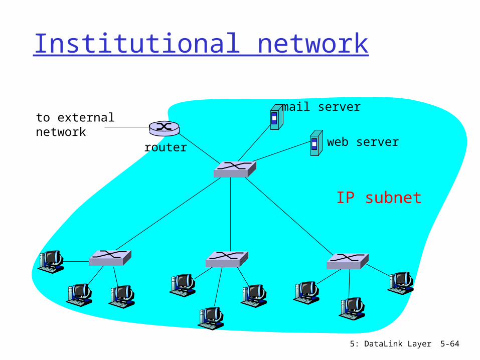
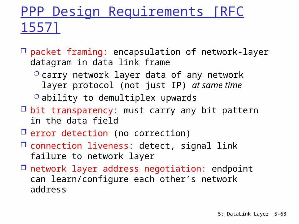
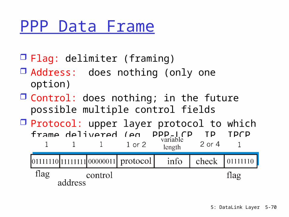
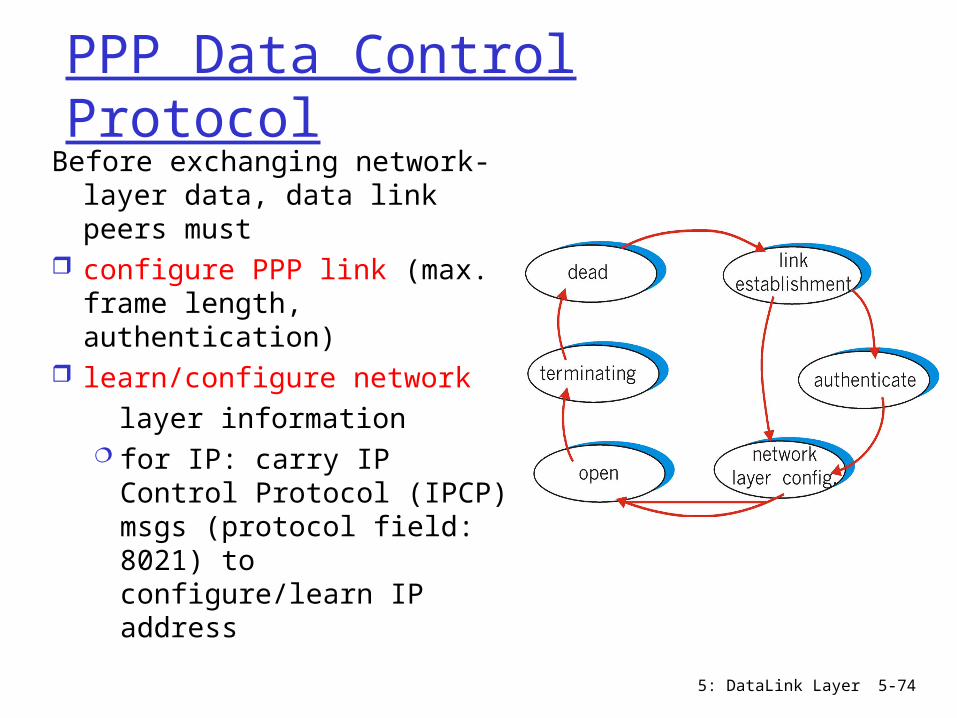