DANKO DEMO Q-0393 Specs-DWGS.pdf · DANKO DEMO Q-0393 11/14/13 Page 1 of ... This uniform method of...
42
DANKO DEMO Q-0393 11/14/13 Page 1 of 21 QUICK RESPONSE ATTACK UNIT NFPA 1906 COMPLIANCE The National Fire Protection Association “Standard for Wildland Fire Apparatus, 2012 Edition”, is hereby adopted and made a part of these specifications, the same as if it were written out in full detail, with the exception of the section dealing with "Equipment Recommended for Various Types of Apparatus". Bidders shall provide the equipment requested herein and the buyer shall supply the rest before the apparatus is put into service. NFPA STATEMENT OF EXCEPTIONS The proposed apparatus as described in this specification document does not meet the intent and applicable requirements based on the specified edition of NFPA in the following areas: The specified chassis does not meet the NFPA recommendation of section 14.1.3.4 which requires the seat belt webbing to be bright red or orange in color. This option is only available from the chassis manufacturer as a kit including a seat belt monitoring system and vehicle data recorder and was not requested/specified by the end user. The required “Equipment” as stated in the newest edition of NFPA 1906, section 5.7 shall be the responsibility of the purchaser unless otherwise specified in these specifications. VEHICLE STABILITY The apparatus shall comply with the vehicle stability requirements of the 2009 edition of NFPA 1901. The apparatus shall be considered substantially similar to a previously tested apparatus meeting the stability requirements based on section 4.13.1.1.2. TIRE PRESSURE INDICATING VALVE CAPS The apparatus shall be equipped with a visual indicator on each tire to warn the operator when tire pressure needs to be checked. APPARATUS BODY The apparatus body shall be designed to mount on a 60" cab to axle chassis. The body shall have overall dimensions of 96" wide x 120" long with a height of 60". The center cargo area shall be 52" wide, 43" high and extend the full length of the body. All body standard side compartments shall be 22" deep, with an approximate useable depth of 20".
Transcript of DANKO DEMO Q-0393 Specs-DWGS.pdf · DANKO DEMO Q-0393 11/14/13 Page 1 of ... This uniform method of...

DANKO DEMO Q-0393
11/14/13 Page 1 of 21
QUICK RESPONSE ATTACK UNIT
NFPA 1906 COMPLIANCE
The National Fire Protection Association “Standard for Wildland Fire Apparatus, 2012 Edition”, is hereby adopted and made a part of these specifications, the same as if it were written out in full detail, with the exception of the section dealing with "Equipment Recommended for Various Types of Apparatus". Bidders shall provide the equipment requested herein and the buyer shall supply the rest before the apparatus is put into service.
NFPA STATEMENT OF EXCEPTIONS
The proposed apparatus as described in this specification document does not meet the intent and applicable requirements based on the specified edition of NFPA in the following areas:
The specified chassis does not meet the NFPA recommendation of section 14.1.3.4 which requires the seat belt webbing to be bright red or orange in color. This option is only available from the chassis manufacturer as a kit including a seat belt monitoring system and vehicle data recorder and was not requested/specified by the end user.
The required “Equipment” as stated in the newest edition of NFPA 1906, section 5.7 shall be the responsibility of the purchaser unless otherwise specified in these specifications.
VEHICLE STABILITY
The apparatus shall comply with the vehicle stability requirements of the 2009 edition of NFPA 1901. The apparatus shall be considered substantially similar to a previously tested apparatus meeting the stability requirements based on section 4.13.1.1.2.
TIRE PRESSURE INDICATING VALVE CAPS
The apparatus shall be equipped with a visual indicator on each tire to warn the operator when tire pressure needs to be checked.
APPARATUS BODY
The apparatus body shall be designed to mount on a 60" cab to axle chassis. The body shall have overall dimensions of 96" wide x 120" long with a height of 60". The center cargo area shall be 52" wide, 43" high and extend the full length of the body. All body standard side compartments shall be 22" deep, with an approximate useable depth of 20".

DANKO DEMO Q-0393
11/14/13 Page 2 of 21
The body and compartments to be constructed entirely of fire apparatus quality aluminum sheets using the break-and-bend method of fabrication, then welded together. This uniform method of construction forms the aluminum into a strong, yet flexible structure. The complete body shall be of a modular design consisting of independent body modules and/or subassemblies and welded to an independent heavy duty support framework. The main body frame to consist of 6063-T52 extruded square tubing 2" x 2" x 1/4" wall, and extruded angle 2" x 2" x 1/4" thick. The cross members shall extend the full width of the body to support the compartments. There shall be a minimum of four (4) cross members spaced from front to rear. All body compartments and sides shall be fabricated with 3003-H14 smooth aluminum sheets. The compartments to have 3/16" smooth aluminum vertical sides, with double 90 degree bends on the outside to form a channel and a single bend on the inside back forming a 90 degree angle. Walkways, inside body floors, and a front gravel shield shall be 3003-H14 alloy 1/8" aluminum treadbrite. All body compartments shall be properly vented to relieve the pressure when opening and closing the compartment doors. The vents shall be mounted in a manner that will reduce the amount of dirt and water that may enter the compartment. The center cargo area floor shall be constructed with a combination of aluminum treadbrite and embossed aluminum treadbrite. The side compartments shall have smooth aluminum sweep-out type floors. The compartments shall be made to the largest practical dimensions to provide maximum storage capacity. All seams shall be sealed using a permanent pliable caulking. Polished aluminum rub rails 1-1/2" wide x 3/8" thick, to be furnished below the front and rear compartment doors on both sides of the apparatus body. The rub rails to be spaced 3/4" from the body enabling shock absorbency and cleaning ease. Spacers shall be nylon, with counter sunk stainless steel bolt fasteners for easy replacement. The rear fender wells shall be constructed of aluminum treadbrite, with a heavy-duty, polished extruded aluminum fenderette. A circular smooth aluminum inner wheel liner shall be furnished for each fender providing an easy to clean area. Sufficient clearance shall be provided to allow for the use of tire chains when the apparatus is fully loaded. The body shall be fastened to the chassis frame in six locations. There shall be two (2) spring loaded u-bolts at the front to allow flexing, two (2) rigid u-bolts near the center, and two bolts or tow eyes through the rear frame flange plate. A fuel fill pocket flange shall be supplied and mounted at the rear of the body. Two (2), mud flaps shall be supplied and mounted one on each side behind the rear wheels. The body shall carry a (7) seven-year structural warranty.

DANKO DEMO Q-0393
11/14/13 Page 3 of 21
REAR TAILBOARD
The rear tailboard framework shall be constructed, with 1-1/2" tubular steel and welded to the frame rails at the rear of the chassis. The tailboard shall be 8" in depth and the full width of the body, with a 1" space between the body and the tailboard. The framework to be covered with .125" aluminum NFPA approved embossed treadbrite to provide a slip resistant surface.
TOW EYES
Two (2), heavy duty chrome tow eyes, shall be installed at the rear of the body above the rear step. The tow eyes shall have a 2-3/16" inside diameter eye with a 1-1/4" threaded shaft and nut. The tow eyes will be fastened directly to each rear chassis frame rail.
COMPARTMENT DOORS
The door(s) to be lap type, with double panel construction. The outside door panel to be .190" 3003-H14 smooth alloy aluminum sheeting and the inner stiffener panel to be .125", 3003-H14 smooth alloy aluminum sheeting and hand swirled. There shall be a heavy-duty, automotive type, extruded rubber molding installed around the doors to insure a weatherproof seal. Compartment doors shall have polished stainless steel continuous hinge with a minimum of 1/4" diameter stainless steel pin and shall be fastened to the body with 1024 stainless steel bolts in such as manner so that the bolts will not be visible on the outside of the door. Door handles shall be 6-1/8" diameter stainless steel recessed type, with nondirectional bent "D" ring type handles. There shall be a polymer film placed between the handle and door to insulate dissimilar metals. An adjustable rotary D compartment latch with a center single point striker pin and double catch shall be furnished on all compartment doors to keep a tight seal. All vertically hinged swing-out compartment door(s) shall open from the rear of the body and be spring loaded to hold the door in an open or closed position. The spring loaded door holder shall close the door automatically when the door is positioned over center. All horizontally hinged lift-up compartment door(s) shall be furnished with two (2), pressurized, gas filled pneumatic cylinders. There shall be one cylinder on each side of the door to assist in raising and holding the door in the open position. The lift-up door(s) shall swing-up 30-degrees past horizontal position to allow for head clearance.

DANKO DEMO Q-0393
11/14/13 Page 4 of 21
LEFT SIDE COMPARTMENTS
There shall be a compartment located ahead of the rear wheels with an approximate door opening of 29-1/2" wide x 49" high and a single, vertically hinged swing-out door. There shall be a compartment located above the rear chassis wheels with an approximate door opening of 48" wide x 28" high and a single, horizontally hinged lift-up door. There shall be a compartment located behind the rear chassis wheels with an approximate door opening of 29-1/2" wide x 49" high and a single, vertically hinged swing-out door.
PRECONNECT HOSEBED
There shall be a preconnect hosebed built integral above the the left side compartments running the full length of the body. The hosebed shall be approximately 8" in height with approximately 8 cu. ft of storage space. This area shall be equipped with drain holes to allow standing water to exit. A hinged aluminum embossed treadbrite cover shall be supplied on the preconnect hosebed. The cover shall be fastened with stainless steel hinges to the outer-side of the body and equipped with a pressurized gas filled pneumatic cylinder to assist in raising and holding the cover in the open position. A chrome grab handle shall be mounted on the cover to aid in opening and closing the cover. A webbing restraint shall be located on the end of the hosebed to prevent unintentional deployment of hose. The webbing shall be opened and closed using lift-a-dot style fasteners which will also aid in preventing the cover from accidentally opening in route to the scene.
RIGHT SIDE COMPARTMENTS
There shall be a compartment located ahead of the rear chassis wheels with an approximate door opening of 29-1/2" wide x 49" high and a single, vertically hinged swing-out door. There shall be a compartment located above the rear chassis wheels with an approximate door opening of 48" wide x 28" high and a single, horizontally hinged lift-up door. There shall be a compartment located behind the rear chassis wheels with an approximate door opening of 29-1/2" wide x 49" high and a single, vertically hinged swing-out door.

DANKO DEMO Q-0393
11/14/13 Page 5 of 21
DUNNAGE STORAGE
There shall be a dunnage storage area built integral above the the right side compartments running the full length of the body. The dunnage area shall be approximately 8" in height and accessible from the top. This area shall be equipped with drain holes to allow standing water to exit. A hinged aluminum embossed treadbrite cover shall be supplied to enclose the dunnage storage area. The cover shall be fastened with stainless steel hinges to the outer-side of the body and equipped with a pressurized gas filled pneumatic cylinder to assist in raising and holding the cover in the open position. A chrome grab handle shall be mounted on the cover to aid in opening and closing the cover and an exterior hold-down latch will be provided to prevent the cover from accidentally opening in route to the scene.
HANDRAILS
Handrails to be round extruded aluminum with slip resistant rubber inserts. The handrail brackets to be brass, chrome plated and fastened to the body with stainless steel bolts. The hand rails shall be located in the following area(s): Two (2), vertical handrails shall be mounted one on each side at the rear of the body.
FOLDING STEPS
Steps to be 8" Die Cast Zinc/Aluminum Alloy folding type and to be mounted with stainless steel bolts. The surface area to be at least 35 square inches and withstand a load of at least 500 pounds. Each folding step shall be provided with an upper and lower LED light to illuminate the stepping areas as required by NFPA. The integral step lighting shall be activated when the emergency or park brake is set. The steps shall be located in the follows areas:
Six (6), folding steps shall be mounted at the rear of the body, three on each side.

DANKO DEMO Q-0393
11/14/13 Page 6 of 21
VERTICAL STRUT CHANNELS
The following compartments shall be equipped with vertical strut channels for the future installation of shelves: Left Front Side Compartment Left Rear Side Compartment Right Front Side Compartment Right Rear Side Compartment
ADJUSTABLE SHELVING
There shall be adjustable shelving constructed of 1/8" aluminum treadbrite, with a 2” lip bent up around the perimeter of the shelf. The shelves shall be located in the following compartment(s): One (1), left rear side compartment. One (1), right front side compartment.
ROLL-OUT EQUIPMENT TRAY
All selected roll-out equipment tray(s) to be constructed of 3/16" smooth aluminum with a 3" lip bent up around the perimeter of the tray, using the break and bend method. The tray shall be attached to a heavy-duty lock-in/lock-out slide with a front trigger release. The tray shall have a maximum capacity of 300 lbs. unless otherwise noted. The roll-out equipment tray(s) shall be located in the following compartments and permanently mounted to the floor: One (1), right rear side compartment.

DANKO DEMO Q-0393
11/14/13 Page 7 of 21
TURTLE TILE MATTING
Turtle Tile matting shall be provided with the completed apparatus. This style of matting is composed of ¾” recycled PVC with a grid style surface providing maximum drainage and traction. The matting shall be black in color with yellow edging when applicable. Matting shall be installed in the following areas of the apparatus: All body compartment floor(s) One (1), Preconnect Hosebed(s) One (1), Dunnage Storage Compartment(s) Two (2), Adjustable Shelve(s) One (1), Frame Depth Roll-Out Equipment Tray(s) NOTE: Matting shall be excluded in compartments utilizing a pump, booster reel and/or rollout frame.
CUSTOM CAB CONSOLE w/SWITCH PANEL
There shall be a custom console installed in the chassis cab between the front bucket seats. The console shall be used for mounting of siren controls and other instruments. The console shall be finished with a durable textured coating. An InPOWER switch module system shall be provided and mounted in the chassis cab. The switch module shall contain an adequate number of push button switches to be used for controlling the vehicle 12-volt auxiliary devices. All push buttons shall utilize a tactile switch design that ensures a positive operation. Each switch position contains a back lighted push button for night viewing, and a status LED indicator.
The switch module shall be connected to one or more power modules via a logic cable to provide power outputs and digital input system control. The power modules contain six 12-volt DC power outputs rated at 15 amps each, and include over current and short circuit automatic fault shutdown protection. Four digital inputs are provided from monitoring external conditions such as ignition switch on, transmission in Park, etc. and can be individually programmed.
DANKO DEMO Q-0393
11/14/13 Page 8 of 21
APPARATUS BODY 12-VOLT DISCONNECT
One (1), disconnect solenoid with a sufficient amp rating shall be wired from the battery and activated by the chassis ignition to disconnect all electrical accessories added by the body manufacturer. Items such as auxiliary engine starter, winch, booster reel(s), or high amp load items shall be excluded from the disconnect solenoid. One (1), reset breaker shall be installed between the solenoid output and any electrical load. One (1), indicator light shall be provided to indicate the apparatus 12-volt system is on. The light shall be located in the chassis cab and be visible from the driver’s positions. The light shall be green in color and labeled "BATTERY ON".
12-VOLT ELECTRICAL
All electrical equipment to be installed with high temperature, copper, multi-strand, crosslink-coated wire. Wiring to be colored coded and function labeled every 3” end to end. All wiring shall be enclosed in a protective loom throughout the system, with rubber grommets where the wiring passes through module walls. All exposed wire connections located under the body shall be sprayed with a clear flexible protective coating to block out moisture. The rear combination brake, turn, and stop tail lights to be LED 4" round with red lens. The rear back-up lights to be LED 4" round with clear lens. The lights to be connected to the transmission reverse switch. LED clearance lights shall be provided to comply with ICC regulations. The clearance lights shall be located one on each rear corner of the apparatus body and a triple red light cluster recessed at the rear center of the body for a total of five clearance lights. Reflectors shall be supplied on the perimeter of the apparatus as specified by ICC regulations. A lighted license plate bracket shall be mounted at the rear of the apparatus.

DANKO DEMO Q-0393
11/14/13 Page 9 of 21
COMPARTMENT LIGHTING
All compartments of the apparatus shall be equipped with Versa-Bryte LED style strip lighting. The lighting strips shall be sealed in a flexible water resistant plastic body with (9) LED’s every three inches and rated 50,000 hours with an output of 33.8 lumens for every 6”. This style of lighting will provide uniform and consistent illumination throughout the compartment and has a 3-year warranty. Each compartment door opening shall be supplied with one (1) lighting strip mounted vertically on the inside of the door opening and activated by an automatic switch located at each door.
HAZARD WARNING LIGHT
A red flashing LED hazardous warning light shall be mounted in the chassis cab. This light shall warn the operator of any open compartment doors, and/or other items permanently attached to the apparatus that may cause damage should the apparatus be moved. The warning light shall be marked with a sign that reads 'DO NOT MOVE APPARATUS WHEN LIGHT IS ON'. NOTE: This hazard light does not apply to manually raised pole lights with an extension of less than 5ft.
BACK-UP ALARM
The backup alarm shall be an electronic 97-decibel rated alarm installed at the rear of the vehicle. This alarm shall alert personnel any time the transmission is shifted into reverse.
SIREN
One (1), Whelen model 295HFS2 100/200 watt selectable output electronic siren with a flush mount controlhead shall be supplied and installed in the cab. This siren is a full function system including radio repeat, public address, SI-Test, 17 scan-lock selectable siren tones and a unidirectional pre-wired microphone. This siren has a five (5) year HDP®, heavy duty professional, warranty.
SPEAKER
One (1), 100-Watt speaker shall be mounted at the front of the apparatus.

DANKO DEMO Q-0393
11/14/13 Page 10 of 21
LIGHTING PACKAGE
All warning and signal light switches shall be provided with an indicator light and located inside the chassis cab. UPPER ZONE A (Front) One (1), Whelen Justice JE2NFPA 56" LED light bar shall be supplied and installed on the chassis roof. The lightbar shall have four corner red Linear-LEDs and six front CON3 LEDs (4-Red/2-White). All white forward facing emergency lights in the light bar shall be deactivated when the parking brake is engaged in the Blocking Right of Way mode as required by NFPA. LOWER ZONE A (Front) Two (2), Whelen LINZ6R series, Super-LED lights shall be installed at the front of the apparatus, one on each side with a chrome flange. The lighthead shall have red LEDs and a clear lens cover. ZONE B (Right Side) One (1), Whelen LINZ6R series, Super-LED lights shall be installed on the right side of the apparatus towards the front with a chrome flange. The lighthead shall have red LEDs and a clear lens cover. One (1), Whelen LINZ6R series, Super-LED light shall be installed on the right side of the apparatus towards the rear with a chrome flange. The lighthead shall have red LEDs and a clear lens cover. UPPER ZONE C (Rear) Two (2), Whelen LINZ6R series, Super-LED lights shall be installed on the rear upper section of the apparatus, one on each side with a chrome flange. The lighthead shall have red LEDs and a clear lens cover. LOWER ZONE C (Rear) Two (2), Whelen LINZ6R series, Super-LED lights shall be installed at the rear lower section of the apparatus, one on each side with a chrome flange. The lighthead shall have red LEDs and a clear lens cover. ZONE D (Left Side) One (1), Whelen LINZ6R series, Super-LED lights shall be installed on the left side of the apparatus towards the front with a chrome flange. The lighthead shall have red LEDs and a clear lens cover. One (1), Whelen LINZ6R series, Super-LED light shall be installed on the left side of the apparatus towards the rear with a chrome flange. The lighthead shall have red LEDs and a clear lens cover.

DANKO DEMO Q-0393
11/14/13 Page 11 of 21
SCENE LIGHTS
Whelen M6ZC series Linear-LED scene lights featuring inner optics to direct the light downward shall be provided with the completed apparatus and mounted in the following areas:
Two (2), Whelen M6ZC LED scene lights shall be mounted on the left upper side of the apparatus body.
Two (2), Whelen M6ZC LED scene lights shall be mounted on the right upper side of the
apparatus body. A Whelen M6FC chrome flange shall be provided.
Two (2), Whelen M6ZC LED scene lights shall be mounted at the rear of the apparatus body. A Whelen M6FC chrome flange shall be provided.
The left side scene lights shall be activated by a lighted rocker switch located in the chassis cab. The switch shall be labeled "LEFT SCENE.” The right side scene lights shall be activated by a lighted rocker switch located in the chassis cab. The switch shall be labeled "RIGHT SCENE.” The rear scene lights shall be activated by a lighted rocker switch located in the chassis cab. The switch shall be labeled "REAR SCENE.”
GROUND LIGHTING
Lights shall be installed beneath the apparatus in areas where personnel may be expected to climb on and off of the apparatus. The lights shall illuminate the ground within 30" of the apparatus to provide visibility of any obstructions or hazards. These areas shall include, but not be limited to the cab doors, running boards, and the rear step area. The ground lighting shall be activated when the emergency or park brake is set.
SURFACE LIGHTING
The completed apparatus shall have sufficient lighting provided on the apparatus as per NFPA requirements to illuminate the following surfaces: Rear Backup Lights will be Illuminated to Light the Rear Step Surface The surface lighting shall be activated when the emergency or park brake is set.

DANKO DEMO Q-0393
11/14/13 Page 12 of 21
PAINTING
After the apparatus body and components have been fabricated and assembled, the apparatus body shall be completely sanded and deburred for removal of sharp edges. The apparatus and components shall be metal prepped to provide a superior substrate for painting. The apparatus body and components shall undergo a degreasing/cleaning process, starting with a clear, acidic liquid, designed to remove surface soils and oxidation. This process develops a light phosphate coating, which gives aluminum a superior base for good paint adhesion. The apparatus body shall be painted to match the color of the chassis as received from the chassis manufacturer as follows:
BODY PAINT COLOR: REDPAINT BRAND: PPG
PAINT NUMBER: ***** After the cleaning process, a fast build epoxy primer shall be applied and sanded prior to the top finish coatings. The finish painting process shall consist of applying two (2), coats of high quality, 3.5 VOC polyurethane paint to maintain proper film thickness. The completed apparatus shall be free of blistering, peeling and any other adhesion defect caused by defective manufacturing methods or paint material selection for metal exterior surfaces for a period of five (5) years.
OEM PAINTED CHASSIS CAB
The chassis cab shall be as painted from the chassis manufacturer.
OEM ALUMINUM CHASSIS RIMS
The chassis rims shall be ordered as aluminum from the chassis manufacturer.
BODY UNDERCOATING
The entire underside of the body shall be coated with a tough, pliable, rubberized coating for protection against abrasion and corrosion. This hybrid undercoating features a water based formula with quick dry capability to achieve early water and weather resistance. The undercoating shall be applied prior to installation of the body onto the chassis to avoid spraying the product on air lines, cables, or other items that would cause normal maintenance to be hindered.

DANKO DEMO Q-0393
11/14/13 Page 13 of 21
COMPARTMENT INTERIOR
The interior compartments shall be painted using a white finish with a black and job color splatter. This coating system provides a durable finish with easy maintenance.
SPECIAL LABELS
All labeling shall meet the 2012 edition of NFPA 1906. A permanent plate shall be affixed to the completed vehicle specifying the quantity and type of the following fluids that may be used in the apparatus for normal maintenance. Where a fluid is not applicable to the unit, the plate shall be marked N/A to inform the service technician who may not be familiar with the apparatus.
APPARATUS FLUIDSEngine Oil Pump Transmission Lubrication Fluid Engine Coolant Pump Primer FluidTransmission Fluid Air Compressor System LubricantDrive Axle Lubrication Fluid Generator System LubricantTransfer Case Fluid Equipment Rack FluidPower Steering Fluid Front Tire Cold PressureAir Conditioning Refrigerant Rear Tire Cold Pressure Air Conditioning Lubrication Oil Other:: Cab Tilt Mechanism Fluid Misc: ** Sample Label for Reference Only.
A permanent label shall be affixed in the driver's area that states the maximum number of personnel allowed to ride on the apparatus at any time. A sign shall be affixed in the chassis cab, in plain sight of the driver, that states the overall travel height of the apparatus. A sign shall be affixed in the chassis cab, in plain sight of the driver, that states the overall travel length of the apparatus. A sign that reads “OCCUPANTS MUST BE SEATED AND SEAT BELTS MUST BE FASTENED WHEN APPARATUS IS IN MOTION” shall be visible from each seated position. A sign that reads “DO NOT WEAR HELMET WHILE SEATED” shall be visible from each seated position. Any other appropriate label(s) shall be affixed in noticeable locations to ensure the safe operation of the apparatus.

DANKO DEMO Q-0393
11/14/13 Page 14 of 21
NFPA COMPLIANT REFLECTIVE STRIPING
Reflective striping shall be applied to the exterior of the apparatus in a manner consistent with the National Fire Protection Association Pamphlet 1901, latest edition. It shall consist of a White Scotchlite 4" reflective stripe, affixed to the exterior perimeter of the apparatus body and chassis cab. A white reflective stripe shall also be applied to the interior of each chassis cab door and/or any equipment such as roll-out trays or frames that protrude beyond the body of the apparatus to indicate a hazard or obstruction. An additional reflective stripe shall be mounted on the body rubrails. The color of the stripe shall be white unless otherwise specified.
CHASSIS MODIFICATIONS
The chassis SEIC (Stationary Engine Idle control) system shall be wired to engage automatic high idle when the emergency brake is applied. A UREA tank fill flange shall be supplied and mounted on the left side of the apparatus.
REAR RECEIVER TUBE
A Class III 2" receiver tube shall be installed at the rear of the apparatus with two safety chain attachment points. The receiver tube shall be rated up to 5,000 lbs maximum trailer weight and 500 lbs maximum tongue weight. A label shall be placed near the receiver stating the maximum trailer weight, tongue weight and straight line pull rating. One (1), 7-prong connector with a weatherproof cover shall be supplied and mounted near the rear receiver tube.
MANUALS
Two (2), set(s) of manufacturer operation and maintenance manuals covering the completed apparatus as delivered, including but not limited to the chassis, wiring diagrams, or any other documents or technical data referencing the apparatus. Also included shall be any manufacturers warranties and/or guarantees.
DANKO DEMO Q-0393
11/14/13 Page 15 of 21
DANKO BRUSHWACKER SKID UNIT 300 Gallon Polypropylene Defender 2C Skid Unit
The skid unit shall be mounted on the above specified fire apparatus and connected to the 12-volt electrical system. The unit shall be built according to the following specifications:
ALUMINUM FRAME
A heavy duty aluminum frame shall be constructed with a combination of 2" x 2" x 1/8" square aluminum tubing and 1-1/2" x 1-1/2" x 1/4" aluminum angle supports. The frame will provide a secure means of attaching the fire pump and water tank together as one unit to be mounted onto a truck or flatbed.
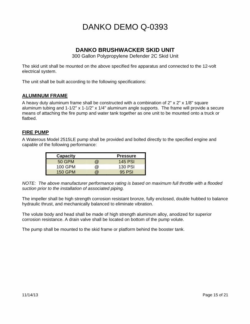
FIRE PUMP
A Waterous Model 2515LE pump shall be provided and bolted directly to the specified engine and capable of the following performance:
Capacity Pressure50 GPM @ 145 PSI
100 GPM @ 130 PSI 150 GPM @ 95 PSI
NOTE: The above manufacturer performance rating is based on maximum full throttle with a flooded suction prior to the installation of associated piping. The impeller shall be high strength corrosion resistant bronze, fully enclosed, double hubbed to balance hydraulic thrust, and mechanically balanced to eliminate vibration. The volute body and head shall be made of high strength aluminum alloy, anodized for superior corrosion resistance. A drain valve shall be located on bottom of the pump volute. The pump shall be mounted to the skid frame or platform behind the booster tank.

DANKO DEMO Q-0393
11/14/13 Page 16 of 21
PUMP ENGINE
A Kubota D902-EB vertical 4-cycle liquid cooled 23 HP diesel engine shall be supplied and mounted to the pump. This engine shall be constructed of Dura-Bore cast iron cylinder sleeves, and also feature easy one-sided maintenance, a full pressure lubrication system with an automotive style oil filter and oil fill tube with dipstick. The electric starter on pump engine shall be connected to the 12-volt electrical system. The engine shall have a two-year (2,000 hr) warranty.
PUMP ENGINE START CONTROL MODULE
A Deep Sea DSE3110 manual and auto start control module shall be provided and mounted near the pump engine. The control module shall feature a back-lit LCD display, start input, and full engine monitoring and protection.
PUMP ENGINE THROTTLE
The pump engine shall be supplied with a vernier style throttle mounted near the pump operators position. The operation of the remote throttle shall consist of seven full turns from idle to wide open engine speed. The throttle shall have a red center button to quickly return the engine to idle when depressed.
PUMP PANEL LIGHT
The pump operator's control panel shall be illuminated with a shield installed over the light to protect it from the elements. A properly labeled on/off switch shall be supplied and mounted on the operators panel.
PUMP ENGINE OIL DRAIN
The pump engine oil drain shall be piped away from the engine below the apparatus with a drain plug.
PUMP ENGINE FUEL SYSTEM
The pump engine shall be connected directly to the chassis fuel tank if a common fuel is used. The fuel line shall be connected from the pump engine to an electric fuel pump with a separate siphon tube. (NO EXCEPTIONS)

DANKO DEMO Q-0393
11/14/13 Page 17 of 21
GUZZLER PRIMER
Priming shall be accomplished with a Guzzler Model 400H 3/4" hand pump primer with double sided diaphragm.
DISCHARGE PRESSURE GAUGE
There shall be one (1), discharge pressure gauge installed in the pressure side of the plumbing. The gauge shall be a minimum of 2-1/2" in diameter.
PLUMBING
Plumbing shall be a combination of 300 PSI hose and heavy duty stainless steel pipe and fittings. All discharges and intake adapters to be brass chrome plated. The stainless steel plumbing shall not be painted. All valves shall be brass Watts full flow quarter-turn valves. A stainless steel welded pipe manifold shall be attached to the pump discharge with four (4) ¼” bolts to facilitate all outlets and reduce friction loss. The manifold assembly shall be constructed of 2” round tubing and capable of accommodating up to two (2) 1” discharges and three (3) 1-1/2” discharge outlets. A stainless steel welded pipe manifold shall be attached to the suction side of the pump with a Victaulic clamp for easy removal for service and maintenance. The manifold shall have a tee to facilitate a 2” tank to pump and 2-1/2” intake.
TANK TO PUMP
One (1), tank to pump valve shall be a 2" Watts full flow quarter turn ball valve with a flexible hose to reduce vibration of the pump engine.
PUMP TO TANK/RECIRCULATE VALVE
One (1), 1" tank fill or recirculate line with a quarter-turn ball valve plumbed directly from the pump discharge to the tank with a flexible hose to reduce vibration of the pump engine.

DANKO DEMO Q-0393
11/14/13 Page 18 of 21
INTAKE
One (1), 2-1/2" male intake shall be mounted to the pump inlet. The intake shall terminate with a chrome 2-1/2" NPT female x 2-1/2" NH male fitting with a screen to prevent foreign objects from entering the pump. One (1), 2-1/2” NH chrome cap with chain shall be supplied for the intake.
PRECONNECT DISCHARGE
One (1), 1-1/2" NH gated discharge preconnect with 1-1/2" quarter-turn ball valve(s), to be located at the left side preconnect hosebed.
1” DISCHARGE
One (1), 1" NH discharge shall be provided with a 1” Watts full flow quarter-turn valve. The discharge shall terminate with a chrome 1” NPT male x 1” NH male fitting and be directed to the rear of the skid. One (1), 1" NH chrome cap with chain shall be supplied for the discharge.
1-1/2” DISCHARGE
One (1), 1-1/2" NH discharge shall be provided with a 1-1/2” Watts full flow quarter-turn valve. The discharge shall terminate with a chrome 1-1/2” NPT male x 1-1/2” NH male fitting and be directed to the rear. One (1), 1-1/2" NH chrome cap with chain shall be supplied for the discharge.
REEL AND BOOSTER HOSE
One (1), Hannay model EF4040-17-18RT steel electric booster reel, with a capacity of 150' of 1"booster hose shall be supplied. The reel shall be painted graphite in color. A 1" quarter turn ball valve shall be piped from the pump discharge and connected to the booster reel with a flexible hose to reduce vibration from the pump engine. One (1), set of chrome guide rollers shall be mounted high on the left side of the hose reel. The rollers shall provide assistance in pulling the hose off from the reel and guiding it on after use. One (1), booster reel rewind switch shall be located on the left side of the skid unit. One (1), 1" x 150' section of 300 lb. working pressure rubber booster hose coupled with 1" NH couplings shall be supplied for the booster reel(s). The booster reel shall be mounted crosswise above the booster tank and deploy to the rear of the apparatus.

DANKO DEMO Q-0393
11/14/13 Page 19 of 21
SCOTTY THROUGH THE PUMP FOAM EDUCTOR/MIXER
The Scotty "Through the Pump" foam system model 4171-NH shall be supplied and mounted to the fire unit. The Scotty system is a low-energy system as it introduces ambient air in the foam solution through the discharge. This system is calibrated to educt foam concentrate at a variable percentage into flows from 15 up to 100 gpm at 100 psi. NOTE: When the through the pump foam system is in operation you cannot recirculate the water flow.
FOAM CELL
One (1), twelve (12) gallon foam cell shall be constructed by UPF as an integral part of the polypropylene water tank. The foam cell can be used for either Class A or AFFF (class B) foam and be completely resistant to any reaction caused by the foam or any additives that may be used under normal circumstances. The seams shall be nitrogen welded and spark tested for maximum strength. The foam cell shall have a cover attached with mechanical fasteners to allow access for inspection/cleaning. The foam tank shall have a manual fill tower with lid. The fill tower shall be constructed of 1/2" PT3™ polypropylene and shall be a minimum dimension of 8" x 8" outer perimeter with a molded cover. The molded cover shall be fastened to the tower with a tether to prevent loss. The top of the foam fill tower shall be constructed of a GREEN material indicating Class A, or Yellow material indicating Class B for each type of foam to be utilized. The capacity of the tank shall be engraved on the top of the fill tower lid. The tower shall be located as indicated by the apparatus manufacturer. The tower shall have a 1/4" thick removable polypropylene screen. Inside the fill tower, approximately 1.5” down from the top, there shall be an anti-foam fill tube that extends down to the bottom of the tank. A pressure vacuum vent shall be provided in the lid of the fill tower. There shall be two (2) standard connections located on the same plain of the foam cell wall. The two (2) connections shall be 1/2" FNPT suction connections. A 1/2" shut-off valve shall be installed between the foam cell and the foam system for ease of maintenance.

DANKO DEMO Q-0393
11/14/13 Page 20 of 21
BOOSTER TANK
The water tank shall be a UPF Defender 2C series tank with a capacity of 300 US gallons. (Approximate tank dimensions: 60L x 46W x 31H) The tank shall have a LIFETIME WARRANTY as supplied by the tank manufacturer. The tank shall be constructed of black 1/2" thick UPF PT-2E textured polypropylene sheet stock with AccTuff resin. The material shall be of a certified, virgin, high quality, noncorrosive, stress relieved thermo plastic. The tank shall be designed to have complete modular drop-in capability. All joints and seams are to be fusion welded and electronically and hydrostatically tested for maximum strength. The unit shall incorporate transverse and longitudinal partitions manufactured of 3/8" UPF PT2E polypropylene (natural in color) which shall interlock. All swash partitions shall be so designed to allow for maximum water and air flow between compartments and are completely welded to each other as well as to the inside of the tank. The passenger side rear wall of the tank shall have an internal liquid sight gauge 4" in width, natural in color, and 80% transparent. The tank shall be equipped with a combination vent/overflow and manual fill tower. The fill tower shall be 8" round and 8" high with a round molded cover. The cover shall be fastened to the tower with a tether to prevent loss. The tower shall be located in the rear passenger's side corner. There shall be a vent/overflow installed inside the tower approximately 2" down from the top. This vent/overflow shall be schedule 40 polypropylene pipe and have an ID of 3". The vent/overflow shall be piped internally toward the passenger side and exit the tank through the sidewall. The overflow pipe shall be flush with the sidewall. There shall be one sump as standard per tank. The sump shall be recessed into the tank floor and be a minimum of 1/4" deep. There shall be two standard outlets located on the same vertical plane on the driver's side rear tank wall. One (1) 3" FNPT suction fitting and one (1) 1-1/2" FNPT tank fill with flow deflector. The cover shall incorporate two (2) mounting blocks that shall be slotted to accommodate two (2) each 3/8" - 16 threading sliding fasteners. These mounting blocks shall be welded to the covers running from the rear edge of the tank forward. The UPF Defender 2C shall have provisions on the tank for mounting both front and rear to secure the tank to the skid base. There shall be a 1" FNPT female tank drain located on the rear tank wall towards the passenger side with a 1" stainless steel plug.

DANKO DEMO Q-0393
11/14/13 Page 21 of 21
12-VOLT ELECTRICAL
All electrical components of the unit shall be wired to a terminal stud block with high temperature, copper, multi-strand, crosslink-coated wire enclosed in a protective loom.
PUMP WORK LIGHT
One (1), 12-Volt work light shall be mounted on the tank to light up the work area. An ON/OFF switch shall be provided and mounted near the operators position.
WATER LEVEL GAUGE
One (1), Innovative Controls Inc. electronic water level fluid meter with a sealed probe shall be mounted into the tank. The indicator panel shall feature high intensity LED's and display FULL, 3/4, 1/2, 1/4 and REFILL levels that are easily distinguished at a glance. Level Monitor accuracy is enhanced by an "anti-slosh" feature, which provides steady, accurate fluid level indication despite sloshing inside the tank due to vehicle motion. The water level gauge shall be located on the left side at the rear of the skid unit. There shall be one (1) Innovative Controls, miniature LED water display located inside the chassis cab in clear view of the driver and/or passenger.
WARRANTY
Danko Emergency Equipment Co shall warrant to each original purchaser that the Danko apparatus is free of defects in material and workmanship for a period of one (1) year after the date on which the unit is first accepted.
Prepared For: Prepared By:Danko Demo Q-0393Snyder, Nebraska David KnobbeDanko Emergency Equipment
302 East 4th StreetSnyder, Nebraska, 68664Phone: (402) 568-2200Fax: (402) 568-2278Email: [email protected]
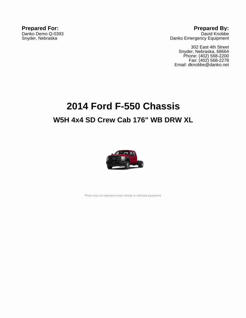
2014 Ford F-550 Chassis
Photo may not represent exact vehicle or selected equipment.
W5H 4x4 SD Crew Cab 176" WB DRW XL

2014 Ford F-550 Chassis
VEHICLE REPORT 2014 Ford F-550 Chassis W5H 4x4 SD Crew Cab 176" WB DRW XL
SELECTED MODEL
Code Description
W5H 2014 Ford F-550 Chassis 4x4 SD Crew Cab 176" WB DRW XL
SELECTED VEHICLE COLORSCode Description
- Interior: STEEL- Exterior 1: VERMILLION RED- Exterior 2: No color has been selected.
Code Description Class
SELECTED OPTIONS
660A OPTOrder Code 660A
99T OPTEngine: 6.7L 4V OHV Power Stroke Diesel V8 B20200 Amp Extra Heavy Duty Alternator; (X41) 4.10 Axle Ratio; Dual 78 AH Batteries.Includes clean idle decal and intelligent oil life minder.
44W OPTTransmission: TorqShift 6-Speed Auto w/ODIncludes SelectShift.
X8L OPTLimited Slip w/4.88 Axle Ratio68M OPTGVWR: 19,500 lb Payload Plus Upgrade Package
Includes upgraded frame, upgraded springs and low deflection/high capacity.Increases max RGAWR to 14, 706. NOTE: See Order Guide Supplemental Referencefor further details on GVWR.
TGB OPTTires: 225/70Rx19.5G BSW Max TractionIncludes 4 traction tires on the rear and 2 traction tires on the front. Not recommendedfor over the road applications; could incur irregular front tire wear and/or NVH.Optional spare is traction.
Page 2
Report content is based on current data version referenced. Any performance-related calculations are offered solely as guidelines. Actual unit performance will depend on your operatingconditions. PC Carbook®, Data Version: 30.0, Data updated 09/26/2013 07:54:42 PM ©Copyright 1986-2012 Chrome Data Solutions, LP. All rights reserved.November 14, 2013

2014 Ford F-550 Chassis
VEHICLE REPORT 2014 Ford F-550 Chassis W5H 4x4 SD Crew Cab 176" WB DRW XL
Code Description Class
SELECTED OPTIONS
64Z INCWheels: 19.5" Argent Painted Steel (6)
A INCHD Vinyl 40/20/40 Split Bench SeatIncludes driver side manual lumbar support, center armrest, cupholder and storage.
PAINT STDMonotone Paint Application176WB STD176" Wheelbase531 OPTTrailer-Tow Package
Trailer brake controller not included. Includes aftermarket trailer brake wiring kit.NOTE: Salesperson's Source Book or Ford RV Trailer-Towing Guide should beconsulted for specific trailer towing or camper limits and corresponding requiredequipment, axle ratios and model availability.
96P OPTXL Appearance Package(585) Radio: AM/FM Stereo/Single CD/MP3 : Includes digital clock, 4 speakers andauxiliary audio input jack.; Bright Chrome Grille Surround w/Black Insert; (17F) XLDecor Group; Cruise Control
17F INCXL Decor GroupChrome Front Bumper
90L OPTPower Equipment GroupAccessory Delay; Power Locks; Remote Keyless Entry; Perimeter Anti-Theft Alarm;Power Front & Rear Side Windows : Includes 1-touch up and down power driver andpassenger window.; MyKey : Includes owner controls feature.; Manual TelescopingTrailer-Tow Mirrors : Includes power heated glass, heated convex spotter mirror andintegrated clearance lights/turn signals.; SecuriLock Passive Anti-Theft System(PATS). Deletes passenger-side lock cylinder. Includes upgraded door-trim panel.
41H OPTEngine Block Heater62R OPTTransmission Power Take-Off Provision98R INCOperator Commanded Regeneration (OCR)67A INCDual Alternators (Total 357-Amps)
Page 3
Report content is based on current data version referenced. Any performance-related calculations are offered solely as guidelines. Actual unit performance will depend on your operatingconditions. PC Carbook®, Data Version: 30.0, Data updated 09/26/2013 07:54:42 PM ©Copyright 1986-2012 Chrome Data Solutions, LP. All rights reserved.November 14, 2013

2014 Ford F-550 Chassis
VEHICLE REPORT 2014 Ford F-550 Chassis W5H 4x4 SD Crew Cab 176" WB DRW XL
Code Description Class
SELECTED OPTIONS
585 INCRadio: AM/FM Stereo/Single CD/MP3Includes digital clock, 4 speakers and auxiliary audio input jack.
47J OPTFire/Rescue Prep Pkg w/EPA Special Emissions (LPO)(67A) Dual Alternators (Total 357-Amps); (98R) Operator Commanded Regeneration(OCR). Includes max front springs/GAWR rating for configuration selected. IncludesEPA Special Emergency Vehicle Emissions. Incomplete vehicle package - requiresfurther manufacture and certification by a final stage manufacturer. Ford urgesFire/Rescue Vehicle manufacturers to follow the recommendations of the FordIncomplete Vehicle Manual and the Ford Truck Body Builders Layout Book (andpertinent supplements). NOTE 1: Stationary Elevated Idle Control (SEIC) has beenintegrated into the engine control module. NOTE 2: Engine calibration significantlyreduces the possibility of depower mode when in stationary PTO operation. NOTE 3:Operator commanded regen down to 30% of DPF filter full, instead of 100%. NOTE 4:Must meet the definition of an Emergency Vehicle, an Ambulance or Fire Truck per 40CFR 86.1803.01 in the Federal Register. REQUIRES valid FIN code.
AS OPTSteel
F1 OPTVermillion Red
OPTIONS TOTAL
Page 4
Report content is based on current data version referenced. Any performance-related calculations are offered solely as guidelines. Actual unit performance will depend on your operatingconditions. PC Carbook®, Data Version: 30.0, Data updated 09/26/2013 07:54:42 PM ©Copyright 1986-2012 Chrome Data Solutions, LP. All rights reserved.November 14, 2013

2014 Ford F-550 Chassis
VEHICLE REPORT 2014 Ford F-550 Chassis W5H 4x4 SD Crew Cab 176" WB DRW XL
STANDARD EQUIPMENTPowertrain
Powerstroke 300hp 6.7L OHV 32 valve intercooled turbo V-8 engine with direct diesel injection
Recommended fuel : diesel
Engine block heater
Emissions Type: federal
6 speed automatic transmission with overdrive, SelectShift sequential sport shift, driver mode select
Part-time 4 wheel drive
Limited slip differential
Fuel Tank Capacity: 40.0gal.
Suspension/HandlingFront Mono-beam non-independent suspension with anti-roll bar, HD shocks
Rear rigid axle leaf suspension with anti-roll bar, HD shocks
Firm ride suspension
Hydraulic power-assist re-circulating ball steering
Front and rear 19.5" x 6" argent steel wheels
LT225/70SR19.5G BSW AT front and rear tires
Dual rear wheels
Body Exterior4 doors
Conventional left rear passenger door
Conventional right rear passenger door
Page 5
Report content is based on current data version referenced. Any performance-related calculations are offered solely as guidelines. Actual unit performance will depend on your operatingconditions. PC Carbook®, Data Version: 30.0, Data updated 09/26/2013 07:54:42 PM ©Copyright 1986-2012 Chrome Data Solutions, LP. All rights reserved.November 14, 2013

2014 Ford F-550 Chassis
VEHICLE REPORT 2014 Ford F-550 Chassis W5H 4x4 SD Crew Cab 176" WB DRW XL
STANDARD EQUIPMENTBody Exterior (Continued)
Driver and passenger power remote heated door mirrors
Turn signal indicator in mirrors
Black door mirrors
Chrome front bumper
Trailer harness
Clearcoat paint
ConvenienceManual air conditioning
Cruise control with steering wheel controls
Power windows
Driver and passenger 1-touch down
Driver and passenger 1-touch up
Remote power door locks with 2 stage unlock and illuminated entry
Manual tilt steering wheel
Manual telescopic steering wheel
Day-night rearview mirror
Front cupholders
Passenger visor vanity mirror
Full overhead console
Driver and passenger door bins
Page 6
Report content is based on current data version referenced. Any performance-related calculations are offered solely as guidelines. Actual unit performance will depend on your operatingconditions. PC Carbook®, Data Version: 30.0, Data updated 09/26/2013 07:54:42 PM ©Copyright 1986-2012 Chrome Data Solutions, LP. All rights reserved.November 14, 2013

2014 Ford F-550 Chassis
VEHICLE REPORT 2014 Ford F-550 Chassis W5H 4x4 SD Crew Cab 176" WB DRW XL
STANDARD EQUIPMENTConvenience (Continued)
Rear door bins
Seats and TrimSeating capacity of 6
Front 40-20-40 split-bench seat
4-way driver seat adjustment
Manual driver lumbar support
4-way passenger seat adjustment
Center front armrest with storage
60-40 folding rear split-bench seat
Entertainment FeaturesAM/FM stereo radio with radio data system
Single CD player
MP3 decoder
6 speakers
Fixed antenna
Lighting, Visibility and InstrumentationHalogen aero-composite headlights
Variable intermittent front windshield wipers
Light tinted windows
Front and rear reading lights
Page 7
Report content is based on current data version referenced. Any performance-related calculations are offered solely as guidelines. Actual unit performance will depend on your operatingconditions. PC Carbook®, Data Version: 30.0, Data updated 09/26/2013 07:54:42 PM ©Copyright 1986-2012 Chrome Data Solutions, LP. All rights reserved.November 14, 2013

2014 Ford F-550 Chassis
VEHICLE REPORT 2014 Ford F-550 Chassis W5H 4x4 SD Crew Cab 176" WB DRW XL
STANDARD EQUIPMENTLighting, Visibility and Instrumentation (Continued)
Tachometer
Outside temperature display
Trip odometer
Safety and Security4-wheel ABS brakes
4-wheel disc brakes
Driveline traction control
Dual front impact airbag supplemental restraint system
Dual seat mounted side impact airbag supplemental restraint system
Curtain 1st and 2nd row overhead airbag supplemental restraint system
Remote activated perimeter/approach lighting
Power remote door locks with 2 stage unlock and panic alarm
Security system with SecuriLock immobilizer
Manually adjustable front head restraints
3 manually adjustable rear head restraints
Specs and DimensionsEngine displacement: 6.7L
Engine horsepower: 300hp @ 2,800RPM
Engine torque: 660 lb.-ft. @ 1,600RPM
Bore x stroke : 3.90" x 4.25"
Page 8
Report content is based on current data version referenced. Any performance-related calculations are offered solely as guidelines. Actual unit performance will depend on your operatingconditions. PC Carbook®, Data Version: 30.0, Data updated 09/26/2013 07:54:42 PM ©Copyright 1986-2012 Chrome Data Solutions, LP. All rights reserved.November 14, 2013

2014 Ford F-550 Chassis
VEHICLE REPORT 2014 Ford F-550 Chassis W5H 4x4 SD Crew Cab 176" WB DRW XL
STANDARD EQUIPMENTSpecs and Dimensions (Continued)
Compression ratio: 16.20:1
Gear ratios (1st): 3.97
Gear ratios (2nd): 2.32
Gear ratios (3rd): 1.52
Gear ratios (4th): 1.15
Gear ratios (5th): 0.86
Gear ratios (6th): 0.67
Gear ratios (reverse): 3.13
Curb weight: 8,617lbs.
GVWR: 19,500lbs.
Front GAWR: 7,000lbs.
Rear GAWR: 14,706lbs.
Payload: 10,098lbs.
Towing capacity: 16,000lbs.
Exterior length: 261.9"
Exterior body width: 93.9"
Exterior height: 80.8"
Wheelbase: 176.0"
Front tread: 74.8"
Page 9
Report content is based on current data version referenced. Any performance-related calculations are offered solely as guidelines. Actual unit performance will depend on your operatingconditions. PC Carbook®, Data Version: 30.0, Data updated 09/26/2013 07:54:42 PM ©Copyright 1986-2012 Chrome Data Solutions, LP. All rights reserved.November 14, 2013

2014 Ford F-550 Chassis
VEHICLE REPORT 2014 Ford F-550 Chassis W5H 4x4 SD Crew Cab 176" WB DRW XL
STANDARD EQUIPMENTSpecs and Dimensions (Continued)
Rear tread: 74.0"
Turning radius: 25.8'
Min ground clearance: 7.9"
Front legroom: 41.1"
Rear legroom: 42.1"
Front headroom: 40.7"
Rear headroom: 40.8"
Front hiproom: 67.6"
Rear hiproom: 67.6"
Front shoulder room: 68.0"
Rear shoulder room: 68.0"
Passenger volume: 133.5cu.ft.
5th-wheel towing capacity : 16,400 lbs.
Page 10
Report content is based on current data version referenced. Any performance-related calculations are offered solely as guidelines. Actual unit performance will depend on your operatingconditions. PC Carbook®, Data Version: 30.0, Data updated 09/26/2013 07:54:42 PM ©Copyright 1986-2012 Chrome Data Solutions, LP. All rights reserved.November 14, 2013

2014 Ford F-550 Chassis
VEHICLE REPORT 2014 Ford F-550 Chassis W5H 4x4 SD Crew Cab 176" WB DRW XL
WEIGHT RATING
Front Gross Axle Weight Rating: 7,000.00Rear Gross Axle Weight Rating: 14,706.00Gross Vehicle Weight Rating: 19,500.00
Page 11
Report content is based on current data version referenced. Any performance-related calculations are offered solely as guidelines. Actual unit performance will depend on your operatingconditions. PC Carbook®, Data Version: 30.0, Data updated 09/26/2013 07:54:42 PM ©Copyright 1986-2012 Chrome Data Solutions, LP. All rights reserved.November 14, 2013

2014 Ford F-550 Chassis
VEHICLE REPORT 2014 Ford F-550 Chassis W5H 4x4 SD Crew Cab 176" WB DRW XL
WARRANTY INFORMATION
WARRANTY
36 month/36,000 milesBasic:
60 month/60,000 milesPowertrain:
60 month/unlimited mileageCorrosion Perforation:
60 month/60,000 milesRoadside Assistance:
60 month/100,000 milesDiesel Engine:
Page 12
Report content is based on current data version referenced. Any performance-related calculations are offered solely as guidelines. Actual unit performance will depend on your operatingconditions. PC Carbook®, Data Version: 30.0, Data updated 09/26/2013 07:54:42 PM ©Copyright 1986-2012 Chrome Data Solutions, LP. All rights reserved.November 14, 2013

2014 Ford F-550 Chassis
VEHICLE REPORT 2014 Ford F-550 Chassis W5H 4x4 SD Crew Cab 176" WB DRW XL
POWERTRAIN - BASIC SPECIFICATIONSEngineEngine Order Code 99TEngine Type * diesel V-8Displacement * 6.7L/ 406 CIDSAE Net Horsepower @ RPM *300 @ 2,800SAE Net Torque (lb ft) @ RPM *660 @ 1,600
TransmissionTransmission order code 44WTransmission Type Description *6-speed automaticDrive Train four-wheel drive
MileageCity cruising range ()Hwy cruising range ()
* Indicates equipment which is in addition to or replaces base model's standard equipment.
Page 13
Report content is based on current data version referenced. Any performance-related calculations are offered solely as guidelines. Actual unit performance will depend on your operatingconditions. PC Carbook®, Data Version: 30.0, Data updated 09/26/2013 07:54:42 PM ©Copyright 1986-2012 Chrome Data Solutions, LP. All rights reserved.November 14, 2013

2014 Ford F-550 Chassis
VEHICLE REPORT 2014 Ford F-550 Chassis W5H 4x4 SD Crew Cab 176" WB DRW XL
POWERTRAIN - ADVANCED SPECIFICATIONSTransmission
Gear Ratio (:1)
First Gear Ratio (:1) *3.97
Second Gear Ratio (:1) *2.32
Third Gear Ratio (:1) *1.52
Fourth Gear Ratio (:1) *1.15
Fifth Gear Ratio (:1) *0.86
Sixth Gear Ratio (:1) *0.67
Reverse Ratio (:1) *3.13
Power Take-Off *yes
Differential Front Rear
Axle Ratio (:1) *4.88Electrical
Battery cold cranking Amps @ 0 F *750Battery
Alternator Amps *357Alternator
* Indicates equipment which is in addition to or replaces base model's standard equipment.
Page 14
Report content is based on current data version referenced. Any performance-related calculations are offered solely as guidelines. Actual unit performance will depend on your operatingconditions. PC Carbook®, Data Version: 30.0, Data updated 09/26/2013 07:54:42 PM ©Copyright 1986-2012 Chrome Data Solutions, LP. All rights reserved.November 14, 2013

2014 Ford F-550 Chassis
VEHICLE REPORT 2014 Ford F-550 Chassis W5H 4x4 SD Crew Cab 176" WB DRW XL
PAYLOAD/TRAILERING SPECIFICATIONSWeight Information Front Rear TOTAL
Gross Axle Wt Rating (lbs.) *7,000 *14,706
Curb Weight (lbs.) *5,030 *3,587 *8,617
As Spec'd Curb Weight (lbs.) *5,030 *3,587 *8,617
As spec'd payload (lbs.) *10,098
Gross Vehicle Wt Rating (lbs.) *19,500
Gross Combined Wt Rating (lbs.) 26,000
Trailering Max Trailer Wt. Max Tongue Load
Dead Weight Hitch (lbs.) 16,000Weight Distributing Hitch (lbs.) 16,000Fifth Wheel Hitch (lbs.) 16,400
* Indicates equipment which is in addition to or replaces base model's standard equipment.
Page 15
Report content is based on current data version referenced. Any performance-related calculations are offered solely as guidelines. Actual unit performance will depend on your operatingconditions. PC Carbook®, Data Version: 30.0, Data updated 09/26/2013 07:54:42 PM ©Copyright 1986-2012 Chrome Data Solutions, LP. All rights reserved.November 14, 2013

2014 Ford F-550 Chassis
VEHICLE REPORT 2014 Ford F-550 Chassis W5H 4x4 SD Crew Cab 176" WB DRW XL
CHASSIS SPECIFICATIONSSuspension Front Rear
Spring Type coil leafSpring
Axle Type rigid axleAxle
Brakes
ABS System 4-wheel
Front Rear
yes yesDiscRotor Diam (") 14.530 15.350
Tires Front Rear Spare
Tire Order Code TGB TGBTire Size *LT225/70R19.5 *LT225/70R19.5Capacity *G *GRevolutions/Mile @ 45mph *645 *645Wheels Front Rear Spare
Wheel Size 19.5 x 6 19.5 x 6Wheel Type steel steelSteering
hydraulic power-assistSteering typeTurning Radius
Curb-to-Curb 25.8Fuel Tank Main Auxiliary
Page 16
Report content is based on current data version referenced. Any performance-related calculations are offered solely as guidelines. Actual unit performance will depend on your operatingconditions. PC Carbook®, Data Version: 30.0, Data updated 09/26/2013 07:54:42 PM ©Copyright 1986-2012 Chrome Data Solutions, LP. All rights reserved.November 14, 2013

2014 Ford F-550 Chassis
VEHICLE REPORT 2014 Ford F-550 Chassis W5H 4x4 SD Crew Cab 176" WB DRW XL
CHASSIS SPECIFICATIONSCapacity (gal.) 40.0
* Indicates equipment which is in addition to or replaces base model's standard equipment.
Page 17
Report content is based on current data version referenced. Any performance-related calculations are offered solely as guidelines. Actual unit performance will depend on your operatingconditions. PC Carbook®, Data Version: 30.0, Data updated 09/26/2013 07:54:42 PM ©Copyright 1986-2012 Chrome Data Solutions, LP. All rights reserved.November 14, 2013

2014 Ford F-550 Chassis
VEHICLE REPORT 2014 Ford F-550 Chassis W5H 4x4 SD Crew Cab 176" WB DRW XL
DIMENSIONSExterior Dimensions
Wheelbase (") 176.00
Length, Overall w/o rear bumper (") *261.90
Width, Max w/o mirrors (") *93.90
Height, Overall (") *80.80
Cab to Axle (") *60.00
Ground to Top of Frame (") 33.30
Ground ClearanceMinimum Ground Clearance (") 7.90
Interior Dimensions
Passenger Capacity 6
Seating Position Front Second
Head Room (in) 40.70 40.80Leg Room (") 41.10 42.10Shoulder Room (") 68.00 68.00
* Indicates equipment which is in addition to or replaces base model's standard equipment.
Hip Room (") 67.60 67.60
Page 18
Report content is based on current data version referenced. Any performance-related calculations are offered solely as guidelines. Actual unit performance will depend on your operatingconditions. PC Carbook®, Data Version: 30.0, Data updated 09/26/2013 07:54:42 PM ©Copyright 1986-2012 Chrome Data Solutions, LP. All rights reserved.November 14, 2013