
Cyclic Response of Precast High-Performance Fiber...
10
ACI Structural Journal/January-February 2011 51 ACI Structural Journal, V. 108, No. 1, January-February 2011. MS No. S-2009-014.R2 received February 3, 2010, and reviewed under Institute publication policies. Copyright © 2011, American Concrete Institute. All rights reserved, including the making of copies unless permission is obtained from the copyright proprietors. Pertinent discussion including author’s closure, if any, will be published in the November- December 2011 ACI Structural Journal if the discussion is received by July 1, 2011. ACI STRUCTURAL JOURNAL TECHNICAL PAPER A seismic retrofit strategy using precast infill panels made of a ductile high-performance fiber-reinforced concrete (HPFRC) is investigated for use in critical-use, steel moment-frame buildings. The infill panel material is a self-consolidating concrete mixture that uses high-strength steel fibers. In the retrofit, the panels infill existing steel moment-frame bays, adding stiffness, strength, and energy dissipation capacity and use pretensioned, slip-critical bolted connections. Component-level single-panel tests with various reinforcement layouts and geometry are conducted and show promising cyclic behavior in terms of hysteretic stability, ductility, energy dissipation, and damage tolerance. A connection detail using threaded studs is verified for performance and repeated use. Recommendations for future phases of research, including large-scale testing, are given. Keywords: critical-use; cyclic load; high-performance fiber-reinforced con- crete; moment-frame; precast infill panel; seismic retrofit; self-consolidating. INTRODUCTION The vulnerability of critical-use facilities such as hospitals has received heightened attention for seismic retrofit. The 1994 Northridge earthquake in California caused 23 hospitals to suspend some or all of their services at the time in which they were needed most and resulted in more than $3 billion in hospital-related damages. California enacted legislation 1 that made it mandatory for healthcare facilities to evaluate the seismic adequacy of their buildings by January 2001, upgrade these facilities to ensure life safety by 2008, and ensure full operation following earthquakes by 2030. The susceptibility of steel moment-frame buildings to have premature, brittle fracture at the welded beam-column connections under large deformations was also evident from the 1994 Northridge earthquake. The research presented herein is a component-level evaluation of a seismic retrofit system intended for use in steel moment frames for critical facilities. Retrofit design challenges for critical-use facilities include the need for the building to remain operational during retrofit installation and be operational immediately following an earthquake when the facility is heavily needed. Furthermore, in many critical facilities such as hospitals, secondary systems and other operational constraints require retrofit designs that do not block entire bays with retrofit features. The retrofit technique investigated herein addresses each of these challenges with the goal of providing engineers with an additional method for mitigating seismic risk to vulnerable steel moment-frame buildings used as critical-use facilities. The retrofit system under investigation is shown schematically in Fig. 1(a). The system uses precast infill panels made from a ductile high-performance fiber-reinforced concrete (HPFRC) to add stiffness, strength, and energy dissipation to deficient critical-use steel moment-frame buildings. This system extends previous research on ductile infill panels 2 and panel-to-frame connection details. 3 The research presented herein evaluates a different HPFRC material that contains coarse aggregate and has different properties, new reinforcement layouts, and a new connection detail. A different testing protocol and different instrumentation methods were used as well. It is noted that this retrofit system could be considered for new design as a replaceable energy- dissipating fuse, which would be a topic for future research. The retrofit system is designed with three objectives: 1. Ease of installation to minimize disruption to current facility operations; 2. Protection of the steel frame and nonstructural systems in a seismic event; and 3. Simple, rapid repair after a seismic event to ensure minimal disruption to continued facility operations. The panels are sized to be light and small enough to be brought into a building by elevator and maneuvered by hand or with a small lift. The panels are precast and use bolted connections to limit disruptions associated with concrete placement. Two panels are bolted together and to the existing frame beams to act as a single, fixed-end deep-beam flexural element. The panels are unlike traditional infill in that they are not connected to adjacent panels or to the frame columns. The connections are designed to be reusable if panels, which act sacrificially, are damaged and need to be replaced after an earthquake. Because the infill panel system is modular, partially filled bays can be used to tailor global building response and to incorporate facility use constraints. Moreover, recognizing that hospitals undergo frequent reorganization of floor space use, with some effort and reanalysis, these infills could be moved in the same way nonstructural partitions, which the panels might replace, could be moved. High-performance fiber-reinforced cementitious composites The high-performance concrete used in this research is part of a class of materials referred to as high-performance fiber-reinforced cementitious composites (HPFRCCs), which include mixtures that do not contain coarse aggregate. HPFRCC is so named because of having an ultimate tensile strength higher than its first cracking strength and the formation of multiple cracking during the inelastic deformation process. 4 When a tensile crack forms in an HPFRCC material, the fibers bridge the crack and prevent its uncontrolled propagation. Stress is transferred between the Title no. 108-S06 Cyclic Response of Precast High-Performance Fiber-Reinforced Concrete Infill Panels by E. C. Olsen and S. L. Billington
Transcript of Cyclic Response of Precast High-Performance Fiber...

ACI Structural Journal/January-February 2011 51
ACI Structural Journal, V. 108, No. 1, January-February 2011.MS No. S-2009-014.R2 received February 3, 2010, and reviewed under Institute
publication policies. Copyright © 2011, American Concrete Institute. All rights reserved,including the making of copies unless permission is obtained from the copyright proprietors.Pertinent discussion including author’s closure, if any, will be published in the November-December 2011 ACI Structural Journal if the discussion is received by July 1, 2011.
ACI STRUCTURAL JOURNAL TECHNICAL PAPER
A seismic retrofit strategy using precast infill panels made of aductile high-performance fiber-reinforced concrete (HPFRC) isinvestigated for use in critical-use, steel moment-frame buildings.The infill panel material is a self-consolidating concrete mixturethat uses high-strength steel fibers. In the retrofit, the panels infillexisting steel moment-frame bays, adding stiffness, strength, andenergy dissipation capacity and use pretensioned, slip-criticalbolted connections. Component-level single-panel tests withvarious reinforcement layouts and geometry are conducted andshow promising cyclic behavior in terms of hysteretic stability,ductility, energy dissipation, and damage tolerance. A connectiondetail using threaded studs is verified for performance andrepeated use. Recommendations for future phases of research,including large-scale testing, are given.
Keywords: critical-use; cyclic load; high-performance fiber-reinforced con-crete; moment-frame; precast infill panel; seismic retrofit; self-consolidating.
INTRODUCTIONThe vulnerability of critical-use facilities such as hospitals
has received heightened attention for seismic retrofit. The1994 Northridge earthquake in California caused 23 hospitalsto suspend some or all of their services at the time in whichthey were needed most and resulted in more than $3 billionin hospital-related damages. California enacted legislation1
that made it mandatory for healthcare facilities to evaluatethe seismic adequacy of their buildings by January 2001,upgrade these facilities to ensure life safety by 2008, andensure full operation following earthquakes by 2030. Thesusceptibility of steel moment-frame buildings to havepremature, brittle fracture at the welded beam-columnconnections under large deformations was also evident fromthe 1994 Northridge earthquake.
The research presented herein is a component-levelevaluation of a seismic retrofit system intended for use insteel moment frames for critical facilities. Retrofit designchallenges for critical-use facilities include the need for thebuilding to remain operational during retrofit installation andbe operational immediately following an earthquake whenthe facility is heavily needed. Furthermore, in many criticalfacilities such as hospitals, secondary systems and otheroperational constraints require retrofit designs that do notblock entire bays with retrofit features. The retrofittechnique investigated herein addresses each of thesechallenges with the goal of providing engineers with anadditional method for mitigating seismic risk to vulnerablesteel moment-frame buildings used as critical-use facilities.
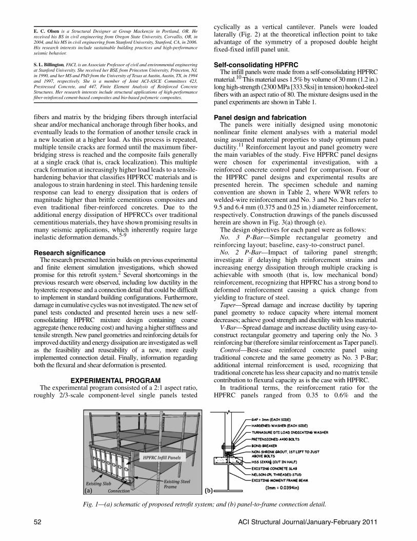
The retrofit system under investigation is shownschematically in Fig. 1(a). The system uses precast infill panelsmade from a ductile high-performance fiber-reinforcedconcrete (HPFRC) to add stiffness, strength, and energydissipation to deficient critical-use steel moment-frame
buildings. This system extends previous research on ductileinfill panels2 and panel-to-frame connection details.3 Theresearch presented herein evaluates a different HPFRCmaterial that contains coarse aggregate and has differentproperties, new reinforcement layouts, and a new connectiondetail. A different testing protocol and different instrumentationmethods were used as well. It is noted that this retrofit systemcould be considered for new design as a replaceable energy-dissipating fuse, which would be a topic for future research.
The retrofit system is designed with three objectives:1. Ease of installation to minimize disruption to current
facility operations;2. Protection of the steel frame and nonstructural systems
in a seismic event; and3. Simple, rapid repair after a seismic event to ensure
minimal disruption to continued facility operations.The panels are sized to be light and small enough to be
brought into a building by elevator and maneuvered by handor with a small lift. The panels are precast and use boltedconnections to limit disruptions associated with concreteplacement. Two panels are bolted together and to the existingframe beams to act as a single, fixed-end deep-beam flexuralelement. The panels are unlike traditional infill in that they arenot connected to adjacent panels or to the frame columns. Theconnections are designed to be reusable if panels, which actsacrificially, are damaged and need to be replaced after anearthquake. Because the infill panel system is modular,partially filled bays can be used to tailor global buildingresponse and to incorporate facility use constraints. Moreover,recognizing that hospitals undergo frequent reorganization offloor space use, with some effort and reanalysis, these infillscould be moved in the same way nonstructural partitions,which the panels might replace, could be moved.
High-performance fiber-reinforced cementitious composites
The high-performance concrete used in this research ispart of a class of materials referred to as high-performancefiber-reinforced cementitious composites (HPFRCCs),which include mixtures that do not contain coarse aggregate.HPFRCC is so named because of having an ultimate tensilestrength higher than its first cracking strength and theformation of multiple cracking during the inelasticdeformation process.4 When a tensile crack forms in anHPFRCC material, the fibers bridge the crack and prevent itsuncontrolled propagation. Stress is transferred between the
Title no. 108-S06
Cyclic Response of Precast High-PerformanceFiber-Reinforced Concrete Infill Panelsby E. C. Olsen and S. L. Billington
ACI Structural Journal/January-February 201152
cyclically as a vertical cantilever. Panels were loadedlaterally (Fig. 2) at the theoretical inflection point to takeadvantage of the symmetry of a proposed double heightfixed-fixed infill panel unit.
Self-consolidating HPFRCThe infill panels were made from a self-consolidating HPFRC
material.10 This material uses 1.5% by volume of 30 mm (1.2 in.)long high-strength (2300 MPa [333.5ksi] in tension) hooked-steelfibers with an aspect ratio of 80. The mixture designs used in thepanel experiments are shown in Table 1.
Panel design and fabricationThe panels were initially designed using monotonic
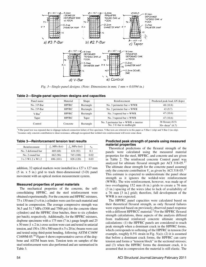
nonlinear finite element analyses with a material modelusing assumed material properties to study optimum panelductility.11 Reinforcement layout and panel geometry werethe main variables of the study. Five HPFRC panel designswere chosen for experimental investigation, with areinforced concrete control panel for comparison. Four ofthe HPFRC panel designs and experimental results arepresented herein. The specimen schedule and namingconvention are shown in Table 2, where WWR refers towelded-wire reinforcement and No. 3 and No. 2 bars refer to9.5 and 6.4 mm (0.375 and 0.25 in.) diameter reinforcement,respectively. Construction drawings of the panels discussedherein are shown in Fig. 3(a) through (e).
The design objectives for each panel were as follows:No. 3 P-Bar—Simple rectangular geometry and
reinforcing layout; baseline, easy-to-construct panel.No. 2 P-Bar—Impact of tailoring panel strength;
investigate if delaying high reinforcement strains andincreasing energy dissipation through multiple cracking isachievable with smooth (that is, low mechanical bond)reinforcement, recognizing that HPFRC has a strong bond todeformed reinforcement causing a quick change fromyielding to fracture of steel.
Taper—Spread damage and increase ductility by taperingpanel geometry to reduce capacity where internal momentdecreases; achieve good strength and ductility with less material.
V-Bar—Spread damage and increase ductility using easy-to-construct rectangular geometry and tapering only the No. 3reinforcing bar (therefore similar reinforcement as Taper panel).
Control—Best-case reinforced concrete panel usingtraditional concrete and the same geometry as No. 3 P-Bar;additional internal reinforcement is used, recognizing thattraditional concrete has less shear capacity and no matrix tensilecontribution to flexural capacity as is the case with HPFRC.
In traditional terms, the reinforcement ratio for theHPFRC panels ranged from 0.35 to 0.6% and the
E. C. Olsen is a Structural Designer at Group Mackenzie in Portland, OR. Hereceived his BS in civil engineering from Oregon State University, Corvallis, OR, in2004, and his MS in civil engineering from Stanford University, Stanford, CA, in 2006.His research interests include sustainable building practices and high-performanceseismic behavior.
S. L. Billington, FACI, is an Associate Professor of civil and environmental engineeringat Stanford University. She received her BSE from Princeton University, Princeton, NJ,in 1990, and her MS and PhD from the University of Texas at Austin, Austin, TX, in 1994and 1997, respectively. She is a member of Joint ACI-ASCE Committees 423,Prestressed Concrete, and 447, Finite Element Analysis of Reinforced ConcreteStructures. Her research interests include structural applications of high-performancefiber-reinforced cement-based composites and bio-based polymeric composites.
Fig. 1—(a) schematic of proposed retrofit system; and (b) panel-to-frame connection detail.
fibers and matrix by the bridging fibers through interfacialshear and/or mechanical anchorage through fiber hooks, andeventually leads to the formation of another tensile crack ina new location at a higher load. As this process is repeated,multiple tensile cracks are formed until the maximum fiber-bridging stress is reached and the composite fails generallyat a single crack (that is, crack localization). This multiplecrack formation at increasingly higher load leads to a tensile-hardening behavior that classifies HPFRCC materials and isanalogous to strain hardening in steel. This hardening tensileresponse can lead to energy dissipation that is orders ofmagnitude higher than brittle cementitious composites andeven traditional fiber-reinforced concretes. Due to theadditional energy dissipation of HPFRCCs over traditionalcementitious materials, they have shown promising results inmany seismic applications, which inherently require largeinelastic deformation demands.5-9
Research significanceThe research presented herein builds on previous experimental
and finite element simulation investigations, which showedpromise for this retrofit system.2 Several shortcomings in theprevious research were observed, including low ductility in thehysteretic response and a connection detail that could be difficultto implement in standard building configurations. Furthermore,damage in cumulative cycles was not investigated. The new set ofpanel tests conducted and presented herein uses a new self-consolidating HPFRC mixture design containing coarseaggregate (hence reducing cost) and having a higher stiffness andtensile strength. New panel geometries and reinforcing details forimproved ductility and energy dissipation are investigated as wellas the feasibility and reuseability of a new, more easilyimplemented connection detail. Finally, information regardingboth the flexural and shear deformation is presented.
EXPERIMENTAL PROGRAMThe experimental program consisted of a 2:1 aspect ratio,
roughly 2/3-scale component-level single panels tested
ACI Structural Journal/January-February 2011 53
reinforcement ratio for the concrete Control panel was 1%. Itis noted, however, that the strength of the variousreinforcements differ (Table 3).
The panels were cast flat in plywood forms and coveredwith plastic sheeting to cure for a minimum of 28 days, withthe exception of the V-Bar-2 panel, which was tested at 21 days.Cast acrylic cylindrical inserts were used to form the holesfor the connection through-bolts.
Threaded stud connection detailIn consultation with several practitioners, a connection
detail was designed using a proven construction techniqueand threaded welded studs (schematic shown in Fig. 1(b))with the following construction steps: (1) the existingconcrete slab is cored to expose the top flange of the framebeam; (2) a threaded stud longer than the depth of the hole iswelded within this hole to the frame beam; (3) the hole isfilled with grout; (4) a steel U-channel (half an HSS section)is bolted to the exposed threads of the stud; (5) an infill panelis lowered into place; (6) the tolerance between the base ofthe panel and the U-channel is filled with nonshrink grout;and (7) after the grout has cured, the panel is secured withpretensioned bolts. The retrofit sequence is similar to aproven construction technique referred to as “retrofit-upgrading to composite construction.” As this is a proventechnique, and for simplicity in the lab, in this research, thestuds were welded to a section of wide-flange beam prior tocasting the representative existing slab instead of casting theslab first and core-drilling.
To facilitate replaceability, the grout in the connection wasinstalled in two layers. The bottom layer of grout remainedintact after the top layer was chiseled after a test and wasreused six times. Bolt pretensioning was performed after thesecond layer of grout was allowed to cure for a minimum of36 hours. A calibrated torque wrench was used to torquethe 19 mm (3/4 in.) diameter ASTM A490 bolts to 178 kN(40 kips) each. Tension in the bolts was monitored usingdirect-tension-indicating washers.
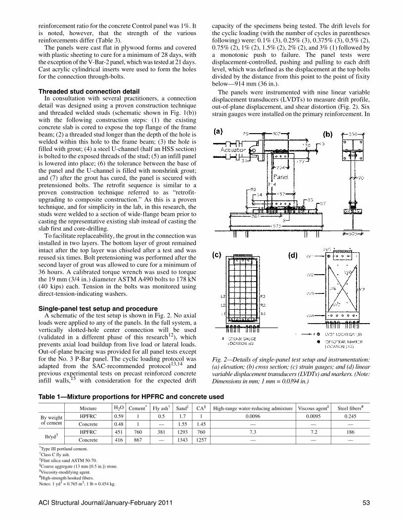
Single-panel test setup and procedureA schematic of the test setup is shown in Fig. 2. No axial
loads were applied to any of the panels. In the full system, avertically slotted-hole center connection will be used(validated in a different phase of this research12), whichprevents axial load buildup from live load or lateral loads.Out-of-plane bracing was provided for all panel tests exceptfor the No. 3 P-Bar panel. The cyclic loading protocol wasadapted from the SAC-recommended protocol13,14 andprevious experimental tests on precast reinforced concreteinfill walls,15 with consideration for the expected drift
capacity of the specimens being tested. The drift levels forthe cyclic loading (with the number of cycles in parenthesesfollowing) were: 0.1% (3), 0.25% (3), 0.375% (3), 0.5% (2),0.75% (2), 1% (2), 1.5% (2), 2% (2), and 3% (1) followed bya monotonic push to failure. The panel tests weredisplacement-controlled, pushing and pulling to each driftlevel, which was defined as the displacement at the top boltsdivided by the distance from this point to the point of fixitybelow—914 mm (36 in.).
The panels were instrumented with nine linear variabledisplacement transducers (LVDTs) to measure drift profile,out-of-plane displacement, and shear distortion (Fig. 2). Sixstrain gauges were installed on the primary reinforcement. In
Table 1—Mixture proportions for HPFRC and concrete used
Mixture H2O Cement* Fly ash† Sand‡ CA§ High-range water-reducing admixture Viscous agent|| Steel fibers#
By weight of cement
HPFRC 0.59 1 0.5 1.7 1 0.0096 0.0095 0.245
Concrete 0.48 1 — 1.55 1.45 — — —
lb/yd3HPFRC 451 760 381 1293 760 7.3 7.2 186
Concrete 416 867 — 1343 1257 — — —*Type III portland cement.†Class C fly ash.‡Flint silica sand ASTM 50-70.§Coarse aggregate (13 mm [0.5 in.]) stone.||Viscosity-modifying agent.#High-strength hooked fibers.Notes: 1 yd3 = 0.765 m3; 1 lb = 0.454 kg.
Fig. 2—Details of single-panel test setup and instrumentation:(a) elevation; (b) cross section; (c) strain gauges; and (d) linearvariable displacement transducers (LVDTs) and markers. (Note:Dimensions in mm; 1 mm = 0.0394 in.)
54 ACI Structural Journal/January-February 2011
addition, 32 optical markers were installed in a 127 x 127 mm(5 in. x 5 in.) grid to track three-dimensional (3-D) panelmovement with an optical motion measurement system.
Measured properties of panel materialsThe mechanical properties of the concrete, the self-
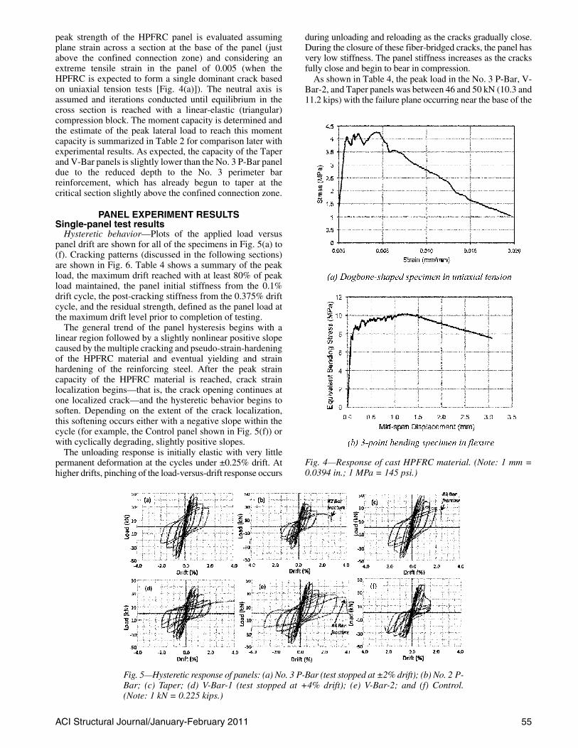
consolidating HPFRC, and the steel reinforcement wereobtained experimentally. For the concrete and HPFRC mixtures,75 x 150 mm (3 x 6 in.) cylinders were cast for each material andtested in compression. The average compressive strength was36.5 and 51.7 MPa (5300 and 7500 psi) for the concrete (threecylinders) and the HPFRC (four batches, three to six cylindersper batch), respectively. Additionally, for the HPFRC mixtures,dogbone specimens with a 175 mm (7 in.) gauge length and 25x 50 mm (1 x 2 in.) cross section were cast and tested in uniaxialtension, and 150 x 150 x 500 mm (6 x 5 x 20 in.) beams were castand tested using third-point bending, following ASTM C1609/C1609M-05.16 Figure 4 shows representative curves of the dog-bone and ASTM beam tests. Tension tests on samples of thesteel reinforcement were also performed and are summarized inTable 3.
Predicted peak strength of panels using measured material properties
Theoretical predictions of the flexural strength of thepanels were calculated using the measured materialproperties for the steel, HPFRC, and concrete and are givenin Table 2. The reinforced concrete Control panel wasanalyzed for ultimate flexural strength per ACI 318-05.17
The ultimate shear strength for the concrete panel assumedonly the concrete contribution Vc as given by ACI 318-05.17
This estimate is expected to underestimate the panel shearstrength as it ignores the welded-wire reinforcement(WWR). The wire reinforcement, however, was made up oftwo overlapping 152 mm (6 in.) grids to create a 76 mm(3 in.) spacing of the wires (due to lack of availability ofa 76 mm [3 in.] grid); therefore, full development of theWWR is not expected.
The HPFRC panel capacities were calculated based ontheir theoretical flexural strength, as only flexural failureswere expected based on previously observed panel responsewith a different HPFRCC material.2 For the HPFRC flexuralstrength calculations, three aspects of the analysis differedfrom traditional reinforced concrete ultimate strengthcalculations: (1) the HPFRC panels are considered to reachpeak strength when a dominant crack in the HPFRC forms,which corresponds to softening of the HPFRC in tension (forexample, roughly 0.5% strain in Fig. 5(a)); (2) it is assumedthat before a dominant crack forms, the HPFRC can carrytension and forms a “tension block” in the sectional stresses;and (3) when the HPFRC forms the dominant crack, it isassumed that in compression the material is still elastic. The
Table 2—Single-panel specimen designs and capacitiesPanel name Material Shape Reinforcement Predicted peak load, kN (kips)
No. 3 P-Bar HPFRC Rectangle No. 3 perimeter bar + WWR 48 (10.8)
No. 2 P-Bar HPFRC Rectangle No. 2 perimeter bar + WWR 43 (9.7)
V-Bar* HPFRC Rectangle No. 3 tapered bar + WWR 47 (10.6)
Taper HPFRC Taper No. 3 tapered bar + WWR 47 (10.6)
Control Concrete Rectangle No. 3 perimeter bar + WWR + interior No. 3 U-bar to midheight
38 flexure (8.5)30+ shear† (6.7)
*V-Bar panel test was repeated due to slippage-induced connection failure of first specimen. V-Bar tests are referred to in this paper as V-Bar-1 (slip) and V-Bar-2 (no-slip).†Assumes only concrete contribution to shear resistance, although recognized that welded-wire reinforcement will resist some shear.
Fig. 3—Single-panel designs. (Note: Dimensions in mm; 1 mm = 0.0394 in.)
Table 3—Reinforcement tension test results
Reinforcement fy ,MPa (ksi) fu ,MPa (ksi) εu
No. 3 deformed bar 469 (68) 634 (92) 0.1
No. 2 round bar 662 (96) 745 (108) 0.02
3 x 3 W1.2 x W1.2 696 (101) 828 (120) 0.03
ACI Structural Journal/January-February 2011 55
peak strength of the HPFRC panel is evaluated assumingplane strain across a section at the base of the panel (justabove the confined connection zone) and considering anextreme tensile strain in the panel of 0.005 (when theHPFRC is expected to form a single dominant crack basedon uniaxial tension tests [Fig. 4(a)]). The neutral axis isassumed and iterations conducted until equilibrium in thecross section is reached with a linear-elastic (triangular)compression block. The moment capacity is determined andthe estimate of the peak lateral load to reach this momentcapacity is summarized in Table 2 for comparison later withexperimental results. As expected, the capacity of the Taperand V-Bar panels is slightly lower than the No. 3 P-Bar paneldue to the reduced depth to the No. 3 perimeter barreinforcement, which has already begun to taper at thecritical section slightly above the confined connection zone.
PANEL EXPERIMENT RESULTSSingle-panel test results
Hysteretic behavior—Plots of the applied load versuspanel drift are shown for all of the specimens in Fig. 5(a) to(f). Cracking patterns (discussed in the following sections)are shown in Fig. 6. Table 4 shows a summary of the peakload, the maximum drift reached with at least 80% of peakload maintained, the panel initial stiffness from the 0.1%drift cycle, the post-cracking stiffness from the 0.375% driftcycle, and the residual strength, defined as the panel load atthe maximum drift level prior to completion of testing.
The general trend of the panel hysteresis begins with alinear region followed by a slightly nonlinear positive slopecaused by the multiple cracking and pseudo-strain-hardeningof the HPFRC material and eventual yielding and strainhardening of the reinforcing steel. After the peak straincapacity of the HPFRC material is reached, crack strainlocalization begins—that is, the crack opening continues atone localized crack—and the hysteretic behavior begins tosoften. Depending on the extent of the crack localization,this softening occurs either with a negative slope within thecycle (for example, the Control panel shown in Fig. 5(f)) orwith cyclically degrading, slightly positive slopes.
The unloading response is initially elastic with very littlepermanent deformation at the cycles under ±0.25% drift. Athigher drifts, pinching of the load-versus-drift response occurs
Fig. 5—Hysteretic response of panels: (a) No. 3 P-Bar (test stopped at ±2% drift); (b) No. 2 P-Bar; (c) Taper; (d) V-Bar-1 (test stopped at +4% drift); (e) V-Bar-2; and (f) Control.(Note: 1 kN = 0.225 kips.)
during unloading and reloading as the cracks gradually close.During the closure of these fiber-bridged cracks, the panel hasvery low stiffness. The panel stiffness increases as the cracksfully close and begin to bear in compression.
As shown in Table 4, the peak load in the No. 3 P-Bar, V-Bar-2, and Taper panels was between 46 and 50 kN (10.3 and11.2 kips) with the failure plane occurring near the base of the
Fig. 4—Response of cast HPFRC material. (Note: 1 mm =0.0394 in.; 1 MPa = 145 psi.)
ACI Structural Journal/January-February 201156
panel. As expected, the gradual tapering of thereinforcement, either by tapering the panel shape or bytapering the reinforcing bar within the rectangular panel,only slightly reduced the final panel capacity. The V-Bar-1panel had a lower capacity due to significant slipping in theconnection region, leading to a connection failure that isdiscussed in the following. The No. 2 P-Bar panel was weakerdue to the smaller amount of reinforcement used. The Controlpanel with traditional concrete was the only panel to fail inshear and had the lowest capacity of all of the panels. The lowcapacity is attributed to both the concrete strength relative tothat of the HPFRC and the susceptibility of this panel(geometry, loading, and concrete material) to fail in shearrather than flexure. Had the concrete been of equivalentstrength to the HPFRC—that is, 51.7 MPa (7500 psi)—thepanel would still have been expected to fail in shear. Anincrease in flexural and shear capacity (the Vc component) of5 and 17%, respectively, would have been expected using thepreviously described prediction approach.
The maximum drift at which 80% of the peak load wasmaintained was 1% for most panels. The exceptions were theNo. 2 P-Bar panel, which was less ductile, and the Controlpanel, which maintained 80% of its negative direction peakload up to 1.5% drift after abrupt shear failure had occurredin the positive direction at 1% drift. The panel initial stiffnesswas similar for all of the tests. The post-cracking stiffness forall of the panels showed more variation. The V-Bar-1 panelwas less stiff than the V-Bar-2 panel because it experiencedconnection slippage. The Taper panel had similar initial andpost-cracking stiffness as the Control panel despite itstapered cross section. The similar stiffness is attributed to anincreased stiffness provided by the HPFRC, which containsan extra 1.5% by volume of steel for the fibers relative totraditional concrete. Panel residual strength was typicallybetween 40 and 50% of peak strength at the end of each test,except for the Control panel, which showed a low residualstrength of 16% due to the abrupt shear failure.
The general trend for the cyclic strength degradation—thatis, the difference in strength between the first and secondtime the drift level was reached during testing—was similarfor all of the panels. As expected, cyclic degradation wasnegligible for all panels in their elastic range. By the 1.0%drift, cyclic strength degradation was typically 15 to 20% inall of the panels. The panels that were able to maintain higherresidual strengths after softening (crack localization) showedless cyclic degradation as well at their post-localization driftlevels (for example, Taper, V-Bar-2, and—to some extent—the No. 3 P-Bar, although this test was stopped after onecycle at 2% drift).
Experimental versus predicted strength—The peakloads measured in the HPFRC panels with No. 3reinforcement that did not experience connection slippage
were within 4% of those predicted by the theoreticalcalculations. The average strength of the No. 2 P-Barpanel was 18% lower than predicted. The larger differencebetween the actual and predicted capacities for the No. 2 P-Bar panel is attributed to the actual tensile block beingsmaller than assumed for the No. 2 P-Bar panel, which useda smooth rod as opposed to the deformed No. 3 bar that waspresent in the rest of the HPFRC panels. The assumed tensileblock for the HPFRC was taken as the full tension zone fromthe extreme fiber to the neutral axis of the cross section. Withdeformed bars, the size of the multiple cracks in HPFRC willbe better controlled than with a smooth rod. Therefore,whereas the assumption of the full tension zone carryingtension in the HPFRC seems to work well for the panels withdeformed reinforcement, it leads to an overprediction instrength for panels with only smooth reinforcement. If thelower 70% of the tensile region is assumed to carry tensionin the HPFRC, the strength prediction for the No. 2 P-Barpanel would be approximately 35 kN (7.9 kips), similar towhat was experimentally measured. It is noted that reasonablevariations—5 to 10%—in the No. 2 reinforcement strengthcould not account for the observed 20% difference in panelstrength. Although the method used herein predicted thestrength of these HPFRC panels well, further research isrecommended to validate the use of an HPFRC tension blockin predicting reinforced HPFRC component strengths.
For the Control panel, a shear failure was observed at alateral load of 41.4 kN (9.3 kips). The predicted strengthfrom concrete alone considering a nominal concrete shearstrength of 2 times the square root of the compressivestrength gave a prediction of 30 kN (6.7 kips). It cantherefore be assumed that the WWR present, which if fullydeveloped would be expected to contribute an additional 31 kN(6.9 kips) of additional shear strength, is only able to contributeapproximately 11 kN (2.5 kips) of shear resistance prior toshear failure in the panel.
Cracking, yielding, and modes of failure—All of theHPFRC panels failed in a flexural mode, whereas theControl panel failed in shear. Sketches of the crackingpropagation for each specimen are shown in Fig. 6. For theHPFRC panels, the dark crack indicates the location offlexural crack localization, which became the failure plane.Reinforcing bar fracture occurred at this location in allpanels except the No. 3 P-Bar panel, which was stopped at2% drift due to out-of-plane movement, and the V-Bar-1panel, which failed in the connection region due to slippage.The failure plane for the HPFRC panels occurred toward thebase of the panel. The Control panel of reinforced concretefailed in shear with large X-shaped cracks indicative of acyclic-shear failure.
The Taper panel was designed to help distribute the damagethrough the height of the panel as compared to the No. 3 P-Bar
Table 4—Single-panel cyclic test results summary
Panel
Peak load, kN (kips)Maximum drift
with >80% of peak load, %Stiffness at ±0.1% drift,
kN/mm (kip/in.)Stiffness at ±0.375%drift, kN/mm (kip/in.)
Residual strength, kN (kips)[% of peak]
(+) (–) (+) (–) (+) (–) (+) (–) (+) (–)
No. 3 P-Bar 49.8 (11.2) 48.0 (10.8) 1.0 1.0 16.5 (94.3) 16.5 (94.3) 11.7 (66.9) 10.7 (61.2) 28.0 (6.3) [56%] 24.5 (5.5) [51%]
No. 2 P-Bar 36.5 (8.2) 34.3 (7.7) 1.0 0.66 15.1 (86.3) 15.9 (90.9) 10.5 (60.0) 8.6 (49.1) 15.6 (3.5) [43%] 13.8 (3.1) [40%]
Taper 48.9 (11) 46.7 (10.5) 1.0 1.0 15.6 (89.2) 15.6 (89.2) 10.3 (58.9) 8.2 (46.9) 27.1 (6.1) [55%] 24.9 (5.6) [53%]
V-Bar-1 40.9 (9.2) 38.7 (8.7) 1.0 1.0 16.1 (92.0) 15.2 (86.9) 9.8 (56.0) 7.7 (44.0) 20.0 (4.5) [49%] 16.0 (3.6) [41%]
V-Bar-2 46.3 (10.4) 46.3 (10.4) 1.0 1.0 16.5 (94.3) 16.5 (94.3) 10.5 (60.0) 9.8 (56.0) 24.0 (5.4) [52%] 21.8 (4.9) [47%]
Control 41.4 (9.3) 38.3 (8.6) 1.0 1.5 15.1 (86.3) 15.1 (86.3) 10.3 (58.9) 8.4 (48.0) 6.7 (1.5) [16%] 16.5 (3.7) [43%]

ACI Structural Journal/January-February 2011 57
panel, for example, which had a constant panel capacity alongits height. More distributed damage in the Taper panel wasobserved both in the cracking pattern (Fig. 6) and in comparingthe measured steel strains. The longitudinal steel reinforcementreached strains of 0.009 and 0.042 at the middle gauge (GaugeL2 shown in Fig. 2(c)) in the No. 3 P-Bar and Taper panels,respectively. Higher up, (Gauge L3 shown in Fig. 2(c)), the steelin the No. 3 P-Bar panel reached a strain of 0.0026 comparedwith 0.0044 in the Taper panel.
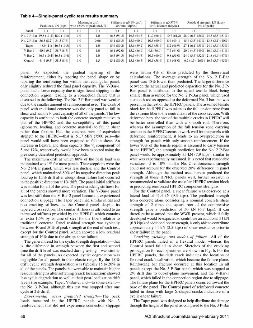
Energy dissipation—Figure 7 compares the hystereticenergy dissipation of the first load-displacement cycle foreach specimen at different drift levels. The energydissipation from the panels is a result of the multiplecracking and tensile-carrying capacity of the HPFRCmaterial, as well as the yielding of the main reinforcing steel.The panels that exhibited the greatest energy dissipationcorresponded to those that showed the greatest crackingdistribution and reinforcement strain gauge strain readings:the No. 3 P-Bar, Taper, and V-Bar-2 panels. The V-Bar-1panel also showed relatively high energy dissipation untilthe connection slippage began at 1% drift, forming amajor crack in the connection region and preventing furthermultiple cracking in the HPFRC. The Control and No. 2 P-Bar panels showed the least energy dissipation. The Controlpanel, being traditional reinforced concrete, was notexpected to dissipate as much energy as the reinforcedHPFRC panels and again failed in shear at 1% drift. The No. 2P-Bar panel showed the least crack distribution during the test(Fig. 6), which correlates to the low calculated energydissipation. Furthermore, the reinforcement was high strengthwith low ductility (Table 3) and hence was not expected todissipate significant energy.
Figure 8(a) further compares the energy dissipation ofeach panel at different drift levels relative to an equivalentreinforced concrete panel assumed to have an elastoplasticresponse—that is, a parallelogram of initial stiffness and
peak expected strength from a similarly reinforced concretepanel. An example of this is the Taper panel shown in Fig. 8(b)).This comparison is similar in concept to the relative energydissipation ratio used to evaluate precast moment frames forseismic regions (for example, ACI ITG 1.1-0118) with theexception of the peak value for the parallelogram being onefor a reinforced concrete panel rather than an HPFRC panel.The energy dissipation of the experimental panel wascalculated as the area of the hysteretic loop (load-displacement response) of the first cycle at a given driftlevel. The equivalent reinforced concrete panel’s energydissipation was calculated as the area of an elastoplasticresponse where the initial stiffness was taken as thatmeasured in the reinforced concrete Control panel. Theultimate strength was calculated assuming the samereinforcement details as the panel to which it is being
Fig. 6—Crack propagation in panels.
Fig. 7—Hysteretic energy dissipation in first full cycle ateach drift level. (Note: 1 kN-mm = 0.00885 kip-in.)
58 ACI Structural Journal/January-February 2011
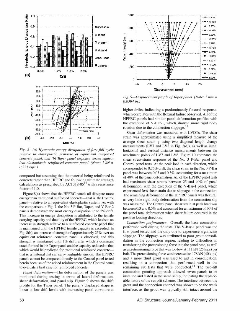
higher drifts, indicating a predominantly flexural response,which correlates with the flexural failure observed. All of theHPFRC panels had similar panel deformation profiles withthe exception of V-Bar-1, which showed more rigid bodyrotation due to the connection slippage.11
Shear deformation was measured with LVDTs. The shearstrain was approximated using a simplified measure of theaverage shear strain γ using two diagonal length changemeasurements (LV7 and LV8 in Fig. 2(d)), as well as initialhorizontal and vertical distance measurements between theattachment points of LV7 and LV8. Figure 10 compares theshear stress-strain response of the No. 3 P-Bar panel andControl panel tests. At the peak load in each direction, whichcorresponded to 0.75% drift, the shear strain in the No. 3 P-Barpanel was between 0.03 and 0.3%, accounting for a maximumof 40% of the panel deformation. All of the HPFRC panel testshad maximum shear strains between 25 and 40% of paneldeformation, with the exception of the V-Bar-1 panel, whichexperienced less shear strain due to slippage in the connection.The remaining deformation in the HPFRC panels was flexural,as very little rigid-body deformation from the connection slipwas measured. The Control panel shear strain at peak load wasbetween 0.3 and 0.5% and accounted for a maximum of 50% ofthe panel total deformation when shear failure occurred in thepositive loading direction.
Connection performance—Overall, the base connectionperformed well during the tests. The V-Bar-1 panel was thefirst panel tested and the only one to experience significantslippage. The slippage was attributed to poor grout consoli-dation in the connection region, leading to difficulties intransferring the pretensioning force into the panel base, as wellas a pretensioning force that was too low at 111 kN (25 kips) perbolt. The pretensioning force was increased to 178 kN (40 kips)and a more fluid grout was used to aid in consolidation,resulting in a connection that performed well in theremaining six tests that were conducted.11 The two-liftconnection grouting approach allowed seven panels to beinstalled and tested in the same setup, indicating the replace-able nature of the retrofit scheme. The interface between thegrout and the connection channel was shown to be the weakinterface, as the grout was typically still intact around the
compared but assuming that the material being reinforced isconcrete rather than HPFRC and following ultimate strengthcalculations as prescribed by ACI 318-0517 with a resistancefactor of 1.0.
Figure 8(a) shows that the HPFRC panels all dissipate moreenergy than traditional reinforced concrete—that is, the Controlpanel—relative to an equivalent elastoplastic system. As withthe comparison in Fig. 7, the No. 3 P-Bar, Taper, and V-Bar-2panels demonstrate the most energy dissipation up to 2% drift.This increase in energy dissipation is attributed to the tensilecarrying capacity and ductility of the HPFRC, which leads to anincrease in strength relative to a reinforced concrete panel thatis maintained until the HPFRC tensile capacity is exceeded. InFig. 8(b), an increase of strength of approximately 25% over anequivalent reinforced concrete panel is observed, and thisstrength is maintained until 1% drift, after which a dominantcrack formed in the Taper panel and the capacity reduced to thatwhich would be predicted for traditional reinforced concrete—that is, a material that can carry negligible tension. The HPFRCpanels cannot be compared directly to the Control panel testedherein because of the added reinforcement in the Control panelto evaluate a best case for reinforced concrete.
Panel deformation—The deformation of the panels wasmonitored during testing in terms of lateral deformation,shear deformation, and panel slip. Figure 9 shows the driftprofile for the Taper panel. The panel’s displaced shape islinear at low drift levels with increasing panel curvature at
Fig. 8—(a) Hysteretic energy dissipation of first full cyclerelative to elastoplastic response of equivalent reinforcedconcrete panel; and (b) Taper panel response versus equiva-lent elastoplastic reinforced concrete panel. (Note: 1 kN =0.225 kips.)
Fig. 9—Displacement profile of Taper panel. (Note: 1 mm =0.0394 in.)

ACI Structural Journal/January-February 2011 59
bottom of the removed panel. No cracking was observed inthe lightly reinforced slab during panel testing.
Slip and out-of-plane displacement—Panel slip wasmonitored with the optical motion measurement system.The V-Bar-1 panel showed a panel base slip ofapproximately 20 mm (0.79 in.). All other panels exhibiteda panel slip of less than 1.5 mm (0.06 in.). The slip in the V-Bar-1 panel was confirmed by the reinforcing steel straingauge readings. In the V-Bar-1 panel, Gauge L1 reached apeak strain of 0.003, whereas Gauge L1 in the V-Bar-2 panelreached a strain of 0.0172.11
Whereas the test setup prevented large out-of-planedisplacements, small amounts (for example, 10 mm [0.39 in.])were possible. Out-of-plane displacement was measured withboth an LVDT and the optical motion measurement system.An out-of-plane movement at peak panel load of less than5 mm (0.02 in.) was observed for all of the tests.
PANEL COMPARISONSEffect of reinforcement details
The strength of the No. 2 P-Bar panel was lower than theNo. 3 P-Bar panel due to a smaller provided reinforcingresistance. Because the No. 2 P-Bar panel was smooth, it wasof interest to observe if allowing slippage could increase driftcapacity and delay reinforcing bar fracture, given that theHPFRC material bonds so tightly to deformed reinforcement.However, the drift capacity at peak load, energy dissipation athigher drift levels, amount of multiple cracking spreadthroughout the panel, and residual strength measured as apercentage of peak were all less in the No. 2 P-Bar panelthan in the No. 3 P-Bar panel. These decreases inperformance were attributed to the measured strain capacityof the No. 2 bar being much less than the No. 3 bar (refer toTable 3) as well as the low reinforcement ratio, which led tothe rapid yielding of the reinforcement when cracking began,thus localizing the strain and further limiting the ability of thesmooth bar to facilitate cracking distribution.
A comparison of the effect of the reinforcing details of theNo. 3 P-Bar and V-Bar-2 panels shows that tapering thepanel capacity with reinforcement alone can spread paneldamage, increase energy dissipation, and increase driftcapacity. The load-drift response of the two panels wasremarkably similar; the V-Bar-2 panel exhibited slightlyhigher energy dissipation at larger drifts. The main benefit ofthe V-Bar-2 panel is its peak drift capacity. The No. 3 P-Barpanel load noticeably dropped off by approximately 16%,whereas the V-Bar panel dropped off only slightly(approximately 6%) at 1.0% drift. The V-Bar panel hadslightly less capacity, which was expected as the depth of thetension reinforcement tapered down. Similar and extensivereinforcement yielding was observed from the strain gaugereadings for both panels.11
Effect of panel shapeTapering both the reinforcement and the panel itself
(Taper panel) was found to improve panel performance overthe rectangular geometry with perimeter reinforcement. Fora given drift, more curvature and reinforcing bar strain isexpected and was observed in the Taper panel. Comparing theTaper panel to the No. 3 P-Bar panel, for example, the Taperpanel showed the same strength, more energy dissipation,crack distribution higher up the panel, higher drift capacity atpeak load, and more gradual softening behavior. The Taperpanel maintained the same or slightly higher residual strength
Fig. 10—Shear response of Control and No. 3 P-Bar panels.(Note: 1 kN = 0.225 kips.)
relative to its peak strength compared to all of the rectangularpanels. Whereas all of the panels exhibited significantreinforcement yielding, measured strains were higher in thehigher strain gauges in the Taper panel than in all of therectangular panels. The Taper panel perimeter reinforcing barfractured at a lower drift level (2.5%) than the V-Bar-2 panel(3.75%) with a similar reinforcement layout. The earlierfracture in the Taper panel is attributed to the Taper panel’slower flexural stiffness.
Effect of panel materialThe Control panel was approximately 25% weaker than
the HPFRC panels with No. 3 perimeter bars. As discussedpreviously, this lower strength is partly attributed to thelower strength of the concrete relative to the HPFRC andpartly due to the inability of a concrete panel of thisgeometry, reinforcement, and loading to resist shear as wellas one with HPFRC, which inherently has a higher shearcapacity due to the composite’s tensile load-carryingcapacity. The Control panel failed in shear at midheight at +1%drift and just after –2% drift. The No. 3 P-Bar panel had a higherpeak strength until approximately 1% drift, beyond which thestrength reduced to just under that of the Control panel. Thehigher strength of the No. 3 P-Bar panel is attributed to thecontribution of the reinforced HPFRC material, whichdiminishes once a crack localizes and the panel behavesmore like a reinforced concrete panel in flexure—that is,HPFRC carrying compression and reinforcement carryingtension. In addition to increasing the strength of the panel,the reinforced HPFRC also helped avoid a brittle shearfailure and exhibited a gradual rather than abrupt reductionin capacity at higher drifts. Whereas the Control panel showedsevere spalling, the No. 3 P-Bar panel with HPFRC experiencedonly minor flaking of the material in compression.
CONCLUSIONSSingle-panel component experiments for a proposed
retrofit technique were conducted. The goal of theexperiments was to observe the hysteretic response andfailure modes of infill panels using a self-consolidatingHPFRC material, as well as to verify a proposed connectiondetail. Different panel reinforcement details, panelgeometry, and panel cement-based materials were used toachieve varying objectives of high ductility, optimal materialusage, and ease of construction.

ACI Structural Journal/January-February 201160
The results from the single-panel cyclic tests reportedherein show that variation in strength, hysteretic behavior,energy dissipation, and failure mechanism can be achievedthrough reinforcement detailing, panel material, andgeometry. The effect of the reinforced HPFRC materialcompared to the reinforced concrete Control panel wasprimarily to transform the failure mode from a brittle shearfailure to a more gradual flexural failure. At drift levelsbeyond 2%, an average increase of 50% in energydissipation was also achieved with the HPFRC panelsrelative to the reinforced concrete Control panel. Themultiple cracking phenomenon of the HPFRC panelscorrelated to the amount of energy dissipation seen in thetests. The panels that exhibited the largest distribution ofcracking showed the most energy dissipation. At peak load,the deformation of the HPFRC panels was between 60 and75% flexural deformation and between 25 and 40% sheardeformation with negligible panel base slip contribution.
The first panel tested (V-Bar-1) exhibited connectionslippage during testing, which led to premature panel failureinitiated in the connection region. In this test, slippage wasattributed to poor grout consolidation and low boltpretensioning. In subsequent tests, a more flowable groutwas used, along with a higher bolt pretensioning force. Withthese adjustments, the connection region behaved very welland could be reused up to six times, thus verifying thepotential reusability of this proposed connection detail. Out-of-plane deformations were determined to be small enoughto not significantly affect panel performance.
Using a low reinforcement ratio (No. 2 (6.4 mm [0.25 in.]P-Bar panel) with smooth reinforcement led to early cracklocalization at the base and prevented significant distributionof cracking and thus energy dissipation. Whereas the use ofsmooth reinforcement was anticipated to assist in delayingyielding and fracture (and thus distribute cracking), thereinforcement used in this panel was too small and had toolow a strain capacity to adequately assess crack distribution.
Tapering of the reinforcement or panel itself was shown toimprove panel performance in terms of drift capacity andenergy dissipation. The tapering attempted to lower thecapacity of the panel along its height as the demand wasreduced and led to a better distribution of damage throughoutthe panel, delayed crack localization at the panel base, andhelped use more of the high-performance material.
Hand predictions of reinforced HPFRC panel capacityassuming a full tensile block—that is, from the extreme tensilefiber to the neutral axis—of HPFRC contributing to thecapacity was found to predict panel capacity well in the case ofHPFRC reinforced with deformed reinforcement. With smoothreinforcement, a smaller tensile block leads to a better estimateof the capacity due to less multiple cracking and earlier cracklocalization (that is, opening of a dominant crack). A detailedstudy of the strength of reinforced HPFRC is needed to providesimple, transparent design and analysis guidelines.
This retrofit scheme has recently been further investigatedthrough double-height panel tests to validate all connectiondetails and out-of-plane behavior of a full-height panelsystem.12 In addition, the response of a two-story single-bayframe infilled with HPFRC panels has recently beenevaluated using hybrid simulation. All of these tests are in-plane loading experiments, and further research is needed onsystem response to 3-D loading to understand the impact ofout-of-plane movement on system performance.
ACKNOWLEDGMENTSThe research described herein was sponsored by the National Science
Foundation under Grant No. 0530383 in the Network for EarthquakeEngineering Simulation Research (NEESR) program. This study wasconducted by the first author as a visiting researcher at the University ofMichigan (UM) in Ann Arbor. Support from the UM Civil & EnvironmentalEngineering Department, Stanford University, and material and labordonations from Nelson Stud Welding are gratefully acknowledged, alongwith the significant contributions of UM research assistants R. Lequesneand W. Cheng. The assistance of technicians R. Spence and R. Fischer fromUM is also greatly appreciated. Industry participation in the development ofthe connection details was contributed by D. Mar, J. Malley, and W. Holmes.
REFERENCES1. Senate Bill 1953, “Hospital Facilities Seismic Safety Act,”
Chapter 740, Statues of 1994, California Legislature, 1994.2. Kesner, K. E., and Billington, S. L., “Investigation of Infill Panels
Made from Engineered Cementitious Composites for SeismicStrengthening and Retrofit,” Journal of Structural Engineering, ASCE,V. 131, No. 11, 2005, pp. 1712-1720.
3. Kesner, K. E., and Billington, S. L., “Experimental Response ofPrecast Infill Panel Connections and Panels Made with DFRCC,” Journalof Advanced Concrete Technology, V. 1, No. 3, 2003, pp. 1-7.
4. Naaman, A. E., “Strain Hardening and Deflection Hardening FiberReinforced Cement Composites,” International Workshop on High-Performance Fiber-Reinforced Cement Composites, A. E. Naaman and H.W. Reinhardt, eds., France, 2003, pp. 95-113.
5. Fischer, G., and Li, V., “Effect of Matrix Ductility on DeformationBehavior of Steel-Reinforced ECC Flexural Members under ReversedCyclic Loading Conditions,” ACI Structural Journal, V. 99, No. 6, Nov.-Dec. 2002, pp. 781-790.
6. Billington, S. L., and Yoon, J. K., “Cyclic Response of Precast BridgeColumns with Ductile Fiber-Reinforced Concrete,” Journal of BridgeEngineering, ASCE, V. 9, No. 4, 2004, pp. 353-363.
7. Canbolat, B. A.; Parra-Montesinos, G. J.; and Wight, J. K.,“Experimental Study on Seismic Behavior of High-PerformanceFiber-Reinforced Cement Composite Coupling Beams,” ACI StructuralJournal, V. 102, No. 1, Jan.-Feb. 2005, pp. 159-166.
8. Parra-Montesinos, G. J.; Peterfreund, S. W.; and Chao, S.-H.,“Highly Damage-Tolerant Beam-Column Joints through Use of High-Performance Fiber-Reinforced Cement Composites,” ACI StructuralJournal, V. 102, No. 3, May-June 2005, pp. 487-495.
9. Kyriakides, M. A., and Billington, S. L., “Seismic Retrofit ofMasonry-Infilled Non-Ductile Reinforced Concrete Frames UsingSprayable ECC,” Proceedings of the 14th World Conference on EarthquakeEngineering (14WCEE), Beijing, China, Oct. 2008.
10. Liao, W.-C.; Chao, S.-H.; Park, S.-Y.; and Naaman, A. E., “Self-Consolidating High-Performance Fiber-Reinforced Concrete(SCHPFRC)— Preliminary Investigation,” Report UMCEE 06-02,Department of Civil and Environmental Engineering, University ofMichigan, Ann Arbor, MI, 2006, 76 pp.
11. Olsen, E. C., and Billington, S. L., “Cyclic Behavior of Energy-Absorbent Precast Infill Panels for Seismic Retrofit of Steel Frame Buildings UsingSelf-Compacting High-Performance Fiber-Reinforced CementitiousComposites,” Technical Report No. 164, John E. Blume Center forEarthquake Engineering, Stanford University, Stanford, CA, 2009, 231 pp.
12. Hanson, J. V., “Cyclic Testing of a Ductile Fiber-ReinforcedConcrete Infill Panel System for Seismic Retrofitting of Steel Frames,”Engineer degree thesis, Stanford University, Stanford, CA, 2008, 201 pp.
13. SAC/BD-97/02, “Protocol for Fabrication, Inspection, Testing andDocumentation of Beam-Column Connection Tests and OtherExperimental Specimens,” Report No. SAC/BD-97-02, SAC JointVenture, Sacramento, CA, 1997.
14. AISC, “Seismic Provisions for Structural Steel Buildings I,”American Institute of Steel Construction, Chicago, IL, 2005, 310 pp.
15. Tong, X.; Hajjar, J. F.; Schultz, A. E.; and Shield, C. K., “CyclicBehavior of Steel Frame Structures with Composite Reinforced Infill Wallsand Partially Restrained Connections,” Journal of Constructional SteelResearch, V. 61, No. 4, 2005, pp. 531-552.
16. ASTM C1609/C1609M-05, “Standard Test Method for FlexuralPerformance for Fiber-Reinforced Concrete (Using Beam with Third-PointLoading),” ASTM International, West Conshohocken, PA, 2005, 8 pp.
17. ACI Committee 318, “Building Code Requirements for StructuralConcrete (ACI 318-05) and Commentary (318R-05),” American ConcreteInstitute, Farmington Hills, MI, 2005, 430 pp.
18. ACI Innovation Task Group 1 and Collaborators, “Acceptance Criteriafor Moment Frames Based on Structural Testing (T1.1-01) and Commentary(T1.1R-01),” American Concrete Institute, Farmington Hills, MI, 2001, 10 pp.