cta-31L corvette lower control arm kit - Yahoo · jack stands under the frame. ... Place a floor...
3
` Global West Suspension 655 South Lincoln Ave. San Bernardino, CA. 92408 PHONE: 877-470-2975 FAX: 909-890-0703 globalwest.net Part # CTA-31L --- Corvette front tubular lower control arm kit --- 1963-81 Global West tubular control arms are pre- assembled for easy installation. New installation hardware is also included. Parts list: • Fully assembled right lower arm • Fully assembled left lower arm • 4 – 7/16 grade 8 bolts 2-1/4 inches long fine thread • 4 – 7/16 lock washers • 2 – 9/16 grade 8 bolts 2-1/8 inches long machined fine thread • 2 – 9/16 stovelock nuts fine thread • 4 – 9/16 thick washers 1. Raise the front of the vehicle up and install jack stands under the frame. Remove the wheels. 2. Remove the shocks. 3. Use an inside spring compressor and compress the spring, removing tension on the lower control arm. 4. Place a floor jack under the lower control arm and lift the lower arm up so the upper control arm bump stop is no longer touching the arm. Remove the cotter pin and lower ball joint nut. Using a pickle fork or other ball joint removing tool, separate the lower ball joint from the spindle. The spindle will drop off the lower ball joint once the ball joint releases. 5. Swing the spindle out of the way. Using a small 2x4 piece of wood, raise the upper arm and place the wood between the frame and control arm. This will keep the assembly out of the way. 6. Lower the control arm and slide the spring out of the frame pocket.
Transcript of cta-31L corvette lower control arm kit - Yahoo · jack stands under the frame. ... Place a floor...
`
Global West Suspension655 South Lincoln Ave. San Bernardino, CA. 92408
PHONE: 877-470-2975 FAX: 909-890-0703globalwest.net
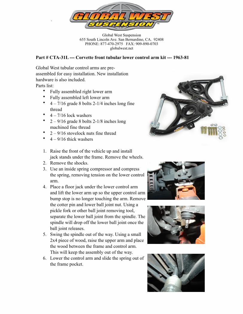
Part # CTA-31L --- Corvette front tubular lower control arm kit --- 1963-81
Global West tubular control arms are pre-assembled for easy installation. New installation hardware is also included. Parts list:
• Fully assembled right lower arm• Fully assembled left lower arm• 4 – 7/16 grade 8 bolts 2-1/4 inches long fine
thread• 4 – 7/16 lock washers• 2 – 9/16 grade 8 bolts 2-1/8 inches long
machined fine thread• 2 – 9/16 stovelock nuts fine thread• 4 – 9/16 thick washers
1. Raise the front of the vehicle up and install jack stands under the frame. Remove the wheels.
2. Remove the shocks.3. Use an inside spring compressor and compress
the spring, removing tension on the lower control arm.
4. Place a floor jack under the lower control arm and lift the lower arm up so the upper control arm bump stop is no longer touching the arm. Remove the cotter pin and lower ball joint nut. Using a pickle fork or other ball joint removing tool, separate the lower ball joint from the spindle. The spindle will drop off the lower ball joint once the ball joint releases.
5. Swing the spindle out of the way. Using a small 2x4 piece of wood, raise the upper arm and place the wood between the frame and control arm. This will keep the assembly out of the way.
6. Lower the control arm and slide the spring out of the frame pocket.

7. Remove the lower control arm from the frame.
8. Install the new lower control arm with new hardware supplied in your kit. The 9/16 bolt supplied in the kit requires using two thick washers, one on the top of the frame and one next to the shaft. Place one thick washer on a 9/16 bolt, install from the top down through the frame.
9. Install the 7/16 bolts towards the front of the shaft using new bolts and washers. Reuse the factory-threaded block.
10. Tighten down the bolts and torque the front bolts to 65-foot-pounds and torque the rear 9/16 bolt to 90 foot-pounds.
11. Install the spring next. The lower control arm has a spring cushion. It will be red or black. The
spring cushion is designed to
index the spring in the lower control arm by rotating it in the base. Index the spring in the frame first; rotate the spring cushion so the spring indexes.
Use a floor jack under the control arm and raise the arm up high enough so the lower ball joint slips into the spindle. Remove the wood block between the frame and the arm. Lower the arm down onto the ball joint. Install the ball joint nut and cotter pin. Torque the nut to 70 foot-pounds.
12. Remove the spring compressor from inside the spring. 13. Once the compressor is removed re-install the shocks. 14. Proceed to the other side and follow the same procedure.

15. After completion lubricate the lower ball joints and install the wheels. Note: The lower control arm bushings come pre-lubricated.