CSTAR P802M Installation Guide v.04
28
-
Upload
hector-garcia -
Category
Documents
-
view
66 -
download
1
description
Guía (en inglés) para la instalación de la CSTAR P802M
Transcript of CSTAR P802M Installation Guide v.04

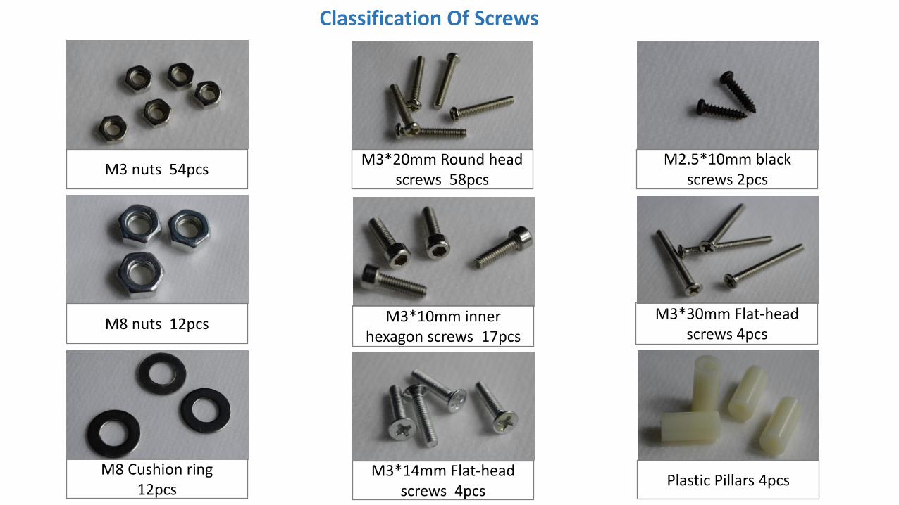
M3 nuts 54pcsM3*20mm Round head
screws 58pcsM2.5*10mm black
screws 2pcs
M3*10mm inner hexagon screws 17pcs
M8 nuts 12pcs
M8 Cushion ring12pcs
Plastic Pillars 4pcsM3*14mm Flat-head
screws 4pcs
M3*30mm Flat-head screws 4pcs
Classification Of Screws

M4*15mm Round head cross screws 12pcs
M4*8mm Round head cross screws 12pcs
Compression springs*4Thumb nuts*4
Classification Of Screws
M3*25mm Round head screws 7pcs
M3*22mm Round head screws 4pcs
(Use for locking bearings on extruder)

Step 1 Assemble Y-axis Motor
M3*10mm inner hexagon screws*4
Y-axis motor support
Y-axis motor
M3*2mm jackscrew
Synchronous pulley
Fit the synchronous pulley on the motor, Locking with M3*2mm jackscrew.
As the picture, Put Y-axis motor on <Y-axis motor support> , locking with Four M3*10mm screws.
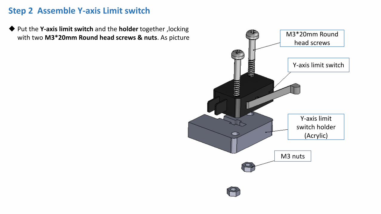
Step 2 Assemble Y-axis Limit switch
Put the Y-axis limit switch and the holder together ,locking with two M3*20mm Round head screws & nuts. As picture M3*20mm Round
head screws
Y-axis limit switch
Y-axis limit switch holder
(Acrylic)
M3 nuts

Step 3 Assemble Base Frame Holder_Back
Y-axis motor assembly
Sliding rod Restriction*2
M3*20mm screws
Y-axis limit switch assembly
Y-axis motor holder
Base frame holder_Back
M3 nuts
As the picture, put two of the Sliding rod Restriction in front of the base frame holder (back). locking with two M3*20mm Round head screws & nuts.
Put the limit switch and holder assembly on the base frame holder, locking with one M3*20mm Round head screw & nut.
Put Y-axis motor holder on base frame holder ,locking with one M3*20mm Round head screw & nut.
Put Y-axis motor assembly on base frame holder, locking with three M3*20mm Round head screws & nuts.

Step 4 Assemble Base Frame Holder_Front
Sliding rod Restriction*2
M3*20mm Round head Screws & nuts
Y-axis belt pulley wheel assembly
Base Frame Holder_Front
As the picture, put two of the Sliding rod Restriction in front of the base frame holder _front. locking with two M3*20mm Round head screws & nuts.
Put Y-axis belt pulley wheel assembly behind the base frame holder, Locking with two M3*20mm Round head screws & nuts.

Aluminium plateM3*30mm screws*4 Heat bed M3 nuts
Bed frame
Bearing*3Thumb nuts*4
M4*15mm Round head
cross screws *12
Compression springs*4
M3 nuts Fixed part
Step 5 Assemble Heat Bed Frame
Firstly fixed the Bed Frame and M3 nuts fixed parts together with M3*20mm. As picture below.
As the picture, put Aluminium plate and heat bed together, locking with four M3*30mm screws & nuts.
Put three bearings under the bed frame, locking with twelve M4*15 Round head cross screws.
Put four compression spring between heat bed and the bed frame. Next Top four thumb nuts under the bed frame.
M3*20mm Round head cross screwsBelt clip
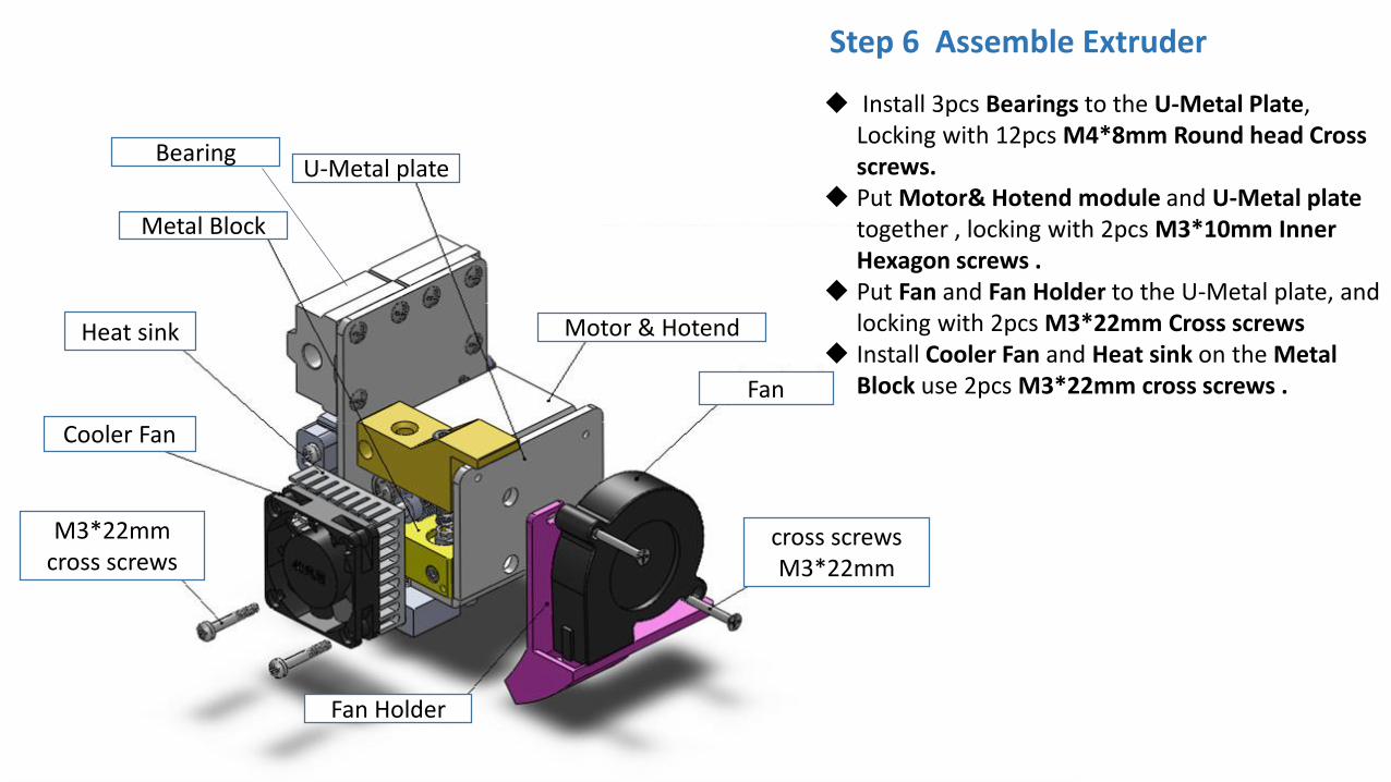
Bearing
Motor & Hotend
Fan Holder
Fan
cross screws M3*22mm
U-Metal plate
Step 6 Assemble Extruder
Cooler Fan
Heat sink
Metal Block
M3*22mm cross screws
Install 3pcs Bearings to the U-Metal Plate, Locking with 12pcs M4*8mm Round head Cross screws.
Put Motor& Hotend module and U-Metal plate together , locking with 2pcs M3*10mm Inner Hexagon screws .
Put Fan and Fan Holder to the U-Metal plate, and locking with 2pcs M3*22mm Cross screws
Install Cooler Fan and Heat sink on the Metal Block use 2pcs M3*22mm cross screws .
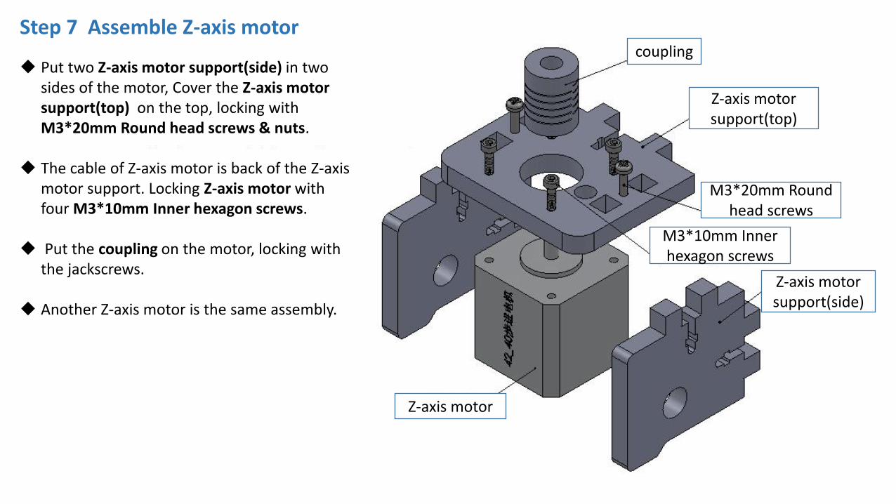
Step 7 Assemble Z-axis motorcoupling
M3*20mm Round head screws
M3*10mm Inner hexagon screws
Z-axis motor support(side)
Z-axis motor support(top)
Z-axis motor
Put two Z-axis motor support(side) in two sides of the motor, Cover the Z-axis motor support(top) on the top, locking with M3*20mm Round head screws & nuts.
The cable of Z-axis motor is back of the Z-axis motor support. Locking Z-axis motor with four M3*10mm Inner hexagon screws.
Put the coupling on the motor, locking with the jackscrews.
Another Z-axis motor is the same assembly.

Z-axis motor assembly
Bottom plate
M3 nuts
M3*20mm Round head screws
As the picture, Put the two Z-axis motors assembly on the left and right side of the Bottom plate, locking with three M3*20mm screws & nuts.
Step 8 Assemble Z-axis

Step 9 Assemble Side plate
As the picture, Put the two Side plate on the left and right side of the Bottom plate , locking with four M3*20mm screws & nuts.
Side plate
M3*20mm Round head screws

Step 10 Assemble Top plate & Junction PlateSliding rod restriction
Junction Plate
Top plate
M3*20mm Round head screws
As the picture, Put the Top plate on Side Plate, locking with four M3*20mm screws & nuts.
Put the two Junction Plate on the top of the Side plate ,locking with four M3*20 screws & nuts.
Put two sliding rod restriction on the top of left and right sides. Locking with one M3*20mm Round head screw & nut each.

Step 11 Install LCD display
M3 nuts
LCD display assembly
M3*25mm Flat head screws
Framework (top half)
Put the LCD display on the top of the Top plate ,locking with three M3*25mm flat_head screws &nuts

Step 12 Install Z-axis Limit switch
Put the Z-axis limit switch on the left side of Bottom plate, Locking with two M3*20mm Round head screws and nuts.
M3*20mm Round head screw & nut
Z-axis limit switch

Step 13 Install Power supply
Put Power supply on the right of the side plate , locking with three M3*14mm Flat_head screws and nuts.
M3*14mm Flat_head screw
Side plate
Power supply

Control Board
M3 Nuts*8
Plastic Pillars*4
M3*25mm Flat_headScrews *4
Side plate
Step 14 Install PCBA Control Board
Install Control Board as picture , locking with Four M3*25mm Flat head screws + 4pcs Plastic pillars + 4pcs M3 nuts

Step 15 Install Base frame holder_Back
Base frame holder_back
M3*16mm Round head
screws*4
Put the Base frame holder_back back of Side plate, locking with four M3*20mm Round head screw
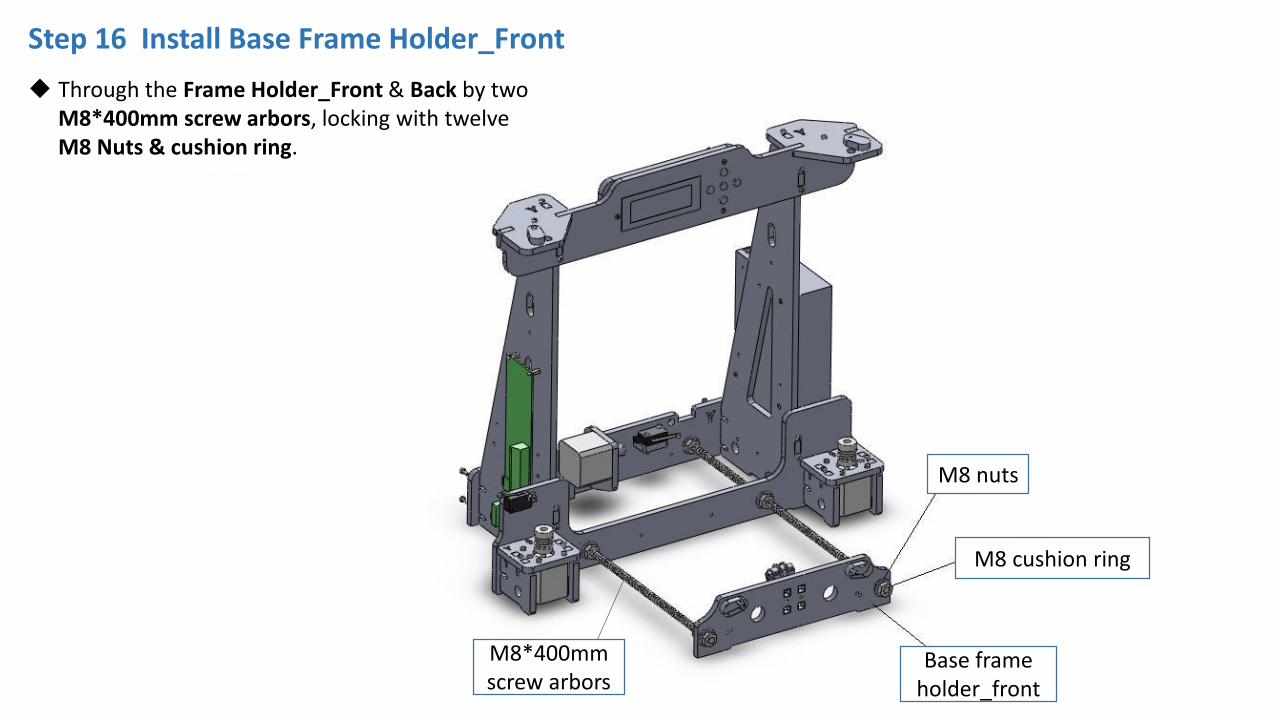
Step 16 Install Base Frame Holder_Front
M8 cushion ring
M8*400mm screw arbors
Base frame holder_front
M8 nuts
Through the Frame Holder_Front & Back by two M8*400mm screw arbors, locking with twelve M8 Nuts & cushion ring.

Step 17 Instal Platform Assembly
Platform assembly
M8*380mm sliding rod*2
Sliding rod RestrictionThe 1pcs bearing
are on this side
Attention: Put the 1pcs bearing on the hotbed on the left side , and put the hotbed wires on back side .
As the picture , through the platform on the base by two of M8*380mm Sliding rod. Fix both end by Sliding rod restriction

Acrylic Bed frame
Timing beltBelt clip*2
M3*20mm Round head
screws &nuts
Y-axis belt pulley wheel assembly
Synchronous pulley
Step 18 Instal Y-axis Timing belt
As the picture, Lock one end of the timing belt in belt clip , the other end through the Y-axis motor and belt pulley wheel on the base frame holder. Then tense the belt and lock in the other belt clip with M3*20mm Round head screws & nuts.

Sliding rod restriction
M8*380mm Sliding rod
Coupling
M8*345mm screw arbor
X-axis Pulley mount
X-axis Motor mount
Step 19 Instal X-axis Motor & Pulley mount
Put X-axis motor on X-axis motor mount. Locking with three M3*10mm Inner hexagon screws.
Through the X-axis motor mount & pulley mount by M8*380mm sliding rod & M8*345mm screw arbor. As picture
Limit the top of sliding rod with sliding rod restriction, connect the bottom of screw arbors with couplings , locking jackscrew in coupling.
X-axis Motor

Step 20 Assemble X-axis
X-axis motor mount
X-axis pulley mount
M8*443mm sliding rod
Extruder assembly
X-axis limit switch
Through the X-axis motor mount & Pulley mount and Extruder assembly using two M8*443mm sliding rods, as the picture.
Put X-axis limit switch on the X-axis motor mount, locking with two M2.5*10mm screws (small black screw)

Step 21 Instal X-axis Timing BeltX-axis timing belt
Tighten one end of the Timing Belt to the Belt clip with Nylon cable ties. The other end through the X-axis pulley & motor ,then tighten another end of the belt to the another Belt clip with Nylon cable ties . as picture below
Belt clip
Nylon cable ties

Step 22 Control Board Wiring Diagram
The method of connecting wire is as picture
Wire the X Y Z axis Limit switches “COM” and “NO” these 2 ends , as pictures
!NOTE!: The wires connected to POWER SUPPLY andHETBED must be AWG14 or thicker one.
The red wire above

Step 23 AC Power Connector Wiring Diagram
Connect Power cable as the picture (Right)
Note: There are different voltages in different country. Please select the appropriate voltage by switch before power on. As the picture below.
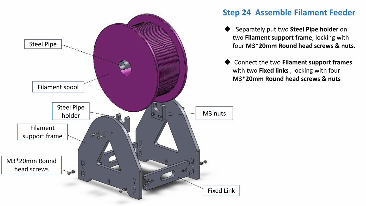
Filament spool
Filament support frame
Fixed Link
Steel Pipe
M3*20mm Round head screws
M3 nutsSteel Pipe
holder
Step 24 Assemble Filament Feeder
Separately put two Steel Pipe holder on two Filament support frame, locking with four M3*20mm Round head screws & nuts.
Connect the two Filament support frames with two Fixed links , locking with four M3*20mm Round head screws & nuts

Installation Finished