Installation v 2_4 ipasolink 400
98
NEC IPASOLINK 400 INSTALLATION AND PROVISIONING © Pekka Linna NEC Finland Oy 2012
description
ipasolink 400
Transcript of Installation v 2_4 ipasolink 400

NEC IPASOLINK 400
INSTALLATION AND PROVISIONING
© Pekka Linna NEC Finland Oy 2012

2
CONTENTS
INTRODUCTION ...................................................................................................................... 6
PRODUCT DESCRIPTION ..................................................................................................... 6
IPASOLINK 400 ........................................................................................................................ 7
COMPATIBLE OUTDOOR UNITS ........................................................................................ 8
NHG ..................................................................................................................................... 8
NHG2 ..................................................................................................................................... 8
IHG ..................................................................................................................................... 9
BLOCK DIAGRAMS ................................................................................................................ 9
AVAILABLE CONFIGURATIONS ....................................................................................... 11
UNPROTECTED HOP ....................................................................................................... 11
PROTECTED CONFIGURATIONS ................................................................................. 11
ETHERNET PROTECTION USING 2+0 OR XPIC 1+0 .............................................................. 11
RADIO TRAFFIC AGGREGATION ............................................................................................. 11
CONFIGURATION DIAGRAMS ................................................................................................. 12
ASYMMETRICAL HOPS ........................................................................................................... 15
EXTERNAL CONNECTION SPEED AND RADIO PATH CAPACITY .......................... 15
IPASOLINK CAPACITY ............................................................................................................. 16
QOS AND OVERPROVISIONING ....................................................................................... 18
ADAPTIVE MODULATION ................................................................................................... 18
MAIN SPECIFICATIONS ...................................................................................................... 20
IDU CONFIGURATIONS ....................................................................................................... 22
PDH-INTERFACES ............................................................................................................ 24
MANAGEMENT AND AUXILIARY INTERFACES ........................................................................ 24

3
INDOOR UNIT CONFIGURATIONS ................................................................................... 25
ORDERING CODES .............................................................................................................. 26
PREINSTALLED LICENSES ............................................................................................... 26
SAFETY ISSUES .................................................................................................................... 26
OPEN WAVEGUIDE AND OPTICAL CONNECTORS .................................................................. 26
AVOID THE FRONT OF THE ANTENNA .................................................................................... 26
RADIATION MONITORING DEVICES ............................................................................ 27
SAFETY DISTANCE FOR THE PUBLIC EXPOSURE .................................................. 27
INDOOR UNIT INSTALLATION .......................................................................................... 28
VENTILATION ..................................................................................................................... 28
ENVIRONMENTAL REQUIREMENTS ........................................................................................ 28
POWER CONNECTION ............................................................................................................ 29
ASSEMBLING THE POWER CABLE .............................................................................. 29
ETHERNET CABLE CONNECTIONS ............................................................................. 30
PDH CONNECTIONS ............................................................................................................... 30
ODU INSTALLATION ............................................................................................................ 30
6 GHZ ODU WITH STANDARD WAVEGUIDE ............................................................... 31
SEPARATE INSTALLATION OF 7 AND 13 GHZ DIRECT MOUNT ODU...................................... 32
DIRECT MOUNT INSTALLATION ................................................................................... 32
ODU CABLE INSTALLATION .................................................................................................... 34
CABLE CONNECTORS ..................................................................................................... 35
GROUNDING ...................................................................................................................... 35
Grounding outside .................................................................................................................................... 35
Grounding in the shelter .......................................................................................................................... 36
Suitable grounding connectors ............................................................................................................... 36

4
IDU AND CABLE LABELLING ................................................................................................... 36
OVERVOLTAGE PROTECTION ................................................................................................ 36
LOCAL MANAGEMENT ....................................................................................................... 37
MANAGEMENT TOOL ....................................................................................................... 37
RECOMMENDED BROWSER ................................................................................................... 37
LOCAL CONNECTION ............................................................................................................. 37
REMOTE LOGIN USING THE BROWSER .................................................................................. 38
LOGIN WINDOW ................................................................................................................ 38
MAIN PAGE – MENU AND CURRENT STATUS ......................................................................... 39
NAMING OF THE IDU AND MODEMS ....................................................................................... 39
BASIC SETTINGS .................................................................................................................. 39
PROVISIONING CLEAR .................................................................................................... 40
NETWORK MANAGEMENT (NMS) SETTINGS ............................................................ 47
MODEM SETTINGS ........................................................................................................... 51
SYNCHRONIZATION SETTING ............................................................................................... 52
DATE AND TIME SETTING ....................................................................................................... 55
NETWORK MANAGEMENT SECURITY SETTINGS ................................................................... 56
ANTENNA ALIGNMENT ....................................................................................................... 61
MANAGEMENT NETWORK ................................................................................................ 63
DCN OVER PDH/SDH .............................................................................................................. 65
MANAGEMENT USING METRO ETHERNET VPLS SERVICE .................................. 65
PROVISIONING PDH ............................................................................................................ 66
ETHERNET SETTINGS ........................................................................................................ 69
VLAN SETTINGS ..................................................................................................................... 70
BRIDGE MODES (802.1Q AND 802.1AD) .............................................................................. 72
5
SAMPLE VLAN SETTINGS ....................................................................................................... 73
QOS SETTINGS ..................................................................................................................... 76
TRAFFIC CLASSIFICATION PRINCIPLES .................................................................... 76
SAMPLE QOS POLICY...................................................................................................... 79
QOS SETTINGS – CLASSIFY AND INGRESS POLICING .......................................... 80
PORT QOS SETTINGS ............................................................................................................. 82
QOS SETTINGS SUMMARY ..................................................................................................... 84
COPYING SETTINGS FROM ONE IDU TO ANOTHER .................................................. 85
PRECONFIGURATION FILES ............................................................................................. 90
KNOWN PROBLEMS ............................................................................................................ 91
APPENDIX A. RECEIVER THRESHOLD DATA .............................................................. 92
APPENDIX B. MC-A4/16E1-A MDR68-CONNECTOR PIN LAYOUT .......................... 95
APPENDIX C. MC-A4 D-SUB-44 CONNECTOR PIN LAYOUT ................................... 96
APPENDIX D. QUICK INSTALLATION GUIDE/CHECK LIST ...................................... 97
Version 2.4 2012-09-20

6
INTRODUCTION
This document describes the installation and provisioning of NEC iPasolink 400 microwave transmission
equipment. The information is based on the IDU firmware version 3.00.37. Additional information is
available in the manual iPasolink 400 Installation, Operation and Maintenance (NWD-115474-05E).
iPasolink 200 and iPasolink 1000 are very similar; however, there are some differences due to hardware
configurations. Reference is made to the appropriate equipment manuals.
Appendix D contains a quick provisioning guide. The quick guide is based on the configuration files that
have to be copied to the equipment before using the quick setup. The configuration files have to be
customised for each customer’s basic HW configuration. Rebooting of the equipment with traffic
interruption will take place when the configuration file is copied to the equipment.
PRODUCT DESCRIPTION
The microwave transmission family (iPasolink 100/200, 400 and 1000) enables full duplex wireless
transmission between two modems at a rate of over 400 Mbit/s per direction. With XPIC and radio channel
aggregation, over 800 Mbit/s per radio channel can be achived.
The interfaces are based on the Ethernet, PDH and SDH standards.
Frequency division duplex is used. A pair of channels separated by certain duplex spacing is required.
iPasolink uses licensed frequency bands. The frequency administration provides interference-free channels
to different operators based on frequency planning: transmitter powers and antenna sizes etc are
specified. Alternatively, in some countries, the operator may be given a block allocation of spectrum and
the operator is then responsible for the proper frequency planning inside the block. In any case, the correct
operation is only possible with proper frequency planning so that adequate signal-to-interference margin is
available. Moreover, the microwave hop has to be planned according to current ITU-R methods in order to
ensure sufficient margin against fading.
NEC iPasolink uses the traditional split mount installation method: indoor unit (IDU), coaxial cable, outdoor
unit (ODU) and antenna. Different products of the iPasolink 100/200/400/1000 family may interface over
the air with certain limitations regarding maximum modulation. Fully outdoor versions (iPasolink AX, SX and
EX) are also available but are not over-the-air compatible with iPasolink 100, 200, 400 or 1000.
The indoor unit contains the baseband interfaces (nxE1, STM-1, FE or GbE) as well as modems, a power
supply (or supplies) and a control unit with NMS interfaces. The interconnecting cable uses intermediate
frequencies below 400 MHz for the data and control signals. It feeds the power to the outdoor unit at -48

7
V. The frequency bands available cover the standard bands 6 to 42 GHz. Microwave signals do not
penetrate buildings, vegetation or terrain nor bend around obstacles. Therefore the antenna has to be
placed on top of a tall building or on a tall tower or mast in order to provide free line-of-sight connection to
the opposite end.
IPASOLINK 400
This guide is based on the middle-sized member of the family, the iPasolink 400. It may contain up to four
(4) modems. Each modem can provide Ethernet L2 capacity 10 to 400 Mbit/s or PDH/SDH capacity up to
152 x E1 or 2 x STM-1 or various combinations. The actual capacity depends on the available channel width
and available signal to noise/interference ratio and the fade margin required to fulfil the availability targets.
In the most basic configuration only one of the four slots contains a modem. The main card has always
FE/GbE and E1 interfaces. The other slots may contain additional GbE, SDH or E1 interfaces or modems. In
addition, TDM over packet (PWE), Synchronous Ethernet etc. options are available.
The highest capacities (400 Mbit/s) require access to a frequency band with 55 to 60 MHz channel spacing,
typically such channels are available in the upper 6 GHz, 18 GHz, 32 GHz or 38 GHz bands. On such bands
where the maximum spacing is only 27.5 or 28 MHz, the maximum capacity per modem is limited to about
200 Mbit/s. If necessary, two modems can share the same channel by using orthogonal polarizations and
XPIC (cross-polarization interference canceller). In such a setup the maximum combined capacity is about
400 Mbit/s (27.5 or 28 MHz channels) or about 800 Mbit/s (55 or 56 MHz channels).
The element management connection is based on Ethernet/IP transmission. All elements should be
connected to an EMS (PNMSj or MS5000). Within each iPasolink cluster the management traffic is carried
internally and separated from the customer traffic. A dedicated gateway connection (NMS port) to the
management data communication network (DCN) is typically used at the “root” element of the cluster.
Another solution is to use a traffic interface at the root element (in-band connection to root element).
Figure 1. iPasolink 400 indoor unit (IDU).

8
In the unit in Fig. 1 two modems (left) and a GbE interface card (right) have been installed. The unused slot
is covered by a blank cover. In the lower part are (from the left): the main card, a power supply, an unused
power supply slot and the fan unit.
COMPATIBLE OUTDOOR UNITS
Figure 2. Compatible outdoor units.
Indoor units: IHG is the latest version, silver coloured. NHG2 is white on the higher bands and beige on the
lowers bands whereas the NHG and the 6 to 11 GHz NGH2 look identical.
Any two IDUs belonging to the iPasolink 100/200/400/1000 family can be connected over the air. Note that
iPasolink IDU cannot interface to a previous generation (e.g. PASOLINK NEO) IDU. However, older
generation ODUs can be reused with iPasolink IDUs. There are certain limitations presented below.
NHG
NHG does not support 256QAM or higher modulations; only 128QAM and lower modulations formats are
guaranteed to work properly. When used with iPasolink IDU the FW version of the NHG ODU has to be 3.50
or later. This upgraded ODU will not work with a Pasolink NEO IDU any more - unless FW is downgraded
back to 3.50.
NHG2
NHG2 FW 4.06 works only with an iPasolink IDU. Earlier FW versions than 4.06 work only with Pasolink NEO
IDU. The recommended NHG2 FW version is 5.08 or later, which are compatible with both Pasolink NEO

9
and iPasolink indoor units. NHG2 upgrade to level 5.08 from lower level than 4.90.0 is a two-step upgrade:
to level 4.90.0 first and then to level 5.08 or later.
IHG
IHG FW version should be 5.08 or later. IHG will then work with iPasolink and PASOLINK NEO.
BLOCK DIAGRAMS
The block diagram of iPasolink 400 Indoor Unit (IDU) is presented in Figure 3. The Outdoor Unit (ODU) is
described in Figure 4.
The IDU main card has a separate TDM switch and a packet network L2 switch. It supports natively both
circuit-switched TDM as well as packet-switched Ethernet transport modes. In addition the equipment
supports the ”TDM-over-Ethernet” mode when equipped with the PWE option.
The modulator part of the modem generates an intermediate frequency signal. It is modulated by the
digital baseband signals and sent up to the ODU. The demodulator part demodulates the intermediate
frequency signal coming down from the ODU.
The demodulator includes an adaptive equalizer which repairs the linear distortions (poor amplitude and
phase response of the channel) caused by multipath fading. It also includes a FEC (Forward Error Correction
code) which is able to correct bit errors even very close to the threshold receive level. The system is almost
error-free until very close to the threshold and the transition to outage is within a couple of dB.
It is possible to equip the iPasolink 400 and 1000 IDUs with two redundant power supplies. Interruption of
one -48V supply voltage or a fault in one power supply unit will not cause any traffic interruption. Note:
iPasolink 100/200 has two independent connections to external -48V voltage but does not contain a
redundant power supply unit.

10
Figure 3. iPasolink 400 IDU, block diagram.
Figure 4. IHG ODU, block diagram.
The Outdoor Unit (ODU) generates the final microwave signal using the IF signal from the IDU by
upconverting it one or two times (MIX). The output of the mixer is band-pass filtered (BPF) in order to
remove the unwanted mixing products and then power amplified (PA). In the receive direction there is a
Low Noise Amplifier (LNA) and a mixer/filter which generates the receive direction IF signal. The local
oscillator (LO) frequencies are synthesized and controlled by the Control unit (CTRL). Transmitter output
power is fine-controlled automatically according to the modulation used and optionally based on the
remote end received power (Automatic Transmit Power Control, ATPC).
Both the modem in the IDU and the ODU contain a duplexer (DUP, MPX) which combines the different
directions of transmission to the same cable connector. The ODU power supply uses the DC voltage (-48V)

11
connected to the single coaxial cable centre conductor. The ODU can be mounted up to 500 metres from
the IDU, when a high-quality (e.g. ½ inch low-loss) coaxial cable is used.
AVAILABLE CONFIGURATIONS
UNPROTECTED HOP
The most basic configuration is a 1+0 or unprotected hop between a pair of modems. A single iPasolink 400
IDU can have up to four (4) 1+0 connections to separate sites. In this maximum configuration four ODUs,
four antennas and four coaxial cables are needed together with one IDU and four modems.
PROTECTED CONFIGURATIONS
If the requirement for the service restoration time after a failure is very strict, there is no time to go to the
site to replace the failed unit. In some cases the Service Level Agreement (SLA) does not allow any service
interruption caused by equipment failures. In such cases a 1+1 protected hop can be used. Both
transmitters may be transmitting always, each using a separate channel (frequency diversity, twin path).
Alternatively the spare transmitter is activated and the main transmitter muted only during a transmitter
failure (hot standby). In both solutions the receivers and demodulators are always activated and the IDU
will select the better (less bit errors) signal for processing.
The reliability (MTBF) of iPasolink is very high, which means that the traffic MTBF of the 1+1-solution is
extremely high, provided that the first fault is repaired within a reasonable time (within a few days). The
main disadvantage - in addition to double equipment cost - of the 1+1-solution is that the number of
equipment faults will double compared to the 1+0 solution. As an expample: if the equipment MTBF of a
1+0 hop is 100 years, then the MTBF of a 1+1 hop is approximately 50 years. But the traffic MTBF of a 1+1
hop could be perhaps 1000 years, however, depending on the fault repair time. Another disadvantage of
the 1+1 twin path solution is that only 50% of available capacity per MHz is in actual use.
ETHERNET PROTECTION USING 2+0 OR XPIC 1+0
A more cost efficient solution to protect Ethernet connections is to use 2+0 (or XPIC 1+0) on the same hop.
The traffic is then distributed between two modems and ODUs. The normal capacity could be as high as
800 Mbit/s. In case of a failure of an ODU, as an example, the traffic may still use the other ODU at 400
Mbit/s.
It is possible to use a dual-polarised antenna with XPIC (Fig. 7). It should be noted that the partial
equipment protection using “1+0 XPIC” is not fully automatic: the non-functional side transmitter has to be
muted manually in order to operate the remaining side at full speed.
RADIO TRAFFIC AGGREGATION
Radio traffic aggregation (RTA) to a single external Ethernet external interface can be done at L2 or L1 level.
12
When using L2 aggregation, a single “stream” is not distributed to the two radio paths due to the known
limitation of the standard LAG method. Several streams (e.g. different MAC DA or SA) are needed in order
to use the full capacity.
The more advanced NEC proprietary L1 aggregation (Physical RTA, PRTA) method will create a genuine
combined Ethernet port towards the air and even a single Ethernet stream can use the full capacity.
Modem versions supporting L1 aggregation PRTA: see Table 6 below (page 24).
CONFIGURATION DIAGRAMS
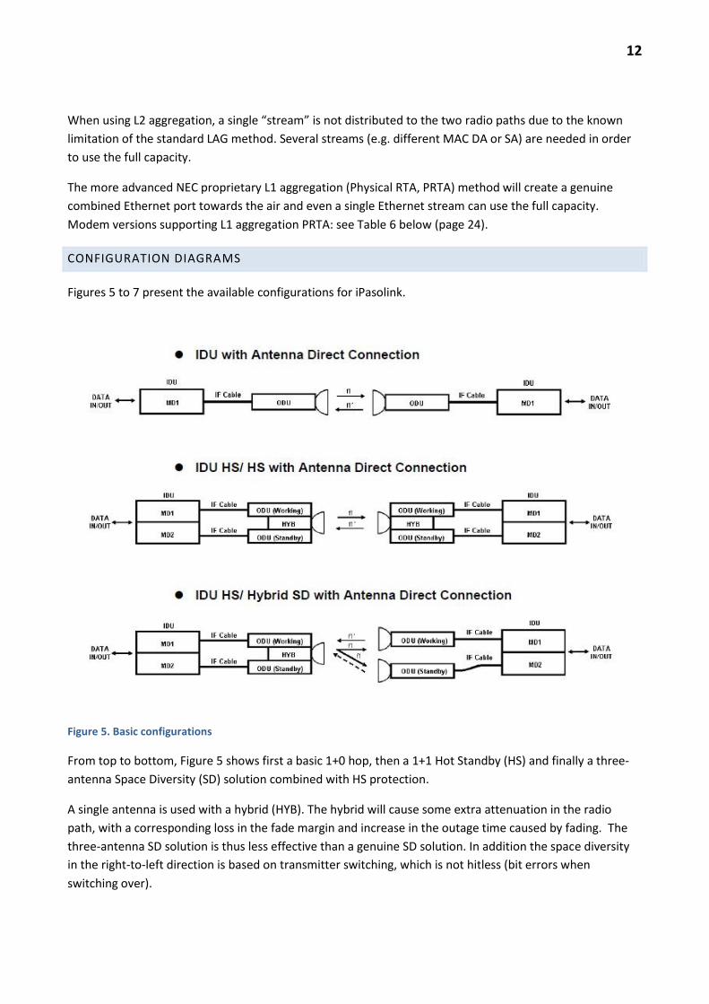
Figures 5 to 7 present the available configurations for iPasolink.
Figure 5. Basic configurations
From top to bottom, Figure 5 shows first a basic 1+0 hop, then a 1+1 Hot Standby (HS) and finally a three-
antenna Space Diversity (SD) solution combined with HS protection.
A single antenna is used with a hybrid (HYB). The hybrid will cause some extra attenuation in the radio
path, with a corresponding loss in the fade margin and increase in the outage time caused by fading. The
three-antenna SD solution is thus less effective than a genuine SD solution. In addition the space diversity
in the right-to-left direction is based on transmitter switching, which is not hitless (bit errors when
switching over).

13
Figure 6. Additional configurations.
Figure 6 shows on the top a HS/SD solution using four antennas per hop. This is the best solution for long
hops: no loss of fade margin and switching is hitless in both directions.
The middle solution is 2+0, i.e. two working channels and no protection channel. However, considering
Ethernet traffic, 2+0 has some protection against a single equipment failure. Two separate radio channels
are required and when properly configured, when a fault occurs in an ODU or modem, L2 or L1 aggregated
packet traffic is automatically rerouted to the remaining working channel. Half of the packet capacity is still
available when one channel is faulty.
The bottom configuration in Fig. 6 is an aggregation node solution: separate sites connected to a single IDU
and a single Ethernet connector. One or more radio channels will be needed depending on the angular
spacing of antenna directions. In principle 4+0 without XPIC can be even used on a single hop but then four
radio channels are needed.
It is possible to use less radio channels on the same hop using XPIC and crossed polarizations (Figure 7
below). The modems are interconnected using XPIC cables. The system calculates the original signals using
all available information, i.e. both IF signals are connected to both modems.

14
Figure 7. XPIC configurations.
Figure 7, top, shows a basic XPIC 1+0 (could be called XPIC 2+0 as well). It uses a single channel pair, two
polarizations and four modems per hop over a single antenna per site. Double capacity is achieved without
using any extra spectrum. Note: 1+0 XPIC partial protection for aggregated packet traffic is not automatic.
When a fault occurs preventing the use of XPIC, the interfering transmitter has to be manually muted
(either locally or remotely) in order to remove the interference and allow maximum speed operation of the
remaining modem.
15
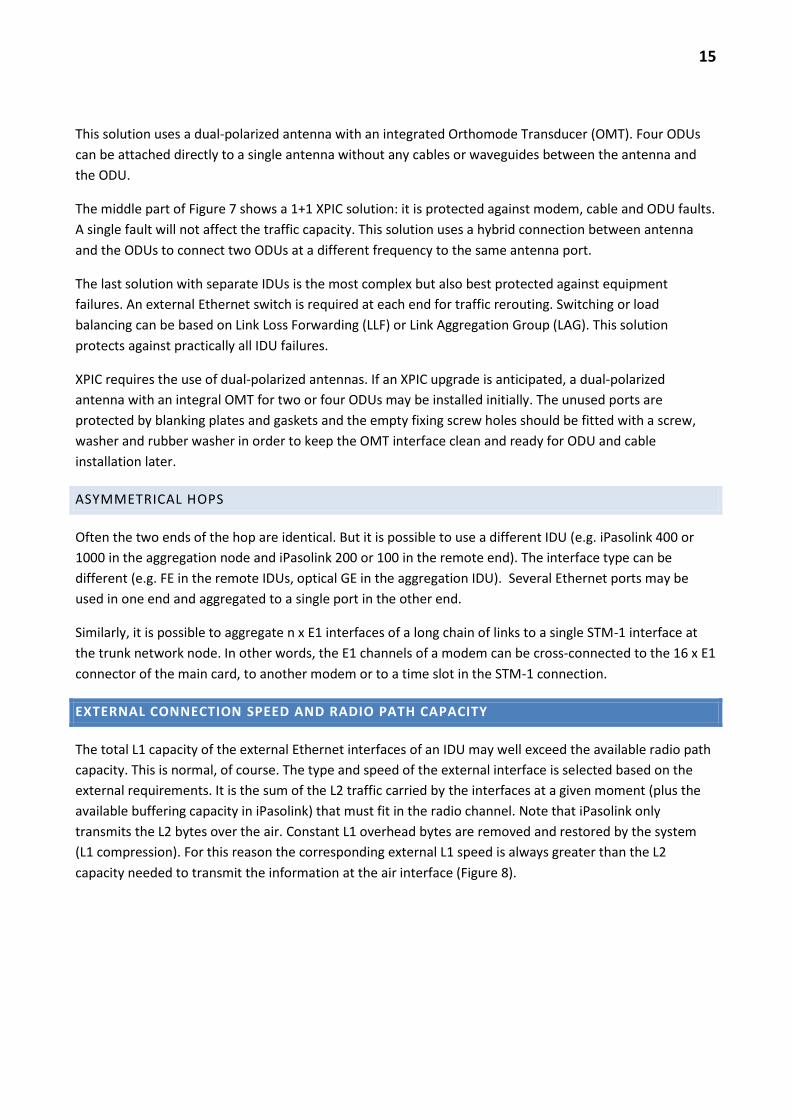
This solution uses a dual-polarized antenna with an integrated Orthomode Transducer (OMT). Four ODUs
can be attached directly to a single antenna without any cables or waveguides between the antenna and
the ODU.
The middle part of Figure 7 shows a 1+1 XPIC solution: it is protected against modem, cable and ODU faults.
A single fault will not affect the traffic capacity. This solution uses a hybrid connection between antenna
and the ODUs to connect two ODUs at a different frequency to the same antenna port.
The last solution with separate IDUs is the most complex but also best protected against equipment
failures. An external Ethernet switch is required at each end for traffic rerouting. Switching or load
balancing can be based on Link Loss Forwarding (LLF) or Link Aggregation Group (LAG). This solution
protects against practically all IDU failures.
XPIC requires the use of dual-polarized antennas. If an XPIC upgrade is anticipated, a dual-polarized
antenna with an integral OMT for two or four ODUs may be installed initially. The unused ports are
protected by blanking plates and gaskets and the empty fixing screw holes should be fitted with a screw,
washer and rubber washer in order to keep the OMT interface clean and ready for ODU and cable
installation later.
ASYMMETRICAL HOPS
Often the two ends of the hop are identical. But it is possible to use a different IDU (e.g. iPasolink 400 or
1000 in the aggregation node and iPasolink 200 or 100 in the remote end). The interface type can be
different (e.g. FE in the remote IDUs, optical GE in the aggregation IDU). Several Ethernet ports may be
used in one end and aggregated to a single port in the other end.
Similarly, it is possible to aggregate n x E1 interfaces of a long chain of links to a single STM-1 interface at
the trunk network node. In other words, the E1 channels of a modem can be cross-connected to the 16 x E1
connector of the main card, to another modem or to a time slot in the STM-1 connection.
EXTERNAL CONNECTION SPEED AND RADIO PATH CAPACITY
The total L1 capacity of the external Ethernet interfaces of an IDU may well exceed the available radio path
capacity. This is normal, of course. The type and speed of the external interface is selected based on the
external requirements. It is the sum of the L2 traffic carried by the interfaces at a given moment (plus the
available buffering capacity in iPasolink) that must fit in the radio channel. Note that iPasolink only
transmits the L2 bytes over the air. Constant L1 overhead bytes are removed and restored by the system
(L1 compression). For this reason the corresponding external L1 speed is always greater than the L2
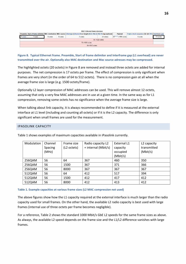
capacity needed to transmit the information at the air interface (Figure 8).
16
Figure 8. Typical Ethernet frame. Preamble, Start of frame delimiter and Interframe gap (L1 overhead) are never
transmitted over the air. Optionally also MAC destination and Mac source adresses may be compressed.
The highlighted octets (20 octets) in Figure 8 are removed and instead three octets are added for internal
purposes. The net compression is 17 octets per frame. The effect of compression is only significant when
frames are very short (in the order of 64 to 512 octets). There is no compression gain at all when the
average frame size is large (e.g. 1500 octets/frame).
Optionally L2 layer compression of MAC addresses can be used. This will remove almost 12 octets,
assuming that only a very few MAC addresses are in use at a given time. In the same way as for L1
compression, removing some octets has no significance when the average frame size is large.
When talking about link capacity, it is always recommended to define if it is measured at the external
interface at L1 level (including and counting all octets) or if it is the L2 capacity. The difference is only
significant when small frames are used for the measurement.
IPASOLINK CAPACITY
Table 1 shows examples of maximum capacities available in iPasolink currently.
Modulation Channel Spacing (MHz)
Frame size (L2 octets)
Radio capacity L2 + internal (Mbit/s)
External L1 capacity occupied (Mbit/s)
L2 capacity transmitted (Mbit/s)
256QAM 56 64 367 460 350
256QAM 56 1500 367 371 366
256QAM 56 8000 367 367 367
512QAM 56 64 412 517 394
512QAM 56 1500 412 417 412
512QAM 56 8000 412 413 412
Table 1. Example capacities at various frame sizes (L2 MAC compression not used)
The above figures show how the L1 capacity required at the external interface is much larger than the radio
capacity used for small frames. On the other hand, the available L2 radio capacity is best used with large
frames (internal use of three octets per frame becomes negligible).
For a reference, Table 2 shows the standard 1000 Mbit/s GbE L2 speeds for the same frame sizes as above.
As always, the available L2 speed depends on the frame size and the L1/L2 difference vanishes with large
frames.

17
Frame size (L2 octets)
L1 capacity (Mbit/s)
L2 capacity (Mbit/s)
64 1000 761,9
1500 1000 986,8
8000 1000 997,5
Table 2. GbE interface L2 capacity also depends on the frame size.
If the average frame size were only 64 octets, there would be a problem fitting the 2+0 maximum capacity
at 56 MHz and 512QAM into a single GbE interface. This is because the total L2 speed is 2 x 394 = 788M,
which would need over 1 Gbit/s at interface L1 speed (2 x 517 = 1034M). In other words two modems
could send more packets than a single GbE interface can handle.
In practise the average packet size is always much larger than 64 octets, perhaps 500-1000 octets, and then
the GbE interface can handle all the packets delivered by two modems.
The compression can become an interpretation problem when measuring the link capacity with the
smallest frame size. If the capacity is defined using the smallest frames only, that capacity cannot be
achieved with real traffic and a larger average frame size. This may cause SLA problems between the
operator and the end customer. It is recommended that the capacity is defined and measured using the
largest possible frames which will remove the L1/L2 difference. Then the real capacity achievable is always
slightly larger than the measured one.
Table 3 shows iPasolink radio capacities with each available modulation and channel spacing. This value is
practically identical with the L1 and L2 capacity when the average frame size is 1500 octets or larger.
(1024QAM and 2048QAM are preliminary values).
Radio capacity (Mbit/s)
Modulation
Channel spacing
7MHz 14MHz 28MHz 56MHz
QPSK 10 22 45 91
16QAM 22 45 91 183
32QAM 27 56 113 228
64QAM 33 67 136 274
128QAM 39 79 159 320
256QAM 45 90 182 366
512QAM - - 205 412
(1024QAM) - - (228) (458)
(2048QAM) - - (251) (504)
Table 3. iPasolink radio capacity.

18
QOS AND OVERPROVISIONING
If the traffic coming to the IDU is very bursty and time-variable, so called “overprovisioning” (or
“overbooking”) of the radio is a possible method for cost savings. Due to the statistical variation and the
fact that the traffic peaks seldom occur simultaneously. The combined traffic has a peak value less than the
sum of the peak values of contributing interfaces.
The random nature of real traffic will sometimes cause the radio channel to be overloaded. This will happen
more often when unfavourable weather conditions force the use of lower modulation formats (when
adaptive modulation, AMR, is used). Overprovisioning must take into account overloading conditions and
the priority of frames must be considered. Obviously less important traffic and non-realtime traffic should
be dropped first.
iPasolink can use statistical multiplexing very effectively because it understands the incoming frame
priority, it may shape the traffic and there is a queuing mechanism to the radio path.
The operator should design the radio capacity based on the traffic statistics and SLA requirements and
define the QoS parameters required in the radio.
ADAPTIVE MODULATION
As was the case already with the previous generation PASOLINK NEO HP AMR, iPasolink may use adaptive
modulation (AMR) which improves the reliability of high priority traffic or alternatively increases the
available capacity for lower priority traffic during majority of time. AMR is especially important when using
high modulation formats with lower sensitivity and lower fade margin resulting in higher equipment costs
such as larger antenna. With AMR different traffic classes may have a different fade margin and availability.
Figure 9. Adaptive modulation.
An example: the most cost-efficient solution could be that a nominally 366 Mbit/s hop is designed for
99,9993% availability for 16QAM 183 Mbit/s for “Business Critical and Real Time” traffic. For Best Effort
traffic, the full 366 Mbit/s 256QAM availability could be 99,993% of time. In this manner, the last 25% of
traffic (e.g. Real Time) would have practically 100% availability (91 Mbit/s QPSK). This kind of availability

19
design is of course based on the empirical rain and multipath fading models for the average worst month.
No real guarantee for the availability due to weather conditions can be given, but statistically the designed
hops will meet the targets.
A more expensive solution would be to design the hop for 99,999% availability for the full 256QAM 366
Mbit/s. This would mean using larger antennas and/or shorter hop lengths (i.e. additional CAPEX). The
adaptive modulation would then ensure that high priority traffic at lower capacity would have much better
availability.
It is crucial that the hop attenuation after aligning the antenna is correct when compared to the fade
margin calculation. If the designed fade margin is not available, the availability for the various traffic
classes cannot be achieved.

20
MAIN SPECIFICATIONS
The following tables present the main technical specifications of the iPasolink 400 equipment. Some
performance data are given in Appendix A.
PDH SDH LAN
ODU frequency bands 6, 7, 8, 10, 11, 13, 15, 18, 23, 26, 28, 32, 38, 42 GHz
Capacity per modem (*512QAM Modem HW 2.00 and later)
152 x E1 (256QAM) 1x155 Mbit/s tai 2x155 Mbit/s
< 412 Mbit/s*
External line signals and interfaces
E1 (ITU-T G.703) 75/120 ohms MDR-68 female (16xE1) (See Appendix B and C).
S-1.1/L-1.1 (ITU-T G.957): LC ITU-T G.703: DIN 1.0/2.3
10/100/1000 Base-T(X):RJ-45 1000 Base-SX/LX: LC
IDU-ODU connectors, cable attenuation allowed
ODU: N-female 50 ohms IDU: TNC-female 50 ohms Maximum attenuation: 25 dB at 340 MHz (E.g. Draka RFA ½” > 500m)
ODU RX level monitor connector F-female (DC voltage proportional to the input level at antenna port)
Channel spacing and radio capacity
QPSK 7/14/28/56 MHz 11/22/45/91 Mbit/s
16QAM 7/14/28/56 MHz 22/45/91/183 Mbit/s
32QAM 7/14/28/56 MHz 28/56/114/229 Mbit/s
128QAM 7/14/28/56 MHz 39/79/160/320 Mbit/s
256QAM 7/14/28/56 MHz 45/90/183/366 Mbit/s
512QAM -/-/28/56 MHz -/-/205/412 Mbit/s
Environmental conditions (ODU for outdoor use, IDU for temperature-controlled indoor use or outdoor cabinet with similar conditions)
Full specifications: ODU: -33…+50 ˚C, IDU: -5…+50 ˚C Operation guaranteed: ODU: -40…+55 ˚C, IDU: -10…+55 ˚C Transportation: ODU, IDU: -40…+70 ˚C Relative humidity: ODU: 100 % IDU: 90 % (no condensing allowed)
Power supply -48 VDC (-40,5… -57 VDC), Fuse/over current protection > 10A (6A for max 3 x ODU)
Power consumption (1+0) ODU: 30 W (6-11 GHz), 23 W (13-52 GHz) IDU: 45 W + 10W/modem + 8W/GbE-card Total < 210 W (fully equipped, feeding four 6 GHz ODUs)
Mechanical data ODU: 237(l)x237(w)x101(h); ~3-3,5 kg IDU: 19” 1U (483x44x240mm); ~3-4 kg (including plug-in units)
LCT (local element management)
LCT port: RJ45 10/100Base-T using a web browser
Management port NMS/NE ports: RJ-45 10/100 Base-T
Service Channels (SC) RS-232C 9600 bit/s 2 ch., V.11 64/192 kbit/s 2ch; D-44 female (See App. F)
External relay output/input (AUX/ALM)
D-44 female (See Appendix F)
Others USB-port for a memory stick (USB v.2.0)
Table 4. NEC iPasolink 400 main technical data

21
Switching capacity 48 Gbit/s (theoretical, exceeds the maximum interface capacity available per IDU)
MAC-table Address table per each VLAN 128k (configurable)
VLAN
802.1Q port and tag, tunnel 802.1ad port and tag, selective 4094 VLAN ID per IDU MEF9 certified EPL, EVPL and ELAN; L2CP
tunnelling (multicast frame filtering/forwarding configurable)
Jumbo frames max. 2000/9600 octets (FE/GE)
QoS
Ingress ports Configurable mapping QoS -> internal
priority: based on VLAN CoS/IPv4 DSCP/IPv6 DSCP/MPLS Exp
Configurable mapping internal priority -> 4/8 egress queues (port based setting: default one to one and two user profiles plus one user-defined DSCP profile i.e. four profiles total per IDU)
MEF/RFC4115 based ”policing” (CIR/EIR/CBS/EBS) per QoS-class and optionally per VLAN
For each egress port Queuing 4 or 8 classes 4xSP, 4xDWRR,
SP+3xDWRR, 8xSP, SP+7xDWRR, 2xSP+6xDWRR,
Shaping per class Buffer size setting per class Yellow/Green threshold per class Egress port shaping
ETH OAM 802.1ag Service OAM (CC/LB/LT) Y.1731 PM (LM/DM)
Equipment/traffic protection STP/RSTP, G.8032v2 ERPS (Ethernet Ring)
Traffic aggregation over the air 802.1AX, 1:1 LACP redundancy; RTA load balancing based on L2 (MAC, VID, TPID, port) or L3 (IP source and destination, both TCP/UDP port numbers), frame ordering preserved; maximum speed per stream is equal to single modem speed; Physical RTA: maximum speed per stream equal to combined capacity minus a small overhead
Synchronous Ethernet Supported (optional clock module required)
TDM PWE RFC4533 SAToP (MEF8)
Other Link Loss Forwarding, Mirror/Monitor, Broadcast Storm Control, L2 Filter, Port Isolation
Table 5. iPasolink 400 Ethernet-switch main characteristics

22
IDU CONFIGURATIONS
Table 6 lists the available plug-in unit options.
Type number Name Description
NWA-055298-001 MC-A4 Control unit with 16E1(MDR) + 2GbE(RJ45)+ 2GbE(SFP) – mandatory
NWA-055300-xxx*) MODEM-A
Modem can be installed in universal slots 1 to 4, optional. TNC connector (female) for the ODU-cable. Grounding connector. Modem power switch. XPIC-connectors. 512QAM supported HW-version 2.00 and later
NWA-055303-001 NWA-055303-101
GbE-A 2GbE(T) + 2GbE(SFP) interface card for slots 1 to 4, optional
NWA-060926-002-01 Sumitomo SCP6G44-GL-CWH
LX SFP
LX SFP Module 1000 Mbit/s
NWA-060926-003-01 Finisar FCLF8521P2BTL
GbE T (TRI) SFP Electrical GbE (TRI-MODE) SFP: 10/100/1000 BASE-T
NWA-055294-001,-002 FAN-C Fan unit, mandatory
NWA-055310-001 PS-A4 Power supply unit (one mandatory, second optional)
CBE-009983-001,-003 136147-3 SFP-port protecting plug
NWM-034915-001 BLANK COVER Universal Slot blank cover (mandatory when Universal Slot empty)
NWM-034910-001 BLANK COVER Power Supply blank cover (mandatory when PS not installed in slot)
NEC-XCB-1023-0,4 XPIC CABLE XPIC cable 40 cm, two cables per XPIC modem pair
NWA-055302-001 NWA-055302-101
16E1-A 16 x E1 interface card for universal slots 1 to 4, optional
NWA-055304-004 NWA-055304-104
STM1-A STM-1 interface card for universal slots 1 to 4 Optical Interface(S-1.1)/(L-1.1) or Electrical G.703, optional
NWA-055306-001 MSE-A PWE-card for universal slots 1 to 4, optional. For transporting E1 over Ethernet packets.
NWA-055307-001 AUX-A Additional interfaces (ALM, EOW, NE2) , for universal slots 1 to 4, optional.
NWA-055289-002 CLK2M-C
Clock module, installed on the MC-A4 card, required for Synchronous Ethernet and SDH-demultiplexing. Optional. Can be retrofitted in the field.
Table 6. IDU cards
*) xxx = 001 (discontinued); 202 = ASIC version; 102 = PRTA version (required for L1 physical Radio Traffic Aggregation); 322 =
unified version, available 9/2012.
Limitation: the SFP modules installed in each MC-A4, GbE-A or STM1-A SFP port have to be identical or
the right port empty. Third party SFP modules do not generate an alarm (note: FW version dependent)
but correct operation is guaranteed only for an SFP delivered by NEC.

23
Figure 10 presents the plug-in unit configurations in the indoor unit and Figure 11 depicts the plug-in units.
Figure 10. Indoor unit NWA-055268-001 and its ODU connection
Figure 11. Universal Slot-modules/cards. Note: Modem-A module: the old HW-version has no ONLINE led.
24
PDH-INTERFACES
The control unit (main card) MC-A4 and 16E1-A-card MDR68-connector and pin layout is identical with the
Pasolink NEO HP AMR MDR68-connector. See Appendix B and the section on ”PDH provisioning”.
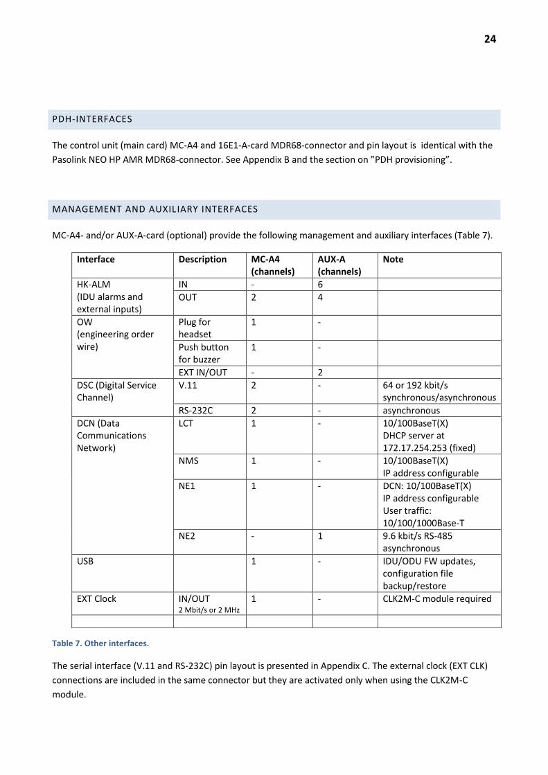
MANAGEMENT AND AUXILIARY INTERFACES
MC-A4- and/or AUX-A-card (optional) provide the following management and auxiliary interfaces (Table 7).
Interface Description MC-A4 (channels)
AUX-A (channels)
Note
HK-ALM (IDU alarms and external inputs)
IN - 6
OUT 2 4
OW (engineering order wire)
Plug for headset
1 -
Push button for buzzer
1 -
EXT IN/OUT - 2
DSC (Digital Service Channel)
V.11 2 - 64 or 192 kbit/s synchronous/asynchronous
RS-232C 2 - asynchronous
DCN (Data Communications Network)
LCT 1 - 10/100BaseT(X) DHCP server at 172.17.254.253 (fixed)
NMS 1 - 10/100BaseT(X) IP address configurable
NE1 1 - DCN: 10/100BaseT(X) IP address configurable User traffic: 10/100/1000Base-T
NE2
- 1 9.6 kbit/s RS-485 asynchronous
USB 1 - IDU/ODU FW updates, configuration file backup/restore
EXT Clock IN/OUT 2 Mbit/s or 2 MHz
1 - CLK2M-C module required
Table 7. Other interfaces.
The serial interface (V.11 and RS-232C) pin layout is presented in Appendix C. The external clock (EXT CLK)
connections are included in the same connector but they are activated only when using the CLK2M-C
module.

25
INDOOR UNIT CONFIGURATIONS
Figure 12. Modem positions for various single and dual IDU setups
Figure 12 presents a summary on possible modem positions when using a single or dual IDU setup. For
additional detais, see the Ordering Guide.

26
ORDERING CODES
See the Price List and the Ordering Guide for the ordering codes.
PREINSTALLED LICENSES
When agreed between the customer and NEC, the IDU may have all the licenses preinstalled. Certain
functionalities are then always paid for and available for immediate use. Certain functions require
additional payment before use. See the Price List and the Ordering Guide for details.
In case of a missing license key, it has to be prepared and delivered by the factory for installation. The
following serial numbers are required and are associated with the license key:
- iPasolink 200: IDU serial number
- iPasolink 400: MC-A4 card serial number
- iPasolink 1000: serial number of TERM-M card
SAFETY ISSUES
The following presents some basic safety issues related to microwave installations.
OPEN WAVEGUIDE AND OPTICAL CONNECTORS
During the installation and operation it is important to remember at all times that any open microwave
connection (waveguide or coaxial) will radiate microwave signals. Similarly, open optical connectors may
emit invisible optical signals. These signals may damage the eye permanently if the connector is too close
to the eye. The risk is a microwave-induced cataract or laser burn damage of the retina. The damage is
similar to any burn damage and is caused by excessive heating of the tissue and occurs almost
instantaneously.
AVOID THE FRONT OF THE ANTENNA
One should avoid the intense radiation close to any radiating aperture unless the system has been designed
for close human exposure. The appropriate national safety regulations have to be followed. Microwave
antennas may cause radiation fields exceeding the regulated limits. Working in front of an antenna should
be avoided when the transmitter is switched on.

27
RADIATION MONITORING DEVICES
It is recommended that the installation crews use personal radiation monitoring devices. They are most
useful when working close to high power HF/VHF/UHF transmitting antennas, in order to ensure that
power has been switched off or reduced to a safe level.
There are no cumulative long-term radiation effects known for non-ionizing radiation such as microwaves.
The damage is caused only when the tissue temperature increases too much. Low level non-ionizing
radiation below the excessive heating level is not known to cause any long-term effects. In this respect
microwave radiation differs from X-ray, alpha, beta and gamma radiation, where no safe limit exists and it
is the total cumulative dosage that matters.
For monitoring microwave radiation the monitoring devices are not as useful as in case of HF/VHF/UHF
radiation. The radiation is very local. When the upper body is in front of a microwave antenna, the
monitoring device hanging on the belt may not see any significant levels even if the legal safe limit is locally
exceeded.
SAFETY DISTANCE FOR THE PUBLIC EXPOSURE
The antenna must not be installed in such a place where it causes too high exposure to the public. The safe
distance depends on the transmitter power, antenna size and frequency band. In case of iPasolink the safe
distance is presented in Table 12. The calculation assumes maximum two (2) IHG ODUs per antenna and
the assumed legal limit is 10 W/m2. The calculation is based on the “far field formula”, which is always on
the safe side.
Antenna diameter (m)
F (GHz) 0,3 0,6 1,2 1,8 2,4 3
6 3,6 7,2 10,8 14,4 18,0
7 4,2 8,4 12,6 16,8 21,0
13 2,5 4,9 9,9 14,8
18 3,0 6,1 12,2
23 3,9 7,8 15,5
Table 12. Safety distance in front of the antenna (metres). Two IHG ODU per antenna.
The radiation is concentrated in front of the antenna aperture and the zone to avoid is a cylinder with the
length indicated and diameter equal to antenna diameter. E.g. for a 7 GHz 3m antenna the safety zone is a
cylinder 3m by 21m in front of the antenna. In practice some extra margin should be given, especially when
it is easily available.
In reality the far field formula overestimates the power density near the antenna. Therefore the distances
are in most cases pessimistic, especially in case of large diameter antennas it may well be that the 10 W/m2
limit is not exceeded at any distance from the antenna.

28
One should be aware that the worst hot spot is usually 1 to 3 antenna diameter from the antenna aperture
on the antenna symmetry axis. Another rule of thumb is that the maximum intensity is larger for a smaller
antenna. The most dangerous “antenna” is an open waveguide (i.e. very small radiating aperture). The
safety zone for a large antenna can be very long but the maximum intensity much lower than in case of a
small antenna.
INDOOR UNIT INSTALLATION
The indoor unit is installed in a 19-inch or ETSI rack. The delivery includes brackets for both racks. There is
an AMP-power connector included in the box but it is recommended to use a factory-made power cable.
The indoor unit is cabled as usual (grounding, power cable, Ethernet, E1, SDH, management). It is not
necessary to connect all E1 channels to the external connector and cross-connection frame: internal cross-
connection can be used for E1 signals between modems. Same applies for Ethernet.
VENTILATION
iPasolink does not necessarily require any free space above and below the IDU due to cooling, but there has
to be enough free space on each side of the IDU inside the rack, because the air intake and fan exhaust is
on the side.
Free space may be required when there is some other equipment requiring free space for cooling. Also
cabling is easier when there is free space between units. Labelling of the modems is easier on the top side
of the IDU. Therefore it is recommended to leave 1U of free space above and below each IDU.
ENVIRONMENTAL REQUIREMENTS
According to the specifications, the indoor unit operates within -5 to +50 degrees Celsius and the maximum
non-condensing relative humidity is 90 per cent.
The limits indicate the allowed short-term temperatures, e.g. during cooling system failure. Long-term
average temperatures should be kept as low as possible, however, because a high average temperature will
decrease the MTBF of any electronic equipment. The number of failures will typically double when the
average temperature increases by 10 degrees.
The indoor units should not be installed close to the ceiling: the distance should be at least one
metre.
Hot air currents should be avoided (eg. the exhaust of a base station cabinet fan).
The cable entry points have to be sealed properly to prevent rain water entering the shelter.
29
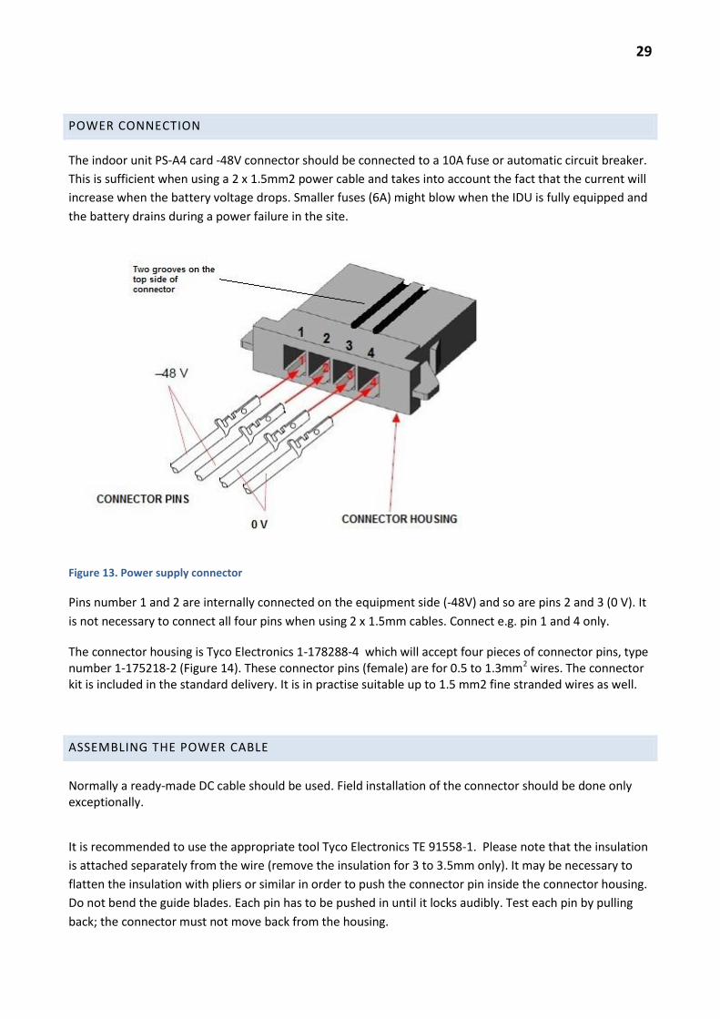
POWER CONNECTION
The indoor unit PS-A4 card -48V connector should be connected to a 10A fuse or automatic circuit breaker.
This is sufficient when using a 2 x 1.5mm2 power cable and takes into account the fact that the current will
increase when the battery voltage drops. Smaller fuses (6A) might blow when the IDU is fully equipped and
the battery drains during a power failure in the site.
Figure 13. Power supply connector
Pins number 1 and 2 are internally connected on the equipment side (-48V) and so are pins 2 and 3 (0 V). It
is not necessary to connect all four pins when using 2 x 1.5mm cables. Connect e.g. pin 1 and 4 only.
The connector housing is Tyco Electronics 1-178288-4 which will accept four pieces of connector pins, type number 1-175218-2 (Figure 14). These connector pins (female) are for 0.5 to 1.3mm2 wires. The connector kit is included in the standard delivery. It is in practise suitable up to 1.5 mm2 fine stranded wires as well.
ASSEMBLING THE POWER CABLE
Normally a ready-made DC cable should be used. Field installation of the connector should be done only exceptionally.
It is recommended to use the appropriate tool Tyco Electronics TE 91558-1. Please note that the insulation
is attached separately from the wire (remove the insulation for 3 to 3.5mm only). It may be necessary to
flatten the insulation with pliers or similar in order to push the connector pin inside the connector housing.
Do not bend the guide blades. Each pin has to be pushed in until it locks audibly. Test each pin by pulling
back; the connector must not move back from the housing.

30
Figure 14. Connector pin. The two guide blades (at the centre of the pin pointing upwards) should not be bent.
Crimp the insulation blades and the conductor barrel only.
ETHERNET CABLE CONNECTIONS
The Ethernet cabling is done in the usual manner: electrical using Cat6 cables and optical using LX-type
cables with LC-connectors. Alternatively SX-type SFPs are available.
When inserting the SFP modules make sure that the module is locked in place (keep the latch in the locked
or up position). Remove by pressing the latch fully down until the module is released. Never try to pull the
SFP out when the latch is not pressed fully down.
All optical connectors should be cleaned using a cleaning tool. Empty connectors have to be protected with
plugs.
PDH CONNECTIONS
There are several types of ready-made E1 cables available (8 channels and 16 channels), one end with
MDR68, the other end without any connector or with a connector suitable for a I/O-board. Please consult
the price list.
ODU INSTALLATION
iPasolink uses frequency division duplex and therefore ODU is always either a LOW or HIGH version working
on the same sub band. The LOW version has the transmit frequency lower than the receive frequency and
HIGH version is of course the opposite. Each hop has to have one HIGH and one LOW type ODU of the same
sub band. Moreover, the correct site has to use HIGH as instructed by the frequency planner (given in the

31
license). Note that all ODUs on the same site have to be either HIGH or LOW, if they use the same
frequency band.
The ODU version is indicated as HIGH or LOW on the box and on the ODU label.
Andrew antennas are installed on a steel tube with outer diameter 48 to 115 mm (0.3m and 0.6m),
65 to 115mm (0.8m) or 115 mm (1.2m and larger).
Aerial Oy antennas use 100mm installation tubes.
The ODU mounting brackets for separate installation are designed for a tube of 48 to 115 mm outer
diameter.
6 GHZ ODU WITH STANDARD WAVEGUIDE
6 GHZ ODU may use either N-type coaxial or PDR70 type waveguide interface. It should be installed
separately.
An installation bracket without any adapter is required for the ODU. Either a coaxial cable or flexible wave
guide is installed between the ODU and a separately installed antenna. In case of the waveguide ODU
version with PDR70 the flexible and twistable waveguide should have a UDR70 flange at the ODU end. The
gasket (O-ring) has to be installed for weather-proofing. The waveguide should be attached at the middle in
order to avoid vibration damage caused by wind. The attachment method must not change the shape of
the waveguide, the bending radius has to be sufficient and twisting should be minimized.
Note. If a “pressurized” e.g. a PDR-flange must interface another identical flange, then a double thickness
gasket (O-ring) is required or at least two normal-size gaskets are needed. Usually PDR will interface to UDR
with a normal gasket.
Figure 15. ODU 6 GHz with standard IEC waveguide flange. Mounting bracket without adapter.

32
In case of N-type coaxial ODU, the interconnecting cable would be N-type and the antenna would need to
have either an N-type connector or to be equipped with a N to PDR70 adapter.
SEPARATE INSTALLATION OF 7 AND 13 GHZ DIRECT MOUNT ODU
The “antenna direct mount” type ODUs for 7 GHz and 13 GHz are possible to install directly to the antenna
using the NEC proprietary antenna interface. It is also possible to use a separate installation using a
waveguide. The ODU installation bracket will then have an adapter from NEC interface to the appropriate
IEC standard waveguide interface.
7 GHz uses UDR/PDR84 flanges and 13 GHz uses PBR/UBR140. See Figure 16 for the 7 GHz case. Again,
UDR to PDR or PBR to UBR joints should be used with the suitable gasket or O-ring for weather-proofing.
Figure 16. 7 GHz separate mount using a direct mount ODU and mounting bracket with adapter
DIRECT MOUNT INSTALLATION
In the 7 GHz bands and higher, the standard installation method is to use e.g. Andrew antennas with an
integrated NEC proprietary antenna interface, which includes the four attaching holes and the hole for the
guide pin etc. See Figure 17. The antenna is fixed to the installation tube and the direct mount type ODU to
the antenna.
33
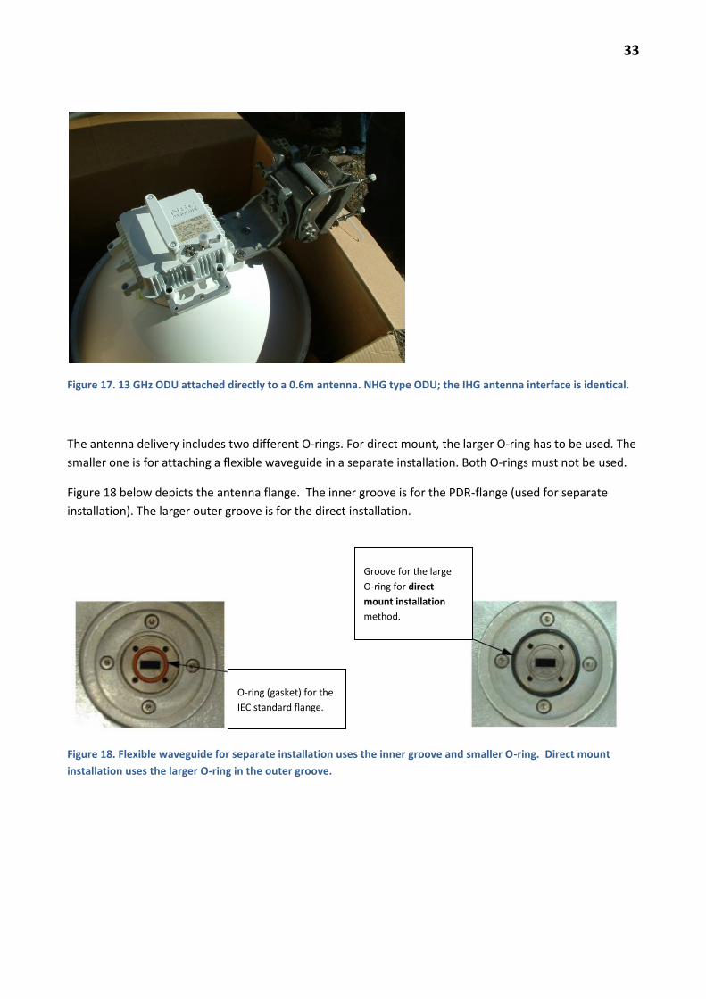
Figure 17. 13 GHz ODU attached directly to a 0.6m antenna. NHG type ODU; the IHG antenna interface is identical.
The antenna delivery includes two different O-rings. For direct mount, the larger O-ring has to be used. The
smaller one is for attaching a flexible waveguide in a separate installation. Both O-rings must not be used.
Figure 18 below depicts the antenna flange. The inner groove is for the PDR-flange (used for separate
installation). The larger outer groove is for the direct installation.
Figure 18. Flexible waveguide for separate installation uses the inner groove and smaller O-ring. Direct mount
installation uses the larger O-ring in the outer groove.
Groove for the large
O-ring for direct
mount installation
method.
O-ring (gasket) for the
IEC standard flange.
34
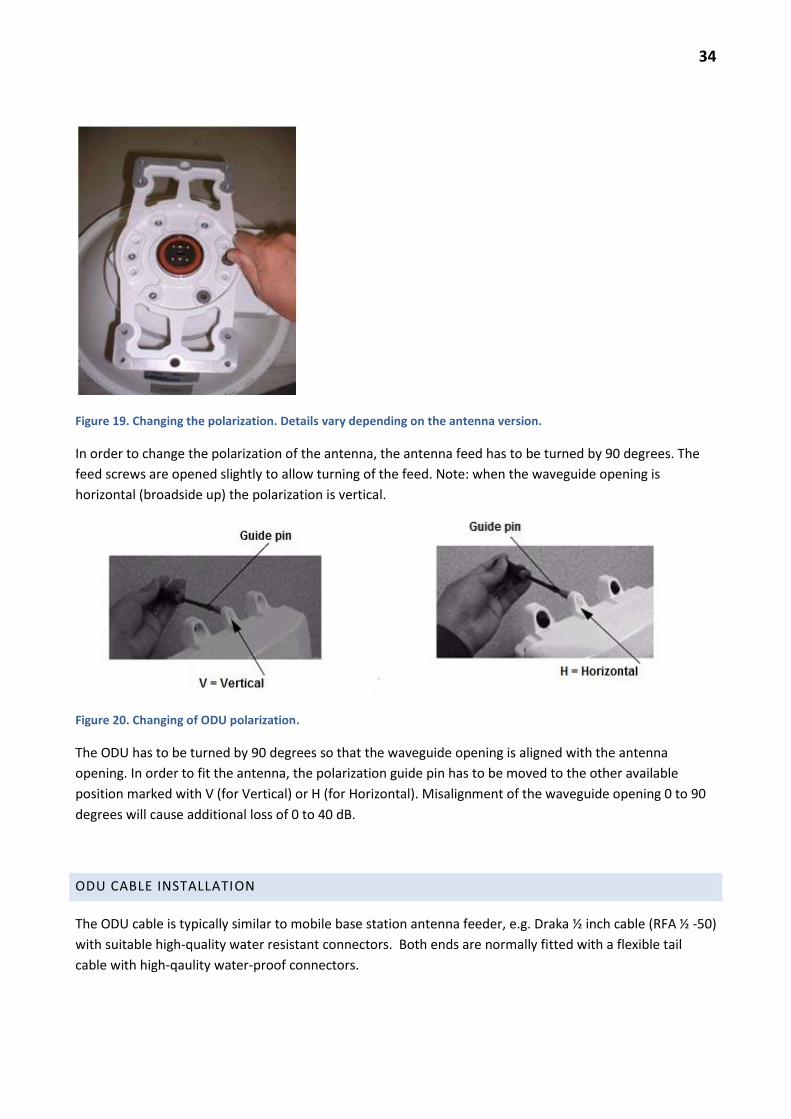
Figure 19. Changing the polarization. Details vary depending on the antenna version.
In order to change the polarization of the antenna, the antenna feed has to be turned by 90 degrees. The
feed screws are opened slightly to allow turning of the feed. Note: when the waveguide opening is
horizontal (broadside up) the polarization is vertical.
Figure 20. Changing of ODU polarization.
The ODU has to be turned by 90 degrees so that the waveguide opening is aligned with the antenna
opening. In order to fit the antenna, the polarization guide pin has to be moved to the other available
position marked with V (for Vertical) or H (for Horizontal). Misalignment of the waveguide opening 0 to 90
degrees will cause additional loss of 0 to 40 dB.
ODU CABLE INSTALLATION
The ODU cable is typically similar to mobile base station antenna feeder, e.g. Draka ½ inch cable (RFA ½ -50)
with suitable high-quality water resistant connectors. Both ends are normally fitted with a flexible tail
cable with high-qaulity water-proof connectors.
35
The maximum cable length when using the above Draka cable as an example is about 500m, which includes
an allowance for the higher per unit attenuation in the tail cables.
Cables should be marked as required by the tower/shelter owner. Cables should be attached using proper
permanent cable brackets – not temporary plastic cable ties. The minimum bending radius should be
observed (e.g. RFA ½ - 50: 70mm). The cable outer conductor must not be deformed by the cable brackets.
One well-known installation fault is a periodic deformation of the cable causing multiple reflections, signal
distortion and bit errors.
CABLE CONNECTORS
Cable connectors have to be installed to the cable following the manufacturer’s instruction strictly and
using the appropriate tools. The connector has to be sealed as recommended to the cable jacket using self
vulcanizing rubber tape or a heat shrink tube with melting glue.
Connectors which are installed improperly may be destroyed by moisture and electrochemical corrosion
within a few months. The connector has to be absolutely dry when installed to the cable and also when the
actual connection between the two connectors is made.
The connector type has to be chosen so that the connection is water-proof without using any external seal
(rubber tape) covering the two connectors. Taped connections are difficult to check for tightness of the
connection between connectors. Rubber taping of the connection is thus not recommended.
GROUNDING
OPERATOR’S OR SHELTER/TOWER OWNER’S GROUNDING INSTRUCTIONS AND LOCAL
REGULATIONS ARE TO BE FOLLOWED.
GROUNDING OUTSIDE
The ODU should be grounded to the tower grounding wire using 16 mm2 or larger copper cable. The size of
the grounding terminal screw is M4 (Metric 4 mm). A suitable cable lug (e.g. 16-5.5, tinned copper) should
be used. The connection to the tower grounding wire should be done using an appropriate C-type
connector (Cu-Cu or Cu-Fe).
In case of a roof-top installation, the grounding should use a 16 mm2 or larger copper cable from the ODU
ground terminal
directly to the main ground bar of the building
to the nearest ground wire of the lightning protection system of the building
to a TV common antenna system ground wire provided that it is minimum 6 mm2 Cu and continuity
to the main grounding bar of the building is verified by measurement,
directly to the main grounding bar of the equipment room where the IDU is installed.
36
Grounding wires should be installed as straightforward as possible, avoiding bends and loops
GROUNDING IN THE SHELTER
Grounding of the lower end of the ODU cable should be done at the connection between the ½-inch cable
and the tail cable as close as possible to the wall feed-through point to the nearest grounding bar or wire
using as short 16 mm2 Cu cable as possible. The length of the tail cable should be suitable so that the
grounding point is close to the outer wall.
The indoor unit should be grounded using the grounding connector of the modem to the grounding bar of
the rack. Note that grounding using the rack screws is not reliable as the rack maybe painted using non-
conducting paint. The rack grounding bar should be connected to the shelter grounding bus. All grounding
wires should be as short as possible without any unnecessary bends or loops. If the grounding wire is too
long, it has to be cut to suitable length. Coiling the extra length of wire is equivalent to leaving the
grounding wire disconnected due to the inductance seen by lightning currents.
SUITABLE GROUNDING CONNECTORS
Tyco Electronics connecotr types:
C-LOK 1-83016-0 Cu16-Cu16 C-LOK 0-81713-3 Cu16-Cu50 or 3/8" grounding rod C-LOK 0-83713-1 Cu16-1/2" grounding rod C-LOK 0-81663-1 Cu16-Fe 7*1.20 tai 7*1.57 steel wire C-LOK 0-81663-6 Cu16-Fe 7*2.12 25mm2 steel guy wire C-LOK 0-81663-5 Cu16-Fe 7*2.44 35mm2 steel guy wire
Ensto C-connector (crimp connector)
SE 36 Cu 16...25mm2 - Cu 16...25mm2
Ensto connector with a tightening nut
SE 12.1 10...70 mm2 - 10...70 mm2
IDU AND CABLE LABELLING
Labelling should follow operator’s instructions.
OVERVOLTAGE PROTECTION
There is no requirement to install any overvoltage protection devices to the IDU/ODU cable. Proper
grounding should ensure that excessive potential differences do not occur.

37
LOCAL MANAGEMENT
MANAGEMENT TOOL
The indoor unit is managed using a PC and a standard web browser.
Note. The previous generation (Pasolink NEO) LCT and PNMTj software are not compatible with iPasolink
nor are there any such versions available.
RECOMMENDED BROWSER
Firefox is the recommended browser, because the ”Menu Bar” of the web page shows the FW-version, the
site name and the modem IP address. Internet Explorer (IE9) does not show these labels, at least not when
using the browser with default settings.
Firefox normally works with the default settings, but it is advisable to set (Tool Bar) Tools -> Options,
”Always ask me where to save files” so that downloaded files can be saved directly to the proper folder.
It may be necessary to change the security settings of the browser to lower level. In case of IE the
”medium-high” level normally works. Firefox should work with the default settings after the standard
installation.
LOCAL CONNECTION
The PC is connected to the LCT port of the IDU using an RJ-45-cable. The LCT port contains a DCHP server
and web server. The PC LAN card should be configured to obtain the IP address automatically.
Figure 23. PC is connected to the LCT port using a LAN cable (RJ-45).
Port name LCT
Port IP address 172.17.254.253
User name Admin
Password 12345678

38
When the DHCP server has given the LAN card an IP address, the default gateway indicated for the LAN
card is the LCT port (and the web page) address. The address is easy to check by running cmd and typing
ipconfig. If necessary, ipconfig -release and ipconfig -renew should get the proper address. Alternatively
disable and enable the LAN card of the PC using the Control Panel (Windows 7).
REMOTE LOGIN USING THE BROWSER
The IDU can be managed remotely in the same way as locally (but with some limitations in allowed
operations). The IDU need not be attached to PNMSj or MS5000. When using the NMS port for logging in,
use the NMS port address if the IDU Bridge1 address is unknown. Then check the local and remote IDU
Bridge1 addresses using the management interface and use the Bridge1 address to log in directly to the
desired IDU.
LOGIN WINDOW
Figure 24. Login window. Default User Name = Admin and Password = 12345678
After logging in the main status page opens in a new window or (recommended) in a new tab, depending
on browser settings.
When the hop is operating properly (and the local and remote Bridge1 addresses are in the same subnet),
the remote IDU can be logged in by using the pull down menu at the top of the main page. If necessary
Refresh (F5) the page. The remote end will open in a new window or tab. Identify each IDU using the Menu
Bar.

39
MAIN PAGE – MENU AND CURRENT STATUS
The page opened shows the Menu tree and the Current Status of the IDU.
Figure 25. Current Status –window shows the active alarms after pressing Refresh.
In order to allow changing of the settings immediately, the status window is not updated until the Refresh is
clicked (FW 3.00.37 and later).
NAMING OF THE IDU AND MODEMS
The IDU and modem ports should be named based on the site name and on the radio hop ID (e.g. opposite
site name, hop ID) following operator’s conventions.
The IDU is named separately from the modem ports. The alarms in the PNMSj are identified by the IDU
name and e.g. Modem Slot1 (= first slot from the left). The IDU name is visible in the web browser Menu
Bas (Firefox, see Fig. 25). The modem port name is visible in the LAN switch (Ethernet) settings.
BASIC SETTINGS
This chapter describes the minimum setting required to align the antennas and establish connection to the
opposite end and establish connection with PNMSj.

40
Note: if suitable basic configuration files are first copied to each IDU, following the Quick Installation Guide
(Appendix D) is sufficient. The basic configuration files should contain all the default settings for the
operator. Then only those settings that vary from each NE to NE need to be changed during installation.
PROVISIONING CLEAR
If the IDU is not at the factory settings, it may be useful to return all Provisioning Settings to factory settings
using Equipment Utility -> Shipment -> Shipment.
This operation disables all modems and other cards and removes all settings under Provisioning. Note: e.g
Network Management Configuration and Security Management settings (such as NMS port adresses and
SNMP, NMS and NTP server addresses etc.) remain unchanged.
Before the Provisioning Clear it is necessary to set the MAINT status on. Select ”Provisioning Clear”. The
IDU will be reset, and it is necessary to wait a few minutes for the reset to complete. The operation is
finished when the MAINT led stops blinking and LCT port is again operable.
Note. Possible only locally using the LCT port. Not possible remotely using the NMS port.
MODULE SETUP
It is normally not useful to use the ”Easy Setup Wizard” because the detailed settings need to be changed
anyway.
Equipment Setup -> Equipment Configuration -> Setup
Changes are made using the Setup button. The setting window shows the Current Setting and on the right
the New Setting is used to input new values. Continue by clicking Next > and OK.

41
Figure 27. Equipment Configuration. Use Setup button to modify.
NE Name – Give IDU name (e.g. Site Name – IDU – IDU#). Maximum 32 characters, no special characters!
Element setting.
Figure 27. NE Name.
42
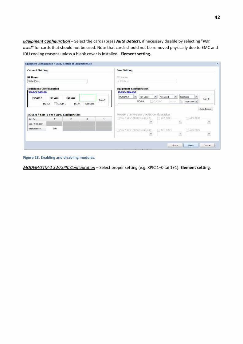
Equipment Configuration – Select the cards (press Auto Detect), if necessary disable by selecting ”Not
used” for cards that should not be used. Note that cards should not be removed physically due to EMC and
IDU cooling reasons unless a blank cover is installed. Element setting.
Figure 28. Enabling and disabling modules.
MODEM/STM-1 SW/XPIC Configuration – Select proper setting (e.g. XPIC 1+0 tai 1+1). Element setting.

43
RADIO CONFIGURATION
Equipment Setup -> Radio Configuration -> Setup
Figure 29. Radio Configuration Setup
The thin green frame in the left upper corner indicates which modem is being set up. Unfortunately the
modem port name is not shown in this window (shown in the Ethernet settings only). ”ODU Information”
shows the available settings of the ODU connected currently. New setting is used to input new values.
Channel Spacing – Input the channel spacing (MHz) given in the frequency license. Element setting.

44
Reference modulation: This selection determines the maximum available power. In order to get maximum
power at QPSK, select Reference Modulation = QPSK. Element setting.
Note. The transmitter power depends on a) MTPC setting and b) current modulation. When the reference
modulation is QPSK, the MTPC setting allows selecting the maximum power. But even with MTPC selected,
the power is automatically adjusted slightly lower according to the current modulation automatically
selected by AMR.
In other words, MTPC includes an automatic TX power fine adjustment part.
EXAMPLE
License allows -6dBW or +24dBm. If the reference modulation is selected as 256QAM and adaptive
modulation is used, the maximum MTPC setting is +19 dBm. When the hop fades, the modulation is
changed all the way down to QPSK, but nevertheless the power is limited to +19 dBm.
If QSPK is selected as the reference, the maximum MTPC setting is +24 dBm. The hop will then tolerate 5 dB
more fading at QPSK (will use +24 dBm), but will normally (no fading) use 256QAM at +19 dBm.
Radio Mode – Select High Capacity, unless otherwise instructed. This setting selects the error correction
code settings. High System Gain will give about 1 dB more fade margin, but will reduce the capacity by
several Mbit/s (shown in ETH Bandwidth). This setting has to be the same at both ends of the hop. Hop
setting.
E1 and STM-1 Mapping (CH) – Capacity reserved for E1- and STM-1 -channels. Change under AMR / Radio
Mapping Configuration. Hop setting.
ETH Bandwidth (Mbps) – Indicates the remaining available Ethernet capacity (Mbit/s) for the reference
modulation. Radio Mode and E1/STM-1 mapping setting will change this value.
TX and RX Frequency (MHz) – Set the frequencies given in the license exactly. Element setting.
If the setting fails, check that the ODU sub band is correct and that the HIGH/LOW version is correct. Check
the ODU information or Inventory. Verify that the correct modem is selected for configuration.
Note. Setting of the frequency is not possible without a proper ODU connected to the modem.
Frame ID – default 1.
Frame ID has to be identical for both modems at each end of the radio connection. Frame ID is checked in
order to prevent communication with a wrong modem in case the remote transmitter fails or fades away.
Using different Frame ID settings may be necessary in a hub with several iPasolink ODUs using the same
channel. XPIC modems using the same channel must have different ID values. Default = 1.
TX Power Control – Select MTPC (fixed power excluding AMR adjustment), unless otherwise instructed.
Default setting = MTPC.
Automatic ATPC mode might be necessary for the remote sites connected to a hub, in order to prevent
excessive interference from other hops re-using the same or adjacent channel.

45
Radio Traffic Aggregation – aggregating the Ethernet capacity of two modems operating on the same hop.
Hop setting.
Figure 30. Radio Configuration changes confirmed by OK.
Settings continue with AMR settings.

46
ADAPTIVE MODULATION RADIO (AMR)
Equipment Setup -> AMR/Radio Mapping Configuration, Setup
Figure 31. Adaptive modulation (AMR) settings. Example: license allows 32QAM, 16QAM and QSPK.
If antennas have not been aligned, select AMR Non Operation. Adaptive modulation changes the
transmit power slightly which would cause problems during the alignment.
After the alignment is ready remember to select AMR Mode (Used) for the appropriate modulations.
Input the number of E1 and STM-1 channels for each modulation level.
Figure 32. Adaptive modulation E1- and STM-1 settings. 8 E1 channels enabled.

47
NETWORK MANAGEMENT (NMS) SETTINGS
Figure 33. Typical NMS subnet
The root element (Root NE) is the indoor unit where this cluster is connected to the NMS DCN using the
NMS port (or in band connection). The rest of the cluster is connected internally or by connecting NMS
ports together at the intermediate sites.
The relevant settings are under
Network Management Setting -> General Setting (Detail)
Note. Network Management Configuration -> General Setting. Ignore this. All settings are under General
Setting (Detail).

48
Figure continues on the next page.

49
Figure 34. NMS settings.
NE2 Port Setting: NE2 is on the AUX-A card, a serial port used when interfacing some legacy equipment.
Default Not Used.
In band Management VLAN Setting - Default “Not Used”. The settings here assume that NMS port is used
for management. Default setting.
Ethernet Port Setting
NMS
Root Element select Used, Auto Negotiation: Enabled and Discovery Usage: Used. LLDP Mode: Standard.
This setting is correct for root elements.
Other elements. Normally NMS port is Not Used unless two IDUs are interconnected. Modify default
setting for normal elements. Element setting.
NMS port can be used for testing the connection to NMS server from the remote sites. The PC should be
given a suitable IP address from the same subnet as the iPasolink cluster by the network administrator.

50
Note that the LCT port can also used for pinging the NMS server using the standard PC settings for local
management, i.e. using the local IP address given by the DHCP server of the LCT port.
NE Branch Setting – If the network elements are in a different subnet than the NMS port or if the NMS port
or NE1 port is used for connecting another subnet then the element is configured as a router. Two or more
Bridges (Bridge1, Bridge2 etc) are configured, these are the ports of the internal router, each having an
address within a different subnet.
Default Gateway. This is the gateway port of the elements’ subnet that is used to access the NMS server. In
the root element where the NMS port is in a different subnet, it is the IP address of the nearest DCN router
where the NMS port is connected. In such a subnet the normal element default gateway is the root
element Bridge1 address (it is the nearest router for those elements). Element setting.
Bridge: if the element uses two or more branches (i.e. the element acts as a router), the NMS port is
Bridge2 and the modem is Bridge1. Note that the PNMSj server is looking for network elements in the
Bridge1 subnet. Element setting.
Bridge No., using the link 01 Bridge 1 i.e. modem IP address is set according to the instructions of the DCN
designer who manages the addresses. Using the link 02 Bridge 2 i.e. the NMS port address is set, etc.
Element setting.
NE1 or NMS or MODEM: the link is used to select the Bridge number assigned to that port. First set up the
IP addresses for the bridges and then select the bridge number for each port.
M-Plane Bandwidth Limitation: use ”Disable”, unless otherwise instructed. This setting limits the
management traffic in the radio, if necessary, to provide more capacity to the user traffic. Default setting.
M-Plane Priority: Default: QoS = 7, which means that management traffic has the highest priority. Default
setting.
NMS Port Setting : In the root element, select ”Connect NMS port to NMS” = ”Yes”. Default setting for the
root element.
In non-root elements select ”Connect NMS port to NMS”= ”No”. Element setting. Note: if there is a Pasolink
NEO cluster behind the iPasolink cluster connected to the NMS port, select ”Connect NMS port to NMS” =
”Yes” for that element.
LCT Port Setting
Restrict LCT Connection: Select “Any”. LCT port can access the whole network (“Local” would prevent the
management of other elements than the local IDU). Default setting.
Equipment Setup -> Network Management Setting -> Routing Setting
There should be no need to change these settings. 0.0.0.0 associated with the Default Gateway IP address
should be automatically listed. Default setting.
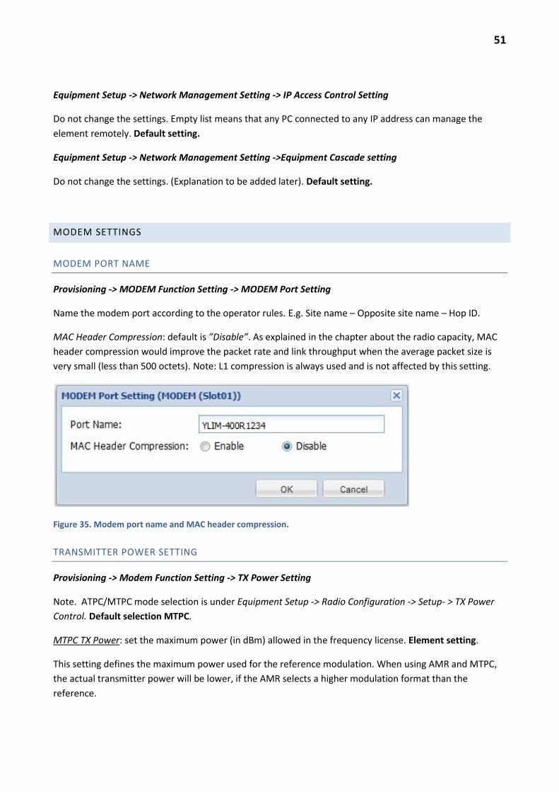
51
Equipment Setup -> Network Management Setting -> IP Access Control Setting
Do not change the settings. Empty list means that any PC connected to any IP address can manage the
element remotely. Default setting.
Equipment Setup -> Network Management Setting ->Equipment Cascade setting
Do not change the settings. (Explanation to be added later). Default setting.
MODEM SETTINGS
MODEM PORT NAME
Provisioning -> MODEM Function Setting -> MODEM Port Setting
Name the modem port according to the operator rules. E.g. Site name – Opposite site name – Hop ID.
MAC Header Compression: default is ”Disable”. As explained in the chapter about the radio capacity, MAC
header compression would improve the packet rate and link throughput when the average packet size is
very small (less than 500 octets). Note: L1 compression is always used and is not affected by this setting.
Figure 35. Modem port name and MAC header compression.
TRANSMITTER POWER SETTING
Provisioning -> Modem Function Setting -> TX Power Setting
Note. ATPC/MTPC mode selection is under Equipment Setup -> Radio Configuration -> Setup- > TX Power
Control. Default selection MTPC.
MTPC TX Power: set the maximum power (in dBm) allowed in the frequency license. Element setting.
This setting defines the maximum power used for the reference modulation. When using AMR and MTPC,
the actual transmitter power will be lower, if the AMR selects a higher modulation format than the
reference.
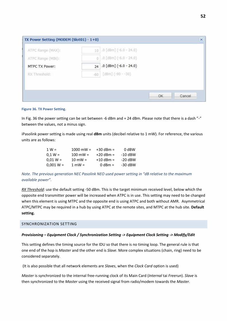
52
Figure 36. TX Power Setting.
In Fig. 36 the power setting can be set between -6 dBm and + 24 dBm. Please note that there is a dash ”-”
between the values, not a minus sign.
iPasolink power setting is made using real dBm units (decibel relative to 1 mW). For reference, the various
units are as follows:
1 W = 1000 mW = +30 dBm = 0 dBW 0,1 W = 100 mW = +20 dBm = -10 dBW 0,01 W = 10 mW = +10 dBm = -20 dBW 0,001 W = 1 mW = 0 dBm = -30 dBW
Note. The previous generation NEC Pasolink NEO used power setting in “dB relative to the maximum
available power”.
RX Threshold: use the default setting -50 dBm. This is the target minimum received level, below which the
opposite end transmitter power will be increased when ATPC is in use. This setting may need to be changed
when this element is using MTPC and the opposite end is using ATPC and both without AMR. Asymmetrical
ATPC/MTPC may be required in a hub by using ATPC at the remote sites, and MTPC at the hub site. Default
setting.
SYNCHRONIZATION SETTING
Provisioning – Equipment Clock / Synchronization Setting -> Equipment Clock Setting -> Modify/Edit
This setting defines the timing source for the IDU so that there is no timing loop. The general rule is that
one end of the hop is Master and the other end is Slave. More complex situations (chain, ring) need to be
considered separately.
(It is also possible that all network elements are Slaves, when the Clock Card option is used)
Master is synchronized to the internal free-running clock of its Main Card (Internal tai Freerun). Slave is
then synchronized to the Master using the received signal from radio/modem towards the Master.

53
If both ends are Master-Master or Slave-Slave, the connection will be unstable: errors and/or Unlocked
alarms. The element management may report ”Communications Error” when using the web browser.
Note. If a chain contains several iPasolink sites and the intermediate site is using a single IDU (two modems
per IDU), then the first IDU of the chain on the core network side should be Master and all the other IDUs
Slaves synchronized to the modem towards the Master. In this case there are several Slaves connected to
each other, but the timing is nevertheless derived indirectly from the Master IDU.
SETTINGS WITHOUT THE CLOCK CARD –OPTION
Without the Clock Card –option the setting is very simple, see Fig. 37-38. Three alternatives are available
Internal / MODEM/ Auto. Select Internal (= MASTER) at the other IDU and Modem (=SLAVE). Chain of IDUs;
see the note above. Element setting.
Figure 37. Slave setting without the Clock Module
Auto setting is used for the slave e.g. in a ring in order to select the clock automatically from the two
directions.

54
Figure 38. Master setting without the Clock Module.
SYNCHRONIZATION SETTINGS WITH THE CLOCK MODULE
The settings are presented in Fig. 39 and 40.
Figure 39. Master setting with the Clock Card -option.
Equipment Clock Setting – MASTER
Equipment CLK Mode: Master
Clock Source Selective Mode: QL Mode (Quality level).
Equipment Clock Setting – SLAVE
Equipment CLK Mode: Slave

55
Clock Source Selective Mode: PL Mode (Priority Level). (QL Mode could be used as well).
Select No.1 Line CLK (MODEM), and the Slot number where the modem towards Master is installed and
select Priority Level = 1.
In case of 1+1, select the two modems for Priority level 1 and 2.
Figure 40. Slave settings with the Clock Card –option
DATE AND TIME SETTING
The system may or may use NTP for the date and time setting. In any case the Date and Time should be set
initially, in order to time stamp the event logs correctly.
Equipment Utility -> Date / Time Setting -> Modify
Figure 41. Date and time setting.
Copy the PC time by selecting Display PC Time and press OK. Verify that the Time Zone is the same as is
used in the NMS server. Element setting.

56
NETWORK MANAGEMENT SECURITY SETTINGS
User Account/Security Setting -> Security Management -> Service Status Setting
Figure 42. Status of the management related services
”Service Status” window should look like Figure 42. Other services should be running except for the SFTP
and HTTPS stopped.
Figure 43. SNMP service settings

57
Figure 44. SNMP Community settings (no access control).
SNMP Community. Default setting: public/Admin/Access Control Disable (0.0.0.0/0.0.0.0).
The first line can be edited using the link 1. The Community name has to be the same as in the PNMSj
settings (public). Access Level = Admin. Source IP and mask 0.0.0.0 means that the Access Control is
Disabled). Default setting.
If access to the element has to be limited from a single NMS server IP address only: Source IP Address =
PNMSj-server IP address and Subnet Mask = 255.255.255.255. (Note! This is not the subnet mask where the
NMS server is situated but the mask for checking the address validity. Full mask checks all bits in the
address). It is possible to give Source IP Address = subnet address and the Subnet Mask = subnet mask. In
that case the server may have any address within the specified subnet.
Example: Source IP Address = 192.168.180.0 and Subnet Mask 255.255.255.0 => SNMP-message may
originate from any address within 192.168.180.1 to 192.168.180.254.
SNMP Trap Entry.
Normally empty, unless SNMP traps (alarms) are to be sent to another destination besides the NMS server.
Default setting.

58
NTP SETTINGS FOR THE ROOT ELEMENT
User Account/Security Setting -> Security Management -> Service Status Setting
Figure 45. NTP settings for the root element when the NTP server is at 192.168.180.36.
Most accurate time stamping of the events and logs etc. requires that an NTP server is available for the root
elements.
Figure 45 shows the settings for the root element. It is both a Client of the NTP server and a Server for the
normal elements. Unicast mode is used (i.e. using IP addresses to communicate).
NTP Version has to be the same as in the NTP server.
If there is no NTP server available in the management network, set the root element NTP Client Mode =
Disabled. In that case the root element clock (date and time) will slowly drift but the whole subnet (root
and its normal elements) remains locally synchronized.

59
NTP SETTINGS FOR NON-ROOT (NORMAL) ELEMENTS
User Account/Security Setting -> Security Management -> Service Status Setting
Figure 46. NTP settings for normal elements. NTP server is the root element modem (Bridge1) IP address.
For other elements than the root element the NTP Server Address is the root element Bridge1 address. The
NTP Server Mode is now Disabled.
Note. In a small network it would be possible to define all network elements as NTP Clients only and specify
the same NTP server for all elements. But in a large network it is better to use a hierarchical system where
only a limited number of root elements communicate with the NTP server and most elements get the time
from a lower level server (the root element in this case). The polling interval can then be much shorter
(more accurate clock) without overloading the NTP server and the DCN.

60
OTHER SERVICES
User Account/Security Setting -> Security Management -> Service Status Setting
Figure 47. FTP, SFTP, HTTP and HTTPS service settings
Note that the HTTP service should never be disabled as the web interface will be disabled and restoring
this setting would be impossible remotely. The SFTP and HTTPS services should be Stopped (either HTTP
or HTTPS should be running, not both). Default settings.
Figure 48. FTP settings.

61
ANTENNA ALIGNMENT
The basic settings described in the previous chapters should be done before the antenna alignment.
Before the alignment some temporary settings are required for correct receive level indication.
ALIGNMENT SETTINGS
If the element is already connected to the NMS server, set Maintenance on (Current Status top of
page). This will record in the logs that some maintenance operation is going on causing RX level
changes and alarms
Under Equipment Setup -> Radio Configuration -> Setup verify that the reference modulation is set
QSPK
Check that the power setting is manual: Equipment Setup -> Radio Configuration -> Setup -> TX
Power Control = ”MTPC”.
Under Equipment Setup -> AMR Configuration set AMR to (”Non Operation”).
Set the maximum power under Provisioning -> Modem Function Setting -> TX Power Setting.
These settings have to be done at both ends of the hop before the alignment. Note that the local settings
affect the RX level measurement at the remote end. Remember to restore the correct settings after the
alignment.
Note: depending on the local regulations, the use of maximum power during the alignment may be
prohibited. In any case the risk of interference to another link is minimal, when the alignment is done
quickly. The victim receiver must experience a rare deep rain or multipath fade during the alignment in
order to cause problems and therefore increasing power for a short period of time should not cause any
problems to other hops.
RECEIVER LEVEL MEASUREMENT
The ODU has an F-type female connector for the level monitoring. The voltage is available at all times.
There is no setting to switch the voltage off or on.
A typical calibration curve is presented in Figure 49. Before climbing to the ODU it is wise to check the
target voltage level. E.g. -45 dBm equals about 2,8V.

62
Figure 49. Typical connector voltage vs. receiver level at the ODU antenna port
A typical mistake during the alignment is to find the first side lobe of the pattern. Note that the side lobes
are circular around the round main lobe, when looking behind the antenna. The minima between the
maxima are also circular. See Figure 50.
Figure 50. Antenna lobes are circular. First side lobe may be confused with the main lobe.

63
While aligning the antenna at one end, the other end antenna must not be moved. After the main lobe has
been found at one end the other end is aligned. Finally the correct level is verified at both ends.
The alignment is correct when there are two lower side lobes next to maximum both in the elevation and in
the azimuth direction.
HOP ATTENUATION VERIFICATION
Under Metering -> Current Metering the received level is indicated in dBm as well as the current transmit
power in dBm.
Verify that the difference between the remote transmit power and the local received level is the
same as in the hop calculation. The difference (hop attenuation) should be correct within a few dB
(+-2 dB).
If the hop attenuation is not correct within the tolerance, check first the weather conditions. During rain
(typically >10 GHz) or clear air multipath fading (typically < 13 GHz and long hop > 20 km) the attenuation
may be temporarily very high and unstable. If the temporary weather is not the reason any permanent
cause (obstacle, reflection, antenna misalignment) has to be removed. Consult with the hop planner. Too
high hop attenuation means that the fade margin is not as good as planned and the availability and error
performance targets will not be met.
Restore the correct settings if they were changed for the alignment.
Reset the PMON counters and clear the event logs. Maintenance Control/PMON/RMON FDB Clear
and Equipment Utility/Log Clear Function.
MANAGEMENT NETWORK
The management system for NEC Pasolink/iPasolink called PNMSj. Alternatively the more generic MS5000
can be used. The DCN is based on Ethernet/IP/TCP/UDP/SNMP.
Each cluster of radio links is usually connected to the NMS DCN at one IDU (the root element).
The root element is connected to the DCN using the NMS port or using a VLAN in the traffic port (in-band
connection).
The other elements are connected to the root element or other element over-the-air or using NMS/NE1 to
NMS/NE1 Ethernet cabling between two IDUs at the same site.
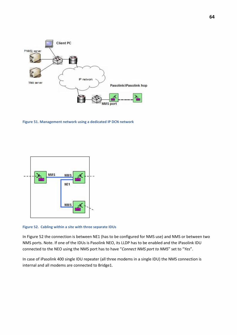
64
Figure 51. Management network using a dedicated IP DCN network
Figure 52. Cabling within a site with three separate IDUs
In Figure 52 the connection is between NE1 (has to be configured for NMS use) and NMS or between two
NMS ports. Note. If one of the IDUs is Pasolink NEO, its LLDP has to be enabled and the iPasolink IDU
connected to the NEO using the NMS port has to have “Connect NMS port to NMS” set to “Yes”.
In case of iPasolink 400 single IDU repeater (all three modems in a single IDU) the NMS connection is
internal and all modems are connected to Bridge1.

65
DCN OVER PDH/SDH
If there is no Ethernet/IP DCN network available to any station in the iPasolink cluster, it is possible use PDH
network for DCN (“Ethernet over PDH”). At least one E1 should be dedicated to the NMS traffic per
iPasolink cluster. RAD Egate with remote RICi units has been used successfully for this purpose. Egate has
an Ethernet interface to the NMS DCN and an STM-1 interface to the SDH/PDH network. One E1 carries the
NMS traffic through the network to the remote cluster where an RICi unit is used to convert the E1 back to
an Ethernet port connected to the root iPasolink NMS port.
MANAGEMENT USING METRO ETHERNET VPLS SERVICE
One possible solution to connect the DCN to iPasolink is to use the Metro Ethernet to carry the DCN as a
VPLS service. This solution will keep the DCN network separated from the Metro customer traffic.
Figure 53. Management connection using VPLS over Metro network
The advantage of using VPLS (as opposed to point to point VPN) is that a single Metro port at site X may
serve many tens of microwave sites (site A, B,.. etc).
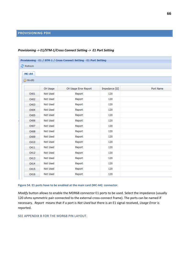
66
PROVISIONING PDH
Provisioning -> E1/STM-1/Cross Connect Setting -> E1 Port Setting
Figure 54. E1 ports have to be enabled at the main card (MC-A4) connector.
Modify button allows to enable the MDR68 connector E1 ports to be used. Select the impedance (usually
120 ohms symmetric pair connected to the external cross-connect frame). The ports can be named if
necessary. Report means that if a port is Not Used but there is an E1 signal received, Usage Error is
reported.
SEE APPENDIX B FOR THE MDR68 PIN LAYOUT.
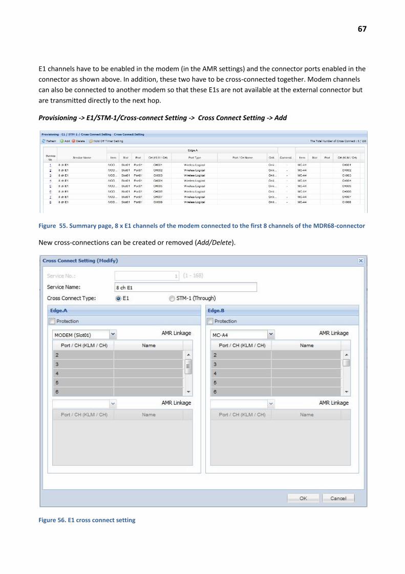
67
E1 channels have to be enabled in the modem (in the AMR settings) and the connector ports enabled in the
connector as shown above. In addition, these two have to be cross-connected together. Modem channels
can also be connected to another modem so that these E1s are not available at the external connector but
are transmitted directly to the next hop.
Provisioning -> E1/STM-1/Cross-connect Setting -> Cross Connect Setting -> Add
Figure 55. Summary page, 8 x E1 channels of the modem connected to the first 8 channels of the MDR68-connector
New cross-connections can be created or removed (Add/Delete).
Figure 56. E1 cross connect setting

68
Select one channel on the Edge A side and another on the Edge B side and press OK. Repeat for additional
connections. Block selection is also possible. Element setting.
Note. Under Equipment Setup -> AMR/ Radio Mapping Configuration the number of E1 channels carried by
the radio were set for each AMR level. If the modem E1 channel setting is changed then the extra cross
connections are removed automatically.
Hold-off Timer Setting. Default is ”Disable”. Default setting.
AMR Linkage shows how many E1 channels are available at each modulation level.
Figure 57. AMR E1 priority status. Lower channel number has higher priority.

69
ETHERNET SETTINGS
Provisioning -> ETH Function Setting
The Menu contains numerous L2 switch settings under Eth Function Setting. This chapter describes the
most common settings only.
Interface numbering
Ethernet ports are identified by the main card (MC-A4) or by the card type/slot number (GbE-A/Slot 1) as
well as the port number (Port01). Positions and ports are numbered from left to right. Port 1 and 2 are
electrical and port 3 and 4 are SFP slots.
Limitation: each card (MC-A4 or GbE-A) accepts only one type of SFP at a time. Port 3 and port 4 have to
have the same SFP inserted or port 4 has to be empty.
Bridge Setting
Figure 58 shows the recommended settings which should not be changed.
Note. The VLAN Mode (802.1Q tai 802.1ad) has to be identical in all IDUs in a cluster. Differing settings will
prevent remote management and connection to NMS.
Figure 58. L2 switch basic settings.
ETH Port Setting
Ethernet ports can be opened (Enable) and removed from use (Disable). The ports can be named.

70
Figure 59. In this figure MC-A4 2nd port has been given a name ”TRUNK” and it has been enabled. The cable is
disconnected (Link Down).
The correct Ethernet settings depend on the external equipment settings.
Figure 60. GbE settings. Note. Optical SPF allows selecting ”Electrical” but that will cause an alarm.
VLAN SETTINGS
VLAN Setting
”VLAN List” tab: create here first the VLAN ID numbers and names. Element setting.

71
Figure 61. VLAN settings.
The VLANs can be assigned to ports in the VLAN Setting tab.
Figure 62. Example VLAN settings. Each external port has a tunnel VLAN and the modem port allows traffic of these
VLANs (as trunks).
VLAN Port Type setting selects how the incoming (Ingress) and outgoing (Egress) frames are handled. The
VLAN port types are explained first. Type selection available depends on the BRIDGE (VLAN) mode.
The simplest way is to use the 802.1q –mode and tunnelling. The remote site has one or more physical
ports each with a single VLAN tunnel. In the modems and at repeater sites the VLANs are forwarded using
trunk ports. The traffic can be aggregated to single trunk port or each tunnel can be terminated in a
separate physical port (see Figure 65 – 66).
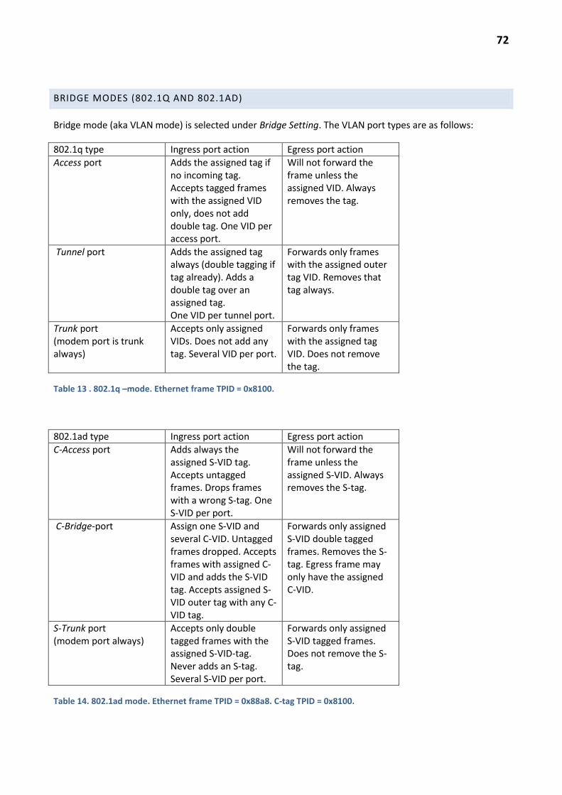
72
BRIDGE MODES (802.1Q AND 802.1AD)
Bridge mode (aka VLAN mode) is selected under Bridge Setting. The VLAN port types are as follows:
802.1q type Ingress port action Egress port action
Access port
Adds the assigned tag if no incoming tag. Accepts tagged frames with the assigned VID only, does not add double tag. One VID per access port.
Will not forward the frame unless the assigned VID. Always removes the tag.
Tunnel port
Adds the assigned tag always (double tagging if tag already). Adds a double tag over an assigned tag. One VID per tunnel port.
Forwards only frames with the assigned outer tag VID. Removes that tag always.
Trunk port (modem port is trunk always)
Accepts only assigned VIDs. Does not add any tag. Several VID per port.
Forwards only frames with the assigned tag VID. Does not remove the tag.
Table 13 . 802.1q –mode. Ethernet frame TPID = 0x8100.
802.1ad type Ingress port action Egress port action
C-Access port
Adds always the assigned S-VID tag. Accepts untagged frames. Drops frames with a wrong S-tag. One S-VID per port.
Will not forward the frame unless the assigned S-VID. Always removes the S-tag.
C-Bridge-port
Assign one S-VID and several C-VID. Untagged frames dropped. Accepts frames with assigned C-VID and adds the S-VID tag. Accepts assigned S-VID outer tag with any C-VID tag.
Forwards only assigned S-VID double tagged frames. Removes the S- tag. Egress frame may only have the assigned C-VID.
S-Trunk port (modem port always)
Accepts only double tagged frames with the assigned S-VID-tag. Never adds an S-tag. Several S-VID per port.
Forwards only assigned S-VID tagged frames. Does not remove the S- tag.
Table 14. 802.1ad mode. Ethernet frame TPID = 0x88a8. C-tag TPID = 0x8100.

73
It is possible to create several VLAN ports in the same physical port with certain limitations. As an example,
802.1q trunk-port (VID= 100) and access-port (VID=200) may coexist in an Ethernet port. The port will then
accept VID=100 tagged frames as well as VID=200 tagged frames. All untagged frames will also be accepted
and a tag with VID=200 is added to them. Modem ports can only use trunk VLANs.
SAMPLE VLAN SETTINGS
Provisioning -> ETH Function Setting -> VLAN Setting -> VLAN List ”+ Add VLAN ID”.
Create VID = 100, name ”Elisa”; VID = 300, name ”Sonera 3G”; VID = 400, name ”Sonera 4G”. See Figure 63.
Figure 63. VLAN List.
Now assign these VLAN IDs to Ethernet ports, type ”802.1q Tunnel”. Add all the VLAN IDs to the modem
port (Trunk).
Figure 64. VLAN settings in a sample case.
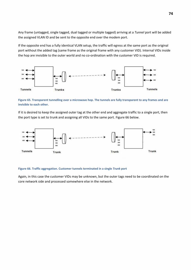
74
Any frame (untagged, single tagged, dual tagged or multiple tagged) arriving at a Tunnel port will be added
the assigned VLAN ID and be sent to the opposite end over the modem port.
If the opposite end has a fully identical VLAN setup, the traffic will egress at the same port as the original
port without the added tag (same frame as the original frame with any customer VID). Internal VIDs inside
the hop are invisible to the outer world and no co-ordination with the customer VID is required.
Figure 65. Transparent tunnelling over a microwave hop. The tunnels are fully transparent to any frames and are
invisible to each other.
If it is desired to keep the assigned outer tag at the other end and aggregate traffic to a single port, then
the port type is set to trunk and assigning all VIDs to the same port. Figure 66 below.
Figure 66. Traffic aggregation. Customer tunnels terminated in a single Trunk port
Again, in this case the customer VIDs may be unknown, but the outer tags need to be coordinated on the
core network side and processed somewhere else in the network.

75
Figure 67. Settings for Figure 66 trunk Ethernet port. All three VLANs are assigned to the same trunk port (MC-A4
Port 02).
FDB Setting
Forwarding Data Base contains the L2 switch MAC-address settings.
Retrieve Current FDB – check and store the MAC-addresses e.g. for trouble shooting. Use a Microsoft
application to open the file (e.g. Word, WordPad or Excel) to see the file in a readable format.
Ethernet OAM Setting
This is a complex collection of settings not explained in this document version.
RSTP Setting
In simple networks consisting of linear and branching point to point links this setting is not required. STP
Mode = Disable.
Link Aggregation Setting
Normally there are no LAG groups unless the Ethernet connection from the IDU to an external switch needs
to be redundant (use dual cables and interfaces) or unless single cable capacity is not sufficient (e.g. 2 x FE
ports only available in the external switch). The LAG group will balance the traffic (with limitations)
between the two ports.
ERP Setting
Ethernet Ring Protection is not addressed by this document version.

76
QOS SETTINGS
Provisioning - > Ethernet Function Setting -> QoS/Classification Setting
Each port of the iPasolink L2 switch can be configured for certain QoS settings. The next section describes
the principles of iPasolink QoS operation in general.
TRAFFIC CLASSIFICATION PRINCIPLES
The functional QoS block diagram of the IDU is presented in Figure 68 below. Table 15 contains a summary
of the functions and associated settings.
Figure 68. QoS block diagram. The superscripts refer to the text.
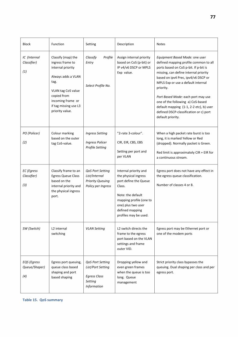
77
Block Function Setting Description Notes
IC (Internal
Classifier)
(1)
Classify (map) the
ingress frame to
internal priority
Always adds a VLAN
tag.
VLAN tag CoS value
copied from
incoming frame or
if tag missing use L3
priority value.
Classify Profile
Entry
Select Profile No.
Assign internal priority
based on CoS (p-bit) or
IP v4/v6 DSCP or MPLS
Exp value.
Equipment Based Mode: one user
defined mapping profile common to all
ports based on CoS p-bit. If p-bit is
missing, can define internal priority
based on ipv4 Prec, ipv4/v6 DSCP or
MPLS Exp or use a default internal
priority.
Port Based Mode: each port may use
one of the following a) CoS-based
default mapping (1-1, 2-2 etc), b) user
defined DSCP-classification or c) port
default priority.
PO (Policer)
(2)
Colour marking
based on the outer
tag CoS-value.
Ingress Setting
Ingress Policer
Profile Setting
”2-rate 3-colour”.
CIR, EIR, CBS, EBS
Setting per port and
per VLAN
When a high packet rate burst is too
long, it is marked Yellow or Red
(dropped). Normally packet is Green.
Red limit is approximately CIR + EIR for
a continuous stream.
EC (Egress
Classifier)
(3)
Classify frame to an
Egress Queue Class
based on the
internal priority and
the physical ingress
port.
QoS Port Setting
List/Internal
Priority Queuing
Policy per Ingress
Internal priority and
the physical ingress
port define the Queue
Class.
Note: the default
mapping profile (one to
one) plus two user
defined mapping
profiles may be used.
Egress port does not have any effect in
the egress queue classification.
Number of classes 4 or 8.
SW (Switch) L2 internal
switching
VLAN Setting L2 switch directs the
frame to the egress
port based on the VLAN
settings and frame
outer VID.
Egress port may be Ethernet port or
one of the modem ports
EQS (Egress
Queue/Shaper)
(4)
Egress port queuing,
queue class based
shaping and port
based shaping
QoS Port Setting
List/Port Setting
Egress Class
Setting
Information
Dropping yellow and
even green frames
when the queue is too
long. Queue
management
Strict priority class bypasses the
queuing. Dual shaping per class and per
egress port.
Table 15. QoS summary

78
The Qos processing of frames consists of four phases from ingress port (e.g. Ethernet port) to egress port
(e.g. modem port). The process is similar in the reverse direction but the QoS settings may be totally
different (Figure 68).
1) Incoming or ingress frames are classified into an internal priority value (”IC” in Figure 68) based on
customer VLAN-tag L2 priority (p-bit) value or
customer L3 priority value (IPv4 tai IPv6 DSCP) or
MPLS Exp –priority value.
The classification is to internal priority. In this phase, if a VLAN tag is added, the CoS value is copied or if
missing, the CoS value is based on the internal priority classification.
In the Port Based QoS –mode the VLAN-tag priority is copied as such from the internal priority. In this
mode VLAN-frames can be classified internally based on IP v4 or IP v6 DSCP-priority using the default
mapping: VLAN CoS value is not used but the DSCP value. The outer tag CoS value is always copied from
the inner tag, however. (This will change in a later version). If the ingress frame has no tag, the CoS value is
the internal priority.
In the Equipment Based QoS mode the VLAN tag p-bit will always decide the internal priority over any L3
priority and it can be mapped as wanted to the internal priority (single profile for all ports). If the frame has
no VLAN tag, it is possible to select IP v4 Precedence, IP v4 DCSP, IP v6 DSCP tai MPLS Exp –value based
internal priority which is also the VLAN tag CoS value. In this mode the classification is common to all ports
of the IDU.
The third available mode is VLAN ID Based QoS Mode. Internal priority is based on the VID only, nothing
else.
Note that the ingress frame priority classification into internal priority is also applicable to the modem port.
2) In the second phase, the frame is Ingress Policer classified based on outer tag CoS value (original or
added tag). ”PO” in Figure 68. Ingress Setting tab (Figure 69).
Total 16 Policer profiles can be added. Define CIR (Committed Information Rate), EIR (Excessive Information
Rate, i.e. tolerance above CIR) as well as EBS (Excessive Burst Size, EBS kbyte) and CBS (Committed Burst
Size, CBS kbyte). The burst sizes and the rates define when the frame is marked Yellow or Red (and dropped
immediately).
Note. RFC4115 implementation in iPasolink is such that PIR (Peak Information Rate) = CIR+EIR is the limit
when the frames are marked Red based on the EBS setting. As an example CIR = 100 Mbit/s and EIR = 50
Mbit/s will transmit almost 150 Mbit/s continuously.
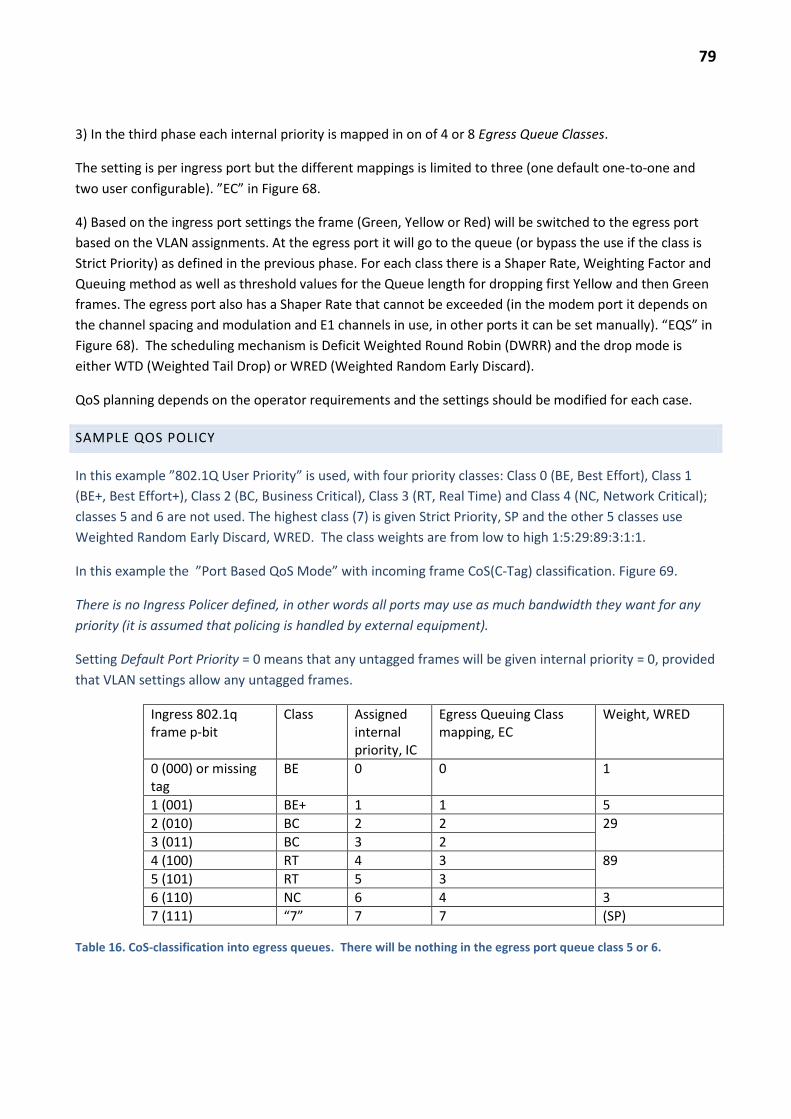
79
3) In the third phase each internal priority is mapped in on of 4 or 8 Egress Queue Classes.
The setting is per ingress port but the different mappings is limited to three (one default one-to-one and
two user configurable). ”EC” in Figure 68.
4) Based on the ingress port settings the frame (Green, Yellow or Red) will be switched to the egress port
based on the VLAN assignments. At the egress port it will go to the queue (or bypass the use if the class is
Strict Priority) as defined in the previous phase. For each class there is a Shaper Rate, Weighting Factor and
Queuing method as well as threshold values for the Queue length for dropping first Yellow and then Green
frames. The egress port also has a Shaper Rate that cannot be exceeded (in the modem port it depends on
the channel spacing and modulation and E1 channels in use, in other ports it can be set manually). “EQS” in
Figure 68). The scheduling mechanism is Deficit Weighted Round Robin (DWRR) and the drop mode is
either WTD (Weighted Tail Drop) or WRED (Weighted Random Early Discard).
QoS planning depends on the operator requirements and the settings should be modified for each case.
SAMPLE QOS POLICY
In this example ”802.1Q User Priority” is used, with four priority classes: Class 0 (BE, Best Effort), Class 1
(BE+, Best Effort+), Class 2 (BC, Business Critical), Class 3 (RT, Real Time) and Class 4 (NC, Network Critical);
classes 5 and 6 are not used. The highest class (7) is given Strict Priority, SP and the other 5 classes use
Weighted Random Early Discard, WRED. The class weights are from low to high 1:5:29:89:3:1:1.
In this example the ”Port Based QoS Mode” with incoming frame CoS(C-Tag) classification. Figure 69.
There is no Ingress Policer defined, in other words all ports may use as much bandwidth they want for any
priority (it is assumed that policing is handled by external equipment).
Setting Default Port Priority = 0 means that any untagged frames will be given internal priority = 0, provided
that VLAN settings allow any untagged frames.
Ingress 802.1q frame p-bit
Class Assigned internal priority, IC
Egress Queuing Class mapping, EC
Weight, WRED
0 (000) or missing tag
BE 0 0 1
1 (001) BE+ 1 1 5
2 (010) BC 2 2 29
3 (011) BC 3 2
4 (100) RT 4 3 89
5 (101) RT 5 3
6 (110) NC 6 4 3
7 (111) “7” 7 7 (SP)
Table 16. CoS-classification into egress queues. There will be nothing in the egress port queue class 5 or 6.
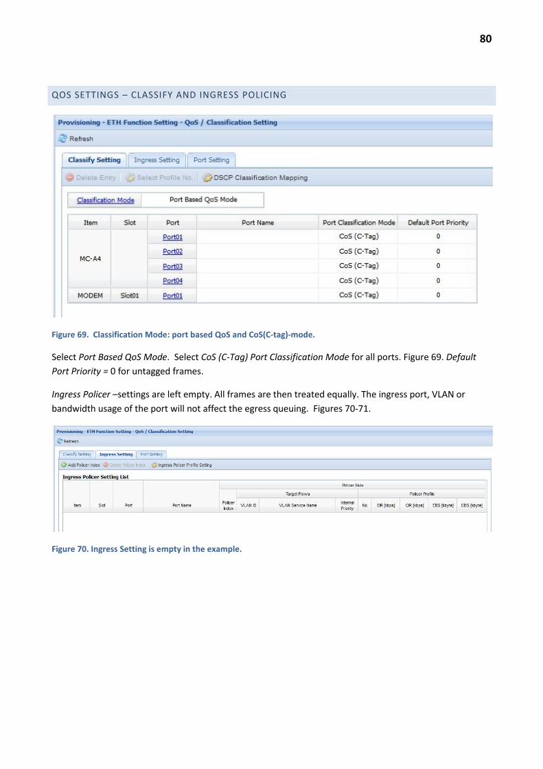
80
QOS SETTINGS – CLASSIFY AND INGRESS POLICING
Figure 69. Classification Mode: port based QoS and CoS(C-tag)-mode.
Select Port Based QoS Mode. Select CoS (C-Tag) Port Classification Mode for all ports. Figure 69. Default
Port Priority = 0 for untagged frames.
Ingress Policer –settings are left empty. All frames are then treated equally. The ingress port, VLAN or
bandwidth usage of the port will not affect the egress queuing. Figures 70-71.
Figure 70. Ingress Setting is empty in the example.

81
Figure 71. Add Policer Index: here Policer Profile would be selected if necessary.
Under Provisioning -> ETH Function Setting -> QoS / Classification Setting -> Port Setting the Class Mode
is selected, following the example 8 classes. Figure 72. This setting is common for all ports including the
modem.
Figure 72. Class Mode Setting (number of egress queues in each port).

82
PORT QOS SETTINGS
The settings for the QoS policy example are described here.
Table 16 shows one-to-one mapping from CoS to internal priority which is the default setting in the Port
Based QoS Mode and cannot be changed in this mode. The settings for each ingress port have to be
modified: mapping from internal priority to egress queue class, scheduling, shaping and WRED-settings.
Figure 73. QoS Port Setting List.
The egress port queuing class for each ingress frame is set based on the ingress port and the internal
priority in tab Port Setting.
The summary page right side Class Info /Detail link opens the Egress Class Detail settings for that port
(Figure 74). Further, the Class number link opens the Egress Class Setting (Figure 75). The Port-link on the
summary page (Fig. 73) opens the port settings (Figure 76).
Figure 74. Summary of the port Egress settings. Edit each class settings using the link.
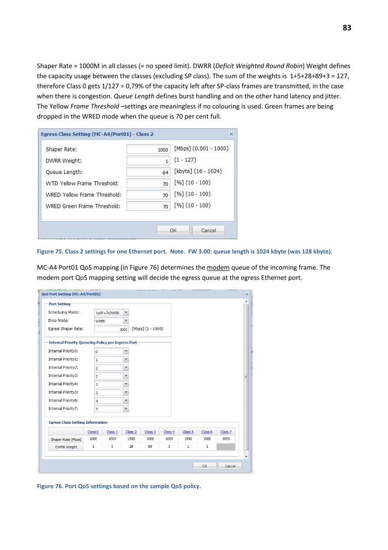
83
Shaper Rate = 1000M in all classes (= no speed limit). DWRR (Deficit Weighted Round Robin) Weight defines
the capacity usage between the classes (excluding SP class). The sum of the weights is 1+5+28+89+3 = 127,
therefore Class 0 gets 1/127 = 0,79% of the capacity left after SP-class frames are transmitted, in the case
when there is congestion. Queue Length defines burst handling and on the other hand latency and jitter.
The Yellow Frame Threshold –settings are meaningless if no colouring is used. Green frames are being
dropped in the WRED mode when the queue is 70 per cent full.
Figure 75. Class 2 settings for one Ethernet port. Note. FW 3.00: queue length is 1024 kbyte (was 128 kbyte).
MC-A4 Port01 QoS mapping (in Figure 76) determines the modem queue of the incoming frame. The
modem port QoS mapping setting will decide the egress queue at the egress Ethernet port.
Figure 76. Port QoS settings based on the sample QoS policy.
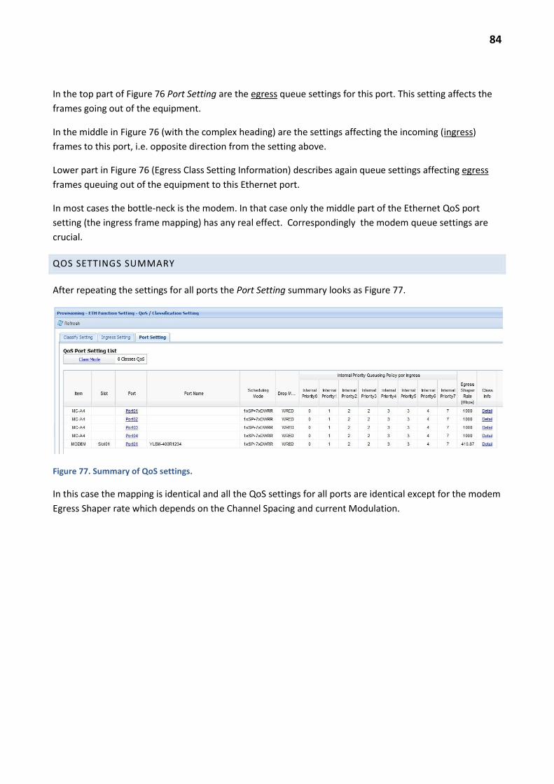
84
In the top part of Figure 76 Port Setting are the egress queue settings for this port. This setting affects the
frames going out of the equipment.
In the middle in Figure 76 (with the complex heading) are the settings affecting the incoming (ingress)
frames to this port, i.e. opposite direction from the setting above.
Lower part in Figure 76 (Egress Class Setting Information) describes again queue settings affecting egress
frames queuing out of the equipment to this Ethernet port.
In most cases the bottle-neck is the modem. In that case only the middle part of the Ethernet QoS port
setting (the ingress frame mapping) has any real effect. Correspondingly the modem queue settings are
crucial.
QOS SETTINGS SUMMARY
After repeating the settings for all ports the Port Setting summary looks as Figure 77.
Figure 77. Summary of QoS settings.
In this case the mapping is identical and all the QoS settings for all ports are identical except for the modem
Egress Shaper rate which depends on the Channel Spacing and current Modulation.
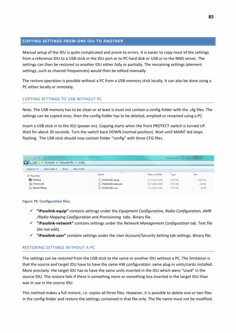
85
COPYING SETTINGS FROM ONE IDU TO ANOTHER
Manual setup of the IDU is quite complicated and prone to errors. It is easier to copy most of the settings
from a reference IDU to a USB-stick in the IDU port or to PC hard disk or USB or to the NMS server. The
settings can then be restored to another IDU either fully or partially. The remaining settings (element
settings, such as channel frequencies) would then be edited manually.
The restore operation is possible without a PC from a USB-memory stick locally. It can also be done using a
PC either locally or remotely.
COPYING SETTINGS TO USB WITHOUT PC
Note. The USB memory has to be clean or at least is must not contain a config-folder with the .cfg files. The
settings can be copied once, then the config-folder has to be deleted, emptied or renamed using a PC.
Insert a USB stick in to the IDU (power on). Copying starts when the front PROTECT-switch is turned UP.
Wait for about 30 seconds. Turn the switch back DOWN (normal position). Wait until MAINT led stops
flashing. The USB stick should now contain folder “config” with three CFG-files.
Figure 78. Configuration files.
”iPasolink-equip” contains settings under the Equipment Configuration, Radio Configuration, AMR
/Radio Mapping Configuration and Provisioning tabs. Binary file.
”iPasolink-network” contains settings under the Network Management Configuration tab. Text file
(do not edit).
”iPasolink-user” contains settings under the User Account/Security Setting tab settings. Binary file.
RESTORING SETTINGS WITHOUT A PC
The settings can be restored from the USB stick to the same or another IDU without a PC. The limitation is
that the source and target IDU have to have the same HW configuration: same plug-in units/cards installed.
More precisely: the target IDU has to have the same units inserted in the IDU which were “Used” in the
source IDU. The restore fails if there is something more or something less inserted in the target IDU than
was in use in the source IDU.
This method makes a full restore, i.e. copies all three files. However, it is possible to delete one or two files
in the config-folder and restore the settings contained in that file only. The file name must not be modified.

86
Turn off the target IDU. Wait for at least 10 seconds. Insert the USB stick with config folder and the CFG-
files into the USB port of the IDU. Turn the PROTECT switch UP. Now reconnect DC-power to the IDU. Wait
for about 2 minutes until the MAINT led stops flashing but remains ON. Now turn the PROTECT switch back
DOWN (normal position). After one minute the MAINT led will start flashing again (rebooting). Wait one
more minute until the MAINT led stops flashing and remains OFF. Remove the USB stick now. The IDU
should now operate using the settings copied from the USB folder.
COPYING SETTINGS USING THE BROWSER
Equipment Utility -> Export (NE -> Storage) Utility
Figure 79. Copying (export) settings to the local PC
Select e.g. Equipment Config Data and press Execute. Browser window opens, select Save File and select a
suitable folder and save the file.
If the IDU USB port has a USB stick inserted, it is possible to select Export to USB Memory. Press Execute
and wait for window “Complete” and press OK.
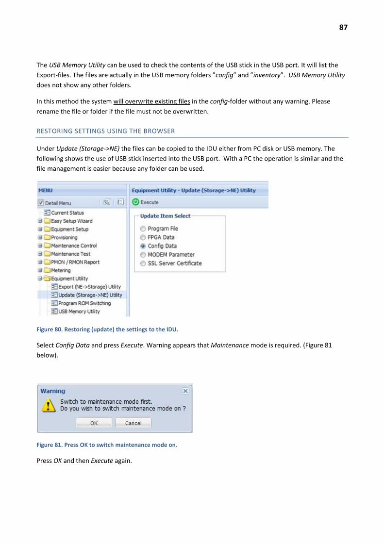
87
The USB Memory Utility can be used to check the contents of the USB stick in the USB port. It will list the
Export-files. The files are actually in the USB memory folders ”config” and ”inventory”. USB Memory Utility
does not show any other folders.
In this method the system will overwrite existing files in the config-folder without any warning. Please
rename the file or folder if the file must not be overwritten.
RESTORING SETTINGS USING THE BROWSER
Under Update (Storage->NE) the files can be copied to the IDU either from PC disk or USB memory. The
following shows the use of USB stick inserted into the USB port. With a PC the operation is similar and the
file management is easier because any folder can be used.
Figure 80. Restoring (update) the settings to the IDU.
Select Config Data and press Execute. Warning appears that Maintenance mode is required. (Figure 81
below).
Figure 81. Press OK to switch maintenance mode on.
Press OK and then Execute again.

88
Figure 82. Partial Restore.
The window (Figure 82) allows selection of e.g. Partial Equipment Config and Import File/USB Memory,
further click the folder symbol to the right of USB Memory line. A new window opens. (Figure 83). Select in
the USB stick the config/iPASOLINK-equip.cfg file and click OK. Note that the system does not see any
other folders than the config and inventory folders. In this method the file name does not matter as far it is
xxx.cfg and contains the correct data.
Figure 83. File selection.
Select the proper file and OK. Continue Next> (Figure 84).
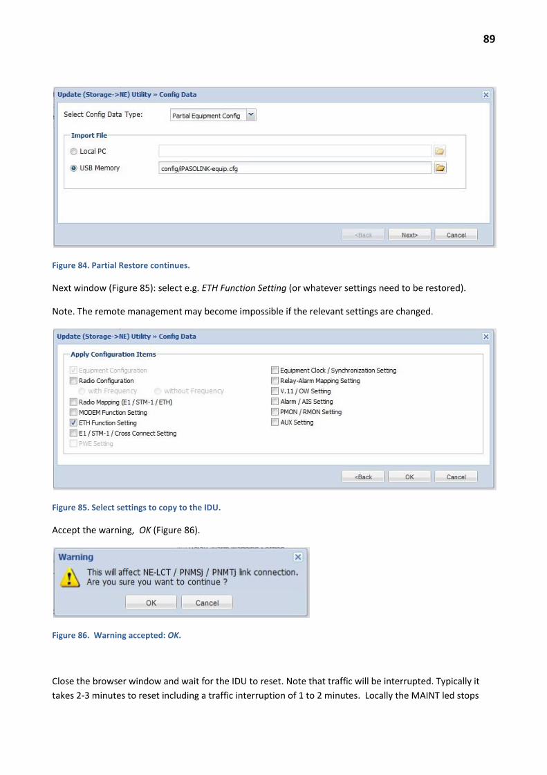
89
Figure 84. Partial Restore continues.
Next window (Figure 85): select e.g. ETH Function Setting (or whatever settings need to be restored).
Note. The remote management may become impossible if the relevant settings are changed.
Figure 85. Select settings to copy to the IDU.
Accept the warning, OK (Figure 86).
Figure 86. Warning accepted: OK.
Close the browser window and wait for the IDU to reset. Note that traffic will be interrupted. Typically it
takes 2-3 minutes to reset including a traffic interruption of 1 to 2 minutes. Locally the MAINT led stops

90
flashing and remains OFF when the IDU has rebooted. The traffic should return to normal very soon
thereafter.
In some cases the PC LAN card has to be reset (disable/enable) after the IDU reset in order to reconnect to
the LCT port. Do not pull the DC power while the IDU is resetting (MAINT led flashing).
Note. Ethernet settings restore (Partial Equipment Config) has the limitation that the source and target IDUs
have to be identically equipped. See also “Restoring Settings without a PC”.
PRECONFIGURATION FILES
Appendix D is a Quick Guide: how to install a new IDU when the common default settings have been
prepared in a reference IDU in advance. Most of the settings are copied to the new IDU using configuration
files.
If the IDU will use more cards than the reference IDU, these cards have to be physically removed before
copying the CFG-files to the IDU. The additional cards should then be reinserted and their settings done
manually as described in Appendix D and the rest of this document.

91
KNOWN PROBLEMS
CANNOT CONNECT THE BROWSER TO THE LCT PORT
Check that the PC LAN card is enabled and that the settings are correct (automatic IP address using
DHCP).
Check that the PC LAN card has the IP address in the same subnet as the LCT port (172.17.254.xxx).
Check that the LCT-port IP-address in the browser is the same as the PC LAN card ”default
gateway” which is always 172.17.254.253.
Try removing the PC LAN card physically or disable/enable it using the Control Panel.
Check that pop ups are allowed in the browser.
Lower security settings in the browser: Security Settings = Low.
Disable the PC firewall – this should never be a problem, however.
Remove and reinstall the PC LAN card driver – this will return the card to default settings.
CANNOT ACCESS REMOTE IDU OR ”COMMUNICATION ERROR”
If the pull down menu for the opposite IDU is empty, refresh the browser window (F5)
Check that the hop is OK (RX levels OK and BER = 0)
Verify Synchronization Settings: Master/Internal and opposite end is Slave/Modem. Check that the
Slave is configured to sync to the correct Master side modem, if more than one modem is in use.
Check the Bridge mode: identical in all IDUs in the cluster (e.g. 802.1q)
Verify that the modem is connected to Bridge1 port (in the NMS settings).
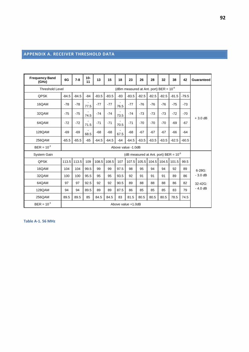
92
APPENDIX A. RECEIVER THRESHOLD DATA
Frequency Band (GHz)
6G 7-8 10-11
13 15 18 23 26 28 32 38 42 Guaranteed
Threshold Level (dBm measured at Ant. port) BER = 10-6
+ 3.0 dB
QPSK -84.5 -84.5 -84 -83.5 -83.5 -83 -83.5 -82.5 -82.5 -82.5 -81.5 -79.5
16QAM -78 -78 -
77.5 -77 -77
-76.5
-77 -76 -76 -76 -75 -73
32QAM -75 -75 -
74.5 -74 -74
-73.5
-74 -73 -73 -73 -72 -70
64QAM -72 -72 -
71.5 -71 -71
-70.5
-71 -70 -70 -70 -69 -67
128QAM -69 -69 -
68.5 -68 -68
-67.5
-68 -67 -67 -67 -66 -64
256QAM -65.5 -65.5 -65 -64.5 -64.5 -64 -64.5 -63.5 -63.5 -63.5 -62.5 -60.5
BER = 10-3 Above value -1.0dB
System Gain (dB measured at Ant. port) BER = 10-6
6-28G:
- 3.0 dB
32-42G:
- 4.0 dB
QPSK 113.5 113.5 109 108.5 108.5 107 107.5 105.5 104.5 104.5 101.5 99.5
16QAM 104 104 99.5 99 99 97.5 98 95 94 94 92 89
32QAM 100 100 95.5 95 95 93.5 92 91 91 91 89 86
64QAM 97 97 92.5 92 92 90.5 89 88 88 88 86 82
128QAM 94 94 89.5 89 89 87.5 86 85 85 85 83 79
256QAM 89.5 89.5 85 84.5 84.5 83 81.5 80.5 80.5 80.5 78.5 74.5
BER = 10-3 Above value +1.0dB
Table A-1. 56 MHz

93
Frequency Band (GHz)
6 7-8 10-11
13 15 18 23 26 28 32 38 42 Guaranteed
Threshold Level (dBm measured at Ant. port) BER = 10-6
+ 3.0 dB
QPSK -87.5 -87.5 -87 -86.5 -86.5 -86 -86.5 -85.5 -85.5 -85.5 -84.5 -82.5
16QAM -81 -81 -80.5 -80 -80 -79.5 -80 -79 -79 -79 -78 -76
32QAM -78 -78 -77.5 -77 -77 -76.5 -77 -76 -76 -76 -75 -73
64QAM -75 -75 -74.5 -74 -74 -73.5 -74 -73 -73 -73 -72 -70
128QAM -72 -72 -71.5 -71 -71 -70.5 -71 -70 -70 -70 -69 -67
256QAM -68.5 -68.5 -68 -67.5 -67.5 -67 -67.5 -66.5 -66.5 -66.5 -65.5 -63.5
BER = 10-3 Above value -1.0dB
System Gain (dB measured at Ant. port) BER = 10-6
6-28G:
- 3.0 dB
32-42G:
- 4.0 dB
QPSK 116.5 116.5 112 111.5 111.5 110 110.5 108.5 107.5 107.5 104.5 102.5
16QAM 108 108 103.5 103 103 101.5 102 99 98 98 96 93
32QAM 104 104 99.5 99 99 97.5 96 95 95 95 93 89
64QAM 101 101 96.5 96 96 94.5 93 92 92 92 90 86
128QAM 98 98 93.5 93 93 91.5 90 89 89 89 87 83
256QAM 93.5 93.5 89 88.5 88.5 87 85.5 84.5 84.5 84.5 82.5 78.5
BER = 10-3 Above value +1.0dB
Table A-2. 28 MHz

94
Frequency Band (GHz)
6 7-8 10-11
13 15 18 23 26 28 32 38 42 Guaranteed
Threshold Level (dBm measured at Ant. port) BER = 10-6
+ 3.0 dB
QPSK -90.5 -90.5 -90 -89.5 -89.5 -89 -89.5 -88.5 -88.5 -88.5 -87.5 -85.5
16QAM -84 -84 -83.5 -83 -83 -82.5 -83 -82 -82 -82 -81 -79
32QAM -81 -81 -80.5 -80 -80 -79.5 -80 -79 -79 -79 -78 -76
64QAM -78 -78 -77.5 -77 -77 -76.5 -77 -76 -76 -76 -75 -73
128QAM -75 -75 -74.5 -74 -74 -73.5 -74 -73 -73 -73 -72 -70
256QAM -71 -71 -70.5 -70 -70 -69.5 -70 -69 -69 -69 -68 -
BER = 10-3 Above value -1.0dB
System Gain (dB measured at Ant. port) BER = 10-6
6-28G:
- 3.0 dB
32-42G:
- 4.0 dB
QPSK 119.5 119.5 115 114.5 114.5 113 113.5 111.5 110.5 110.5 107.5 105.5
16QAM 111 111 106.5 106 106 104.5 105 102 101 101 99 96
32QAM 107 107 102.5 102 102 100.5 99 98 98 98 96 92
64QAM 104 104 99.5 99 99 97.5 96 95 95 95 93 89
128QAM 101 101 96.5 96 96 94.5 93 92 92 92 90 86
256QAM 96 96 91.5 91 91 89.5 88 87 87 87 85 -
BER = 10-3 Above value +1.0dB
Table A-3. 14 MHz
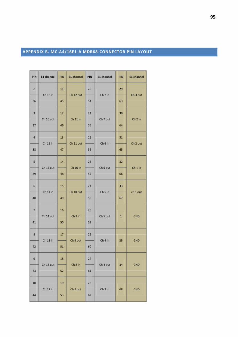
95
APPENDIX B. MC-A4/16E1-A MDR68-CONNECTOR PIN LAYOUT
PIN E1 channel PIN E1 channel PIN E1 channel PIN E1 channel
2
Ch 16 in
11
Ch 12 out
20
Ch 7 in
29
Ch 3 out
36 45 54 63
3
Ch 16 out
12
Ch 11 in
21
Ch 7 out
30
Ch 2 in
37 46 55 64
4
Ch 15 in
13
Ch 11 out
22
Ch 6 in
31
Ch 2 out
38 47 56 65
5
Ch 15 out
14
Ch 10 in
23
Ch 6 out
32
Ch 1 in
39 48 57 66
6
Ch 14 in
15
Ch 10 out
24
Ch 5 in
33
ch 1 out
40 49 58 67
7
Ch 14 out
16
Ch 9 in
25
Ch 5 out 1 GND
41 50 59
8
Ch 13 in
17
Ch 9 out
26
Ch 4 in 35 GND
42 51 60
9
Ch 13 out
18
Ch 8 in
27
Ch 4 out 34 GND
43 52 61
10
Ch 12 in
19
Ch 8 out
28
Ch 3 in 68 GND
44 53 62

96
APPENDIX C. MC-A4 D-SUB-44 CONNECTOR PIN LAYOUT
Figure C-1. MC-A4 –card (ALM/SC/CLK) connector pin layout.
V11 IDT is the input data and ODT is the output data.
For synchronous V.11: ICK is the clock input and OCK is the clock output. IFP and OFP are the input and
output for the frame timing, respectively.
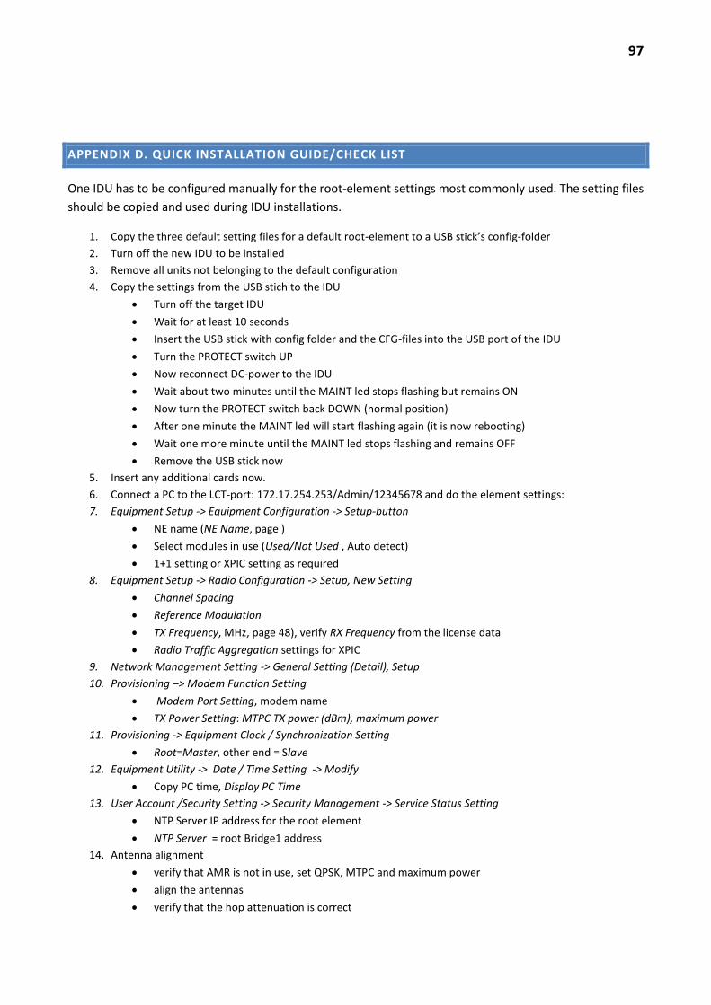
97
APPENDIX D. QUICK INSTALLATION GUIDE/CHECK LIST
One IDU has to be configured manually for the root-element settings most commonly used. The setting files
should be copied and used during IDU installations.
1. Copy the three default setting files for a default root-element to a USB stick’s config-folder
2. Turn off the new IDU to be installed
3. Remove all units not belonging to the default configuration
4. Copy the settings from the USB stich to the IDU
Turn off the target IDU
Wait for at least 10 seconds
Insert the USB stick with config folder and the CFG-files into the USB port of the IDU
Turn the PROTECT switch UP
Now reconnect DC-power to the IDU
Wait about two minutes until the MAINT led stops flashing but remains ON
Now turn the PROTECT switch back DOWN (normal position)
After one minute the MAINT led will start flashing again (it is now rebooting)
Wait one more minute until the MAINT led stops flashing and remains OFF
Remove the USB stick now
5. Insert any additional cards now.
6. Connect a PC to the LCT-port: 172.17.254.253/Admin/12345678 and do the element settings:
7. Equipment Setup -> Equipment Configuration -> Setup-button
NE name (NE Name, page )
Select modules in use (Used/Not Used , Auto detect)
1+1 setting or XPIC setting as required
8. Equipment Setup -> Radio Configuration -> Setup, New Setting
Channel Spacing
Reference Modulation
TX Frequency, MHz, page 48), verify RX Frequency from the license data
Radio Traffic Aggregation settings for XPIC
9. Network Management Setting -> General Setting (Detail), Setup
10. Provisioning –> Modem Function Setting
Modem Port Setting, modem name
TX Power Setting: MTPC TX power (dBm), maximum power
11. Provisioning -> Equipment Clock / Synchronization Setting
Root=Master, other end = Slave
12. Equipment Utility -> Date / Time Setting -> Modify
Copy PC time, Display PC Time
13. User Account /Security Setting -> Security Management -> Service Status Setting
NTP Server IP address for the root element
NTP Server = root Bridge1 address
14. Antenna alignment
verify that AMR is not in use, set QPSK, MTPC and maximum power
align the antennas
verify that the hop attenuation is correct
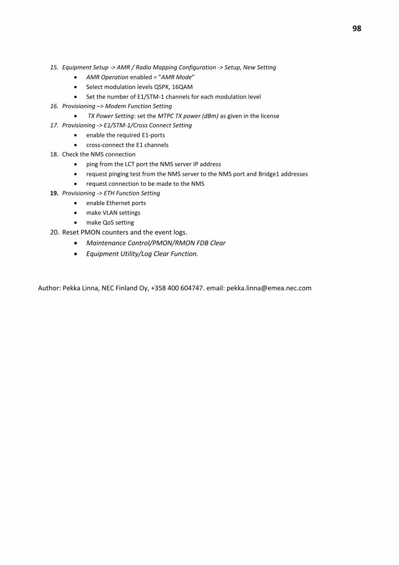
98
15. Equipment Setup -> AMR / Radio Mapping Configuration -> Setup, New Setting
AMR Operation enabled = ”AMR Mode”
Select modulation levels QSPK, 16QAM
Set the number of E1/STM-1 channels for each modulation level
16. Provisioning –> Modem Function Setting
TX Power Setting: set the MTPC TX power (dBm) as given in the license
17. Provisioning -> E1/STM-1/Cross Connect Setting
enable the required E1-ports
cross-connect the E1 channels
18. Check the NMS connection
ping from the LCT port the NMS server IP address
request pinging test from the NMS server to the NMS port and Bridge1 addresses
request connection to be made to the NMS
19. Provisioning -> ETH Function Setting
enable Ethernet ports
make VLAN settings
make QoS setting
20. Reset PMON counters and the event logs.
Maintenance Control/PMON/RMON FDB Clear
Equipment Utility/Log Clear Function.
Author: Pekka Linna, NEC Finland Oy, +358 400 604747. email: [email protected]