CostruireInLegno Inglese DEF - Free University of Bozen...
17
Timber buildings low-energy constructions Cristina Benedetti Carlo Dal Vera Mariangela Gavioli Davide Gigli Maurita Glorioso Cristina Pasquale Simona Pezzucchi Elia Terzi
Transcript of CostruireInLegno Inglese DEF - Free University of Bozen...

Timber buildingslow-energy constructions
Cristina BenedettiCarlo Dal VeraMariangela GavioliDavide GigliMaurita GloriosoCristina PasqualeSimona PezzucchiElia Terzi

Title of the original Italian edition:Costruire in legno - edifici a basso consumo energetico, 2a edizione riveduta e ampliata
Content development:Cristina Benedetti editorCarlo Dal Vera and Cristina Pasquale building details planningMaurita Glorioso 3D models planningMariangela Gavioli climate zones and materialsDavide Gigli building physics and hygrothermal performanceSimona Pezzucchi acoustics and living comfortElia Terzi timber construction methods
Translation: Ada Anastasia Brant Special thanks to Norbert Hofer and Lukas Hofer for their support.Very special thanks to Chris Stieda for his splendid work and his great help in editing the English translation, as well as to Stefano Pasquale for his expertise and his commitment and to the UBC students Adam Robertson and Maik Gehloff.
Graphic design:Mater|generative design - www.studiomater.comEmanuele Pangrazi concept design and digital illustrationsChiara Poli graphic design and layout
Printed in June 2010 by Tipolitografia Visconti, Terni (IT)
Distribution:Universitätsbibliothek BozenBiblioteca Universitaria di BolzanoUniversity Library of Bozen-Bolzano
Bozen-Bolzano University Press
Universitätsplatz 1 / Piazza Università 1I - 39100 Bozen/BolzanoT: +39 0471 012 300F: +39 0471 012 309www.unibz.it/[email protected]
© 2010 Bozen - Bolzano University PressBozen/BolzanoProprietà letteraria riservata
All rights reserved. No part of this publication may be reproduced or transmitted in any form or by any means, electronically or mechanically, including photocopying, recording or any information storage or retrieval system, without prior permission in writing from the publisher.
ISBN 978-88-6046-033-2
Kindly supported by:

Contents Foreword 005
Construction project and hygrothermal performance 008 Introduction 008 Material properties 010 Properties of a layer composition 011 Hygrothermal performance of building elements 012 · Geoclimatic conditions 012 · Physical-technical specifications 012 · Determination of layer sequence 012 · Thermal analysis for winter conditions 016 · Hygrothermal performance 018 · Condensation buildup 018 · Thermal analysis under summer conditions 020
Material analysis related to climate zone 022
Table of symbols 026
Construction details 1 · Foundation-to-wall connection 027 2 · Overhang 045 3 · Interior wall 061 4 · Exterior wall 077 5 · Green roof 093 6 · Flat roof 105 7 · Pitched roof - eaves 119 8 · Pitched roof - ridge 135
Indoor well-being 151 Health and well-being 152 Indoor air quality 152 Toxic substances and their sources 154 Monitoring and control systems 155 Wood and indoor air quality 158 Soundproofing 159 Acoustic transmission 160 Timber construction and acoustics 162 A few planning aids 163
Wood and wood composites 165
Bibliography 171


005
A new language is increasingly making its way into the European architectural landscape, a language sensitive to environmental and energy issues and open to the use of new and different materials. The use of wood, a building material with great symbolic and emotional value that has influenced entire epochs and cultures throughout time, plays an important role in this architectural movement. In many European countries, building with timber is seen as an effective measure to counteract the greenhouse effect. The use of timber in public and private construction projects is stimulated through aid and development programs. Nevertheless, more wood grows than is used. In order to maintain the natural balance of the forest it is necessary to plan timber logging and usage. In Italy, the wide acceptance of residential construction in wood is hampered by cultural reservations about building with timber. Wood buildings are often associated with mountain chalets, provisional shelters, or traditional rural structures. Furthermore, the durability of wood is questioned,
Cristina Benedetti
maintenance issues are overblown, or allegations of poor fire performance are made. Meanwhile, the excellent fire resistance of timber is forgotten. Often, shortcomings can be traced back to insufficient planning or faulty execution: planners frequently lack the necessary education, advanced training, or up-to-date information.It is therefore not only necessary to develop efficient and innovative systems of timber construction, but also to provide technically and aesthetically convincing examples. The basis for this lies in the hands of experienced, educated, and informed planners and craftsmen.
Timber frame constructionIn the first decade of the 19th century, parallel to the “conquest” of North America from Chicago to the Pacific Coast, the grand work was laid for the revolutionary changes in house construction that took place in the second half of the 20th century. Unimpeded by local traditions, standardization of cross-sectional dimensions was
readily accepted leading to economics in the manufacture of timber construction. Both were revolutionary because by using wood new floor plans and manufacturing systems for housing could be developed, which permitted simple, flexible and economical house construction. The use of timber fit right into the dynamic society and economy of the North American continent at the time. It was not a short-lived trend, but instead continues to have a significant and widespread impact today. Each activity and every undertaking called for fast action. On one hand, the reasons for this were objective, such as the settlement of new areas and the erection of new buildings but they were also psychologically rooted in the atmosphere of change and spirit for adventure that dominated at the time. At the same time, machines were developed to manufacture nails industrially. This caused the price of nails to drop significantly, making them a mass product whose circulation was pushed onward by pioneers on their long march west. This unique interplay of social, economic, and technological
ForewordTimber buildings · low-energy constructions
Foreword

006
conditions led to the creation and development of the on-site balloon and platform-frame systems, which later resulted in the first industrialized construction methods in the building sector. All utilized components are standardized, inexpensive, and enable short construction times: even unspecialized workers can erect the support structure of a medium-sized home in about four days under the supervision of a foreman. Over the course of time, research turned towards the development of technical solutions for four- and five-story buildings. Up until that time, timber construction had been limited to single family homes and row houses because of the limited building height. In 1996, the EU program “Cost action E5” examined these questions, analyzing and also solving problems of various natures: acoustic and thermal insulation, structural calculations and methods of representation, fire performance, and seismic stability. All these aspects were experimentally tested with the six-story Timber Frame 2000 building constructed in Great Britain.
Cross-laminated solid timber boards (X-lam)In Europe, these new construction methods – with K. Wachsmann’s “General Panel System” as a leading example – led the way to
prefabricated systems that are “open” and flexible as well as easily combinable with other systems and materials. This evolution manifested itself in profound changes to structural conceptualization and architectural language. Beyond this, the industries manufacturing the timber support structures clearly oriented themselves towards the production of elements with high, tested mechanical properties. The necessity of saving energy and resources in construction has contributed to reducing the use of energy in the construction process, diminishing waste of materials, increasing the use of renewable energies and building materials, and the recent development of a new construction system in which large panels assume a supporting function. This building method has a large number of followers in timber construction in Austria, Germany, and the Italian regions South Tyrol and Veneto. The high prefabrication level of elements and the extremely short building construction times optimize the process. Means of transportation is the only factor limiting the size of the building elements. The panels are made up of – thanks to finger jointing – large format elements that are, depending on the production method, multilayered and cross-laminated with each other. The size and strength of the individual sections (including
the wall and floor sections), the assembly of the individual cross-laminated layers, the joining details, positioning and thickness of insulation, and the types of wood used all depend on the patents of the different manufacturers, the static parameters, and last but not least, on the desired architectural result.
Concluding notesThe growing number of companies dedicated to research in this field, and the use of wood by renowned architects – from Thomas Herzog to Tadao Ando – are leading to a renaissance of this raw material. New construction methods using solid wood open up new possibilities of form and expression: elaborately detailed architecture utilizing a wide variety of materials that emphasize energy efficiency and environmental sustainability can now be built. Above all, the growing attention to possibilities of saving energy has bred new methods of design. Architectural decisions have since been closely tied to the use of renewable resources, which also influence aesthetic considerations. Wood as a building material has reemerged in the building world as a technical innovation. Technical developments and quality control go hand in hand: building components prefabricated in-factory guarantee a reliable system
Foreword Timber buildings · low-energy constructions

007
and the quality of individual components. On-site labor input is kept low, computer numerical control (CNC) machines enable complex and exact processing, a high level of precision in the fabrication of joints, and the completion of components that until recently were still technically unthinkable and/or far too expensive. Industry has been able to solve a great many of the problems regarding fire performance, durability, and maintenance that once limited the use of wood for buildings. However, there are other aspects, such as seismic stability, that need more in-depth testing before they can meet Italian standards. It is now the task of instructors at all centers of learning to counteract the lack of information and knowledge about the qualities of wood, to fully enable the unfolding of its technological and architectural potential.
This book arose in this context, and its contents are based upon the experiences of the CasaClima Masters Program at the Free University of Bozen Bolzano. In cooperation with the CNR-IVALSA (Institute for Wood and Tree Species Research, located in San Michele all’Adige, led by Prof. A. Ceccotti) and during the course of the SOFIE 1 Project, several “students” – the coauthors of this book – collaborated on the planning of a new guesthouse for the
institute. The same panels that were employed for the structure in Miki for earthquake safety tests were used here. The drawings in the chapter sections “From project… to realization” show a few of the details of the project and the corresponding thermal analyses. This publication therefore also represents a “handbook” for the planning and realizing of projects using X-lam elements.
1 SOFIE stands for Sistema cOstruttivo casa FIEmme, a research project funded by the autonomous Province of Trento on the development of a multistory structural system using cross-laminated layers of spruce that fulfills high mechanical requirements while maintaining low energy consumption. High standards for fire behavior, seismic safety, acoustic performance, and durability were also set. This construction is built solely using wood from the Trento province and costs are equivalent to conventional building methods.During testing, special attention was given to earthquake safety. The use of lightweight materials limits the effects of an earthquake. The specially designed supports can absorb high amounts of dynamic energy without the building being damaged. In addition to the many tests in Italy, two tests were also carried out in Japan: one on the shake table
of the NIED (National Institute for Earth Science and Disaster Prevention) in Tsukuba, the world’s most important institute for seismic research. During testing, a three-story building with the above-described supporting structure was subjected to three different types and magnitudes of earthquake simulations, one of which was equivalent to the 1995 earthquake in Kobe. The building endured all three simulations. Another test was carried out in October of 1997: a completely new type of experiment in which a seven-story building with this support structure was subjected to an earthquake simulation on the world’s largest shake table in Miki, Kobe. This experiment was completed with equal success.
SOFIESistema cOstruttivo casa FIEmme
ForewordTimber buildings · low-energy constructions

Construction project and hygrothermalperformance
008 Construction project and hygrothermal performance
Introduction
Every built structure continuously endeavorsto create a balance between indoor andoutdoor climate conditions:
· thermal behavior of the structure in response to indoor and outdoor temperatures and to the divergence between summer and winter conditions;· hygrometric performance of the building in response to indoor-outdoor and summer winter humidity fluctuations.
The impact of seasonal conditions is dependant upon the climate at the building location, i.e. latitude, longitude.
Available information generally corresponds to specific materials. In order to thoroughly understand the behavior of a construction element as a whole, in-depth, step-bystep testing and analysis must be carried out prior to undertaking the final planning process.
The results presented here are not to be understood as absolute, but instead as a means of understanding the relative ratios of the different values and what they mean for planning: the same materials will always deliver different total values, similar layer compositions on the other hand, will always provide comparable values.
No. MATERIAL d r m λ R sd Tgr (°C)
Psat (Pa)
Pd(Pa)
c f0
Material table
LAYE
R N
UMBE
R
MA
TERI
AL
DESC
RIPT
ION
TEM
PERA
TURE
PRO
GES
SIO
N
LAYE
R TR
AN
SITIO
N V
APO
R PR
ESSU
RE
SATU
RATE
D VA
POR
PRES
SURE
A B E D
TEST ELEMENT
Total thickness (cm)
Total area-related mass (kg/m2)
Total thermal resistance (m2K/W)
Total thermal transmission coefficient (W/m2K)
Phase shift (h)
Thermal wave amplitude attenuation (%)
Cross-section description
A
B
C
D
Timber buildings · low-energy constructions

009Construction project and hygrothermal performance
Supplemental information
SINGLE MATERIAL TOTAL LAYER BUILDUP OF MATERIALS
A · Geometric properties
Thickness d (cm): thickness in centimeters d (cm): thickness in centimeters
B · Physical properties
Density r (kg/m3): weight of one cubic meter of material
Area-related mass m (kg/m2): weight of one square meter of layer buildup m=r•d
Heat conductivity l (W/mK): heat conductivity of the material
Thermal resistance R (m2K/W): resistance of the material to heat flow influx R=d/l
C · Thermal properties (winter)
Thermal resistance resistance of the layer buildup to heat fluxRtot = Rsi + S Ri + Rse
Thermal transmittance coefficient U (W/m2K): rate of heat flow through the layer buildup U=1/Rtot
D · Thermal properties (summer)
Specific heat capacity c (J/kgK): the amount of heat stored per temperature change
Modified Fourier number f0(-): capacity of the material to absorb temperature fluctuations
Phase shift j (h): the length of time it takes a thermal wave to pass through the layer buildup
Thermal wave amplitude attenuation TAV (%): attenuation of the temperature wave by the layer buildup
E · Hygrometric performance
μ (-): vapor diffusion resistance factor
sd (m): diffusion-equivalent air layer thickness sd=μ•d
n
i=1
Timber buildings · low-energy constructions
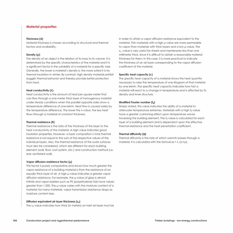
Material properties
Thickness (d)Material thickness is chosen according to structural and thermal factors and availability.
Density (ρ)The density of an object is the relation of its mass to its volume. It is determined by the specific characteristics of the material and it is a significant factor in the suitability of a material for a specific task. Generally, the lower a material’s density is, the more suited it is for thermal insulation in winter. By contrast, high density materials exhibit sluggish thermal behavior and thereby provide better protection from heat.
Heat conductivity (λ)Heat conductivity is the amount of heat per square meter that can flow through a one-meter thick layer of homogenous material under steady conditions when the parallel opposite sides show a temperature difference of one kelvin. Heat flow is caused solely by the temperature difference. The lower the λ-value, the less heat flows through a material of constant thickness.
Thermal resistance (R)Thermal resistance is the ratio of the thickness of the layer to the heat conductivity of the material. A high value indicates good insulation properties. However, a layer composition’s total thermal resistance is not equal to the sum of the respective values of the individual layers. Also, the thermal resistance of the outer surfaces must also be considered, which are different for each building element (wall, floor, roof system, etc.) and construction method (i.e. rear ventilated wall).
Vapor diffusion resistance factor (μ)This factor is purely comparative and shows how much greater the vapor resistance of a building material is than the resistance of an equally thick layer of air. A high μ-value indicates a greater vapor diffusion resistance. For example, the μ-value of glass is almost infinite and vapor barriers such as PE (polyethylene) foils have values greater than 1,000. The μ-value varies with the moisture content of a material; for many materials, vapor transmission resistance drops as moisture content rises.
Diffusion equivalent air layer thickness (sd)The sd-value indicates how thick (in meters) an inert air layer must be
in order to attain a vapor diffusion resistance equivalent to thematerial. Thin materials with a high μ-value are more permeable to vapor than materials with thick layers and a low μ-value. The sd -value is very useful for sheets and membranes less than one millimeter thick, since it is difficult to obtain a reasonable material thickness for them. In this case, it is more practical to indicate the thickness of an air layer corresponding to the vapor diffusion coefficient of the material.
Specific heat capacity (c)The specific heat capacity of a material shows the heat quantity necessary to raise the temperature of one kilogram of that materialby one kelvin. The specific heat capacity indicates how fast a material will react to a change in temperature and is affected by its density and inner structure.
Modified Fourier number (f0)Simply stated, this value indicates the ability of a material to attenuate temperature extremes. Materials with a high f0-value have a greater cushioning effect upon temperature waves traversing the building element. The f0-value is calculated for each layer of a building element and is dependant upon the effective thermal resistance and the heat penetration coefficient.
Thermal diffusivity (α) Thermal diffusivity is the rate at which warmth passes through a material. It is calculated with the formula α = λ /(c•ρ).
010 Construction project and hygrothermal performance Timber buildings · low-energy constructions

011
Properties of a layer composition
Total thickness (d)In a low-energy home, certain structural elements, whether it be the walls, floors, or roof, can become quite thick due to the high demand for thermal insulation.
Area-related mass (m)The area-related mass is the weight of one square meter of a construction element’s area. It is equal to the sum of the masses ofthe individual layers.Standardization norms dictate minimum values for the area-related mass. Beyond this, there is no general rule, as the ideal value depends upon location, climate conditions, and the building’s intended use.
Thermal transmittance coefficient (U)The thermal transmittance coefficient or total heat exchange value is a measure of the heat flux through a layer composition when theprevailing temperatures on each side are divergent.This value specifies the amount of energy that flows through one-square-meter area in one second when the inert air temperatures on each side differ by one kelvin.The total thermal transmittance coefficient (U) is reciprocal to the total thermal resistance (R) of a layer construction and is normally used to indicate how well a material insulates. In Italy, minimum values for architectural elements based upon the climate zone in which the building is erected are listed in the legislative ordinance 192/2005 and subsequent amendments.
* In Italy KlimaHaus® - CasaClima (in english ClimateHouse) is a well-known
standard for low-energy buildings, with restrictive values and evaluations.
Diffusion-equivalent air layer thickness (sd)The sum of the sd-values for each material component of a layer composition equals its total sd-values. The lower the value, the less resistance to vapor pressure the layer has. However, a good
hygrometric performance is defined less by absolute sd-values and more by the correct sequence of the individual layers.
Phase shift (j)Phase shift indicates the span of time a temperature wave needs to move from the exterior to the interior of a building element. Theoretically, a phase shift of twelve hours is ideal, since excess heat can then be dispersed during the cooler night hours. At a phase shift of over 24 hours, the interior temperature tends to reach equilibrium, since very little heat radiates back out.
Thermal wave amplitude attenuation (TAV)Amplitude attenuation is the ratio of the exterior temperature spectrum to that of the interior. The greater the phase shift, the smaller the temperature fluctuations are.
Construction project and hygrothermal performance
VALUE (W/m2K) EVALUATION
U > 0.75 Poor •
0.75 > U > 0.25 Average • •
0.25 > U > 0.15 ClimateHouse standard * • • •
U < 0.15 Passive House • • • •
VALUE of each material (m) EVALUATION
sd < 0.1 breathable membrane
sd > 1 vapor retarder
sd > 100 vapor barrier
sd > 1000 waterproof membrane
VALUE (h) EVALUATION
j < 8 Poor •
8 < j < 12 Average • •
12 < j < 24 Good • • •
j > 24 Very good • • • •
VALUE (%) FLUCTUATION
TAV > 10 High •
10 > TAV > 1 Average • •
1 > TAV > 0.1 Low • • •
TAV < 0.1 Imperceptible • • • •
Timber buildings · low-energy constructions

Hygrothermal performance of building elements
1· Geoclimatic conditionsIt is not possible to wholly understand the results of hygrothermal performance tests and analyses without seeing them within their specific geographic and climatic context.An exact description of the environment is very important. Not all planning software available on the market permits viewing of their database; often only fragmentary data are available, or they use outdated or unimplemented standards for calculation. This means that it is absolutely necessary to know how the data on geoclimatic conditions were compiled and required to supplement missing information.
INPUT:geoclimatic conditions of the site area· average monthly temperature and relative humidity· average winter temperature lows· climate zone· heating degree days· altitude
OUTPUT:element performance efficiency and code specification requirements
Monthly averages and average winter temperature lows for all Italian provincial capitals are listed in the UNI Norms. Heating degree days, climate zones, and altitude must be defined for each municipality. Officially determined values should be deliberately used with the aim of eliminating possible sources of error or misunderstanding. As far as possible, indisputable and official geoclimatic data should be used for calculations. However, if more recent data are available (provided by meteorological stations, for example), it can lead to more exact results. If such data are used, they must have been gathered across a time period of at least 15 years. The data source should be named.
2· Physical-technical specificationsWhenever building material manufacturers provide certifications by independently accredited testing institutions they should be used as the calculation basis, since they contain more realistic values. Planners and builders have the right to insist upon such certification. In the case of a grievance due to discrepancies between calculated results and actual performance, the planner can maintain indemnity by proving use of certified values. If no
certified values are available, UNI Standards data, which includes statistics about the general properties of various materials, should be used.
3· Determination of layer sequenceThe sequence of the individual layers has no influence on the thermal transmittance coefficient, but does affect both hygrothermal performance and the performance of the structural element during summer. An incorrect layer sequence will cause errors in the evaluation of the structural element.It is important to take notice of the “direction” in which the planning program computes, from indoors to outdoors or the other way around. All software packages allow the user to select the building element to be calculated, i.e. wall, ceiling, or roof. Element type affects how thermal radiance impacts the exterior of each layer composition and therefore also the thermal exchange (Rsi or Rse) occurring at that point, which can vary for each structural component.As mentioned previously, it is fundamental that the layers are in correct sequential order. This is made visible by the following example:
A brief analysis of transmittance, phase shift, and amplitude attenuation shows how the order of the layers influences the overall performance of the entire building element.
(See table on opposite page.)
012 Construction project and hygrothermal performance
Thickness
(d)
Density
(r)
Heat conductivity
(λ)
Specific heat capacity
(c)
X-lam timber 14.2 cm 500 kg/m3 0.130 W/mK 1600 J/kgK
Stone wool 8 cm 55 kg/m3 0.040 W/mK 1030 J/kgK
Timber buildings · low-energy constructions
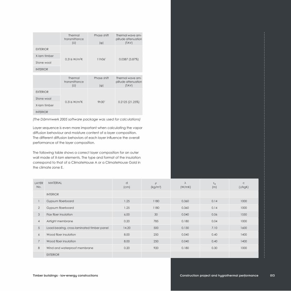
Layer sequence is even more important when calculating the vapor diffusion behaviour and moisture content of a layer composition. The different diffusion behaviors of each layer influence the overall performance of the layer composition.
The following table shows a correct layer composition for an outer wall made of X-lam elements. The type and format of the insulation correspond to that of a ClimateHouse A or a ClimateHouse Gold in the climate zone E.
013
(The Dämmwerk 2005 software package was used for calculations)
Construction project and hygrothermal performance
Thermaltransmittance
(U)
Phase shift
(φ)
Thermal wave am-plitude attenuation
(TAV)
EXTERIOR
0.316 W/m2K 11h06’ 0.0387 (3.87%)X-lam timber
Stone wool
INTERIOR
LAYER No.
MATERIAL d(cm)
r(kg/m3)
λ (W/mK)
sd(m)
c(J/kgK)
INTERIOR
1 Gypsum fiberboard 1.25 1180 0.360 0.14 1000
2 Gypsum fiberboard 1.25 1180 0.360 0.14 1000
3 Flax fiber insulation 6,00 30 0.040 0.06 1550
4 Airtight membrane 0.20 785 0.180 0.04 1000
5 Load-bearing, cross-laminated timber panel 14.20 500 0.130 7.10 1600
6 Wood fiber insulation 8.00 250 0.040 0.40 1400
7 Wood fiber insulation 8.00 250 0.040 0.40 1400
8 Wind and waterproof membrane 0.20 920 0.180 0.30 1000
EXTERIOR
Timber buildings · low-energy constructions
Thermaltransmittance
(U)
Phase shift
(φ)
Thermal wave am-plitude attenuation
(TAV)
EXTERIOR
0.316 W/m2K 9h30’ 0.2125 (21.25%)Stone wool
X-lam timber
INTERIOR

Two aspects must be given particular attention. The program has already converted the µ-value into the sd-value. This is done with the simple equation sd = µ•d. It would be advantageous to express material thickness in meters. Since centimeters are generally used for architectural and structural planning, it is important to keep this in mind.From a structural point of view, the construction is still incomplete: the wood studs that will bear the interior gypsum fiberboard are missing, as is the exterior insulation. The construction is therefore non-homogeneous.
An non-homogeneous layer composition is one that is not definable with a single list of layer sequence.
A brick wall with a single layer of insulation is a homogenous layer composition; a wall with wooden studs and plates distributed across the entire length with fasteners for the cladding is non-homogeneous.In order to describe the system as a whole, one must divide it into cross-sections that can be analyzed individually.The non-homogeneous sector must also be examined and incorporated as a percentage of the overall structure in order to obtain a weighted total transmittance value for the layer composition.
In practice, thermal transmittance coefficients are calculated using two cross-sections. After the width and stud spacing have been determined for the non-homogeneous cross-section, the percentage of the total center-to-center distance each cross-section represents can be calculated, in order to arrive at a final value for the overall thermal transmission coefficient that takes both cross-sections proportionally into consideration.
In the following table, non-homogeneous cross-sections are highlighted in bold and cursive: for example, the flax fiber insulation is interrupted at regular intervals by wooden studs.
014 Construction project and hygrothermal performance
LAYER No.
MATERIAL d(cm)
r(kg/m3)
λ (W/mK)
sd(m)
c(J/kgK)
INTERIOR
1 Gypsum fiberboard 1.25 1180 0.360 0.14 1000
2 Gypsum fiberboard 1.25 1180 0.360 0.14 1000
3 Flax fiber insulation 6.00 30 0.040 0.06 1550
Wood battens 6.00 400 0.110 4.00 2500
4 Airtight membrane 0.20 785 0.180 0.04 1000
5 Load-bearing, cross-laminated timber panel 14.20 500 0.130 7.10 1600
6 Wood fiber insulation 8.00 250 0.040 0.40 1400
Wood battens 8.00 400 0.110 4.00 2500
7 Wood fiber insulation 8.00 250 0.040 0.40 1400
Orthogonal battens 8.00 400 0.110 4.00 2500
8 Wind and watertight membrane 0.20 920 0.180 0.30 1000
EXTERIOR
Timber buildings · low-energy constructions
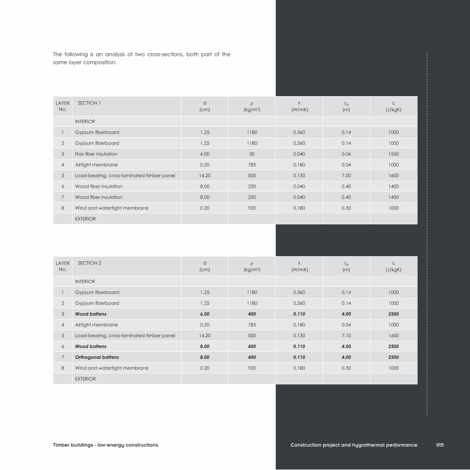
The following is an analysis of two cross-sections, both part of the same layer composition:
015Construction project and hygrothermal performance
LAYER No.
SECTION 1 d(cm)
r(kg/m3)
λ (W/mK)
sd(m)
c(J/kgK)
INTERIOR
1 Gypsum fiberboard 1.25 1180 0.360 0.14 1000
2 Gypsum fiberboard 1.25 1180 0.360 0.14 1000
3 Flax fiber insulation 6.00 30 0.040 0.06 1550
4 Airtight membrane 0.20 785 0.180 0.04 1000
5 Load-bearing, cross-laminated timber panel 14.20 500 0.130 7.00 1600
6 Wood fiber insulation 8.00 250 0.040 0.40 1400
7 Wood fiber insulation 8.00 250 0.040 0.40 1400
8 Wind and watertight membrane 0.20 920 0.180 0.30 1000
EXTERIOR
LAYER No.
SECTION 2 d(cm)
r(kg/m3)
λ (W/mK)
sd(m)
c(J/kgK)
INTERIOR
1 Gypsum fiberboard 1.25 1180 0.360 0.14 1000
2 Gypsum fiberboard 1.25 1180 0.360 0.14 1000
3 Wood battens 6,00 400 0.110 4.00 2500
4 Airtight membrane 0.20 785 0.180 0.04 1000
5 Load-bearing, cross-laminated timber panel 14.20 500 0.130 7.10 1600
6 Wood battens 8.00 400 0.110 4.00 2500
7 Orthogonal battens 8.00 400 0.110 4.00 2500
8 Wind and watertight membrane 0.20 920 0.180 0.30 1000
EXTERIOR
Timber buildings · low-energy constructions

Calculation of thermal transmission coefficient (U) for non-homogeneous sections
In order to understand the calculation of proportion as a percentage, it is first necessary to take a look at layers 1 to 3:
For the sake of simplicity, we will look at one square meter of the surface. That gives us (0.17 + 0.60 + 0.17) • 1 m2 of insulation and (0.03 + 0.03) • 1 m2 of wood battens, or 94% of the cross-section containing insulation as compared to only 6% containing wood battens. The U-value of the non-homogeneous layer composition is a weighted average of the values of both cross-sections.
Caution: this example is only a simplification of a much more complex calculation process and cannot be implemented as a simplified approach to such calculations. The basis of calculations must always be the applicable standards or the software package used for planning.
The more levels of unhomogeneity a layer composition has, the more difficult and less exact the calculations become. Above all, unhomogeneity in different directions has proven to be particularly difficult to evaluate with much precision. Vertical studs in a horizontal cross-section are easy to calculate, as are horizontal plates in a vertical cross-section. However, when a combination of vertical and horizontal heterogeneity occurs within a single building element, calculations become very complex.For this reason, this book lists each and every material of a layer composition, even when it is heterogeneous. However, previously revised and averaged values are listed in the summary tables showing the general characteristics of a building element. Therefore, discrepancies between these values and those listed in the layer tables can occur. As can be seen, the example results listed here and those calculated by individual planners can, for various reasons, diverge. As initially mentioned, final results depend upon the method of calculation and other secondary factors.The numbers listed here are not to be seen as absolute or unequivocal: order of magnitude is more important than one single value. It is also important to reflect on means of attaining certain properties and, finally, to construct each element in such a way that the assumed properties can be achieved as closely as possible.
The individual steps described below must not be seen in isolation, despite the sequential order required for the book, but seen instead as part of a coherent planning process.
016
Double gypsum fiberboard
Insulation Wood studs Insulation Wood studs Insulation
17 cm 3 cm 60 cm 3 cm 17 cm
4· Thermal analysis for winter conditionsThermal analysis for winter conditions is simple. As soon as the layer sequence has been determined, the following values must be ascertained for each material:
· Thickness· Density· Area-related mass· Thermal conductivity· Thermal resistance· Heat transmittance coefficient.
These values are sufficient to determine the thermal efficiency of the building based upon the physical properties of the materials. In order to determine if the building is suited for specific climatic conditions, a precise location must be entered into the calculations.
Construction project and hygrothermal performance Timber buildings · low-energy constructions

Idealized diagram
[A]
[B]
[C1]
[C2]
Gradient diagram
Isotherm diagram
017
TEMPERATURE PROGRESSION
[A] The thickness of each layer is drawn to scale. The temperature progression within the layer composition is visible. An indoor temperature of 20 °C and an outdoor temperature of -10 °C was assumed for planning purposes.
[B] A temperature of 12 °C is assumed for the unheated side of internal building elements (party walls or load-bearing inner walls). The external surface of underground building elements is calculated with 4 °C, since this temperature can be assumed to prevail throughout the winter at a depth of one meter.
[C] Compared to the isotherm diagram [C2], the gradient diagram [C1] of temperature distribution is easier to read and facilitates the identification of thermal bridges.
[Graph]Observing the distribution of temperature within a layer composition permits control over the possible accumulation of condensation. Graphic representations make it easy to discern interstitial condensation points and/or places where a building element doesn’t “act right”. Temperature should decrease uniformly from indoors to out.
Layers (from outside to inside)
-10 °C
20 °C
Construction project and hygrothermal performanceTimber buildings · low-energy constructions