
Acme oasis acme group kandivali_archstones property solutions_asps_bhavik_bhatt


ContentsStar-Line® Series Overview ........................................................................ 1
Star-Line EX® Series Overview................................................................... 2
Star-LokTM Series Overview ........................................................................ 3
Environmental Highlights, Double Lead Acme Thread Features,Wire Limitation Guide ................................................................................. 4
Contact Insert Features-Mod I, Mod II, Mod III ..................................... 5 - 6
Connector Component Ordering Details ............................................. 7 - 11
Plug Hardware Assemblies ................................................................ 12 - 15
Receptacle Hardware Assemblies ..................................................... 16 - 21
EX Hardware ...................................................................................... 22 - 25
Insert Configuration Listing with Electrical Ratings& Spare/Replacement Contacts ........................................................ 26 - 30
Insert Configurations ......................................................................... 31 - 59
Connector Components, Spare Parts and Accessories .................... 60 - 67
Conduit System Accessories ............................................................. 68 - 69
Crimping, Insertion and Removal Tools ............................................. 70 - 71
Single Pole Power Connectors .......................................................... 72 - 73
Other Amphenol®/Pyle® Connectors ................................................. 74 - 75
Sales Offices and Distributors Listing ....................................................... 76

AmphenolINDUSTRIAL
STAR-LINE® SeriesStar-Line Series “ZP/ZR” connectors are heavy duty environmentally sealed plugs and receptacles and havebeen successfully used in all types of Industrial and Aerospace applications. These compact environmentalconnectors have provided outstanding performance in complex ground support cable networks, automatic andprocess control systems and instrumentation systems.
This family of connectors has made a major contribution to the successful interconnection of peak powergenerating systems as well as offshore petroleum production for power distribution and data acquisition.
Ample margins of safety and reliability have been designed into the Star-Line connectors to maintaincapability levels which make them ideally suited for the broad spectrum of demands placed on them byindustry.
The specific materials and design features incorporated in Star-Line connectors were originally selected tosatisfy the stringent requirements of the Aerospace industry for heavy-duty connectors. These connectorscombine electrical and mechanical capabilities that equal or exceed the performance parameters establishedby the Military Specification MIL-C-5015.
• CIRCUIT BREAKING – U/L & CSA listed power types have been thoroughly tested for capability to rupturecurrent at ratings listed*.
• ENVIRONMENTAL RESISTANCE – Design and materials withstand the most challenging operating conditions.Series has an IP 67 rating.
• SOLDER, CRIMP AND PRESSURE TERMINALS – Available in circuit-breaking power and control typesas listed.
• EASILY ACCESSIBLE WIRE TERMINALS – Conductors are readily terminated to contacts. Cable housings areslipped over conductors or leads after terminating. Cumbersome handling and seating of inserts with conductorsattached is eliminated.
• LARGE WIRING SPACE – Amplewiring space is provided in cablehousings and conduit fitting bodies.Hub of body mounts in any of fourpositions (except FS & FD boxassemblies).
• REVERSIBLE INSERTS – A fullrange of contact inserts andapplication adapters are available.All are interchangeable andreversible to suit special needs.
• DOUBLE-LEAD THREADCOUPLING – Modified AcmeThread does not clog underadverse conditions of ice, snow,sand or mud and provides the quickcoupling feature.
• HARD ANODIC COATING – Allmachine, aluminum parts finishedto 40 Points on Rockwell C Scale.Dielectric strength 1800 volts. Heatresistance of 750° F.
• HIGH TENSILE STRENGTH*ALUMINUM – Bar StockComponents precision machined.Points of impact designed forextra strength.
1
*This connector series is currently being reviewed to change over to UL 1682 from the present UL 1977 specification.

The Star-Line EX Series is ahybrid form of the parentStarline product line. Theseries is certified for use in
a Zone 1-IIc hazardousenvironment. Classified facilities such aspetrochemical refineries, land and offshoredrilling systems are but a few of the applicationsfor this broad product series.
• CENELEC CERTIFIED – for Zone 1-IIchazardous environment. Certificate numberEx97D1143X (file number 51A4467).
Listed under EEx d IIc T6.
• HARD ANODIC COATING – All machinedaluminum parts finished to 40 Points on theRockwell C Scale. Dielectric strength 1800volts. Heat resistance of 750° F.
• SOLDER, CRIMP AND PRESSURETERMINALS – Available in circuit breakingpower and control types.
• REVERSIBLE INSERTS – A full range ofcontact inserts for power, signal and mixedapplications are available. All areinterchangeable and reversible tosuit specific needs.
• EASILY ACCESSIBLE WIRE TERMINALS – Conductors are readily terminated to contacts. Cablehousings are slipped over conductors or leads after terminating. Cumbersome handling and seatingof inserts with conductors attached is eliminated.
• LARGE WIRING SPACE – Ample wiring space is provided in cable housings and hardware.
• HIGH TENSILE STRENGTH ALUMINUM – Bar Stock Components precision machined. Points of impactdesigned for extra strength.
• CABLE OPTIONS – Starline EX Series can be terminated onto unarmored or armored and sheathedcables built to IEEE-45 / UL1309, IEC, BS, DIN and JIC standards. Flexible cables like SOOW-A, W, G-GCand DLO constructions can also be used with this Series.
• INSERT VARIETY – A broad range of inserts are offered ranging from single-contact to 143 contacts.High amperage up to 1135 amps at 1000V / AC or DC. Contacts are high quality copper with silver plating.(Gold plating available as an option) Composite inserts for power, control and instrumentation serviceare available.
2
STAR-LINE® EX Series

AmphenolINDUSTRIAL
3
The Star-Lok’s unique swiftmate spring-loadedreverse bayonette coupling mechanism, createsa positive metal to metal lock-up between the plugand receptacle, with a simple push of the plug tomate and a simple eighth turn and pull to unmate.
• CIRCUIT BREAKING – U/L & CSA listed powertypes thoroughly tested for capability to rupturecurrent at ratings listed.*
• ENVIRONMENTAL RESISTANCE – Design andmaterials withstand the most challengingoperating conditions. Series has an IP 67 rating.
• HARD ANODIC COATING – AII machine, aluminumparts finished to 40 Points on Rockwell C Scale.Dielectric strength 1800 volts. Heat resistance of750° F.
• SOLDER, CRIMP AND PRESSURE TERMINALSAvailable in circuit breaking power andcontrol types.
• REVERSIBLE INSERTS – A full range of contactinserts for power, signal and mixed applicationsare available. All are interchangeable andreversible to suit specific needs.
• EASILY ACCESSIBLE WIRE TERMINALS –Conductors are readily terminated to contacts.Cable housings are slipped over conductors orleads after terminating. Cumbersome handlingand seating of inserts with conductors attached is eliminated.
• LARGE WIRING SPACE – Ample wiring space is provided in cable housings and hardware.
• HIGH TENSILE STRENGTH ALUMINUM – Bar Stock Components precision machined. Points of impactdesigned for extra strength.
Star-Lok’s new innovative design features a patented coupling mechanism – a one-handed swift engagementprovides a positive connection and consistent mating.
Star-Lok’s coupling mechanism also eliminates the problems associated with threaded coupling (dirt, threaddamage, many turns to fully mate, etc.), ensuring positive mating every time. The mechanism requires only aslight turn and pull to unmate and is engineered to resist vibration.
Star-Lok’s resistance to axial wear offers true metal-to-metal bottoming of mated components. Star-Lok isdeveloped from the proven Pyle Star-Line connector platform and offers: a large family of inserts, contactsand hardware options and an array of signal, power and mixed arrangement designs.
STAR-LOKTM Series
*This connector series is currently being reviewed to change over to UL 1682 fromthe present UL 1977 specification.

4
EnvironmentalHighlights
The double-lead Acme thread is a moderate torque quick-coupling thread which permits complete coupling inapproximately one turn of the coupling nut. In addition,there are actually two parallel threads having startingpoints 180 degrees apart. All of this ensures that plugsand receptacles are being mated or unmated axially.The thread contour makes it self-cleaning.
STAR-LINE® Family Series
MIL-C-5015REQUIREMENTSCLASSES A, B, E STAR-LINE, STAR-LOK
PROPERTY J & R CONNECTORS
TEMPERATURE -67° F to 225° F Temperature Classes A, B, E,J and R can withstand 257° Fcontinuously. For short durationhigh-temperature life,consult factory.
PRESSURE No requirement 300 PSI external(coupled connectors)200 PSI internal(with pin and socket inserts)
AIR LEAKAGE 1 cubic inch/ Exceeds Classes Ehour maximum and R specifications
HUMIDITY AND 1 1/2 times A.C. Exceeds ClassesMOISTURE voltage rating after E and R.RESISTANCE 14 days. MIL-C-5015
Exposure to Meets MIL-STD-202B,95% relative Method 106Ahumidity at 160° F.
CORROSIION 48 Hours – Salt spray: 300 daysRESISTANCE Method 1001 – No exposure of base metal.
MIL-STD-1344No exposure ofbase metal.
CHEMICAL No requirement Oil, most acidsRESISTANCE and alkalis.
DUST No requirement Meets MIL-STD-202B,RESISTANCE Method 110, Condition B
SHOCK 50 G minimum Exceeds 60 G’sRESISTANCE Certain inserts available
to 200 G.
VIBRATION Method 2006 Exceeds Method II &Method II MIL-STD-167-1 (Ships).MIL-STD-1344
TEST PROBE Contact size Exceeds MIL-C-5015ABUSE No. 16 and No. 18 on all contacts
No. 18 through 4/0.
Why the Double-LeadAcme Thread?
There are restrictions to the maximum diameter of wireas they relate to the rear or wire side of the connectorinsert as follows.
Mod I. When wires are passed through the rigid backinsulation for ease of soldering:
Wire size Maximum diameter#4/0 .747”#2/0 .555”#4 .400”#8 .262”#10 .201”#12 .150”#16 .107”#18 .086”
Mod II & III#10 .248”#12 .193”#16 .130”#18 .110”
Wire LimitationGuide
Standard double-lead One parallel thread removedAcme. Two parallel threads. to show actual thread angle.

AmphenolINDUSTRIAL
MOD II insulations have one less rigid disc than theirMOD I counterparts.
Individual unmounted contacts are crimped to theirrespective wires outside of the connector where ampleworking space is available. The crimping operation can beby hand or power operated tool.
Contacts with crimped joint intact are inserted one by one,with a hand tool, into the insulation premounted within theconnector barrel shell.
The resilient portion of the insert functions to seal aroundthe contacts and prevent leakage through contactcavities, seal against leakage between the insert andshell, absorb
The combined “sandwich” provides all the advantages ofresilient mounting plus all the advantages of rigid mounting,with none of the shortcomings of either. Under pressure,between a shoulder and a thrust washer, the silicone reacts asa fluid and being non-compressible, flows against all surfacesto affect a reliable seal around the periphery of the insert andaround all contacts where they penetrate the insulation.
Contact cavities are clearly numbered on the front and rearinsert face to facilitate identification during assembly,inspection and maintenance. Socket insulator contact cavitiesare of a bellmouth guided entry design. These chamfered lead-ins insure easy and positive mating of male contacts.
Self-sealing Construction: all MOD I captive contactinserts are capable of being terminated after assembly inthe basic barrel and are completely self-sealing whenpressurized by any selected adapter. Water, gas, vapor,moisture or dust positively cannot pass in either directionthrough or around the insulation.
The “sandwich” construction of MOD I inserts consists of aresilient silicone laminate between two rigid plastic insulators.The resilient laminate seals absorbs shock and vibrationand allows the contacts to align themselves freely. The rigidfaced plastic insulators impart just the right amount ofrestraint to retain the contacts in place.
shock and vibration, provide electrical insulation betweencontacts and retain the contacts in the connector.
Contacts may be inserted and removed without degradationof the retention or environmental capability. The front rigidportion of the insert functions to stabilize and ensure positivealignment of the contacts.
Contact cavities are clearly numbered on the front andrear insert face to facilitate identification duringassembling, inspection and maintenance. Socket insulatorcontact cavities are of a bellmouth guided entry design.These chamfered lead-ins ensure easy and positivemating of male contacts.
5
STAR-LINE® Family Series
AdapterWasher
PressurePad
Red
MOD I Captive Contact InsertsDouble Lead Acme Thread
Shell Seal
Adapter Seal
Cable Adapter
Coupling Nut
Rigid Rear Insulator
Receptacle Shell
PressurePad
Plug Shell Rigid Front Insulator
Resilient Contact Seal Laminant
MOD II Insertable/Removable Crimp Contact Inserts
Double Lead Acme Thread
Shell Seal
Adapter SealAdapter Washer
Pressurizing Sleeve
Cable Adapter
Coupling Nut
Resilient InsulatorReceptacle Barrel
Contact Seal
Plug Barrel
Rigid Insulator
Green
PressurizingSleeve
Insert Seal

MOD III Insertable/Removeable Crimp Collet
Retained Contact
SummaryThe foregoing is a brief explanation of the three basic insert designs offered within this catalog. It offers differentand distinct advantages for the cable terminator, electrician and production worker.
When the connector is in use, as a functional device the insert MOD design has no effect on the intermateability of theconnector. When a configuration you have selected gives you a choice of MOD design, ask yourself the followingquestions:
1. Do you have a large quantity of connectors to apply? If you do, then the crimp removable series would beappropriate with its inherent timesaving advantages during terminations.
2. Are circuits likely to be changed often, i.e., would the connector function as a “patching device?” Here, too, thecrimp versions with easily removed and installed contacts are advantageous.If a contact configuration is desired but is not shown, consult the factory. Insert arrangements are constantly beingadded to the line.
Three element contact inserts are factory installed andlocked into position with a non-removable retaining ring.This “sandwich” assembled insert, for rear-insertable andreleased contacts consist of a resilient laminant sealinterposed between two rigid plastic insulators. Thisproven design concept eliminates the potential failurepossibilities normally found in all resilient or all rigidinserts by combining all the advantages of both theresilient and rigid mounting systems.
The resilient laminant insulator absorbs shock or vibrationand allows contacts to adjust themselves freely. Theresilient insulator affects a full and reliable seal aroundeach contact when compressed by seating of theaccessory hardware. In addition, the laminant alsoprovides a seal between the connector insert and theinternal bore of the plug or receptacle shell.
The rigid rear insulator supports and locks theberyllium copper collets. The rigid front insulatorpositions the forward contact-locating shoulder and thecollet tines lock the rear shoulder of the contacts. Thecontacts are positively restrained against forward andrear movement. The main advantages of colletretention are lower insertion forces, eliminating needfor insertion tools, and higher retention forces. Colletlocking tines permit the contacts to be released andremoved from the rear of the insert for quick and easycircuit changes.
Contact cavities are clearly numbered on the front andrear insert face to facilitate identification duringassembly, inspection and maintenance. Socketinsulator contact cavities are of a bellmouth guidedentry design. These chamfered lead-ins ensure easyand positive mating of male contacts.
6
STAR-LINE® Family Series
ShellSeal Insert
RetainingRing
Cable Adapter
Coupling Nut
Adapter Seal
Plug Barrel
Collet
InsertRetainingRing
Receptacle Barrel
Rigid Front Insulator
Resilient Contact Seal LaminantDouble Lead Acme Thread
Rigid Rear Insulator

AmphenolINDUSTRIAL
Ordering InformationAll plug and receptacle assemblies require two part numbers:A. The catalog number of the desired insert.B. The catalog number of the selected plug or receptacle hardware.
To Order Complete Assemblies1. Determine supply voltage, amperage and number of contacts desired.
2. Select insert configuration from pages 31-59. Write down Dash Number, Shell Size and MOD number ofinsert. Voltage and amperage information can be found on page 27. Example: 3#12 contacts – 27P (MALE)and 27S (FEMALE); MOD I; Shell Size 12 (page 32).
3. Select desired plug and receptacle hardware from pages 9-25. Make certain that the shell size of thehardware corresponds with the shell size of the desired insert. Determine outside diameter of cable. Example:Male Plug with Basket Weave. Cable is 3 conductor #12 (.635 outside diameter). ZPLK-1212-27P (page 15).
Female Receptacle mounted to Junction Box with 45° Angle Adapter and 1” Conduit Hub. ZRLBB-312-27S(page 21).
4. Order tools from pages 70-71.
Power Connectors – 20-30-60-100-200-325-700 Amperes, 1 thru 10 Contacts
Control & Instrumentation Connectors – 3 thru 143 Contacts
The following pages present connector sub-assemblies which are available and can be used in conjunction with theinserts listed.
Custom BuildYour Own Connectors
To Order Assemblies Without The Insert(For large users stocking connector components in bulk)
1. If a MOD I insert will be used, order the hardware by the catalog number and eliminate theasterisk. Example: ZPLD-1212 (page 12).
2. If a MOD II insert will be used, order by the catalog number but substitute a 200 for theasterisk. Example: ZPLD-1212-200
3. MOD III inserts must be ordered assembled in their basic barrel (consult factory).
PIN INSERTCONFIGURATION
PLUGCONFIGURATION
RECEPTACLECONFIGURATION
SOCKET INSERTCONFIGURATION
7
STAR-LINE® Family Series

Connector Assemblies
1. Hardware with a longer cable housing should be used ifthe insert has:
A. Any pressure contact – line or ground.B. More than 10 contacts-any size.C. More than 4 #10 or larger contacts.
2. A jack coupling nut should be used if the insert has:A. A configuration with shorter relay contacts.B. A configuration of 37 or more contacts.
A JACK COUPLING NUT SHOULD NOT BE USED ONANY POWER INSERT CONNECTOR THAT IS TO BEDISCONNECTED UNDER LOAD
Shell Size Torque Setting (lb. ft.)12 11,016 13.520 15.5
C20 15.524 23.0
C24 23.028 31.0
C28 31.0
NOTE: The N.E.C. circuit breaking and non-circuit breakingratings are based on test results of contacts and connectors.Consult the N.E.C. when selecting wire/cable for specificapplications. Under certain conditions, a wire size may be ratedhigher or lower than our table indicates for a given contact size.
Please Read Carefully:
ENVIRONMENTALCOVER – FEMALE
SQUARE FLANGE RECEP-TACLE
FLANGEGASKET
SOCKETCONTACTS
INSERTCLAMP
NUT
MECHANICALCLAMP NUT
WASHER
GROMMET
CABLE ADAPTER
MALE INSERT
PIN CONTACTS
COUPLINGNUT
MALE SKIRT
ENVIRONMENTALCOVER – MALE
Typical MOD I Plug Components
Typical MOD I Receptacle Components
3. To insure proper coupling the following torque valuesshould be used on the coupling nut:
8
STAR-LINE® Family Series
FEMALE INSERT

AmphenolINDUSTRIAL
ConnectorBasic Components
Square FlangeReceptacle Straight Plug
In-Line Receptacle
Typical Assemblies
9
STAR-LINE®
Square FlangeMounted Plug

Code LogicStar-Line & Star-Lok Series
Kellems(Basket weave grip) /
M forMechanicalnut clamp /
D forgland nut
332-Z P E K L J- 18 20- P N K -01
ProductSeriesPrefix
Z– Star-LineS – Star-Lok
P for Plug /R for cablemounted
Receptable(Inline)
Environmental Cover/
L for no cover
Long cableadapter /Blank forstandard
length
Jack nut(37 conductors
or more /Do not use for
“C” powerapplications /100 amp or
greater)
Grommetcode number(cable dia.)
Shell sizeof connector
(physical size)/C before
shell numberfor 100 amp.
& higher
Insert pattern(32 for solder /
332 forMod 2 crimp /
632 forMod 3 crimp)
P for Pin(male) /
S for socket(female)
N for crimpcontact /
R for pres-sure /
Blank forsolder
K for goldplated
contact /Blank forstandard
OptionalAlternate
KeyPosition
Cable Mounted Connectors
P forpanel mount /
BB forback box
(see pg. 18)
Z R E P- 20- 332- S N K -01
R forreceptacle /P for plug
Environmental Cover/
L forno cover /
C forflip cover
Insert pattern(32 for solder /
332 forMod 2 crimp /
632 forMod 3 crimp)
Fixed Connectors
S forsocket
(female) /P for pin(male)
N forcrimp
contact /R for pressure /
Blank forsolder
K forgold platedcontact /Blank forstandard
10
OptionalAlternate
Key Position
STAR-LINE® • STAR-LOKTM
ProductSeriesPrefix
Z– Star-LineS – Star-Lok
Shell sizeof connector

AmphenolINDUSTRIAL
Star-Lok connectors are an industrial gradeenvironmental family of swiftmating plugs andreceptacles for power, signal and mixed applications. These environmental connectors provide outstandingperformance in complex automation, process controland many varied industrial systems.
Ample margins of safety and reliability have been designed into the Star-Lokconnectors to maintain capability levels which make them ideally suited for anextensive spectrum of industry demands. The specific materials and designfeatures incorporated into Star-Lok connectors were originally selected tosatisfy the stringent requirements of the Aerospace industry for heavy-dutyconnectors. These connectors combine electrical and mechanicalcapabilities that exceed the performance parameters established bythe Military Specification MIL-C-5015.
ConnectorBasic Components
11
STAR-LOKTM

Size Shell Cat. No. DIMENSIONS Catalog No.Cable Size With Standard WITH STANDARD CABLE ADAPTER With Jack
Coupling Nut A B C Coupling Nut
12 _PLD-▲-12-* 5-3/8 1-13/16 5-31/32 ZPLDJ-▲-12-*16 _PLD-▲-16-* 5-5/8 2-5/16 5-7/32 ZPLDJ-▲-16-*20 _PLD-▲-20-* 6-1/8 2-13/16 6-23/32 ZPLDJ-▲-20-*
C20 _PLD-▲-C20-* 6-5/8 2-13/16 7-7/32 ZPLDJ-▲-C20-*24 _PLD-▲-24-* 6-5/8 3-5/16 7-7/32 ZPLDJ-▲-24-*
Select C24 _PLD-▲-C24-* 7-1/8 3-5/16 7-23/32 ZPLDJ-▲-C24-*from 28 ZPLD-▲-28-* 7-1/8 3-13/16 7-23/32 ZPLDJ-▲-28-*
Table Below C28 ZPLD-▲-C28-* 7-5/8 3-13/16 8-7/32 ZPLDJ-▲-C28-*
andSubstitute 12 _PLDL-▲-12-* 7-5/8 1-13/16 8-7/32 ZPLDLJ-▲-12-*Symbol No. 16 _PLDL-▲-16-* 7-7/8 2-5/16 8-15/32 ZPLDLJ-▲-16-*for Delta▲ 20 _PLDL-▲-20-* 8-3/8 2-13/16 8-31/32 ZPLDLJ-▲-20-*
C20 _PLDL-▲-C20-* 8-7/8 2-13/16 9-15/32 ZPLDLJ-▲-C20-*24 _PLDL-▲-24-* 8-7/8 3-5/16 9-15/32 ZPLDLJ-▲-24-*
C24 _PLDL-▲-C24-* 9-3/8 3-5/16 9-31/32 ZPLDLJ-▲-C24-*28 ZPLDL-▲-28-* 9-1/8 3-13/16 9-23/32 ZPLDLJ-▲-28-*
C28 ZPLDL-▲-C28-* 9-5/8 3-13/16 10-7/32 ZPLDLJ-▲-C28-*
Straight PlugWith Standard Compression Nut
To specify plug with environmental cover,change third letter in Part No. “L’ to “E’.Example: _PLD changes to _PED.
Shell Shell Shells Shells Shells Shell Shell Shell Shells ShellsCable Dia. 12 16 20 & C20 24 & C24 28 & C28 Cable Dia. 12 16 20 & C20 24 & C24 28 & C28
.062 to .125 02 – – – – 1.500 to 1.625 – – 26 26 26
.125 to .250 04 – – – – 1.625 to 1.750 – – 28 28 28
.250 to .375 06 06 – – – 1.750 to 1.875 – – 30 30 30
.375 to .500 08 08 – – – 1.875 to 1.937 – – 31 – –
.500 to .625 10 10 10 – – 1.937 to 2.000 – – – 32 32
.625 to .750 12 12 12 – – 2.000 to 2.125 – – – 34 34
.750 to .875 14 14 14 – – 2.125 to 2.250 – – – 36 36
.875 to .937 15 – – – – 2.250 to 2.375 – – – 38 38
.937 to 1.000 – 16 16 16 – 2.375 to 2.437 – – – 39 –1.000 to 1.125 – 18 18 18 – 2.437 to 2.500 – – – – 40
1.125 to 1.250 – 20 20 20 – 2.500 to 2.625 – – – – 421.250 to 1.375 – 22 22 22 – 2.625 to 2.750 – – – – 441.375 to 1.437 – 23 – – – 2.750 to 2.875 – – – – 461.437 to 1.500 – – 24 24 24
OIL-RESISTANT RUBBER GROMMETS—SYMBOL NUMBERS OF SIZES AVAILABLE Substitute the symbol number for the Delta ▲in the catalog number of plug. Example: _PLD-▲ -12-* for .500 to .625 Dia. Cable changes to _PLD-10 12-*
To specify a complete plug, substitute the Dash No. of the contact insert selected, for the Asterisk (*) in the Catalog No. below .NOTE: The jack nut should not be used with current rupture insert configurations.
WITH LONG CABLE ADAPTER
For Star-Line series add a “Z” to the beginning of catalog no. (Ex. ZPLD).For Star-Lok series add an “S” to the beginning of catalog no. (Ex. SPLD).
Types_PLD _PED
12
STAR-LINE® • STAR-LOKTM

AmphenolINDUSTRIAL
13
Size Shell Cat. No. DIMENSIONS Catalog No.Cable Size With Standard WITH STANDARD CABLE ADAPTER With Jack
Coupling Nut A B C D E Coupling Nut
12 _PLM-▲-12-* 6-1/8 1-13/16 6-23/32 2-3/8 1-3/4 ZPLMJ-▲-12-*16 _PLM-▲-16-* 6-7/16 2-5/16 7-1/32 3 2-1/4 ZPLMJ-▲-16-*20 _PLM-▲-20-* 7 2-13/16 7-19/32 3-3/4 2-3/4 ZPLMJ-▲-20-*
C20 _PLM-▲-C20-* 7-1/2 2-13/16 8-3/32 3-3/4 2-3/4 ZPLMJ-▲-C20-*24 _PLM-▲-24-* 7-9/16 3-5/16 8-5/32 4-1/2 3-1/4 ZPLMJ-▲-24-*
Select C24 _PLM-▲-C24-* 8-1/16 3-5/16 8-21/32 4-1/2 3-1/4 ZPLMJ-▲-C24-*from 28 ZPLM-▲-28-* 8-1/8 3-13/16 8-23/32 5-1/8 3-3/4 ZPLMJ-▲-28-*
Table Below C28 ZPLM-▲-C28-* 8-5/8 3-13/16 9-7/32 5-1/8 3-3/4 ZPLMJ-▲-C28-*
andSubstitute 12 _PLML-▲-12-* 8-3/8 1-13/16 8-31/32 2-3/8 1-3/4 ZPLMLJ-▲-12-*Symbol No. 16 _PLML-▲-16-* 8-11/16 2-5/16 9-9/32 3 2-1/4 ZPLMLJ-▲-16-*for Delta▲ 20 _PLML-▲-20-* 9-1/4 2-13/16 9-27/32 3-3/4 2-3/4 ZPLMLJ-▲-20-*
C20 _PLML-▲-C20-* 9-3/4 2-13/16 10-11/32 3-3/4 2-3/4 ZPLMLJ-▲-C20-*24 _PLML-▲-24-* 9-13/16 3-5/16 10-13/32 4-1/2 3-1/4 ZPLMLJ-▲-24-*
C24 _PLML-▲-C24-* 10-5/16 3-5/16 10-29/32 4-1/2 3-1/4 ZPLMLJ-▲-C24-*28 ZPLML-▲-28-* 10-1/8 3-13/16 10-23/32 5-1/8 3-3/4 ZPLMLJ-▲-28-*
C28 ZPLML-▲-C28-* 10-5/8 3-13/16 11-7/32 5-1/8 3-3/4 ZPLMLJ-▲-C28-*
Straight PlugWith Mechanical Clamp Nut
To specify plug with environmental cover,change third letter in Part No. “L’ to “E’.Example: _PLM changes to _PEM.
Shell Shell Shells Shells Shells Shell Shell Shell Shells ShellsCable Dia. 12 16 20 & C20 24 & C24 28 & C28 Cable Dia. 12 16 20 & C20 24 & C24 28 & C28
.062 to .125 02 – – – – 1.500 to 1.625 – – 26 26 26
.125 to .250 04 – – – – 1.625 to 1.750 – – 28 28 28
.250 to .375 06 06 – – – 1.750 to 1.875 – – 30 30 30
.375 to .500 08 08 – – – 1.875 to 1.937 – – 31 – –
.500 to .625 10 10 10 – – 1.875 to 2.000 – – – 32 32
.625 to .750 12 12 12 – – 2.000 to 2.125 – – – 34 34
.750 to .875 14 14 14 – – 2.125 to 2.250 – – – 36 36
.875 to .937 15 – – – – 2.250 to 2.375 – – – 38 38
.875 to 1.000 – 16 16 16 – 2.375 to 2.437 – – – 39 –1.000 to 1.125 – 18 18 18 – 2.375 to 2.500 – – – – 40
1.125 to 1.250 – 20 20 20 – 2.500 to 2.625 – – – – 421.250 to 1.375 – 22 22 22 – 2.625 to 2.750 – – – – 441.375 to 1.437 – 23 – – – 2.750 to 2.875 – – – – 461.375 to 1.500 – – 24 24 24
OIL-RESISTANT RUBBER GROMMETS—SYMBOL NUMBERS OF SIZES AVAILABLE Substitute the symbol number for the Delta ▲in the catalog number of plug. Example: _PLM-▲ -12-* for .500 to .625 Dia. Cable changes to _PLM-10 12-*
To specify a complete plug, substitute the Dash No. of the contact insert selected, for the Asterisk (*) in the Catalog No. below.NOTE: The jack nut should not be used with current rupture insert configurations.
WITH LONG CABLE ADAPTER
For Star-Line series add a “Z” to the beginning of catalog no. (Ex. ZPLD).For Star-Lok series add an “S” to the beginning of catalog no. (Ex. SPLD).
Types_PLM _PEM
STAR-LINE® • STAR-LOKTM

Straight PlugWith Conduit Adapter (for flexible conduit fittings)To specify a complete plug, substitute the dash no. of the contact insert selected for the asterisk (*)in the catalog no. below. NOTE: The jack nut should not be used with current rupture insert configurations.A PLUG WITH JACK COUPLING NUT SHOULD BE USED WITH INSERTS HAVING 37 OR MORE CONTACTS
Shell Open Catalog No. DIMENSIONS Catalog No.Size Back With Standard With Jack
Coupling Nut A B C G H J Coupling Nut12 ZPLP-12-* 2-3/8 1-13/16 2-31/32 1-17/64 1-5/8 3/16 ZPLPJ- 12-*16 ZPLP-16-* 2-13/32 2-5/16 3 1-11/16 2-1/8 7/32 ZPLPJ- 16-*20 ZPLP-20-* 2-7/16 2-13/16 3-1/32 2-3/32 2-5/8 9/32 ZPLPJ- 20-*C20 ZPLP-C20-* 2-15/16 2-13/16 3-17/32 2-3/32 2-5/8 9/32 ZPLPJ- C20-*24 ZPLP-24-* 2-15/32 3-5/16 3-1/16 2-17/32 3-1/8 11/32 ZPLPJ- 24-*C24 ZPLP-C24-* 2-31/32 3-5/16 3-9/16 2-17/32 3-1/8 11/32 ZPLPJ- C24-*28 ZPLP-28-* 2-15/32 3-13/16 3-1/16 3-1/32 3-3/4 11/32 ZPLPJ- 28-*C28 ZPLP-C28-* 2-31/32 3-13/16 3-9/16 3-1/32 3-3/4 11/32 ZPLPJ- C28-*
Use withor without
PottingSleeve
To specify plug with environmental cover,change third letter in Part No. “L” to “E”.Example: _PLT changes to _PET.
To specify a complete plug, substitute the dash no. of the contact insert selectedfor the asterisk (*) in the catalog no. below.NOTE The jack nut should not be used with current rupture insert configurationsA PLUG WITH JACK COUPLING NUT SHOULD BE USED WITH INSERTS HAVING 37 OR MORE CONTACTS
TypesZPLP ZPEP
To specify plug withenvironmental cover,change third letter inPart No. “L” to “E”.Example: ZPLPchanges to ZPEP.
Shell Size Catalog No. Catalog No.Size Conduit With Standard With Jack
Coupling Nut A B C D Coupling Nut12 3/4 _PLT-2 12-* 4-1/4 1-13/16 4-27-32 3/4 ZPLTJ-2 12-*16 1-1/4 _PLT-4 16-* 4-3/8 2-5/16 4-31/32 1-1/4 ZPLTJ-4 16-*20 1-1/2 _PLT-5 20-* 4-1/2 2-13/16 5-3/32 1-1/2 ZPLTJ-5 20-*C20 1-1/2 _PLT-5 C20-* 5 2-13/16 5-19/32 1-1/2 ZPLTJ-5 C20-*24 2 _PLT-6 24-* 4-5/8 3-5/16 5-7/32 2 ZPLTJ-6 24-*C24 2 _PLT-6 C24-* 5-1/8 3-5/16 5-23/32 2 ZPLTJ-6 C24-*28 2-1/2 ZPLT-7 28-* 5-3/32 3-13/16 5-11/16 2-1/2 ZPLTJ-7 28-*C28 2-1/2 ZPLT-7 C28-* 5-19/32 3-13/16 6-3/16 2-1/2 ZPLTJ-7 C28-*
J hole DIA.
DIMENSIONS
For Star-Line series add a “Z” to the beginning of catalog no. (Ex. ZPLT). For Star-Lok series add an “S” to the beginning of catalog no. (Ex. SPLT).
Types_PLT _PET
14
STAR-LINE® • STAR-LOKTM
Safety wire holes (3) .062 DIA
BH SQ.G SQ.A
Straight Male PlugPANEL MOUNT (Not available in Star-Lok)
C

AmphenolINDUSTRIAL
15
12 _PLKL-▲-12-* 7-5/8 1-13/16 8-7/32 ZPLKJ-▲-12-*16 _PLKL-▲-16-* 7-7/8 2-5/16 8-15/32 ZPLKJ-▲-16-*20 _PLKL-▲-20-* 8-3/8 2-13/16 8-31/32 ZPLKJ-▲-20-*C20 _PLKL-▲-C20-* 8-7/8 2-13/16 9-15/32 ZPLKJ-▲-C20-*24 _PLKL-▲-24-* 8-7/8 3-5/16 9-15/32 ZPLKJ-▲-24-*C24 _PLKL-▲-C24-* 9-3/8 3-5/16 9-31/32 ZPLKJ-▲-C24-*28 ZPLKL-▲-28-* 9-1/8 3-13/16 9-23/32 ZPLKJ-▲-28-*C28 ZPLKL-▲-C28-* 9-5/8 3-13/16 10-7/32 ZPLKJ-▲-C28-*
Straight PlugWITH BASKET WEAVE CABLE GRIP
To specify a complete plug, substitute the Dash No. of the contact insert selected for the asterisk (*) in the catalog no. below.NOTE: The jack nut should not be used with current rupture insert configurations.A PLUG WITH JACK COUPLING NUT SHOULD BE USED WITH INSERTS HAVING 37 OR MORE CONTACTS
Size Shell Catalog DIMENSIONS Catalog No.Cable No. With Standard WITH STANDARD CABLE ADAPTER With Jack
Size Coupling Nut A B C Coupling Nut12 _PLK-▲-12-* 5-3/8 1-13/16 5-31/32 ZPLKJ-▲-12-*16 _PLK-▲-16-* 5-5/8 2-5/16 6-7/32 ZPLKJ-▲-16-*20 _PLK-▲-20-* 6-1/8 2-13/16 6-23/32 ZPLKJ-▲-20-*C20 _PLK-▲-C20-* 6-5/8 2-13/16 7-7/32 ZPLKJ-▲-C20-*24 _PLK-▲-24-* 6-5/8 3-5/16 7-7/32 ZPLKJ-▲-24-*C24 _PLK-▲-C24-* 7-1/8 3-5/16 7-23/32 ZPLKJ-▲-C24-*28 ZPLK-▲-28-* 7-1/8 3-13/16 7-23/32 ZPLKJ-▲-28-*C28 ZPLK-▲-C28-* 7-5/8 3-13/16 8-7/32 ZPLKJ-▲-C28-*
To specify plug with environmental cover,change third letter in Part No. “L” to “E”.Example: _PLK changes to _PEK.
OIL-RESISTANT RUBBER GROMMETS—SYMBOL NUMBERS OF SIZES AVAILABLESubstitute the symbol number for the Delta s in the Catalog Number of Plug.Example: _PLK-▲-12-* for .500 to .625 Dia. Cable changes to _PLD-10 12-*
Shell Shell Shells Shells Shells Shell Shell Shell Shells ShellsCable Dia. 12 16 20 & C20 24 & C24 28 & C28 Cable Dia. 12 16 20 & C20 24 & C24 28 & C28
.062 to .125 02 – – – – 1.500 to 1.625 – – 26 26 26
.125 to .250 04 – – – – 1.625 to 1.750 – – 28 28 28
.250 to .375 06 06 – – – 1.750 to 1.875 – – 30 30 30
.375 to .500 08 08 – – – 1.875 to 1.937 – – 31 – –
.500 to .625 10 10 10 – – 1.875 to 2.000 – – – 32 32
.625 to .750 12 12 12 – – 2.000 to 2.125 – – – 34 34
.750 to .875 14 14 14 – – 2.125 to 2.250 – – – 36 36
.875 to .937 15 – – – – 2.250 to 2.375 – – – 38 38
.875 to 1.000 – 16 16 16 – 2.375 to 2.437 – – – 39 –1.000 to 1.125 – 18 18 18 – 2.437 to 2.500 – – – – 40
1.125 to 1.250 – 20 20 20 – 2.500 to 2.625 – – – – 421.250 to 1.375 – 22 22 22 – 2.625 to 2.750 – – – – 441.375 to 1.437 – 23 – – – 2.750 to 2.875 – – – – 461.375 to 1.500 – – 24 24 24
Selectfrom
Table Belowand
SubstituteSymbol No.for Delta ▲
WITH LONG CABLE ADAPTER
For Star-Line series add a “Z” to the beginning of catalog no. (Ex. ZPLK). For Star-Lok series add an “S” to the beginning of catalog no. (Ex. SPLK).
STAR-LINE® • STAR-LOKTM
Types_PLK _PEK

In-Line ReceptacleWith Mechanical Clamp Nut
OIL-RESISTANT RUBBER GROMMETS—SYMBOL NUMBERS OF SIZES AVAILABLESubstitute the symbol number for the Delta ▲ in the catalog number of plug.Example: ZRLM-▲-12-* for .500 to .625 Dia. cable changes to ZRLM-10 12-*
Shell Shell Shells Shells Shells Shell Shell Shell Shells Shells Cable Dia. 12 16 20 & C20 24 & C24 28 & C28 Cable Dia. 12 16 20 & C20 24 & C24 28 & C28
.062 to .125 02 – – – – 1.500 to 1.625 – – 26 26 26
.125 to .250 04 – – – – 1.625 to 1.750 – – 28 28 28
.250 to .375 06 06 – – – 1.750 to 1.875 – – 30 30 30
.375 to .500 08 08 – – – 1.875 to 1.937 – – 31 – –
.500 to .625 10 10 10 – – 1.875 to 2.000 – – – 32 32
.625 to .750 12 12 12 – – 2.000 to 2.125 – – – 34 34
.750 to .875 14 14 14 – – 2.125 to 2.250 – – – 36 36
.875 to .937 15 – – – – 2.250 to 2.375 – – – 38 38
.875 to 1.000 – 16 16 16 – 2.375 to 2.437 – – – 39 –1.000 to 1.125 – 18 18 18 – 2.437 to 2.500 – – – – 40
1.125 to 1.250 – 20 20 20 – 2.500 to 2.625 – – – – 421.250 to 1.375 – 22 22 22 – 2.625 to 2.750 – – – – 441.375 to 1.437 – 23 – – – 2.750 to 2.875 – – – – 461.375 to 1.500 – – 24 24 24
TypesZRLM ZREM
To specify a complete receptacle, substitute the Dash No. of the contact insert selected forthe Asterisk (*) in the Catalog below.
To specify receptacle with threadedenvironmental cover, change third letterin Part No. “L” to “E”.Example: ZRLM changes to ZREM.
16
STAR-LINE®
Size Shell Cat. No. DIMENSIONSCable Size With Standard
Coupling Nut A C D E F G
12 ZRLM-▲-12-* 6-1/8 6-3/4 1-3/4 1-61/64 1-3/4 2-3/816 ZRLM-▲-16-* 6-7/16 7-1/16 2-1/4 2-31/64 2-1/4 320 ZRLM-▲-20-* 7 7-5/8 2-3/4 3-1/32 2-3/4 3-3/4C20 ZRLM-▲-C20-* 7-1/2 8-1/8 2-3/4 3-1/32 2-3/4 3-3/424 ZRLM-▲-24-* 7-9/16 8-3/16 3-1/4 3-9/16 3-1/4 4-1/2C24 ZRLM-▲-C24-* 8-1/16 8-11/16 3-1/4 3-9/16 3-1/4 4-1/228 ZRLM-▲-28-* 8-1/8 8-3/4 3-3/4 4-1/16 3-3/4 5-1/8C28 ZRLM-▲-C28-* 8-5/8 9-1/4 3-3/4 4-1/16 3-3/4 5-1/8
WITH LONG CABLE ADAPTER12 ZRLML-▲-12-* 8-3/8 9 1-3/4 1-61/64 1-3/4 2-3/816 ZRLML-▲-16-* 8-11/16 9-5/16 2-1/4 2-31/64 2-1/4 320 ZRLML-▲-20-* 9-1/4 9-7/8 2-3/4 3-1/32 2-3/4 3-3/4C20 ZRLML-▲-C20-* 9-3/4 10-3/8 2-3/4 3-1/32 2-3/4 3-3/424 ZRLML-▲-24-* 9-13/16 10-7/16 3-1/4 3-9/16 3-1/4 4-1/2C24 ZRLML-▲-C24-* 10-5/16 10-15/16 3-1/4 3-9/16 3-1/4 4-1/228 ZRLML-▲-28-* 10-1/8 10-3/4 3-3/4 4-1/16 3-3/4 5-1/8C28 ZRLML-▲-C28-* 10-5/8 11-1/4 3-3/4 4-1/16 3-3/4 5-1/8
Selectfrom
Table Belowand
SubstituteSymbol No.for Delta ▲

AmphenolINDUSTRIAL
In-Line ReceptacleWith Standard Compression NutTo specify a complete receptacle, substitute the dash no. of the contact insert selected for the asterisk (*)
in the catalog no. below.
17
Size Shell Cat. No. DimensionsCable Size With Standard
Coupling Nut A C D E
12 ZRLD-▲- 12-* 5-3/8 6 1-3/4 1-61/6416 ZRLD-▲- 16-* 5-5/8 6-1/4 2-1/4 2-31/6420 ZRLD-▲- 20-* 6-1/8 6-3/4 2-3/4 3-1/32C20 ZRLD-▲- C20-* 6-5/8 7-1/4 2-3/4 3-1/3224 ZRLD-▲- 24-* 6-5/8 7-1/4 3-1/4 3-9/16C24 ZRLD-▲- C24-* 7-1/8 7-3/4 3-1/4 3-9/1628 ZRLD-▲- 28-* 7-1/8 7-3/4 3-3/4 4-1/16C28 ZRLD-▲- C28-* 7-5/8 8-1/4 3-3/4 4-1/16
12 ZRLDL-▲-12-* 7-5/8 8-1/4 1-3/4 1-61/6416 ZRLDL-▲-16-* 7-7/8 8-1/2 2-1/4 2-31/6420 ZRLDL-▲-20-* 8-3/8 9 2-3/4 3-1/32C20 ZRLDL-▲-C20-* 8-7/8 9-1/2 2-3/4 3-1/3224 ZRLDL-▲-24-* 8-7/8 9-1/2 3-1/4 3-9/16C24 ZRLDL-▲-C24-* 9-3/8 10 3-1/4 3-9/1628 ZRLDL-▲-28-* 9-1/8 9-3/4 3-3/4 4-1/16C28 ZRLDL-▲-C28-* 9-5/8 10-1/4 3-3/4 4-1/16
To specify receptacle with threadedenvironmental cover, change third letterin Part No. “L” to “E”.Example: ZRLD changes to ZRED.
OIL-RESISTANT RUBBER GROMMETS—SYMBOL NUMBERS OF SIZES AVAILABLESubstitute the symbol number Delta in the catalog number of plug.Example: ZRLD-▲-12-* for .500 to .625 Dia. Cable changes to ZRLD-10 12-*
Shell Shell Shells Shells Shells Shell Shell Shell Shells ShellsCable Dia. 12 16 20 & C20 24 & C24 28 & C28 Cable Dia. 12 16 20 & C20 24 & C24 28 & C28
.062 to .125 02 – – – – 1.500 to 1.625 – – 26 26 26
.125 to .250 04 – – – – 1.625 to 1.750 – – 28 28 28
.250 to .375 06 06 – – – 1.750 to 1.875 – – 30 30 30
.375 to .500 08 08 – – – 1.875 to 1.937 – – 31 – –
.500 to .625 10 10 10 – – 1.875 to 2.000 – – – 32 32
.625 to .750 12 12 12 – – 2.000 to 2.125 – – – 34 34
.750 to .875 14 14 14 – – 2.125 to 2.250 – – – 36 36
.875 to .937 15 – – – – 2.250 to 2.375 – – – 38 38
.875 to 1.000 – 16 16 16 – 2.375 to 2.437 – – – 39 –1.000 to 1.125 – 18 18 18 – 2.437 to 2.500 – – – – 40
1.125 to 1.250 – 20 20 20 – 2.500 to 2.625 – – – – 421.250 to 1.375 – 22 22 22 – 2.625 to 2.750 – – – – 441.375 to 1.437 – 23 – – – 2.750 to 2.875 – – – – 461.375 to 1.500 – – 24 24 24
Selectfrom
Table Belowand
SubstituteSymbol No.for Delta ▲
With Long Cable Adapter
STAR-LINE®
TypesZRLD ZRED

Dimensions Shell Size Size Conduit Cat. No. A B C D E
12 3/4 ZRLT-2 12-* 4-1/4 3/4 4-7/8 1-3/8 1-61/6416 1-1/4 ZRLT-4 16-* 4-3/8 1-1/4 5 2-1/4 2-15/3220 1-1/2 ZRLT-5 20-* 4-1/2 1-1/2 5-1/8 2-3/4 3-1/32C20 1-1/2 ZRLT-5 C20-* 5 1-1/2 5-5/8 2-3/4 3-1/3224 2 ZRLT-6 24-* 4-5/8 2 5-1/4 3-1/4 3-9/16C24 2 ZRLT-6 C24 5-1/8 2 5-3/4 3-1/4 3-9/1628 2-1/2 ZRLT-7 28-* 5-3/32 2-1/2 5-23-32 3-3/4 4-1/16C28 2-1/2 ZRLT-7 C28-* 5-19/32 2-1/2 6-7/32 3-3/4 4-1/16
In-Line ReceptacleWith Conduit Adapter(for flexible conduit fittings)
To specify a complete receptacle, substitute the Dash No. of thecontact insert selected, for the Asterisk (*) in the Catalog No. below.To specify receptacle with threaded environmental cover, change third letter in Part NO. “L” to “E””.
BNPT thread
Safety wire holes(3) .062 DIA.
TypesZRLT ZRET
To specify receptacle with threadedenvironmental cover, change third letterin Part No. “L” to “E”.Example: ZRLT changes to ZRET.
18
STAR-LINE®
A
D
E
C

AmphenolINDUSTRIAL
Square FlangeReceptacleTo specify a complete receptacle, substitute the Dash No. of the contact insert selected,for the Asterisk (*) in the Catalog No. below.
To specify receptacle with threadedenvironmental cover, change third letterin part number from “L” to “E”.Example: _RLP changes to _REP.
Threaded EnvironmentalCover with Sash Chain
Drill hole in panel 1/64" larger than Dimension “K” for front mounting or dimension “C” for back mounting**Maximum panel thickness may be increased 1/8" when using Standard Coupling Nut Plugs.
19
STAR-LINE® • STAR-LOKTM
Use
with
or
with
out
Pot
ting
Sle
eves
To specify receptacle with springdoor cover, change third letterin part number from “L” to “C”.Example: _RLP changes to _RCP.
Hinged Spring Door
DIMENSIONSShell Open WITH STANDARD CABLE ADAPTER Size Back Cat. No. A B C* E F G J K L N
12 _RLP- 12-* 1-3/4 1-3/8 1-1/2 11/64 2-15/16 2-1/8 1 1-11/32 2-15/16 2-1/816 _RLP- 16-* 2-1/4 1-11/16 2 13/64 2-15/16 2-1/8 1 1-27/32 2-21/64 1/420 _RLP- 20-* 2-3/4 2-3-32 2-1/2 7/32 2-15/16 2-3/16 1 2-11/32 2-21/64 1/4C20 _RLP- C20-* 2-3/4 2-3/32 2-1/2 7/32 2-7/16 2-11/16 1-1/2 2-11/32 2-53/64 3/424 _RLP- 24-* 3-1/4 2-17/32 3 9/32 2-15/16 2-3/16 1 2-27/32 2-21/64 1/4C24 _RLP- C24-* 3-1/4 2-17/32 3 9/32 2-7/16 2-11/16 1-1/2 2-27/32 2-53/64 3/428 ZRLP- 28-* 3-3/4 3-1/32 3-1/2 11/32 2-15/16 2-3/16 1 3-11/32 2-21/64 1/4C28 ZRLP- C28-* 3-3/4 3-1/32 3-1/2 11/32 2-7/16 2-11/16 1-1/2 3-11/32 2-53/64 3/4
For Star-Line series add a “Z” to the beginning of catalog no. (Ex. ZRLP).For Star-Lok series add an “S” to the beginning of catalog no. (Ex. SRLP).
Types_RLP _RCP _REP
EholeDia.
G
5/8

Size Hub DIMENSIONS Cable Size† Cat. No.
A B C D E F G H
3/4 _RLBB- 2 12-* 5-1/4 4-5/8 4-3/16 3-9/16 2-3/8 2-13/16 2-7/16 9/32
1 _RLBB-3 12-* 5-1/4 4-5/8 4-3/16 3-9/16 2-3/8 2-13/16 2-7/16 9/321 _RLBB-3 16-* 5-1/4 4-5/8 4-3/16 3-9/16 2-3/8 2-15/16 2-17/32 9/321-1/4 _RLBB-4 16-* 5-1/4 4-5/8 4-3/16 3-9/16 2-5/8 2-15/16 2-17/32 9/321-1/2 _RLBB-5 16-*1-1/4 _RLBB-4 20-* 6 5-1/4 4-1/2 3-7/8 3-3/4 3-39/64 3 9/321-1/2 _RLBB-5 20-* 6 5-1/4 4-1/2 3-7/8 3-3/4 3-39/64 3 9/322 _RLBB-6 20-* 6 5-1/4 4-1/2 3-7/8 3-3/4 3-39/64 3 9/321-1/4 _RLBB-4 C20-* 6 5-1/4 4-1/2 3-7/8 3-3/4 3-39/64 3-3/8 9/321-1/2 _RLBB-5 C20-* 6 5-1/4 4-1/2 3-7/8 3-3/4 3-39/64 3-3/8 9/322 _RLBB-6 C20-* 6 5-1/4 4-1/2 3-7/8 3-3/4 3-39/64 3-3/8 9/322-1/2 _RLBB-7 24-* 8 7 3-3/4 3-33/64 2-19/64 7/163 _RLBB-8 24-* 8 7 4-1/2 3-33/64 2-19/64 7/162-1/2 _RLBB-7 C24-* 8 7 3-3/4 3-33/64 2-21-32 7/163 _RLBB-8 C24-* 8 7 4-1/2 3-33-64 2-21-32 7/162-1/2 ZRLBB-7 28-* 8 7 3-3/4 3-1/2 2-7/64 7/163 ZRLBB-8 28-* 8 7 4-1/2 3-1/2 2-7/64 7/162-1/2 ZRLBB-7 C28-* 8 7 3-3/4 3-1/2 2-15/32 7/163 ZRLBB-8 C28-* 8 7 4-1/2 3-1/2 2-15/32 7/16
Receptacle Mountedto Junction BoxWith Angle AdapterTo specify a complete receptacle, substitute the Dash No. of the contact insert selectedfor the Asterisk (*) in the Catalog No. below.
† Other Hub Sizes also available.
SeeDrawingBelow
12
16
20
C20
24
C24
28
C28
To specify receptacle with spring doorcover, change third letter in part numberfrom “L” to “C”.Example _RLBB changes to _RCBB
To specify receptacle with threadedenvironmental cover, change third letterin part number from “L’ to “E”. Example:_RLBB changes to _REBB.
Hinged Spring Door Threaded EnvironmentalCover with Sash Chain
Types_RLBB _RCBB _REBB
For Star-Line series add a “Z” to the beginning of catalog no. (Ex. ZRLBB). For Star-Lok series add an “S” to the beginning of catalog no. (Ex. SRLBB).
20
STAR-LINE® • STAR-LOKTM
SHELL SIZES 12 - 16 - 20 - C20 SHELL SIZES 24 - C24 - 28 - C28

AmphenolINDUSTRIAL
Size Shell Cat. No. DIMENSIONSCable Size With Standard
Coupling Nut A B C D E F G H
3/4 _RLA- 2 12-* 5-1/4 4-5/8 4-3/16 3-9/16 2-3/8 1-27/32 1 9/321 _RLA-3 12-* 5-1/4 4-5/8 4-3/16 3-9/16 2-3/8 1-27/32 1 9/321 _RLA-3 16-* 5-1/4 4-5/8 4-3/16 3-9/16 2-3/8 1-27/32 1 9/321-1/4 _RLA-4 16-* 5-1/4 4-5/8 4-3/16 3-9/16 2-5/8 1/27/32 1 9/321-1/2 _RLA-5 16-* 5-1/4 4-5/8 4-3/16 3-9/16 2-5/8 1-27/32 1 9/321-1/4 _RLA-4 20-* 6 5-1/4 4-1/2 3-7/8 3-3/4 3-1/16 1-7/32 9/321-1/2 _RLA-5 20-* 6 5-1/4 4-1/2 3-7/8 3-3/4 2-1/16 1-7/32 9/322 _RLA-6 20-* 6 5-1/4 4-1/2 3-7/8 3-3/4 2-1/16 1-7/32 9/321-1/4 _RLA-4 C20-* 6 5-1/4 4-1/2 3-7/8 3-3/4 2-9/16 1-7/32 9/321-1/2 _RLA-5 C20-* 6 5-1/4 4-1/2 3-7/8 3-3/4 2-9/16 1-7/32 9/322 _RLA-6 C20-* 6 5-1/4 4-1/2 3-7/8 3-3/4 2-9/16 1-7/32 9/322-1/2 _RLA-7 24-* 8 7 3-3/4 2-11/32 1-1/2 7/163 _RLA-8 24-* 8 7 4-1/2 2-11/32 1-1/2 7/162-1/2 _RLA-7 C24-* 8 7 3-3/4 2-27/32 1-1/2 7/163 _RLA-8 C24-* 8 7 4-1/2 3-33-64 1-1/2 7/162-1/2 ZRLA-7 28-* 8 7 3-3/4 2-27/32 1-1/2 7/163 ZRLA-8 28-* 8 7 4-1/2 2-9/32 1-1/2 7/162-1/2 ZRLA-7 C28-* 8 7 3-3/4 2-25/32 1-1/2 7/163 ZRLA-8 C28-* 8 7 4-1/2 2-25/32 1-1/2 7/16
Receptacle Mountedto Junction BoxWith Straight AdapterTo specify a complete receptacle, substitute the Dash No. of the contact insertselected, for the Asterisk (*) in the Catalog No. below.
SeeDrawingBelow
12
16
20
C20
24
C24
28
C28
Hinged Spring Door Threaded EnvironmentalCover with Sash Chain
Types_RLA _RCA _REA
Other Hub Sizes also available.
To specify receptacle with spring doorcover change third letter in part numberfrom “L” to “C”.Example: _RLBB changes to _RCBB
To specify receptacle with threadedenvironmental cover change third letter in partnumber from “L’ to “E”. Example: _RLBBchanges to _REBB.
For Star-Line series add a “Z” to the beginning of catalog no. (Ex. ZRLA). For Star-Lok series add an “S” to the beginning of catalog no. (Ex. SRLA).
21
STAR-LINE® • STAR-LOKTM
SHELL SIZES 24 - C24 - 28 - C28SHELL SIZES 12 - 16 - 20 - C20

22
Code LogicStar-Line EX
EX 13 3
ProductSeriesPrefix
13 for MalePlug /15 for
FemaleInline/17 for
Femalepanel mount
“##” code for grommetsused w/ type “2” or “4”
hardware styles/“A,” “B” or “C” etc. forEEx d gland sizes
(see pg. 61)
Example: EX-13-3-C-20-332PNMale Plug with EEX gland for a cable with 0.95"/24.1mm O.D.,20ea #12/4.0mm male contacts
EX-15-4-1620-332SNFemale Inline with basket weave grip for a cable with 0.95"/24.1mm O.D.,20ea #12/4.0mm female contacts
EX-17-1-20-332SNFemale Panel Mount. 20ea #12/4.0mm female contacts.
EX-13-3-C-16-22PR-BSMale Plug with EEX gland for an armored cable with1.25"/31.75mm O.D. 4ea #4/25.0mm male contacts
EX-17-3-C-16-22SR-BSFemale Panel Mount with cable adapter withand EEX gland for an armored cable to match above.
STAR-LINE EX®
C
ConnectorShell Size
(12, 16, 20,24, 28, C20,C24, C28)
20 332 P N BS
InsertConfiguration
ContactGender
P forMale Pin /
S forFemale Socket
OptionalAlternate
KeyPositions
TerminationMethod
N for crimpcontact /
R for pressure /Blank for solder
ArmoredCable/Omit if
unarmored
-01
HardwareStyle
(see pgs.21, 22 & 23)

AmphenolINDUSTRIAL
Dimension A B C D E F GShell
12 8-3/4 (222.3) 1-3/4 (44.5) 1-1/2 (38.1) 2 (50.8) 15/16 (23.8) 2-3/8 (60.3) N/A
16 8-13/16 (223.8) 1-3/4 (44.5) 2 (50.8) 2-1/16 (52.4) 1-7/16 (36.5) 3 (76.2) N/A
20 8-7/8 (225.4) 1-3/4 (44.5) 2-1/2 (63.5) 2-1/8 (54.0) 1-15/16 (49.2) 3-3/4 (95.3) N/A
24 8-15/16 (227.0) 1-3/4 (44.5) 3 (76.2) 2-3/16 (55.6) 2-7/16 (61.9) 4-1/2 (114.3) N/A
28 9 (228.6) 3 1/16 (77.8) 4 3/16 (106.4) 2 1/4 ( 57.2) 2-7/8 (73.0) 5-1/8 (130.2) N/A
23
Amphenol
DIMENSION A B C D E F GSHELL
12 7-3/8 (187.3) 1-3/4 (44.5) 1-1/2 (38.1) 1-1/4 (31.8) 15/16 (23.8) 1-1/2 (38.1) 8 (203.2)
16 7-3/8 (187.3) 1-3/4 (44.5) 2 (50.8) 1-1/4 (31.8) 1-7/16 (36.5) 2 (50.8) 10-1/2 (266.7)
20 7-3/8 (187.3) 1-3/4 (44.5) 2-1/2 (63.5) 1-1/4 (31.8) 1-15/16 (49.2) 2-1/2 (63.5) 14-1/2 (368.3)
24 7-3/8 (187.3) 1-3/4 (44.5) 3 (76.2) 1-1/4 (31.8) 2-7/16 (61.9) 3 (76.2) 17-1/2 (444.5)
28 7-3/8 (187.3) 1-3/4 (44.5) 3-1/2 (88.9) 1-1/4 (31.8) 2-7/8 (73.0) 3-1/2 (88.9) 19 (482.6)
Dimension A B C* D** E F GShell
12 7-5/8 (193.7) 1-3/4 (44.5) 1-1/2 (38.1) N/A N/A N/A N/A
16 7-5/8 (193.7) 1-3/4 (44.5) 2 (50.8) N/A N/A N/A N/A
20 7-5/8 (193.7) 1-3/4 (44.5) 2-1/2 (63.5) N/A N/A N/A N/A
24 7-5/8 (193.7) 1-3/4 (44.5) 3 (76.2) N/A N/A N/A N/A
28 7-5/8 (193.7) 1-3/4 (44.5) 3-1/2 (88.9) N/A N/A N/A N/A
Plug with Kellems Grip
Plug with Mechanical Clamp
Plug with EEx d Gland
HardwareEX-13-2 Style
EX-13-3 Style
*Notes: For “C” length inserts, add 1/2" to both dimensions “A” & “B”.**Notes: For unarmored cable a Hawke 501/421 gland is furnished.
For armored and sheathed cables a Hawke 501/453 gland is furnished (detailed cable dimensions required)
EX-13-4 Style
Note: Dimensions “D” and “E” are controlled by the gland manufacturer, gland is included with the connector. POTTING IS NOT REQUIRED
INDUSTRIAL
STAR-LINE EX®

Dimension A B C D E F GShell
12 8-3/4 (222.3) 1-3/4 (44.5) 1-1/2 (38.1) 2 (50.8) 15/16 (23.8) 2-3/8 (60.3) N/A
16 8-13/16 (223.8) 1-3/4 (44.5) 2 (50.8) 2-1/16 (52.4) 1-7/16 (36.5) 3 (76.2) N/A
20 8-7/8 (225.4) 1-3/4 (44.5) 2-1/2 (63.5) 2-1/8 (54.0) 1-15/16 (49.2) 3-3/4 (95.3) N/A
24 8-15/16 (227.0) 1-3/4 (44.5) 3 (76.2) 2-3/16 (55.6) 2-7/16 (61.9) 4-1/2 (114.3) N/A
28 9 (228.6) 1-3/4 (44.5) 3-1/2 (88.9) 2-1/4 (57.2) 2-7/8 (73.0) 5-1/8 (130.2) N/A
Dimension A B C D* E F G
Shell
12 7-5/8 (193.7) 1-3/4 (44.5) 1-1/2 (38.1) N/A N/A N/A N/A
16 7-5/8 (193.7) 1-3/4 (44.5) 2 (50.8) N/A N/A N/A N/A
20 7-5/8 (193.7) 1-3/4 (44.5) 2-1/2 (63.5) N/A N/A N/A N/A
24 7-5/8 (193.7) 1-3/4 (44.5) 3 (76.2) N/A N/A N/A N/A
28 7-5/8 (193.7) 1-3/4 (44.5) 3-1/2 (88.9) N/A N/A N/A N/A
24
STAR-LINE EX®
EX-15-2 Style
Dimension A B C D E F G
Shell
12 7-3/8 (187.3) 1-3/4 (44.5) 1-1/2 (38.1) 1-1/4 (31.8) 15/16 (23.8) 1-1/2 (38.1) 8 (203.2)
16 7-3/8 (187.3) 1-3/4 (44.5) 2 (50.8) 1-1/4 (31.8) 1-7/16 (36.5) 2 (50.8) 10-1/2 (266.7)
20 7-3/8 (187.3) 1-3/4 (44.5) 2-1/2 (63.5) 1-1/4 (31.8) 1-15/16 (49.2) 2-1/2 (63.5) 14-1/2 (368.3)
24 7-3/8 (187.3) 1-3/4 (44.5) 3 (76.2) 1-1/4 (31.8) 2-7/16 (61.9) 3 (76.2) 17-1/2 (444.5)
28 7-3/8 (187.3) 1-3/4 (44.5) 3-1/2 (88.9) 1-1/4 (31.8) 2-7/8 (73.0) 3-1/2 (88.9) 19 (482.6)
In-line Receptacle with Mechanical Clamp
In-line Receptacle with EEx d GlandPOTTING IS NOT REQUIRED
EX-15-3 Style
*Notes: For “C” length inserts, add 1/2" to both dimensions “A” & “B”.**Notes: For unarmored cable, a Hawke 501/421 gland is furnished.
For armored and sheathed cables, a Hawke 501/453 gland is furnished. (detailed cable dimensions required)
In-line Receptacle with Kellems Grip EX-15-4 Style

AmphenolINDUSTRIAL
Dimension A B C D E F Shell
12 8-3/4 (222.3) 1-3/4 (44.5) 1-1/2 (38.1) 2 (50.8) 5/16 (23.8) 2-3/8 (60.3)
16 8-13/16 (223.8) 1-3/4 (44.5) 2 (50.8) 2-1/16 (52.4) 1-7/16 (36.5) 3 (76.2)
20 8-7/8 (225.4) 1-3/4 (44.5) 2-1/2 (63.5) 2-1/8 (54.0) 1-15/16 (49.2) 3-3/4 (95.3)
24 8-15/16 (227.0) 1-3/4 (44.5) 3 (76.2) 2-3/16 (55.6) 2-7/16 (61.9) 4-1/2 (114.3)
28 9 (228.6) 1-3/4 (44.5) 3-1/2 (88.9) 2-1/4 (57.2) 2-7/8 (73.0) 5-1/8 (130.2)
Dimension A B C
Shell
12 7-5/8 (193.7) 1-3/4 (44.5) 1-1/2 (38.1)
16 7-5/8 (193.7) 1-3/4 (44.5) 2 (50.8)
20 7-5/8 (193.7) 1-3/4 (44.5) 2-1/2 (63.5)
24 7-5/8 (193.7) 1-3/4 (44.5) 3 (76.2)
28 7-5/8 (193.7) 1-3/4 (44.5) 3-1/2 (88.9)
25
STAR-LINE EX®
Dimension A B C D E H Shell 12 4-3/4 (120.7) 1-3/4 (44.5) 1-1/2 (38.1) 1.654 (42) 2-1/4 (57.2) M40
16 4-3/4 (120.7) 1-3/4 (44.5) 2 (50.8) 2.047 (52) 2-5/8 (66.7) M50
20 4-3/4 (120.7) 1-3/4 (44.5) 2-1/2 (63.5) 2.441 (62) 3 (76.2) M63
24 4-3/4 (120.7) 1-3/4 (44.5) 3 (76.2) 2.835 (72) 3-1/2 (88.9) M75
28 4-3/4 (120.7) 1-3/4 (44.5) 3-1/2 (88.9) 3.228 (82) 4 (101.6) M90
Dimension A B C D E F G
Shell
12 7-3/8 (187.3) 1-3/4 (44.5) 1-1/2 (38.1) 1-1/4 (31.8) 15/16 (23.8) 1-1/2 (38.1) 8 (203.2)
16 7-3/8 (187.3) 1-3/4 (44.5) 2 (50.8) 1-1/4 (31.8) 1-7/16 (36.5) 2 (50.8) 10-1/2 (266.7)
20 7-3/8 (187.3) 1-3/4 (44.5) 2-1/2 (63.5) 1-1/4 (31.8) 1-15/16 (49.2) 2-1/2 (63.5) 14-1/2 (368.3)
24 7-3/8 (187.3) 1-3/4 (44.5) 3 (76.2) 1-1/4 (31.8) 2-7/16 (61.9) 3 (76.2) 17-1/2 (444.5)
28 7-3/8 (187.3) 1-3/4 (44.5) 3-1/2 (88.9) 1-1/4 (31.8) 2-7/8 (73.0) 3-1/2 (88.9) 19 (482.6)
EX-17-4 Style
EX-17-1 Style
Fixed In-line Receptacle with Mechanical Clamp
EX-17-3 Style
Panel Mount Receptacle (Potting Required)
Fixed In-line Receptacle with EEx d Gland
Fixed In-line Receptacle with Kellems Grip
*Notes: For “C” length inserts, add 1/2" to both dimensions “A” & “B”.
**Notes: For unarmored cable a Hawke 501/421 gland is furnished. For armored and sheathed cables a Hawke 501/453gland is furnished (detailed cable dimensions required)
EX-17-2 Style
AmphenolINDUSTRIAL

InserInserInserInserInsert Configurationt Configurationt Configurationt Configurationt ConfigurationListingListingListingListingListingFor PYLE-STAR-LINE, STAR-LOK and STAR-LINE EX Connectors
IntroductionThe Pyle-Star-Line Insert Configuration Listing is issued primarily to identify various contact insert arrangements. For theengineer, it provides visual selection of the insert configuration needed to satisfy his requirements. For the end user, thelist provides general information useful in the termination of plugs and receptacles. To aid the reader, the insertconfigurations are presented in numerical order, based on the number of contacts in each.
The male insert illustration shown left (andthose on the following pages) is shown as itappears when viewed from the front.Contacts are shown by both physical positionwithin the configuration and by contactnumber. The contact number corresponds tothe contact position shown on the rear faceof the insert illustrated as well as to both thefront and rear faces of the mating insert. Thesymbol used to show contact location isindicative of contact size. For example, thecontact symbol in this illustration representsa #8 contact. An explanation of contactsymbols is presented on each page of thelisting. Each drawing also provides data onnormal and alternate key positions. Drawingsare reduced from actual size of the insertconfiguration.
NOTE: Alternate keying or insert polarization is intended
to resist improper intermating of plugs and receptacles of
like shell sizes and like insert arrangements.
Contact Insert Ordering
Plug and receptacle contact inserts are selected according to requirements for Service Voltage Rating, Number ofContacts, Wire Size and Ampere Rating.
Mod I and II inserts may be purchased separately for assembly into the basic barrel. The Catalog Number for each isshown on the chart accompanying each drawing. Pin or socket inserts are interchangeable in male and female barrels.
Mod III inserts, as a unit, cannot be purchased separately because contact inserts are factory assembled to, and sealed in,the basic barrel. The Dash Number given with each Mod Ill configuration must be shown as a suffix to the basic barrel CatalogNumber to identify the insert desired.
ContactSizeSymbol
ContactLocationNumbers
N
26
STAR-LINE® Family Series
AvailableAlternateKeyPositions

AmphenolINDUSTRIAL
Three Classifications of Ampere RatingsMS Ampere Ratings: (MIL-C-39029)Based on the combination of the following:The amount of current which an individual pin and socket contact may carry is a function of contact material and designefficiency of the pin and socket system as well as the ability of the primary conductor insulation to resist temperature risesdue to inherent copper losses and bundling factors.
Total current carrying capacity of the connector is a function of the insert temperature which is rated at 225° F forcontinuous operation. The total operating temperature is the summation of the ambient temperature plus the temperaturerise resulting from the thermal losses of each contact.
MIL-W-5088 specifications may be used as a general reference on the subject inasmuch as pertinent cable derating datais included.
N.E.C. Non-Circuit-Breaking or Disconnect Ampere RatingsThe non-interrupting current ratings, shown in the table, are based on the temperature of the contacts being within therange specified by Underwriter’s Laboratories, Inc. when wire sizes are selected in accordance with the NationalElectrical Code.
When multiple conductors are used, the load factor and temperature rise based on ambient and total insert temperaturemust be taken into consideration.
N.E.C. Circuit-Breaking Ampere RatingsN E.C. circuit-breaking current ratings indicated in the ampere rating table are based on the ability to connect and disconnectthe rated loads. Ratings shown are based on silver plated pin and socket contacts in terms of wire AWG as shown inthe table.
Service Voltage RatingsThe voltage to which contact inserts are limitedis a function of the dielectric separation betweenadjacent contacts and between contactsand shell.
The voltage rating is designated by a servicevoltage rating letter which is shown in the servicevoltage rating table with each contactconfiguration listing.
ELECTRICAL
NOTE: The N.E.C. circuit breaking and non-circuit breakingratings are based on test results of contacts and connectors.Consult the N.E.C. when selecting wire/cable for specificapplications. Under certain conditions, a wire size may berated higher or lower than the table indicates for a givencontact size.
Measurements made at extreme ends of matedcontacts with probe touching contact and wire (MIL-C-5015specifications).Based on temperature rise (National Electrical CodeRequirement).Based on Arcing Control (National Electrical CodeRequirement).
InstrumentADEBC
ServiceVoltage
†
**
***
Ratings
27
STAR-LINE® Family Series
D.C.Volts
A.C.VoltsRMS
D.C. A.C.RMS
OverSurfaceDistanceInches
Nominal
Thru AirSpacingInches
Nominal
Military RatingsMIL-C-5015
SpecificationsNon-
Circuit Breaking
Non-Circuit
CircuitBreaking
N.E.C. Ratings
2507001250175024504200
200500900125017503000
...250600600600600
...240600600600600
1/161/83/161/45/161
...1/161/83/161/45/16
ContactSize
AWG/MCM
MS N.E.C.**
Non-CircuitBreaking Ampere
Rating
N.E.C.***
Circuit-BreakingAmpere Rating
SolderContacts
CrimpContacts
†MV DROP
#18#16#12#10# 8# 4#1/0#4/0350 MCM500 MCM535 MCM646 MCM777 MCM
–1323334680150225 – – – – –
916304050901552253257508399371048
–1020304060100200 – – – – –
22212016121010 8 8 – – – –
3029272623222222 –30 – – –

646-777 MCMPin & Socket
MOD III
Spare/Replacement Contacts forMOD II and MOD III InsertsContacts are machined copper alloy ranging in size (AWG) from #18 to 500 MCM.Standard line contacts are silver plated but can also be furnished with gold over silver, gold over nickel, and other combinations ofplating systems available upon request.Pin contacts are of blended geometry to provide extra strength and protection against damage. Socket contacts are the closed entry type.Contacts for MOD I inserts are not listed because these inserts are factory assembled and damage may be done to the resilient center insulation if contactsare inserted or removed by inexperienced personnel in the field.
MOD II
Size Awg/MCM“W”
LengthPolarizing
“C”PolarizingStandard
“W”Ground
“C”Length
500 MCM Pin& Socket
4/0 PinSocket
1/0 PinSocket
4 PinSocket
8 PinSocket
10 PinSocket
12 PinSocket
16 PinSocket
18 PinSocket
P-206053-CPP-206053-CS
ZP-4141-76L
ZP-4100-66L
ZP-4004-66LZP-4104-66L
ZP-4008-66LZP-4108-66L
ZP-4010-36LZP-4110-36L
ZP-4012-36LZP-4112-36L
ZP-4016-36LZP-4116-36L
ZP-4018-36LZP-4118-36L
ZP-4041-76LB
ZP-4000-66LB
ZP-4010-37L2
ZP-4012-37L3
ZP-4016-37LK
ZP-4804-66LZP-4904-66L
ZP-4900-66LK ZP-4800-66LKB
Size Awg/MCM“W’
LengthPolarizing
“C”PolarizingStandard
“W”Ground
“C”Length
1/0 PinSocket
4 PinSocket
8 PinSocket
10 PinSocket
12 PinSocket
16 PinSocket
18 PinSocket
ZP-4000-50LZP-4100-50L
ZP-4004-50LZP-4104-50L
ZP-4008-50LZP-4108-50L
ZP-4010-50LZP-4110-50L
ZP-4012-50LZP-4112-50L
ZP-4016-50LZP-4116-50L
ZP-4018-50LZP-4118-50L
ZP-4000-50LKB
ZP-4008-50LB
ZP-4012-50LB
ZP-4800-52LB
ZP-4004-52LK
ZP-4010-52LK
ZP-4012-52LK
ZP-4804-50LKZP-4904-50LK
ZP-4800-50LKZP-4900-50LK
ZP-4800-50LKB
“C” Length contacts are 1/2” longer than “W”. Used in “C” inserts. Ground contact 1/8” longer than standard.Ground Clip is part of insert. “C” Length ground contact 1/8” longer than “C” length line.
28
STAR-LINE® Family Series
535 MCM Pin& Socket
RIG-C24-535PNRIG-C24-535SN
RIG-C24-386PNRIG-C24-386SN

AmphenolINDUSTRIAL
WIRE WELL DIMENSIONSSolder Mod I Crimp* Mod II Crimp* Mod III
Diameter Depth Diameter Depth Diameter Depth#18 (0.75) .060" (1.52) 13/64" (5.15) .059" (1.49) 3/8" (9.52) .058" (1.47) 3/8" (9.52)
#16 (1.5) .079" (2.00) 13/64" (5.15) .079" (2.00) 1/2" (12.70) .079" (2.00) 1/2" (12.70)
#12 (4.0) .117" (2.97) 17/64" (6.47) .113" (2.87) 17/32" (6.74) .113" (2.87) 17/32" (13.49 )#10 (6.0) .142" (3.61) 25/64" (9.92) .142" (3.60) 19/32" (15.09) .142" (3.60) 19/32" (15.08)
#8 (10.0) .210" (5.33) 23/64" (9.12) .189" (4.80) 3/4" (19.05) .188" (4.77) 3/4" (19.05)
#4 (25.0) .333" (8.45) 37/64" (14.63) .289" (7.34) 53/64" (21.03) .278" (7.06) 53/64" (21.03)
1/0 (50.0) .470" (11.94) 41/64" (16.27) .445" (11.30) 1-1/8" (28.58) .455" (11.56) 15/16" (23.81)
4/0 (120.00) .656" (16.7) 57/64" (22.62) .656" (16.7) 15/16" (23.81)
350MCM .798" (20.27) 1-1/8" (28.58) (185.00)
500 MCM 1.00” (25.40) 1-3/8” (34.93) (240.00)
*Crimp contacts have inspection hole
Termination DataAmphenol – Pyle Connectors Corporation’s tools for contact crimping, insertion and removal are required forterminating and assembling contacts.
ContactSize
AWG (mm)
Contact Dimensions
Contact/Conductor Torque Req. Retention ForceSize In./Lbs. (N•m) Lbs. (N)
4/0 (120.00) 120 (13.6) 250 (113.4)1/0 (50.0) 70 (7.9) 250 (113.4)#4 (25.0) 26 (2.9) 140 (63.5)#8 (10.0) 26 (2.9) 75 (34.0)#10 (6.0) 26 (2.9) 60 (27.2)
Torque Data forPressure Contacts
MOD I
29
STAR-LINE® Family Series
Conductor CrimpContact Wire Size Retention
Size Crimped Min.Force(AWG) lbs. N
#18 38 (169.0) #18 (0.75) #20 19 (84.5)
#22 15 (66.7)
#16 50 (22.4)#16 (1.5) #18 38 (169.0)
#20 19 (84.5)
#12 110 (489.3)#12 (4.0) #14 70 (311.4)
#16 50 (222.4)
#10 180** (800.7)#10 (6.0) #12 110 (489.2)
#14 70 (311.4)
#8 225 (1000)#8 (10.0) to -
#10 180 (800)
#4 400 (1779)#4 (25.0) to -
#6 300 (1334)
#2 550 (2447)1/0 (50.0) to -
1/0 700 (3114)
4/0 875 (3892)4/0 (120.00) 3/0 825 (3670)
2/0 750 (3336)
500 (240.00) 500 MCM 2500 (11120)
535646777
**Stranded Wire
Recommend using Thomas & BettsTBM 15 crimp tool with appropriatesized dies
Crimp Data

ThermocoupleContactsThermocouple contacts are available for use in all insertconfigurations. Contact can be either purchasedseparately or included in the insert/connector-pleasecoordinate with the factory on this latter option. For crimpterminations-see tools shown on page 70. Whensoldering, please adhere to the following procedures: (1)clean wire and solder well with stainless scratch brush. (2)Use Handy and Harman Silver Solder Flux. (3) Use Handyand Harman AMS 2665 Silver Solder with flame torch.IMPORTANT-Use extreme care to prevent overheating thefemale contact, otherwise tension will be lost and result inpoor contact. (4) Clean flux from all surfaces using boilingwater or steam.
MOD I & MOD II
Size
CopperRedZP-4016-10CFZP-4116-10CF
AlumelGreenZP-4016-10ROZP-4116-10RO
ChromelWhiteZP-4016-10POZP-4116-10PO
ConstantanYellowZP-4016-10NFZP-4116-10NF
IronBlackZP-4016-10MFZP-4116-10MF
ThermocoupleMaterial*
ColorCodeCat. No.
PinSocket
PinSocket
PinSocket
PinSocket
PinSocket
Gender
#16
#16
#16
#16
#16
Material* Degrees Continuous Short Time
Electrolytic Copper& Constantan
Chromel & Constantan
Iron & Constantan
Chromel & Alumel
190-350° C
0-900° C
0-1100° C
0-1100° C
to 600° C
to 1100° C
to 1100° C
to 1350° C
Temperature Range
Table Temperature Rangeof Thermocouple Material
Size
CopperRedZP-4016-50CFZP-4116-50CF
AlumelGreenZP-4016-50ROZP-4116-50RO
ChromelWhiteZP-4016-50POZP-4116-50PO
ConstantanYellowZP-4016-50NFZP-4116-50NF
IronBlackZP-4016-50MFZP-4116-50MF
ThermocoupleMaterial*
ColorCodeCat. No.
PinSocket
PinSocket
PinSocket
PinSocket
PinSocket
Gender
#16
#16
#16
#16
#16
#16Pin
SocketZP-4016-50SOZP-4116-50SO None Alloy #11
ISASymbol Nomenclature* (+) (-) Jacket (+) (-) Positive (+) Negative (-)
ISA Color Coding Military Color Coding Conductor Identification
S
B
E
T
K
J
Alloy #11
Copper/Copper
Chromel/Constantan
Copper/Constantan
Chromel/Alumel
Iron/Constantan
Black
Purple
Blue
Yellow
White
White
Red
Red
Red
Red
Black
Purple
Blue
Yellow
Black Black
White
Red
White
Red
Yellow
Red
Yellow
Yellow
Green
Non-Magnetic
Silver ColorNon-Magnetic
Non-Magnetic
Magnetic
Non-Magnetic
Copper Color
Nonmagnetic
Copper Color
Non Magnetic
Magnetic
*Chromel and Alumel are registered trademarks of Hoskins Manufacturing Company
MOD III
30
STAR-LINE® Family Series

AmphenolINDUSTRIAL
Insert Configuration IndexFront view of male insert is depicted on the following pages.
Insert Mod Mod Mod PageNumber I II III NumberRIG-C24-535 X 32RIG-C24-386 X 32ZP-12-310 X 42ZP-12-14 X 34ZP-12-614 X 34ZP-12-22 X 34ZP-12-323 X 49ZP-12-623 X 49ZP-12-24 X 37ZP-12-624 X 37ZP-12-326 X 39ZP-12-27 X 32ZP-12-33 X 34ZP-12-334 X 45ZP-12-648 X 42ZP-12-649 X 33ZP-12-651 X 33ZP-12-53 X 37ZP-12-653 X 37ZP-12-354 X 42ZP-12-654 X 42ZP-12-355 X 45ZP-12-655 X 45ZP-12-56 X 33ZP-16-312 X 50ZP-16-16 X 37ZP-16-316 X 37ZP-16-616 X 37ZP-16-321 X 52ZP-16-621 X 52ZP-16-22 X 35ZP-16-322 X 35ZP-16-622 X 35ZP-16-324 X 49ZP-16-624 X 49ZP-16-325 X 48ZP-16-28 X 34ZP-16-628 X 34ZP-16-29 X 45ZP-16-333 X 57ZP-16-633 X 57ZP-16-335 X 52ZP-16-635 X 52ZP-16-37 X 51ZP-16-38 X 35ZP-16-638 X 35ZP-16-640 X 55ZP-16-344 X 51ZP-16-346 X 45ZP-16-349 X 48ZP-16-355 X 50ZP-16-655 X 50ZP-16-70 X 33
Insert Mod Mod Mod PageNumber I II III NumberZP-16-371 X 54ZP-16-673 X 52ZP-16-74 X 33ZP-16-75 X 37ZP-16-676 X 46ZP-16-377 X 49ZP-16-677 X 49ZP-16-378 X 43ZP-16-681 X 46ZP-20-313 X 57ZP-20-613 X 57ZP-20-323 X 54ZP-20-623 X 54ZP-20-329 X 57ZP-20-331 X 51ZP-20-32 X 50ZP-20-332 X 50ZP-20-632 X 50ZP-20-334 X 51ZP-20-35 X 56ZP-20-38 X 38ZP-C20-40 X 35ZP-C20-640 X 35ZP-C20-42 X 36ZP-C20-342 X 36ZP-C20-642 X 36ZP-20-43 X 40ZP-20-643 X 40ZP-20-344 X 58ZP-20-345 X 58ZP-20-46 X 40ZP-20-646 X 40ZP-20-48 X 40ZP-20-648 X 40ZP-20-49 X 39ZP-20-649 X 39ZP-20-350 X 53ZP-20-650 X 53ZP-20-354 X 55ZP-20-55 X 46ZP-20-358 X 49ZP-20-659 X 43ZP-20-672 X 40ZP-20-673 X 55ZP-20-374 X 52ZP-20-674 X 52ZP-20-375 X 47ZP-20-676 X 50ZP-C20-379 X 32ZP-20-680 X 46ZP-20-84 X 37ZP-20-384 X 37ZP-20-685 X 46ZP-20-386 X 53
31
STAR-LINE® Family Series
Insert Mod Mod Mod PageNumber I II III NumberZP-20-686 X 53ZP-20-387 X 51ZP-20-688 X 50ZP-24-313 X 58ZP-24-613 X 58ZP-C24-26 X 36ZP-24-331 X 57ZP-C24-36 X 53ZP-C24-38 X 36ZP-24-40 X 48ZP-C24-47 X 48ZP-C24-48 X 39ZP-C24-49 X 38ZP-C24-50 X 40ZP-24-352 X 56ZP-C24-353 X 44ZP-24-354 X 58ZP-24-55 X 44ZP-24-655 X 44ZP-24-658 X 43ZP-C24-59 X 43ZP-C24-659 X 43ZP-24-371 X 53ZP-C24-72 X 41ZP-24-673 X 47ZP-C24-675 X 47ZP-C24-79 X 38ZP-C24-680 X 47ZP-C24-81 X 48ZP-24-83 X 36ZP-24-84 X 56ZP-24-384 X 56ZP-24-385 X 59ZP-C24-687 X 45ZP-C28-12 X 54ZP-28-314 X 59ZP-C28-15 X 55ZP-C28-17 X 41ZP-C28-18 X 42ZP-C28-20 X 38ZP-C28-21 X 44ZP-28-322 X 59ZP-C28-23 X 39ZP-28-324 X 56ZP-C28-327 X 41ZP-C28-627 X 41ZP-C28-328 X 52ZP-C28-628 X 52ZP-C28-35 X 41ZP-28-339 X 54ZP-C28-42 X 42ZP-C28-43 X 44

InsertConfigurations
WireStyle Terminal Shell Insert Dash Catalog
Type Size Type Number Number
Mod II Crimp C24Pin 386PN RIG-C24-386PN
Socket 386SN RIG-C24-386SN
Qty. Size CurrentAWG.(mm) Rating
1 646 - 777 1135(300-400)
1 Contact (Dead Front Male Contact/Line Side)
WireStyle Terminal Shell Insert Dash Catalog
Type Size Type Number Number
Mod II Crimp C24Pin 535PN RIG-C24-535PN
Socket 535SN RIG-C24-535SN
1 Contact (Dead Front Male Contact/Line Side)
Qty. Size CurrentAWG.(mm) Rating
1 444 - 535 900(240.00)
Mod I Solder PinSocket
27P27S
D12312
3 Contacts
ZP-12-27PZP-12-27S
StyleWire
TerminalType
ShellSize
InsertType
DashNumber
CatalogNumber
Qty.Size
(AWG)
ServiceVoltageRating
32
StyleWire
TerminalType
InsertType
DashNumber
CatalogNumber
ShellSize
1 Contact
Mod II Crimp C20Pin
Socket379PN379SN
Qty.ServiceVoltageRating
D500MCM1
Size(AWG)
ZP-C20-379PNZP-C20-379SN
NOTE: Will accept 535 standard stranding 500 MCM extra flexible cable.
STAR-LINE® Family Series
Wire SizeAWG. 18 16 12 10 8 4 1/0 4/0 350 MCM 500 MCM 646-777
Metric 0.75 1.5 4.0 6.0 10.0 25.0 50.0 120.00 185.00 240.00 300 - 400
ContactSymbols

AmphenolINDUSTRIAL
InsertConfigurations
MOD I Solder PinSocket
56P56S
◆ A8312
3 Contacts
ZP-12-56PZP-12-56S
StyleWire
TerminalType
ShellSize
InsertType
DashNumber
CatalogNumber
Qty.Size
(AWG)
ServiceVoltageRating
Mod III Crimp PinSocket
649PN649SN
D10312
3 Contacts
StyleWire
TerminalType
ShellSize
InsertType
DashNumber
CatalogNumber
Qty. Size(AWG)
ServiceVoltageRating
Mod III Crimp PinSocket
651PN651SN
D10312
3 Contacts
StyleWire
TerminalType
ShellSize
InsertType
DashNumber
CatalogNumber
Qty.Size
(AWG)
ServiceVoltageRating
★★
★★
Style
ZP-16-74PZP-16-74S
74P74S
PinSocket
16SolderMod I
CatalogNumber
DashNumber
InsertType
ShellSize
WireTerminal
TypeQty.
ServiceVoltageRating
D43
Size(AWG)
3 Contacts
Mod I ZP-16-74PRZP-16-74SR
74PR74SR
PinSocket
16Pressure
Mod I
70PR70SR
PinSocket
16PressureMod I
ZP-16-70PZP-16-70S
70P70S
PinSocket
16Solder 3 D4
3 Contacts
ZP-16-70PRZP-16-70SR
StyleWire
TerminalType
ShellSize
InsertType
DashNumber
CatalogNumber
Qty.Size
(AWG)
ServiceVoltageRating
33
STAR-LINE® Family Series
Wire SizeSolder Well Pressure Crimp AWG. 18 16 12 10 8 4 1/0 4/0 350 MCM 500 MCM 646-777
Metric 0.75 1.5 4.0 6.0 10.0 25.0 50.0 120.00 185.00 240.00 300 - 400
Grounding Contact Termination Symbol
◆ For non-circuit breaking service only.Small contacts disengage 1/8” before large contacts to provide time delay in control circuit.
★ Pre-assembled insert should be ordered mounted in barrel.
ContactSymbols

Mod I SolderPin
Socket33P33S D16412
4 Contacts
ZP-12-33PZP-12-33S
Mod I
22PR22SR
PinSocket
12PressureMod I
ZP-12-22PZP-12-22S
22P22S
PinSocket12Solder 4 D10
4 Contacts
ZP-12-22PRZP-12-22SR
Mod I
14PR14SR
PinSocket12PressureMod I
ZP-12-14PZP-12-14S
14P14S
PinSocket
12Solder 4 D10
4 Contacts
ZP-12-14PRZP-12-14SR
Mod III Crimp 12 PinSocket
614PN614SN
StyleWire
TerminalType
ShellSize
InsertType
DashNumber
CatalogNumber
Qty. Size(AWG)
ServiceVoltageRating
StyleWire
TerminalType
ShellSize
InsertType
DashNumber
CatalogNumber
Qty. Size(AWG)
ServiceVoltageRating
Style
WireTerminal
TypeShellSize
InsertType
DashNumber
CatalogNumber
Qty. Size(AWG)
ServiceVoltageRating
★★
01 keyposition notavailable inpressuretermination
Style
WireTerminal
TypeInsertType
CatalogNumber
ShellSize
4 Contacts
Mod I Solder 16Pin
Socket28P28S
Qty.
ServiceVoltageRating
D84
Size(AWG)
ZP-16-28PZP-16-28S
Mod III Crimp 16 PinSocket
628PN628SN
DashNumber
★★ NOTE: Cannot be
used with shortcable adapter
InsertConfigurations
34
STAR-LINE® Family Series
Wire SizeSolder Well Pressure Crimp AWG. 18 16 12 10 8 4 1/0 4/0 350 MCM 500 MCM 646-777
Metric 0.75 1.5 4.0 6.0 10.0 25.0 50.0 120.00 185.00 240.00 300 - 400
Grounding Contact Termination Symbol
◆ For non-circuit breaking service only.Small contacts disengage 1/8” before large contacts to provide time delay in control circuit.
★ Pre-assembled insert should be ordered mounted in barrel.
ContactSymbols

AmphenolINDUSTRIAL
InsertConfigurations4 Contacts
Mod I
40PR40SR
PinSocket
C20PressureMod I
ZP-C20-40PZP-C20-40S
40P40S
PinSocket
C20Solder 4 1/0
4 Contacts
ZP-C20-40PRZP-C20-40SR
D
CrimpMod III C20 PinSocket
640PN640SN
Style
WireTerminal
TypeShellSize
InsertType
DashNumber
CatalogNumber Qty.
Size(AWG)
ServiceVoltageRating
Mod I
38PR38SR
PinSocket
16PressureMod I
ZP-16-38PZP-16-38S
38P38S
PinSocket
16Solder 4 D4
4 Contacts
ZP-16-38PRZP-16-38SR
Mod III 16Pin
Socket638PN638SN
Crimp
StyleWire
TerminalType
ShellSize
InsertType
DashNumber
CatalogNumber
Qty. Size(AWG)
ServiceVoltageRating
Mod I
22PR22SR
PinSocket
16PressureMod I
ZP-16-22PZP-16-22S
22P22S
PinSocket16Solder 4 D4
ZP-16-22PRZP-16-22SR
DashNumber
Mod III
Mod II
Crimp 16
16
PinSocket
PinSocket
622PN622SN
322PN322SN
ZP-16-322PNZP-16-322SN
Crimp
Style
WireTerminal
Type
ShellSize
InsertType
CatalogNumber Qty. Size
(AWG)
ServiceVoltageRating
★★
★★
35
STAR-LINE® Family Series
★★
Wire SizeSolder Well Pressure Crimp AWG. 18 16 12 10 8 4 1/0 4/0 350 MCM 500 MCM 646-777
Metric 0.75 1.5 4.0 6.0 10.0 25.0 50.0 120.00 185.00 240.00 300 - 400
Grounding Contact Termination Symbol
◆ For non-circuit breaking service only.Small contacts disengage 1/8” before large contacts to provide time delay in control circuit.
★ Pre-assembled insert should be ordered mounted in barrel.
ContactSymbols

InsertConfigurations
ZP-C20-342PNZP-C20-342SN
Style
ZP-C20-42PZP-C20-42S
PinSocket
C20SolderMod I
CatalogNumber
DashNumber
InsertType
ShellSize
WireTerminal
TypeQty.
ServiceVoltageRating
D1/04
Size(AWG)
Mod I SolderPin
Socket83P83S
ZP-24-83PZP-24-83S
◆ D1/0424
4 Contacts
Mod I
26PR26SR
PinSocketC24PressureMod I
ZP-C24-26PZP-C24-26S
26P26S
PinSocket
C24Solder 4 D4/0
4 Contacts
4 Contacts
Mod IZP-C20-42PRZP-C20-42SR
PinSocketC20Pressure
Mod III
Mod II
Crimp
Crimp
C20
C20
Pin
PinSocket
642PN642SN
342PN342SN
42PR42SR
42P42S
ZP-C24-26PRZP-C24-26SR
Style
WireTerminal
TypeShellSize
InsertType
DashNumber
CatalogNumber
Qty. Size(AWG)
ServiceVoltageRating
StyleWire
TerminalType
ShellSize
InsertType
DashNumber
CatalogNumber Qty.
Size(AWG)
ServiceVoltageRating
★★
STAR-LINE® Family Series
36
Qty.
Mod I
38PR38SR
PinSocketC24PressureMod I
ZP-C24-38PZP-C24-38S
38P38S
PinSocket
C24Solder 4 D4/0
4 Contacts
ZP-C24-38PRZP-C24-38SR
StyleWire
TerminalType
ShellSize
InsertType
DashNumber
CatalogNumber
Size(AWG)
ServiceVoltageRating
Wire SizeSolder Well Pressure Crimp AWG. 18 16 12 10 8 4 1/0 4/0 350 MCM 500 MCM 646-777
Metric 0.75 1.5 4.0 6.0 10.0 25.0 50.0 120.00 185.00 240.00 300 - 400
Grounding Contact Termination Symbol
◆ For non-circuit breaking service only.Small contacts disengage 1/8” before large contacts to provide time delay in control circuit.
★ Pre-assembled insert should be ordered mounted in barrel.
ContactSymbols

AmphenolINDUSTRIAL
InsertConfigurations
Style
ZP-12-53PZP-12-53S
53P53S
PinSocket
12SolderMod I
CatalogNumber
DashNumber
InsertType
ShellSize
WireTerminal
TypeQty.
ServiceVoltageRating
D125
Size(AWG)
5 Contacts
Mod III ★★
653PN653SN
PinSocket
12Crimp
Mod I
624PN624SN
PinSocket
12CrimpMod III
ZP-12-24PZP-12-24S
24P24S
PinSocket
12Solder 5 D12
5 Contacts
ZP-12-624PNZP-12-624SN
Mod I
84PR84SR
PinSocket
20PressureMod I
ZP-20-84PZP-20-84S
84P84S
PinSocket
20Solder 5 D4
5 Contacts
ZP-20-84PRZP-20-84SR
Mod I ZP-16-75PZP-16-75S
75P75S
PinSocket
16Solder 5 D8
5 Contacts
Mod I
316PN316SN
PinSocket16CrimpMod II
ZP-16-16PZP-16-16S
16P16S
PinSocket
16Solder
5 Contacts
ZP-16-316PNZP-16-316SN
Mod III Crimp 16 PinSocket
616PN616SN
Mod II Crimp 20 PinSocket
384PN384SN
ZP-20-384PNZP-20-384SN
StyleCatalogNumber
DashNumber
InsertType
ShellSize
WireTerminal
TypeQty.
ServiceVoltageRating
Size(AWG)
StyleCatalogNumber
DashNumber
InsertType
ShellSize
WireTerminal
TypeQty.
ServiceVoltageRating
Size(AWG)
5 D8
StyleCatalogNumber
DashNumber
InsertType
ShellSize
WireTerminal
TypeQty.
ServiceVoltageRating
Size(AWG)
StyleCatalogNumber
DashNumber
InsertType
ShellSize
WireTerminal
TypeQty.
ServiceVoltageRating
Size(AWG)
★★
01 keyposition notavailable inpressuretermination
37
STAR-LINE® Family Series

InsertConfigurations
Style
ZP-20-38PZP-20-38S
38P38S
PinSocket20SolderMod I
CatalogNumber
DashNumber
InsertType
ShellSize
WireTerminal
TypeQty.
ServiceVoltageRating
D45
Size(AWG)
5 Contacts
Mod I ZP-20-38PRZP-20-38SR
38PR38SR
PinSocket
20Pressure
Mod I
79PR79SR
PinSocketC24PressureMod I
ZP-C24-79PZP-C24-79S
79P79S
PinSocket
C24Solder 5 E1/0
5 Contacts
ZP-C24-79PRZP-C24-79SR
Style CatalogNumber
DashNumber
InsertType
ShellSize
WireTerminal
TypeQty.
ServiceVoltageRating
Size(AWG)
Mod I
49PR49SR
PinSocketC24PressureMod I
ZP-C24-49PZP-C24-49S
49P49S
PinSocket
C24Solder 5 E1/0
5 Contacts
ZP-C24-49PRZP-C24-49SR
Style CatalogNumber
DashNumber
InsertType
ShellSize
WireTerminal
TypeQty.
ServiceVoltageRating
Size(AWG)
Mod I
20PR20SR
PinSocketC28PressureMod I
ZP-C28-20PZP-C28-20S
20P20S
PinSocket
C28Solder 5 D4/0
5 Contacts
ZP-C28-20PRZP-C28-20SR
Style CatalogNumber
DashNumber
InsertType
ShellSize
WireTerminal
TypeQty.
ServiceVoltageRating
Size(AWG)
38
STAR-LINE® Family Series
Wire SizeSolder Well Pressure Crimp AWG. 18 16 12 10 8 4 1/0 4/0 350 MCM 500 MCM 646-777
Metric 0.75 1.5 4.0 6.0 10.0 25.0 50.0 120.00 185.00 240.00 300 - 400
Grounding Contact Termination Symbol
◆ For non-circuit breaking service only.Small contacts disengage 1/8” before large contacts to provide time delay in control circuit.
★ Pre-assembled insert should be ordered mounted in barrel.
ContactSymbols

AmphenolINDUSTRIAL
InsertConfigurations
Style
ZP-C28-23PZP-C28-23S
23P23S
PinSocketC28SolderMod I
CatalogNumber
DashNumber
InsertType
ShellSize
WireTerminal
TypeQty.
ServiceVoltageRating
D4/05
Size(AWG)
Mod I
649PN649SN
PinSocket20CrimpMod III
ZP-20-49PZP-20-49S
49P49S
PinSocket
20Solder 23
EE
1/012
Mod I SolderPin
Socket48P48S
ZP-C24-48PZP-C24-48S
DA
4/012
32C24
5 Contacts
5 Contacts
5 Contacts
Mod I ZP-C28-23PRZP-C28-23SR
23PR23SR
PinSocket
C28Pressure
Mod II CrimpPin
Socket326PN326SN
ZP-12-326PNZP-12-326SN
AA
816
23
12
5 Contacts
Style CatalogNumber
DashNumber
InsertType
ShellSize
WireTerminal
TypeQty.
ServiceVoltageRating
Size(AWG)
Style CatalogNumber
DashNumber
InsertType
ShellSize
WireTerminal
TypeQty.
ServiceVoltageRating
Size(AWG)
Style CatalogNumber
DashNumber
InsertType
ShellSize
WireTerminal
TypeQty.
ServiceVoltageRating
Size(AWG)
◆
◆
★★
39
STAR-LINE® Family Series
Wire SizeSolder Well Pressure Crimp AWG. 18 16 12 10 8 4 1/0 4/0 350 MCM 500 MCM 646-777
Metric 0.75 1.5 4.0 6.0 10.0 25.0 50.0 120.00 185.00 240.00 300 - 400
Grounding Contact Termination Symbol
◆ For non-circuit breaking service only.Small contacts disengage 1/8” before large contacts to provide time delay in control circuit.
★ Pre-assembled insert should be ordered mounted in barrel.
ContactSymbols

InsertConfigurations
StyleWire
TerminalType
InsertType
DashNumber
CatalogNumber
ShellSize
6 Contacts
Mod III Crimp 20Pin
Socket672PN672SN
Qty.ServiceVoltageRating
EE
812
24
Size(AWG)
Mod I PressurePin
Socket50PR50SR
DDD
1/010 relay
4
321
C24
6 Contacts
ZP-C24-50PRZP-C24-50SR
StyleWire
TerminalType
InsertType
DashNumber
CatalogNumber
ShellSize Qty.
ServiceVoltageRating
Size(AWG)
Mod I SolderPin
Socket48P48S
20
6 Contacts
Mod III Crimp 20 PinSocket
648PN648SN
33
DD
1/012
ZP-20-48PZP-20-48S
StyleWire
TerminalType
InsertType
DashNumber
CatalogNumber
ShellSize
Qty.ServiceVoltageRating
Size(AWG)
AA
Mod I SolderPin
Socket46P46S
20
6 Contacts
Mod III Crimp 20 PinSocket
646PN646SN
24
1/04
ZP-20-46PZP-20-46S
StyleWire
TerminalType
InsertType
DashNumber
CatalogNumber
ShellSize
Qty.ServiceVoltageRating
Size(AWG)
Mod I PressurePin
Socket43PR43SR
20
6 Contacts
Mod III Crimp 20 PinSocket
643PN643SN
42
DD
410
ZP-20-43PRZP-20-43SR
StyleWire
TerminalType
InsertType
DashNumber
CatalogNumber
ShellSize
Qty.ServiceVoltageRating
Size(AWG)
★★
★★
◆
◆
★★
★★
40
STAR-LINE® Family Series
Wire SizeSolder Well Pressure Crimp AWG. 18 16 12 10 8 4 1/0 4/0 350 MCM 500 MCM 646-777
Metric 0.75 1.5 4.0 6.0 10.0 25.0 50.0 120.00 185.00 240.00 300 - 400
Grounding Contact Termination Symbol
◆ For non-circuit breaking service only.Small contacts disengage 1/8” before large contacts to provide time delay in control circuit.
★ Pre-assembled insert should be ordered mounted in barrel.
ContactSymbols

AmphenolINDUSTRIAL
Mod I SolderPin
Socket35P35S
DA
4/012 Relay
42C28
6 CONTACTS
StyleWire
TerminalType
InsertType
DashNumber
CatalogNumber
ShellSize
6 CONTACTS
Mod I Solder C24Pin
Socket72P72S
Qty.ServiceVoltageRating
DD
4/012
33
Size(AWG)
ZP-C24-72PZP-C24-72S
Mod I Solder PinSocket
17P17S
DA
4/012 Relay
42
C28
6 CONTACTS
Mod II CrimpPin
Socket327PN327SNC28
6 CONTACTS
Mod III Crimp C28 PinSocket
627PN627SN
6 D1/0ZP-C28-327PNZP-C28-327SN
ZP-C28-17PZP-C28-17S
ZP-C28-35PZP-C28-35S
StyleWire
TerminalType
InsertType
DashNumber
CatalogNumber
ShellSize
Qty.ServiceVoltageRating
Size(AWG)
StyleWire
TerminalType
InsertType
DashNumber
CatalogNumber
ShellSize
Qty.ServiceVoltageRating
Size(AWG)
StyleWire
TerminalType
InsertType
DashNumber
CatalogNumber
ShellSize
Qty.ServiceVoltageRating
Size(AWG)
★★
STAR-LINE® Family Series
InsertConfigurations
41
Wire SizeSolder Well Pressure Crimp AWG. 18 16 12 10 8 4 1/0 4/0 350 MCM 500 MCM 646-777
Metric 0.75 1.5 4.0 6.0 10.0 25.0 50.0 120.00 185.00 240.00 300 - 400
Grounding Contact Termination Symbol
◆ For non-circuit breaking service only.Small contacts disengage 1/8” before large contacts to provide time delay in control circuit.
★ Pre-assembled insert should be ordered mounted in barrel.
ContactSymbols

STAR-LINE® Family Series
InsertConfigurations
42
Mod III CrimpPin
Socket648PN648SN
A16712
7 Contacts
Mod I SolderPin
Socket42P42S
C28
6 Contacts
Mod I C28 PinSocket
42PR42SR
42 D
4/010 relay
ZP-C28-42PZP-C28-42S
PressureZP-C28-42PRZP-C28-42SR
StyleWire
TerminalType
InsertType
DashNumber
CatalogNumber
ShellSize
6 Contacts
Mod I Solder C28Pin
Socket18P18S
Qty.ServiceVoltageRating
DE
350MCM
12 Relay
42
Size(AWG)
ZP-C28-18PZP-C28-18S
StyleWire
TerminalType
InsertType
DashNumber
CatalogNumber
ShellSize
Qty.ServiceVoltageRating
Size(AWG)
StyleWire
TerminalType
InsertType
DashNumber
CatalogNumber
ShellSize Qty.
ServiceVoltageRating
Size(AWG)
Mod II CrimpPin
Socket354PN354SN
12
7 Contacts
Mod III Crimp 12 PinSocket
654PN654SN
7 A12ZP-12-354PNZP-12-354SN
StyleWire
TerminalType
InsertType
DashNumber
CatalogNumber
ShellSize
Qty.ServiceVoltageRating
Size(AWG)
7 Contacts
Mod III Crimp PinSocket
310PN310SN A12712 ZP-12-310PN
ZP-12-310SN
StyleWire
TerminalType
InsertType
DashNumber
CatalogNumber
ShellSize Qty.
ServiceVoltageRating
Size(AWG)
★★
◆
◆
★★
Ground terminal methodsame as corresponding
line contacts
Wire SizeSolder Well Pressure Crimp AWG. 18 16 12 10 8 4 1/0 4/0 350 MCM 500 MCM 646-777
Metric 0.75 1.5 4.0 6.0 10.0 25.0 50.0 120.00 185.00 240.00 300 - 400
Grounding Contact Termination Symbol
◆ For non-circuit breaking service only.Small contacts disengage 1/8” before large contacts to provide time delay in control circuit.
★ Pre-assembled insert should be ordered mounted in barrel.
ContactSymbols

AmphenolINDUSTRIAL
InsertConfigurations
43
Mod III CrimpPin
Socket659PN659SN
E8720
7 Contacts
StyleWire
TerminalType
InsertType
DashNumber
CatalogNumber
ShellSize
7 Contacts
Mod II Crimp 16Pin
Socket378PN378SN
Qty.ServiceVoltageRating
D127
Size(AWG)
ZP-16-378PNZP-16-378SN
Mod III Crimp PinSocket
658PN658SN E4724
7 Contacts
Mod I SolderPin
Socket59P59S
C24
7 Contacts
Mod III Crimp C24 PinSocket
659PN659SN
7 D1/0ZP-C24-59PZP-C24-59S
StyleWire
TerminalType
InsertType
DashNumber
CatalogNumber
ShellSize
Qty.ServiceVoltageRating
Size(AWG)
StyleWire
TerminalType
InsertType
DashNumber
CatalogNumber
ShellSize
Qty.ServiceVoltageRating
Size(AWG)
StyleWire
TerminalType
InsertType
DashNumber
CatalogNumber
ShellSize
Qty.ServiceVoltageRating
Size(AWG)
★★
★★
★★
STAR-LINE® Family Series
Wire SizeSolder Well Pressure Crimp AWG. 18 16 12 10 8 4 1/0 4/0 350 MCM 500 MCM 646-777
Metric 0.75 1.5 4.0 6.0 10.0 25.0 50.0 120.00 185.00 240.00 300 - 400
Grounding Contact Termination Symbol
◆ For non-circuit breaking service only.Small contacts disengage 1/8” before large contacts to provide time delay in control circuit.
★ Pre-assembled insert should be ordered mounted in barrel.
ContactSymbols

InsertConfigurations
44
StyleWire
TerminalType
InsertType
DashNumber
CatalogNumber
ShellSize
8 Contacts
Mod I Solder C24Pin
Socket55P55S
Qty.ServiceVoltageRating
DD
1/04
44
MaxSize
(AWG)
Mod I SolderPin
Socket43P43S
D
E
350MCM
12 Relay
4
4
C28
8 Contacts
ZP-C28-43PZP-C28-43S
ZP-24-55PZP-24-55S
655PN655SN
PinSocket
C24CrimpMod III
StyleWire
TerminalType
InsertType
DashNumber
CatalogNumber
ShellSize Qty.
ServiceVoltageRating
MaxSize
(AWG)
Mod I SolderPin
Socket21P21S
D
E
350MCM
12 Relay
4
4
C28
8 Contacts
ZP-C28-21PZP-C28-21S
StyleWire
TerminalType
InsertType
DashNumber
CatalogNumber
ShellSize
Qty.ServiceVoltageRating
MaxSize
(AWG)
Mod II CrimpPin
Socket353PN353SN
BA
1/012
44C24
8 Contacts
ZP-C24-353PNZP-C24-353SN
StyleWire
TerminalType
InsertType
DashNumber
CatalogNumber
ShellSize
Qty.ServiceVoltageRating
MaxSize
(AWG)
◆
★★
◆
STAR-LINE® Family Series
Wire SizeSolder Well Pressure Crimp AWG. 18 16 12 10 8 4 1/0 4/0 350 MCM 500 MCM 646-777
Metric 0.75 1.5 4.0 6.0 10.0 25.0 50.0 120.00 185.00 240.00 300 - 400
Grounding Contact Termination Symbol
◆ For non-circuit breaking service only.Small contacts disengage 1/8” before large contacts to provide time delay in control circuit.
★ Pre-assembled insert should be ordered mounted in barrel.
ContactSymbols

AmphenolINDUSTRIAL
InsertConfigurations
45
StyleWire
TerminalType
InsertType
DashNumber
CatalogNumber
ShellSize
9 Contacts
Mod I Solder 16Pin
Socket29P29S
Qty.ServiceVoltageRating
DD
416
18
Size(AWG)
9 Contacts
Mod II CrimpPin
Socket334PN334SN A161012
10 Contacts
ZP-12-334PNZP-12-334SN
ZP-16-29PZP-16-29S
10 ContactsServiceVoltageRating
Mod II CrimpPin
Socket355PN355SN
ZP-12-355PNZP-12-355SN12
Mod III Crimp 12Pin
Socket655PN655SN
A1610
★★
StyleWire
TerminalType
InsertType
DashNumber
CatalogNumber
ShellSize
Qty.Size
(AWG)
Mod II Crimp PinSocket
346PN346SN
AA
128
6316
ZP-16-346PNZP-16-346SN
StyleWire
TerminalType
InsertType
DashNumber
CatalogNumber
ShellSize
Qty.ServiceVoltageRating
Size(AWG)
Mod III CrimpPin
Socket687PN687SN
DDD
1/04
12
342
C24
9 Contacts
StyleWire
Terminal InsertType
DashNumber
CatalogNumber
ShellSize
Qty.ServiceVoltageRating
Size(AWG)
StyleWire
TerminalType
InsertType
DashNumber
CatalogNumber
ShellSize Qty.
ServiceVoltageRating
Size(AWG)
◆
★★
◆
STAR-LINE® Family Series
Wire SizeSolder Well Pressure Crimp AWG. 18 16 12 10 8 4 1/0 4/0 350 MCM 500 MCM 646-777
Metric 0.75 1.5 4.0 6.0 10.0 25.0 50.0 120.00 185.00 240.00 300 - 400
Grounding Contact Termination Symbol
◆ For non-circuit breaking service only.Small contacts disengage 1/8” before large contacts to provide time delay in control circuit.
★ Pre-assembled insert should be ordered mounted in barrel.
ContactSymbols

InsertConfigurations
46
10 Contacts
10 Contacts
StyleWire
TerminalType
InsertType
DashNumber
CatalogNumber
ShellSize
Mod III Crimp 16Pin
Socket681PN681SN
Qty.ServiceVoltageRating
DD
1012
46
Size(AWG)
Mod III CrimpPin
Socket676PN676SN
DD
1012
4616
10 Contacts
StyleWire
TerminalType
InsertType
DashNumber
CatalogNumber
ShellSize Qty.
ServiceVoltageRating
Size(AWG)
Mod I Solder PinSocket
55P55S
DD
1/012
2820
ZP-20-55PZP-20-55S
StyleWire
TerminalType
InsertType
DashNumber
CatalogNumber
ShellSize Qty.
ServiceVoltageRating
Size(AWG)
Mod III CrimpPin
Socket685PN685SN
DD
412
46
20
10 Contacts
StyleWire
TerminalType
InsertType
DashNumber
CatalogNumber
ShellSize Qty.
ServiceVoltageRating
Size(AWG)
Mod III CrimpPin
Socket680PN680SN
DD
412
4620
10 Contacts
StyleWire
TerminalType
InsertType
DashNumber
CatalogNumber
ShellSize
Qty.ServiceVoltageRating
Size(AWG)
★★
★★
★★
★★
STAR-LINE® Family Series
Wire SizeSolder Well Pressure Crimp AWG. 18 16 12 10 8 4 1/0 4/0 350 MCM 500 MCM 646-777
Metric 0.75 1.5 4.0 6.0 10.0 25.0 50.0 120.00 185.00 240.00 300 - 400
Grounding Contact Termination Symbol
◆ For non-circuit breaking service only.Small contacts disengage 1/8” before large contacts to provide time delay in control circuit.
★ Pre-assembled insert should be ordered mounted in barrel.
ContactSymbols

AmphenolINDUSTRIAL
IIIIInsernsernsernsernsertttttCCCCConfigurationsonfigurationsonfigurationsonfigurationsonfigurations
47
Mod III CrimpPin
Socket675PN675SN
DD
1/012
46C24
10 Contacts
StyleWire
TerminalType
InsertType
DashNumber
CatalogNumber
ShellSize
10 Contacts
Mod III Crimp 24Pin
Socket673PN673SN
Qty.ServiceVoltageRating
D48
28
Size(AWG)
Mod III Crimp PinSocket
680PN680SN
DD
1/012
46C24
10 Contacts
Mod II CrimpPin
Socket375PN375SN D101220
12 Contacts
ZP-20-375PNZP-20-375SN
StyleWire
TerminalType
InsertType
DashNumber
CatalogNumber
ShellSize Qty.
ServiceVoltageRating
Size(AWG)
StyleWire
TerminalType
InsertType
DashNumber
CatalogNumber
ShellSize
Qty.ServiceVoltageRating
Size(AWG)
StyleWire
TerminalType
InsertType
DashNumber
CatalogNumber
ShellSize Qty.
ServiceVoltageRating
Size(AWG)
★★
★★
★★
STAR-LINE® Family Series
Wire SizeSolder Well Pressure Crimp AWG. 18 16 12 10 8 4 1/0 4/0 350 MCM 500 MCM 646-777
Metric 0.75 1.5 4.0 6.0 10.0 25.0 50.0 120.00 185.00 240.00 300 - 400
Grounding Contact Termination Symbol
◆ For non-circuit breaking service only.Small contacts disengage 1/8” before large contacts to provide time delay in control circuit.
★ Pre-assembled insert should be ordered mounted in barrel.
ContactSymbols

IIIIInsernsernsernsernsertttttCCCCConfigurationsonfigurationsonfigurationsonfigurationsonfigurations
48
InsertType
Mod I SolderPin
Socket40P40S
DD
1/016
51024
15 Contacts
StyleWire
TerminalType
InsertType
DashNumber
CatalogNumber
ShellSize
14 Contacts
Mod II Crimp 16Pin
Socket349PN349SN
Qty.ServiceVoltageRating
DA
416
212
Size(AWG)
ZP-16-349PNZP-16-349SN
Mod I Solder PinSocket
47P47S
DA
1/012
510C24
15 Contacts
Mod I SolderPin
Socket81P81S
DA
1/012
510C24
15 Contacts
ZP-24-40PZP-24-40S
ZP-C24-47PZP-C24-47S
ZP-C24-81PZP-C24-81S
StyleWire
TerminalType
DashNumber
CatalogNumber
ShellSize Qty.
ServiceVoltageRating
Size(AWG)
StyleWire
TerminalType
InsertType
DashNumber
CatalogNumber
ShellSize
Qty.ServiceVoltageRating
Size(AWG)
StyleWire
TerminalType
InsertType
DashNumber
CatalogNumber
ShellSize Qty.
ServiceVoltageRating
Size(AWG)
◆
◆
StyleWire
TerminalType
InsertType
DashNumber
CatalogNumber
ShellSize
16 Contacts
Mod II Crimp 16Pin
Socket325PN325SN
Qty.ServiceVoltageRating
D1616
Size(AWG)
ZP-16-325PNZP-16-325SN
STAR-LINE® Family Series
Wire SizeSolder Well Pressure Crimp AWG. 18 16 12 10 8 4 1/0 4/0 350 MCM 500 MCM 646-777
Metric 0.75 1.5 4.0 6.0 10.0 25.0 50.0 120.00 185.00 240.00 300 - 400
Grounding Contact Termination Symbol
◆ For non-circuit breaking service only.Small contacts disengage 1/8” before large contacts to provide time delay in control circuit.
★ Pre-assembled insert should be ordered mounted in barrel.
ContactSymbols

AmphenolINDUSTRIAL
IIIIInsernsernsernsernsertttttCCCCConfigurationsonfigurationsonfigurationsonfigurationsonfigurations
49
Mod II CrimpPin
Socket324PN324SN
ZP-16-324PNZP-16-324SN
D1016
21616
18 Contacts
Mod III Crimp 16Pin
Socket624PN624SN
16 Contacts
AMod II CrimpPin
Socket358PN358SN 81620
ZP-20-358PNZP-20-358SN
Style CatalogNumber
DashNumber
InsertType
ShellSize
WireTerminal
TypeQty.
ServiceVoltageRating
Size(AWG)
StyleWire
TerminalType
InsertType
DashNumber
CatalogNumber
ShellSize
Qty.ServiceVoltageRating
Size(AWG)
Mod II CrimpPin
SocketZP-12-323PNZP-12-323SN
A181712
17 Contacts
Mod III Crimp 12Pin
Socket623PN623SN
Style CatalogNumber
DashNumber
InsertType
ShellSize
WireTerminal
TypeQty.
ServiceVoltageRating
Size(AWG)
Mod II Crimp PinSocket
377PN377SN
ZP-16-377PNZP-16-377SN A121916
19 Contacts
Mod III Crimp 16Pin
Socket677PN677SN
StyleWire
TerminalType
InsertType
DashNumber
CatalogNumber
ShellSize
Qty.ServiceVoltageRating
Size(AWG)
◆
◆
◆
★★
★★
★★
STAR-LINE® Family Series
Wire SizeSolder Well Pressure Crimp AWG. 18 16 12 10 8 4 1/0 4/0 350 MCM 500 MCM 646-777
Metric 0.75 1.5 4.0 6.0 10.0 25.0 50.0 120.00 185.00 240.00 300 - 400
Grounding Contact Termination Symbol
◆ For non-circuit breaking service only.Small contacts disengage 1/8” before large contacts to provide time delay in control circuit.
★ Pre-assembled insert should be ordered mounted in barrel.
ContactSymbols

IIIIInsernsernsernsernsertttttCCCCConfigurationsonfigurationsonfigurationsonfigurationsonfigurations
50
Mod III CrimpPin
Socket676PN676SN D121920
19 Contacts
20 Contacts
StyleWire
TerminalType
InsertType
DashNumber
CatalogNumber
ShellSize
19 Contacts
Mod II Crimp 16Pin
Socket312PN312SN
Qty.ServiceVoltageRating
A1219
Size(AWG)
ZP-16-312PNZP-16-312SN
Mod II CrimpPin
Socket355PN355SN
ZP-16-355PNZP-16-355SN A161916
19 Contacts
Mod III Crimp 16Pin
Socket655PN655SN
Style CatalogNumber
DashNumber
InsertType
ShellSize
WireTerminalType Qty.
ServiceVoltageRating
Size(AWG)
Style CatalogNumber
DashNumber
InsertType
ShellSize
WireTerminalType
Qty.Size(AWG)
Mod III Crimp PinSocket
688PN688SN D121920
19 Contacts
Style CatalogNumber
DashNumber
InsertType
ShellSize
WireTerminalType
Qty.
ServiceVoltageRating
Size(AWG)
Mod I
ZP-20-332PNZP-20-332SN
332PN332SN
PinSocket20CrimpMod II
ZP-20-32PZP-20-32S
32P32S
PinSocket
20Solder
Mod III Crimp 20 PinSocket
632PN632SN
B CenterA Outer1220
Style CatalogNumber
DashNumber
InsertType
ShellSize
WireTerminalType
Qty.ServiceVoltageRating
Size(AWG)
◆
★★
★★
★★
★★
◆
STAR-LINE® Family Series
Wire SizeSolder Well Pressure Crimp AWG. 18 16 12 10 8 4 1/0 4/0 350 MCM 500 MCM 646-777
Metric 0.75 1.5 4.0 6.0 10.0 25.0 50.0 120.00 185.00 240.00 300 - 400
Grounding Contact Termination Symbol
◆ For non-circuit breaking service only.Small contacts disengage 1/8” before large contacts to provide time delay in control circuit.
★ Pre-assembled insert should be ordered mounted in barrel.
ContactSymbols
ServiceVoltageRating

AmphenolINDUSTRIAL
51
IIIIInsernsernsernsernsertttttCCCCConfigurationsonfigurationsonfigurationsonfigurationsonfigurations
Style
ZP-20-387PNZP-20-387SN
387PN387SN
PinSocket20CrimpMod II
CatalogNumber
DashNumber
InsertType
ShellSize
WireTerminal
TypeQty.
ServiceVoltageRating
B CenterA Outer1220
Size(AWG)
Mod II CrimpPin
Socket334PN334SN
DD
816
416
20
20 Contacts
20 Contacts
ZP-20-334PNZP-20-334SN
Mod II CrimpPin
Socket344PN344SN
AA
1216
1011
16
21 Contacts
ZP-16-344PNZP-16-344SN
Mod II CrimpPin
Socket331PN331SN
ED
816
220
20
22 Contacts
ZP-20-331PNZP-20-331SN
Mod I SolderPin
Socket37P37S
AAA
121618
4418
16
26 Contacts
ZP-16-37PZP-16-37S
Style CatalogNumber
DashNumber
InsertType
ShellSize
WireTerminal
TypeQty.
ServiceVoltageRating
Size(AWG)
Style CatalogNumber
DashNumber
InsertType
ShellSize
WireTerminal
TypeQty.
ServiceVoltageRating
Size(AWG)
Style CatalogNumber
DashNumber
InsertType
ShellSize
WireTerminal
TypeQty.
ServiceVoltageRating
Size(AWG)
Style CatalogNumber
DashNumber
InsertType
ShellSize
WireTerminal
TypeQty.
ServiceVoltageRating
Size(AWG)
◆
◆
◆
◆
◆
STAR-LINE® Family Series
Wire SizeSolder Well Pressure Crimp AWG. 18 16 12 10 8 4 1/0 4/0 350 MCM 500 MCM 646-777
Metric 0.75 1.5 4.0 6.0 10.0 25.0 50.0 120.00 185.00 240.00 300 - 400
Grounding Contact Termination Symbol
◆ For non-circuit breaking service only.Small contacts disengage 1/8” before large contacts to provide time delay in control circuit.
★ Pre-assembled insert should be ordered mounted in barrel.
ContactSymbols

52
IIIIInsernsernsernsernsertttttCCCCConfigurationsonfigurationsonfigurationsonfigurationsonfigurations27 Contacts
29 Contacts
27 Contacts
37 Contacts
Mod II CrimpPin
Socket321PN321SN
ZP-16-321PNZP-16-321SN
A163716
Mod III Crimp PinSocket
621PN621SN
Style CatalogNumber
DashNumber
InsertType
ShellSize
WireTerminal
TypeQty.
ServiceVoltageRating
Size(AWG)
Mod II CrimpPin
Socket328PN328SN
ZP-C28-328PNZP-C28-328SN
DDA
1/08
12
42
23
C28
Mod III Crimp C28 PinSocket
628PN628SN
Style CatalogNumber
DashNumber
InsertType
ShellSize
WireTerminal
TypeQty.
ServiceVoltageRating
Size(AWG)
Mod II CrimpPin
Socket374PN374SN
ZP-20-374PNZP-20-374SN
DA
412
22520
Mod III Crimp 20Pin
Socket674PN674SN
Style CatalogNumber
DashNumber
InsertType
ShellSize
WireTerminal
TypeQty.
ServiceVoltageRating
Size(AWG)
Style
ZP-16-335PNZP-16-335SN
335PN335SN
PinSocket16CrimpMod II
CatalogNumber
DashNumber
InsertType
ShellSize
WireTerminal
TypeQty.
ServiceVoltageRating
AA
1216
324
Size(AWG)
Mod III Crimp 16 PinSocket
635PN635SN
Mod III CrimpPin
Socket673PN673SN
AA
1612
243
16
27 Contacts
Style CatalogNumber
DashNumber
InsertType
ShellSize
WireTerminal
TypeQty.
ServiceVoltageRating
Size(AWG)
◆
★★
★★
◆
★★
★★
◆
★★
◆
STAR-LINE® Family Series
Wire SizeSolder Well Pressure Crimp AWG. 18 16 12 10 8 4 1/0 4/0 350 MCM 500 MCM 646-777
Metric 0.75 1.5 4.0 6.0 10.0 25.0 50.0 120.00 185.00 240.00 300 - 400
Grounding Contact Termination Symbol
◆ For non-circuit breaking service only.Small contacts disengage 1/8” before large contacts to provide time delay in control circuit.
★ Pre-assembled insert should be ordered mounted in barrel.
ContactSymbols

AmphenolINDUSTRIAL
53
IIIIInsernsernsernsernsertttttCCCCConfigurationsonfigurationsonfigurationsonfigurationsonfigurations
Style
ZP-20-386PNZP-20-386SN
386PN386SN
PinSocket20CrimpMod II
CatalogNumber
DashNumber
InsertType
ShellSize
WireTerminal
TypeQty.
ServiceVoltageRating
◆ A1237
Size(AWG)
Mod II CrimpPin
Socket371PN371SN
D163724
37 Contacts
37 Contacts
Mod I SolderPin
Socket36P36S
ZP-C24-36PZP-C24-36S
DA
1/012
235C24
37 Contacts
Mod II CrimpPin
Socket350PN350SN
ZP-20-350PNZP-20-350SN
A123720
37 Contacts
Mod III Crimp 20 PinSocket
686PN686SN
ZP-24-371PNZP-24-371SN
Mod III Crimp 20Pin
Socket650PN650SN
Style CatalogNumber
DashNumber
InsertType
ShellSize
WireTerminal
TypeQty.
ServiceVoltageRating
Size(AWG)
Style CatalogNumber
DashNumber
InsertType
ShellSize
WireTerminal
TypeQty.
ServiceVoltageRating
Size(AWG)
Style CatalogNumber
DashNumber
InsertType
ShellSize
WireTerminal
TypeQty.
ServiceVoltageRating
Size(AWG)
★★
★★
STAR-LINE® Family Series
Wire SizeSolder Well Pressure Crimp AWG. 18 16 12 10 8 4 1/0 4/0 350 MCM 500 MCM 646-777
Metric 0.75 1.5 4.0 6.0 10.0 25.0 50.0 120.00 185.00 240.00 300 - 400
Grounding Contact Termination Symbol
◆ For non-circuit breaking service only.Small contacts disengage 1/8” before large contacts to provide time delay in control circuit.
★ Pre-assembled insert should be ordered mounted in barrel.
ContactSymbols

★
★
54
IIIIInsernsernsernsernsertttttCCCCConfigurationsonfigurationsonfigurationsonfigurationsonfigurations
Style
ZP-20-323PNZP-20-323SN
323PN323SN
PinSocket20CrimpMod II
CatalogNumber
DashNumber
InsertType
ShellSize
WireTerminal
TypeQty.
ServiceVoltageRating
AA
1016
335
Size(AWG)
Mod II CrimpPin
Socket339PN339SN
D124228
42 Contacts
38 Contacts
Mod II CrimpPin
Socket371PN371SN
ZP-16-371PNZP-16-371SN
AA
188
45116
46 Contacts
Mod I SolderPin
Socket12P12S
ZP-C28-12PZP-C28-12S
DDSA
81/01012
125
31
C28
39 Contacts
Mod III Crimp 20 PinSocket
623PN623SN
ZP-28-339PNZP-28-339SN
Style CatalogNumber
DashNumber
InsertType
ShellSize
WireTerminal
TypeQty.
ServiceVoltageRating
Size(AWG)
Style CatalogNumber
DashNumber
InsertType
ShellSize
WireTerminal
TypeQty.
ServiceVoltageRating
Size(AWG)
Style CatalogNumber
DashNumber
InsertType
ShellSize
WireTerminal
TypeQty.
ServiceVoltageRating
Size(AWG)
STAR-LINE® Family Series
Wire SizeSolder Well Pressure Crimp AWG. 18 16 12 10 8 4 1/0 4/0 350 MCM 500 MCM 646-777
Metric 0.75 1.5 4.0 6.0 10.0 25.0 50.0 120.00 185.00 240.00 300 - 400
Grounding Contact Termination Symbol
◆ For non-circuit breaking service only.Small contacts disengage 1/8” before large contacts to provide time delay in control circuit.
★ Pre-assembled insert should be ordered mounted in barrel.
ContactSymbols

AmphenolINDUSTRIAL
55
IIIIInsernsernsernsernsertttttCCCCConfigurationsonfigurationsonfigurationsonfigurationsonfigurations
Style
ZP-20-354PNZP-20-354SN
354PN354SN
PinSocket20CrimpMod II
CatalogNumber
DashNumber
InsertType
ShellSize
WireTerminal
TypeQty.
ServiceVoltageRating
DA
816
245
Size(AWG)
Mod III CrimpPin
Socket673PN673SN
DA
816
446
20
50 Contacts
47 Contacts
Mod III CrimpPin
Socket640PN640SN Inst.185516
55 Contacts
Mod I SolderPin
Socket15P15S
ZP-C28-15PZP-C28-15S
DDA
1/04
12
13
43C28
47 Contacts
Style CatalogNumber
DashNumber
InsertType
ShellSize
WireTerminal
TypeQty.
ServiceVoltageRating
Size(AWG)
Style CatalogNumber
DashNumber
InsertType
ShellSize
WireTerminal
TypeQty.
ServiceVoltageRating
Size(AWG)
Style CatalogNumber
DashNumber
InsertType
ShellSize
WireTerminal
TypeQty.
ServiceVoltageRating
Size(AWG)
◆
◆★★
◆★★
STAR-LINE® Family Series
Wire SizeSolder Well Pressure Crimp AWG. 18 16 12 10 8 4 1/0 4/0 350 MCM 500 MCM 646-777
Metric 0.75 1.5 4.0 6.0 10.0 25.0 50.0 120.00 185.00 240.00 300 - 400
Grounding Contact Termination Symbol
◆ For non-circuit breaking service only.Small contacts disengage 1/8” before large contacts to provide time delay in control circuit.
★ Pre-assembled insert should be ordered mounted in barrel.
ContactSymbols

56
IIIIInsernsernsernsernsertttttCCCCConfigurationsonfigurationsonfigurationsonfigurationsonfigurations
Style
ZP-28-324PNZP-28-324SN
324PN324SN
PinSocket28CrimpMod II
CatalogNumber
DashNumber
InsertType
ShellSize
WireTerminal
TypeQty.
ServiceVoltageRating
DDAA
84
1216
365
41
Size(AWG)
Mod II CrimpPin
Socket352PN352SN
ZP-24-352PNZP-24-352SN A125824
58 Contacts
Mod I
ZP-24-384PNZP-24-384SN
384PN384SN
PinSocket24CrimpMod II
ZP-24-84PZP-24-84S
84P84S
PinSocket
24Solder 58 A12
Mod I SolderPin
Socket35P35S
ZP-20-35PZP-20-35S
A166020
60 Contacts
58 Contacts
55 Contacts
Style CatalogNumber
DashNumber
InsertType
ShellSize
WireTerminal
TypeQty.
ServiceVoltageRating
Size(AWG)
Style CatalogNumber
DashNumber
InsertType
ShellSize
WireTerminal
TypeQty.
ServiceVoltageRating
Size(AWG)
Style CatalogNumber
DashNumber
InsertType
ShellSize
WireTerminal
TypeQty.
ServiceVoltageRating
Size(AWG)
◆
◆
◆
◆
STAR-LINE® Family Series
Wire SizeSolder Well Pressure Crimp AWG. 18 16 12 10 8 4 1/0 4/0 350 MCM 500 MCM 646-777
Metric 0.75 1.5 4.0 6.0 10.0 25.0 50.0 120.00 185.00 240.00 300 - 400
Grounding Contact Termination Symbol
◆ For non-circuit breaking service only.Small contacts disengage 1/8” before large contacts to provide time delay in control circuit.
★ Pre-assembled insert should be ordered mounted in barrel.
ContactSymbols

AmphenolINDUSTRIAL
57
IIIIInsernsernsernsernsertttttCCCCConfigurationsonfigurationsonfigurationsonfigurationsonfigurations
WireTerminal
Type
Style
ZP-24-331PNZP-24-331SN
331PN331SN
PinSocket24CrimpMod II
CatalogNumber
DashNumber
InsertType
ShellSize
WireTerminal
TypeQty.
ServiceVoltageRating
AA
1216
753
Size(AWG)
Mod II CrimpPin
Socket329PN329SN
ZP-20-329PNZP-20-329SN
AA
1016
26220
61 Contacts
Mod II
633PN633SN
PinSocket16CrimpMod III
ZP-16-333PNZP-16-333SN
333PN333SN
PinSocket
16Crimp 61 Inst.18
Mod II
613PN613SN
PinSocket20CrimpMod III
ZP-20-313PNZP-20-313SN
313PN313SN
PinSocket
20Crimp 68 A16
64 Contacts
60 Contacts
68 Contacts
Style
CatalogNumber
DashNumber
InsertType
ShellSize
WireTerminal
TypeQty.
ServiceVoltageRating
Size(AWG)Style
CatalogNumber
DashNumber
InsertType
ShellSize
WireTerminal
TypeQty.
ServiceVoltageRating
Size(AWG)
Style CatalogNumber
DashNumber
InsertType
ShellSize
Qty.ServiceVoltageRating
Size(AWG)
◆
★★
★★
◆
◆
STAR-LINE® Family Series
Wire SizeSolder Well Pressure Crimp AWG. 18 16 12 10 8 4 1/0 4/0 350 MCM 500 MCM 646-777
Metric 0.75 1.5 4.0 6.0 10.0 25.0 50.0 120.00 185.00 240.00 300 - 400
Grounding Contact Termination Symbol
◆ For non-circuit breaking service only.Small contacts disengage 1/8” before large contacts to provide time delay in control circuit.
★ Pre-assembled insert should be ordered mounted in barrel.
ContactSymbols

IIIIInsernsernsernsernsertttttCCCCConfigurationsonfigurationsonfigurationsonfigurationsonfigurations
58
Style
ZP-24-354PNZP-24-354SN
354PN354SN
PinSocket
24CrimpMod II
CatalogNumber
DashNumber
InsertType
ShellSize
WireTerminal
TypeQty.
ServiceVoltageRating
AAA
81216
31161
Size(AWG)
Mod II CrimpPin
Socket344PN344SN
ZP-20-344PNZP-20-344SN
AA
1218
117020
81 Contacts
Mod II CrimpPin
Socket345PN345SN
ZP-20-345PNZP-20-345SN
A189020
90 Contacts
Mod II
613PN613SN
PinSocket
24CrimpMod III
ZP-24-313PNZP-24-313SN
313PN313SN
PinSocket
24Crimp
100 A16
75 Contacts
100 Contacts
Style CatalogNumber
DashNumber
InsertType
ShellSize
WireTerminal
TypeQty.
ServiceVoltageRating
Size(AWG)
Style CatalogNumber
DashNumber
InsertType
ShellSize
WireTerminal
TypeQty.
ServiceVoltageRating
Size(AWG)
Style CatalogNumber
DashNumber
InsertType
ShellSize
WireTerminal
TypeQty.
ServiceVoltageRating
Size(AWG)
◆
◆
◆
◆
★★
STAR-LINE® Family Series
Wire SizeSolder Well Pressure Crimp AWG. 18 16 12 10 8 4 1/0 4/0 350 MCM 500 MCM 646-777
Metric 0.75 1.5 4.0 6.0 10.0 25.0 50.0 120.00 185.00 240.00 300 - 400
Grounding Contact Termination Symbol
◆ For non-circuit breaking service only.Small contacts disengage 1/8” before large contacts to provide time delay in control circuit.
★ Pre-assembled insert should be ordered mounted in barrel.
ContactSymbols

AmphenolINDUSTRIAL
59
IIIIInsernsernsernsernsertttttCCCCConfigurationsonfigurationsonfigurationsonfigurationsonfigurations
Style
ZP-24-385PNZP-24-385SN
385PN385SN
PinSocket
24CrimpMod II
CatalogNumber
DashNumber
InsertType
ShellSize
WireTerminal
TypeQty.
ServiceVoltageRating
A16100
Size(AWG)
100 Contacts
Mod II CrimpPin
Socket314PN314SN
ZP-28-314PNZP-28-314SN
AA
1216
178328
100 Contacts
Mod II CrimpPin
Socket322PN322SN
ZP-28-322PNZP-28-322SN
A1614328
143 Contacts
Style CatalogNumber
DashNumber
InsertType
ShellSize
WireTerminal
Type
Style CatalogNumber
DashNumber
InsertType
ShellSize
WireTerminal
Type
Qty.ServiceVoltageRating
Size(AWG)
Qty.ServiceVoltageRating
Size(AWG)
◆
◆
STAR-LINE® Family Series
Wire SizeSolder Well Pressure Crimp AWG. 18 16 12 10 8 4 1/0 4/0 350 MCM 500 MCM 646-777
Metric 0.75 1.5 4.0 6.0 10.0 25.0 50.0 120.00 185.00 240.00 300 - 400
Grounding Contact Termination Symbol
◆ For non-circuit breaking service only.Small contacts disengage 1/8” before large contacts to provide time delay in control circuit.
★ Pre-assembled insert should be ordered mounted in barrel.
ContactSymbols
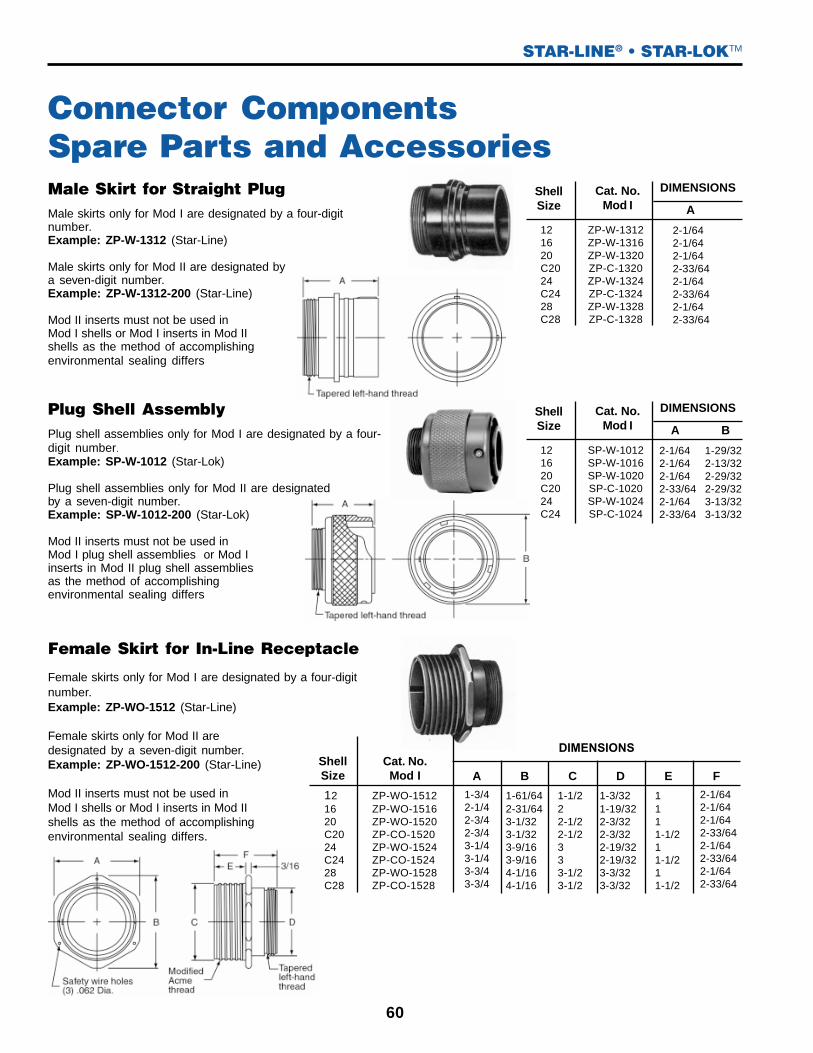
Connector ComponentsSpare Parts and AccessoriesMale Skirt for Straight PlugMale skirts only for Mod I are designated by a four-digitnumber.Example: ZP-W-1312 (Star-Line)
Male skirts only for Mod II are designated bya seven-digit number.Example: ZP-W-1312-200 (Star-Line)
Mod II inserts must not be used inMod I shells or Mod I inserts in Mod IIshells as the method of accomplishingenvironmental sealing differs
ShellSize
Female Skirt for In-Line Receptacle
Female skirts only for Mod I are designated by a four-digitnumber.Example: ZP-WO-1512 (Star-Line)
Female skirts only for Mod II aredesignated by a seven-digit number.Example: ZP-WO-1512-200 (Star-Line)
Mod II inserts must not be used inMod I shells or Mod I inserts in Mod IIshells as the method of accomplishingenvironmental sealing differs.
60
STAR-LINE® • STAR-LOKTM
ShellSize
121620C2024C2428C28
Cat. No.Mod I
ZP-W-1312ZP-W-1316ZP-W-1320ZP-C-1320ZP-W-1324ZP-C-1324ZP-W-1328ZP-C-1328
A
2-1/642-1/642-1/642-33/642-1/642-33/642-1/642-33/64
DIMENSIONS
ShellSize
121620C2024C24
Cat. No.Mod I
SP-W-1012SP-W-1016SP-W-1020SP-C-1020SP-W-1024SP-C-1024
A
2-1/642-1/642-1/642-33/642-1/642-33/64
DIMENSIONS
B
1-29/322-13/322-29/322-29/323-13/323-13/32
Plug Shell AssemblyPlug shell assemblies only for Mod I are designated by a four-digit number.
Example: SP-W-1012 (Star-Lok)
Plug shell assemblies only for Mod II are designatedby a seven-digit number.Example: SP-W-1012-200 (Star-Lok)
Mod II inserts must not be used inMod I plug shell assemblies or Mod Iinserts in Mod II plug shell assembliesas the method of accomplishingenvironmental sealing differs
Cat. No.Mod I A B C D E F
121620C2024C2428C28
ZP-WO-1512ZP-WO-1516ZP-WO-1520ZP-CO-1520ZP-WO-1524ZP-CO-1524ZP-WO-1528ZP-CO-1528
1-3/42-1/42-3/42-3/43-1/43-1/43-3/43-3/4
1-61/642-31/643-1/323-1/323-9/163-9/164-1/164-1/16
1-1/222-1/22-1/2333-1/23-1/2
1-3/321-19/322-3/322-3/322-19/322-19/323-3/323-3/32
1111-1/211-1/211-1/2
2-1/642-1/642-1/642-33/642-1/642-33/642-1/642-33/64
DIMENSIONS

AmphenolINDUSTRIAL
61
Basic Barrel for Panel,Square Flange Receptacle
When mounting two or more receptacles to a panel, a certain distance must bekept, one from the other, so that the coupling nut of one plug does not interferewith the coupling nut of another.
Square flange receptacles only for Mod I are designatedby a four digit number.Example: ZP-WO-1712 (Star-Line)
Square flange receptacles only for Mod II are designatedby a seven digit number.Example: ZP-WO-1712-200 (Star-Line)
Mod II inserts must not be used in Mod I shells or Mod Iinserts in Mod II shells as the method of accomplishingenvironmental sealing differs.
1216
20/C2024/C2428/C28
33-1/24-1/44-3/45-1/4
Shell Size Dim. “A”For mixed-form sizes, adddimension “A” for each anddivide by two.
Connector ComponentsSpare Parts and Accessories
STAR-LINE® • STAR-LOKTM
A
Basic Barrel for Panel,Square Flange ReceptacleSquare flange receptacles only for Mod I are designatedby a four digit number.Example: SP-WO-1712 (Star-Lok)
Square flange receptacles only for Mod II are designatedby a seven digit number.Example: SP-WO-1712-200 (Star-Lok)
Mod II inserts must not be used in Mod I shells or Mod Iinserts in Mod II shells as the method of accomplishingenvironmental sealing differs. Shell
Size HFEDCBA
DIMENSIONSCat. No.
Mod I
3/1613/6417/6417/6417/6417/64
1-3/321-3/321-3/32
1-19/321-3/32
1-19/32
1-3/81-7/82-3/82-3/82-7/82-7/8
2-3/322-3/322-3/32
2-19/322-3/32
2-19/32
1-1/22
2-1/22-1/2
33
1-3/81-11/162-3/322-3/32
2-17/322-17/32
1-3/42-1/42-3/42-3/43-1/43-1/4
SP-WO-1712SP-WO-1716SP-WO-1720SP-CO-1720SP-WO-1724SP-CO-1724
121620
C2024
C24
Drill hole on panel 1/64" larger than Dimension “E” for front mounting or Dimension “C” for back mounting.**Maximum panel thickness may be increased 1/8" when using Standard Coupling Nut Plugs.
ShellSize HG**FEDCBA
DIMENSIONSCat. No.
Mod I
11/6413/647/327/329/329/32
11/3211/32
1/41/41/43/41/43/41/43/4
111
1-1/21
1-1/21
1-1/2
1-3/81-7/82-3/82-3/82-7/82-7/83-3/83-3/8
2-1/642-1/642-1/64
2-33/642-1/64
2-33/642-1/64
2-33/64
1-1/22
2-1/22-1/2
33
3-1/23-1/2
1-3/81-11/162-3/322-3/32
2-17/322-17/323-1/323-1/32
1-3/42-1/42-3/42-3/43-1/43-1/43-3/43-3/4
ZP-WO-1712ZP-WO-1716ZP-WO-1720ZP-CO-1720ZP-WO-1724ZP-CO-1724ZP-WO-1728ZP-CO-1728
121620
C2024
C2428
C28

62
Dimensions
Shell Size
ZP-W-2012-▲-00ZP-W-2016-▲-00ZP-W-2020-▲-00ZP-W-2024-▲-00ZP-W-2028-▲-00
121620 & C2024 & C2428 & C28
Extra Long StyleCat No.
Long StyleCat. No.
Standard StyleCat. No.
ZP-W-2412-▲-00ZP-W-2416-▲-00ZP-W-2420-▲-00ZP-W-2424-▲-00ZP-W-2428-▲-00
ZP-W-2912-▲-00ZP-W-2916-▲-00ZP-W-2920-▲-00ZP-W-2924-▲-00ZP-W-2928-▲-00
Shell Size
ZP-W-2012-▲-53ZP-W-2016-▲-53ZP-W-2020-▲-53ZP-W-2024-▲-53ZP-W-2028-▲-53
121620 & C2024 & C2428 & C28
Extra Long StyleCat No.
Long StyleCat. No.
Standard StyleCat. No.
ZP-W-2412-▲-53ZP-W-2416-▲-53ZP-W-2420-▲-53ZP-W-2424-▲-53ZP-W-2428-▲-53
ZP-W-2912-▲-53ZP-W-2916-▲-53ZP-W-2920-▲-53ZP-W-2924-▲-53ZP-W-2928-▲-53
Shell Size
ZP-W-2012-▲-50ZP-W-2016-▲-50ZP-W-2020-▲-50ZP-W-2024-▲-50ZP-W-2028-▲-50
121620 &C2024 &C2428 &C28
Extra Long StyleCat No.
Long StyleCat. No.
Standard StyleCat. No.
ZP-W-2412-▲-50ZP-W-2416-▲-50ZP-W-2420-▲-50ZP-W-2424-▲-50ZP-W-2428-▲-50
ZP-W-2912-▲-50ZP-W-2916-▲-50ZP-W-2920-▲-50ZP-W-2924-▲-50ZP-W-2928-▲-50
ShellSize
121620 & C2024 & C2428 & C28
3-29/324-5/324-21/325-5/325-21/32
6-5/326-13/326-29/327-13/327-21/32
7-13/327-21/328-5/328-21/328-29/32
1-13/321-29/322-13/322-29/323-13/32
1-1/222-1/233-1/2
1-3/81-7/82-3/82-7/83-3/8
Standard Long Extra Long
AB C D
Cable Adapters Used on Types ZPLD & ZRLD
Cable Adapters Used on Types ZPLM & ZRLM
Cable Adapters Used on Types ZPLK & ZRLK
Taperedleft-handthread
NOTE: Cable adapters with potting ports and molding accesso-ries are also available in all shell sizes-consult factory.
To order cable adapters complete withgrommet, substitute the cable diameter codenumber for the delta ▲ (see page 63).
See cable grip components forbasket weave grip lengths
STAR-LINE® • STAR-LOKTM
A (Nominal) B
CD

AmphenolINDUSTRIAL
4567
7-1/28-1/2
910
4567
7-1/28
63
ZP-6312-2CZP-6312-4CZP-6312-6CZP-6312-8C
ZP-6312-10CZP-6312-12CZP-6312-14CZP-6312-15C
ShellSize Min Max
CableDia.
CodeNo.H
Grommets
Oil-ResistantRubber
Cat. No. Cat. No.
Steel
Gland Washers
Cat. No.
Cable Dia.Dimension
.062 .125
.125 .250
.250 .375
.375 .500
.500 .625
.625 .750
.750 .875
.875 .937
0204060810121415
ZP-5012-4E
ZP-5012-6EZP-5012-8E
ZP-5012-10EZP-5012-12EZP-5012-14EZP-5012-15E
3
12
.250 .375
.375 .500
.500 .625
.625 .750
.750 .875.875 1.000
1.000 1.1251.125 1.2501.250 1.3751.375 1.437
ZP-5016-6EZP-5016-8E
ZP-5016-10EZP-5016-12EZP-5016-14EZP-5016-16EZP-5016-18EZP-5016-20E
06081012141618202223
ZP-6316-6CZP-6316-8C
ZP-6316-10CZP-6316-12CZP-6316-14CZP-6316-16CZP-6316-18CZP-6316-20CZP-6316-22CZP-6316-23C
ZP-8012-4E
ZP-8012-8E
ZP-8012-12E
ZP-8012-15E
ZP-8016-8E
ZP-8016-12E
ZP-8016-16E
ZP-8016-20E
ZP-8016-23E ZP-5016-23E
16
10-1/2
.500 .652
.625 .750
.750 .875.875 1.000
1.000 1.1251.125 1.2501.250 1.3751.375 1.5001.500 1.6251.625 1.7501.750 1.8751.875 1.937
101214161820222426283031
ZP-6320-10CZP-6320-12CZP-6320-14CZP-6320-16CZP-6320-18CZP-6320-20CZP-6320-22CZP-6320-24CZP-6320-26CZP-6320-28CZP-6320-30CZP-6320-31C
ZP-8020-12E
ZP-8020-16E
ZP-8020-20E
ZP-8020-24E
ZP-8020-28E
ZP-8020-31E
ZP-5020-10EZP-5020-14EZP-5020-14EZP-5020-18EZP-5020-18EZP-5020-20E
ZP-5020-24E
ZP-5020-28E
ZP-5020-31E
67-1/27-1/2
99
10
14-1/2
13
11
20or
C20
1.000 1.1251.125 1.2501.250 1.3751.375 1.5001.500 1.6251.625 1.7501.750 1.8751.875 2.0002.000 2.1252.125 2.2502.250 2.3752.375 2.437
.875 1.000
182022242628303234363839
16
ZP-6324-18CZP-6324-20CZP-6324-22CZP-6324-24CZP-6324-26CZP-6324-28CZP-6324-30CZP-6324-32CZP-6324-34CZP-6324-36CZP-6324-38CZP-6324-39C
ZP-6324-16C ZP-8024-16E
ZP-8024-20E
ZP-8024-24E
ZP-8024-28E
ZP-8024-32E
ZP-8024-36E
ZP-8024-39E
ZP-5024-16E
ZP-5024-20E
ZP-5024-24E
ZP-5024-28E
ZP-5024-32E
ZP-5024-36E
ZP-5024-39E
8-1/2
10
11
13
15
16
17-1/2
24or
C24
1.500 1.6251.625 1.7501.750 1.8751.875 2.0002.000 2.1252.125 2.2502.250 2.3752.375 2.5002.500 2.6252.625 2.750
1.375 1.500
2.750 2.875
26283032343638404244
24
46
ZP-6328-26CZP-6328-28CZP-6328-30CZP-6328-32CZP-6328-34CZP-6328-36CZP-6328-38CZP-6328-40CZP-6328-42CZP-6328-44C
ZP-6328-24C
ZP-6328-46C
ZP-8028-24E
ZP-8028-28E
ZP-8028-32E
ZP-8028-36E
ZP-8028-40E
ZP-8028-44E
ZP-8028-46E
ZP-5028-28E
ZP-5028-32E
ZP-5028-36E
ZP-5028-40E
ZP-5028-46E
13
15
16
17-1/2
19
28or
C28
WasherShell DimensionsSize A B
12 1-7/32
16 1-3/4
20 & C20 2-7/32
24 & C24 2-3/4
28 & C28 3-1/4
Seecable dia.
column“A” forcablerange
WasherShell DimensionsSize A E
12 1-1/4
16 1-3/4
20 & C20 2-1/4
24 & C24 2-3/4
28 & C28 3-1/4
Gland Washer
Grommets
Cable GripComponents
Gland washers are not required when grommetsare used with basket weavecable grips.
★ Substitute Symbol No. for ▲ in Cable Adapter Catalog Number
EEx dGlandCableCode Cable RangeA 0.42 - 0.55 (11.0 - 14.3)
ASIS 0.33 - 0.52 (8.5 - 13.4)
B 0.50 - 0.78 (13.0 - 20.0)
BSIS 0.37 - 0.60 (9.5 - 15.4)
C 0.74 - 1.03 (18.8 - 26.2)
CSIS 0.60 - 0.82 (15.4 - 20.8)
C2 0.97 - 1.26 (24.6 - 32.0)
C2SIS 0.86 - 1.09 (21.8 - 27.7)
D 1.22 - 1.73 (31.5 - 44.4)
DSIS 1.07 - 1.35 (27.5 - 34.8)
E 1.65 - 2.19 (42.5 - 56.3)
ESIS 1.52 - 1.81 (27.5 - 34.8)
Unarmored Cable EEx dGland Cable Code
Seecable dia.
column“A” forcablerange
STAR-LINE® Family Series
StainlessSteel
Basket Weave Grips
NominalLengthInches
B A
1 3/16
A E
1/16

Standard and Jacking Coupling Nuts(Star-Line only)
Conduit AdaptersTapped for Conduit
Potting Sleeve
Insert Clamp Nuts
Used with Male Plug Shells
Used when open-back wiring is desired behind panelboards orwithin large junction boxes on which the basic barrel is mounted
For use with insert clamp nut or panel board adapter to accept compound forsealing wire terminals. Potting sleeves are not for use with pressure-typecontact units with insulator extension at back.
For use with all inserts other than those with pressure terminals.Internal tapered pipe thread takes various types of threadedconnectors.
ShellSize
121620 & C2024 & C2428 & C28
121620 & C2024 & C2428 & C28
Cat. No.Std.
ZP-7012-10AZP-7016-10AZP-7020-10AZP-7024-10AZP-7028-10A
JACKZP-7012-30AZP-7016-30AZP-7020-30AZP-7024-30AZP-7028-30A
A B
47/6447/6447/6447/6447/64
1-1/321-1/321-1/321-1/321-1/32
1-13/162-5/162-13/163-5/163-13/16
1-13/162-5/162-13/163-5/163-13/16
DIMENSIONS
ShellSize Cat. No.
Without PottingSleeve
Cat. No.
With Type 8200Potting Sleeve
DIMENSIONS
A B
1216
20 & C2024 & C2428 & C28
ZP-W-7512ZP-W-7516ZP-W-7520ZP-W-7524ZP-W-7528
ZP-W-7512-BZP-W-7516-BZP-W-7520-BZP-W-7524-BZP-W-7528-B
1-11/321-27/321-11/322-27/323-11/32
1-3/321-19/322-3/32
2-19/323-3/32
Cat. No.
ZP-8212-11ZP-8216-11ZP-8220-11ZP-8224-11ZP-8228-11
DIMENSIONS
Overall Length O.D I.D
1-1/41-1/41-1/41-1/41-1/4
1-3/641-35/642-3/642-35/642-63/64
55/641-23/641-55/642-23/642-51/64
ShellSize
1216
20 & C2024 & C2428 & C28
ShellSize
ConduitTapSize
Cat. No.A B C D E
DIMENSIONS
1216
20&C2024&C2428&C28
3/41-1/41-1/2
22-1/2
1-1/22
2-1/23
3-1/2
ZP-W-2812ZP-W-2816ZP-W-2820ZP-W-2824ZP-W-2828
2-5/82-3/42-7/8
33-15/32
1-13/321-29/322-13/322-29/323-13/32
1-3/81-7/82-3/82-7/83-3/8
3/41-1/41-1/2
22-1/2
Safety Wire holes(3) .062 Dia.Modified Acme thread
B Tapered lefthand thread
With Pottingsleeve
PottingSleeve
Insert clampnut
E NPT thread
23/32
64
STAR-LINE® • STAR-LOKTM
AB
1 13/16
A
A B
D C

AmphenolINDUSTRIAL
Cable Adapter Componentsand Accessories
Gland Nut Use plain, or with basket weave cable grip
Mechanical Clamp Nut
ThreadSize
ZP-W-2012ZP-W-2016ZP-W-2020ZP-W-2024ZP-W-2028
121620&C2024&C2428&C28
1-3/8-121-7/8-122-3/8-122-7/8-123-3/8-12
StandardStyle
Cat. No.ShellSize
1-3/81-7/82-3/82-7/83-3/8
6-1/26-3/47-1/47-3/48
5-1/45-1/266-1/26-3/4
33-1/43-3/44-1/44-3/4
ZP-W-2912ZP-W-2916ZP-W-2920ZP-W-2924ZP-W-2928
ZP-W-2412ZP-W-2416ZP-W-2420ZP-W-2424ZP-W-2428
BXLg.Lg.Std.Long Style
Cat. No.
Extra LongStyle
Cat. No.A
DIMENSIONS
22-1/162-1/82-3/162-1/4
7/815/1611-1/161-1/8
1-3/42-1/42-3/43-1/43-3/4
2-3/833-3/44-1/25-1/8
ZP-W-5312ZP-W-5316ZP-W-5320ZP-W-5324ZP-W-5328
121620 & C2024 & C2428 & C28
DCBAShell Size Cat. No.
DIMENSIONS
1-9/321-25/322-9/322-25/323-9/32
1-1/222-1/233-1/2
ZP-7312-10AZP-7316-10AZP-7320-10AZP-7324-10AZP-7328-10A
121620 & C2024 & C2428 & C28
BAShell Size Cat. No.DIMENSIONS
Reversable clampsfor complete cablerange
A Maximum
Tapered left-hand thread
Thread
65
STAR-LINE® • STAR-LOKTM
A
B
A B
1-1/4
B
C
D

1-13/321-29/322-3/82-29/323-11/16
1-3/42-1/42-22/323-7/323-15/16
Panelboard Adapters (Star-Line only)For Basic Barrels. Used when a completely external mounting is required. Gasket furnished may be used for front panelmounting only.
Transition AdaptersTransition adapters provide for using cable adapters one shell size larger than that of the basic barrel selected. They areused when terminating shielded cables require an increase in adapter diameter for additional wiring space.
Safety Jam NutsTo securely lock plug coupling nut or threaded dust cap. Jam nut cannot be used on barrels with hinged spring cover.
Plastic Dust CapsFor temporary protection of assembled barrels while in storage and shipment.
ShellSize
121620 & C2024 & C2428 & C28
Cat. No.ZP-W-2112ZP-W-2116ZP-W-2120ZP-W-2124ZP-W-2128
JHGFEDCB3/167/329/3211/3211/32
1-3/81-7/82-3/82-7/83-3/8
3/425/3213/1627/3227/32
9/169/169/169/1629/64
3/321/85/323/169/32
1-3/321-19/322-3/322-19/322-3/32
1-1/81-5/82-1/82-5/83-1/8
1-1/41-11/162-3/322-17/323-1/32
1-5/82-1/82-5/83-1/83-3/4
A
DIMENSIONS
ShellSize
121620 & C2024 & C2428 & C28
121620 & C2024 & C2428 & C28
LD
DIMENSIONSCat. No.for Plugs
11/1611/1611/1611/161/2
5/811/1621/3221/321/2
ZP-5512-11ZP-5516-11ZP-5520-11ZP-5524-11ZP-5528-11
For ReceptaclesZP-5612-11ZP-5616-11ZP-5620-11ZP-5624-11ZP-5628-11
ShellSize
121620 & C2024 & C24
Cat. No.1620 & C2024 & C2428 & C28
AdapterShellSize
ZP-W-2316-40ZP-W-2320-40ZP-W-2324-40ZP-W-2328-40
A1-3/321-19/322-3/322-19/32
1-19/322-3/322-19/323-3/32
2-15/642-49/643-9/323-15/16
22-1/233-1/2
DCB
DIMENSIONS
ShellSize
121620 & C2024 & C24
ZP-7212-10AZP-7216-10AZP-7220-10AZP-7224-10A
Cat. No. A
1-61/641-31/643-1/323-9/16
1-3/42-1/42-3/43-1/4
B
DIMENSIONS
D Tapered lefthand thread
J hole DIA.
ModifiedAcme thread
66
STAR-LINE®
EF
C
G
H
A Sq.B Sq.
D
L
D
L
B
A1/4

AmphenolINDUSTRIAL
67
Environmental covers are furnished with a six-inch length of stainless steel link chain. The chain is freelyattached to a shouldered swivel post to avoid twisting when covers are applied or removed. The oppositeend has a stainless steel ring for back of barrel attachment or a stainless steel eyelet for flange screw orseparate screw attachment.
APPLICATIONRING TYPE: Slide ring over back end of barrel beforeapplying cable adapter.
EYELET TYPE: Attach eyelet to flange mounting screw ordrill and tap hole in adjacent mounting surface.
Shell Size
Shell Size
Catalog No.With Ring
Catalog No.With Eyelet A D E F G
DIMENSIONS
16
12
20C20
24C24
28C28
_P-W-5512-A _P-WF-5512-A
_P-W-5516-A _P-WF-5516-A
_P-W-5520-A_P-C-5520-A
_P-W-5524-A_P-C-5524-A
ZP-W-5528-AZP-C-5528-A
_P-WF-5520-A_P-CF-5520-A
_P-WF-5524-A_P-CF-5524-A
ZP-WF-5528-AZP-CF-5528-A
1-1/2
2
...11/323-1/41-1/22
...9/322-3/41-1/22
...7/322-1/41-1/22
...
13/641-3/41-1/2
11/641-1/41-1/2
3-1/2
3
2-1/2
...
16
12
20 & C20
24 & C24
28 & C28
_P-W-5612-A _P-WF-5612-A
_P-W-5616-A _P-WF-5616-A
_P-W-5620-A
ZP-W-5624-A
ZP-W-5628-A
_P-WF-5620-A
ZP-WF-5624-A
ZP-WF-5628-A
...
...
3-23/3211/323-1/4
3-7/329/322-3/4...
2-23/327/322-1/4...
1-23/32
13/641-3/4...
11/641-1/4...
...
...
...
2-7/32
...
THREADED CAPS WITH CHAIN FOR USE WITH FEMALE RECEPTACLESCap has a captive gasket for sealing.
Hinged Spring Door Covers-Gasketed
Covers have a stainless steel band to clamp over thecoupling thread of female receptacles. The cover platewith a captive rubber gasket is pressed aluminum.A self-aligning seal is assured by the floating action
of the cover on the center stainless-steel shouldered post.The hinge arm and support are machined aluminumextrusions.
DIMENSIONSShellSize
SHORT HINGED TYPE TO CLEARSTANDARD COUPLING NUT –
USE WITH SQUARE FLANGE RECEPTACLESWHEN FRONT OR BACK MOUNTED
1216
20 & C2024 & C2428 & C28
Cat. No. A B C
ZP-C-5712ZP-C-5716ZP-C-5720ZP-C-5724ZP-C-5728
1-19/321-19/321-41/641-41/641-41/64
1-1/21-3/4
2-9/642-25/64
2-5/8
2-1/22-3/4
3-9/643-25/64
3-5/8
LONG HINGED TYPE TO CLEARCOUPLING JACK NUT –
USE WITH SQUARE FLANGE RECEPTACLESWHEN FRONT MOUNTED ONLY
12†16†20†24†28†
ZP-C-5712-14ZP-C-5716-14ZP-C-5720-14ZP-C-5724-14ZP-C-5728-14
1-23/321-23/321-49/641-49/641-41/64
1-1/21-3/4
2-9/642-25/64
2-5/8
2-1/22-3/4
3-9/643-25/64
3-5/8
6” Chain
Modified acmethread diameter
DIMENSIONSShellSize Cat. No. A B C
ModifiedAcme thread
dia.
Example: ZP-W-5512-A (Starline) SP-W-5512-A (Star-Lok)
Environmental Covers With Chain
STAR-LINE® • STAR-LOKTM
G
A
E
F
1-1/16
D
C
B
A
9/32

68
Type
Straight
3-1/42-5/164-5/162-7/8
1-7/83-1/41-1/24-5/162-7/8
EDCBA
ZP-C-2516-1316
ZP-C-2512-1312
ZP-C-2516-1116
ZP-C-2512-1112
Catalog No.Shell Size
45 Degree
DIMENSIONS (Including Barrels)
1-7/8
Style
FS 2-13/164-9/16N-FS18N-FS28N-FS38
BACatalog
No.
1/23/41
Hub Size
12
Shell SizeC
2-1/16
DIMENSIONS
FD 16 1 N-FD38 4-9/16 2-13/16 3-1/16
Adapter Covers – Cast Aluminum Alloy TakesType ZRLP Barrels
Conduit Fitting Bodies – Die CastCopper-Free Aluminum
Conduit Fitting Bodies – Cadmium PlatedFerrous Alloy
NOTE: 1/2” and 3/4” hub deep junction boxes information available on request.
Conduit SystemAccessoriesFS and FD Conduit Fitting Bodies and Adapters
Adapter covers and Bodies have environmental resistance adequate for mostgeneral applications.
All adapter covers are supplied with screws and clips for mounting receptacle as well as bolts, washers and gasketfor mounting cover to panel or conduit fitting body.
STAR-LINE® • STAR-LOKTM
D
A
B
E
C
C
A
BC

AmphenolINDUSTRIAL
69
Shell Size
20 or C20
24 or C2428 or C28
ConduitHub Size
3/41
1-1/41-1/2
1-1/41-1/2
2
2-1/23
Catalog No.
P-202760-42P-202760-43P-202760-64P-202760-65
JRZ-610064JRZ-610065JRZ-610066
JR-720036-AJRZ-820036-A
A1
5-1/45-1/45-1/45-1/4
666
A2 B F
3-3/44-1/2
3-3/43-3/43-3/4
2-3/82-3/82-3/82-3/8
E
4-1/24-1/24-1/2
4-3164-3/164-3/164-3/16
DC2
5-1/45-1/45-1/4
4-5/84-5/84-5/84-5/8
C1
9/169/169/16
25/6425/6425/6425/64
7/167/16
9/329/329/32
9/329/329/329/32
12 or 16
5-1/45-1/45-1/45-1/4
666
5-1/45-1/45-1/4
4-5/84-5/84-5/84-5/8
SEE DRAWING
DIMENSIONS
Shell Size
ZP-C-2512-12 3-9/16
B
8
8
8
A
P-202708-28
P-202708-24
ZP-C-2520-26
P-202704-16
Deep
ZP-C-2528-12
ZP-C-2524-12
ZP-C-2520-12
ZP-C-2516-12
Standard
28C28
28C28
24C24
24C24
20C20
20C20
16
16
12
4-1/2
3-3/8
3
4-1/16
2-17/32
2-7/16
D
3-33/64
3-33/64
5
5
3-39/64
3-39/64
4-7/16
2-15/16
2-13/16
C
7
7
3-7/8
3-7/8
3-7/8
3-7/8
3-9/16
3-9/16
1/4-20
1/4-20
1/4-20
F
2-21/32
2-19/64
4-7/8
4-9/165-3/47
2-3/43-5/87
7 3-5/8 2-7/16
55-3/47
4-9/165-3/47
4-1/2
4-1/2
4-1/2
4-3/16
4-3/16
4-3/16
8
8
8
8
8
4-1/2
55-3/47
1/4-20
1/4-20
1/4-20
1/4-20
1/2-13
1/2-13
1/2-13
1/2-13
1/2-13
1/2-13
1/2-13
1/2-13
DIMENSIONS (With Barrel)Catalog No.
StyleBA
Cat No.Shell Size
2-9/16
2-1/16
2-1/16
1-27/32
1-27/32
D
1-1/2
1-1/2
1-1/2
1-1/2
1-7/32
1-7/32
1
1
C
7
7
7
7
3-7/8
3-7/8
3-9/16
3-9/16
1/4-20
1/4-20
F
2-25/32
2-9/32
2-27/32
8
4-1/2
4-1/2
4-3/16
4-3/16
8
8
8
1/4-20
1/2-13
1/2-13
1/4-20
1/2-13
1/2-13
DIMENSIONS (With Barrel)
ZP-C-2524-10
ZP-C-2516-10
ZP-C-2528-10
ZP-C-2520-10
ZP-C-2512-10
Above should not be used with pressure-type contact inserts
STANDARD
DEEP
MOUNT WITHHUB AT TOP,BOTTOMOR EITHER SIDE
Conduit Fitting Bodies – – – – – Cadmium Plated Ferrous Alloy
FittingDimensions
Straight
Adapter Covers – Cast Aluminum Alloy Take ZRLPBasic Barrels
12
28 & C28
24 & C24
20 & C20
16
Shell sizes 24-C24-28-C28
Watertight Adapter Covers & Conduit Fitting BodiesAdapter covers and conduit body fittings have environment resistance adequate for most general applications. All adapter coversare supplied with screws and clips for mounting receptacles as well as bolts, washers and gaskets for mounting cover to panel orconduit fitting body.
STAR-LINE® • STAR-LOKTM

70
Contact Crimping Tools
TP-201411-TO-Hand crimp tool only
TP-201411-16-18 – Locator only for #16 and #18 pins and sockets
TP-201411-10-12 – Locator only for #10 pin and sockets and #12 sockets
TP-201411-AG-HAND CRIMP TOOL COMPLETEThis tool is complete with 3 contact Iocators and instructions, and will crimp allcontacts #10 through #18 of the Mod Il and Mod Ill design.
TP-201351-AG – HAND CRIMP TOOLThis tool is complete with carrying case, checking gage and complete instructions forcrimping #10 through #18 contacts of MOD II or MOD Ill design.
TP-201352 – HAND/FOOT PNEUMATIC CRIMP TOOLThis tool is complete with foot control, checking gage, wrench, and complete instructionsfor crimping #10 through #18 contacts of MOD II or MOD III design.
TP-201411-12P – Locator only for all #12 pins any length
TP-201351-TC – HAND CRIMP TOOLThis tool crimps #18 contacts utilizing thermocouple wire.
TP-201351-TL – HAND CRIMP TOOLThis tool crimps #8 contacts only.
T & B TOOL NUMBER 13642 AND DIE NUMBER 11747To terminate 500 MCM contact.
TP-201328 CRIMPING TOOL ONLYAND ACCESSORIES FOR CONTACTS #12 through #4/0
Contact Size
TP-201328-12D
10 W Length10 C Length
8 W Length8 C Length
4 W Length4 C Length
1/0
4/0
12-14
10-12
8-10
4-6
1/0-12
4/0-3/0
12 W Length12 C Length
TP-201328-10G
TP-201328-8D
TP-201328-4D
TP-201328-0DTP-201328-2D
TP-201328-41G
TP-201328-4L
TP-201328-41G
TP-201328-4G
TP-201328-8G
TP-201328-10G
TP-201328-0GTP-201328-2G
Yellow
Green
Blue
Brown
Red
Black
TP-201328-12TP-201328-12C
TP-201328-10TP-201328-10C
TP-201328-8TP-201328-8C
TP-201328-4TP-201328-4C
TP-201328-0C
TP-201328-41
TP-201328-12L
TP-201328-10L
TP-201328-8L
TP-201328-12G
TP-201328-0L
TP-201328-41L
Wire Size Die Number Check Gage Color MOD II MOD III
6’ Air hose
*Foot control(OPTIONAL)
TP-201328-CRIMP TOOL
TP-201328-PS-POWER SUPPLY
TP-201328-BC-CARRYING CASE
NOTE: Carrying case will accommodate crimp tool.
NOTE: Power supply will include 5 dies and locators.
TP-201328-FDie Set
Hand control(STANDARD)
TP-201411-AG
(Locator)
*Foot control unit with 6 foot hose-Cat. No. TP-201328-F. Nominal operation- 100 P.S.I.
STAR-LINE® Family Series

AmphenolINDUSTRIAL
71
MOD III Pin and Socket Removal Tools
Insertion and Removal ToolsRemoval tools are used for extracting contacts from theinset assembly after contacts have been seated. Expandersand taper leads are required for sizes 8, 4, 1/0 MOD IIcontacts only.
A separate expander barrel is required for eachcavity of the contact inset.
An even number of long and short barrels should be used:Example: if the insert contains four cavities, use two long(EBL) and two short (EBS). Insert the short ones first andremove them last.
NOTE: EBS = Expander Barrel Short, EBL= Expander Barrel Long.
Crimp Type ContactsInsertion tools are used for inserting contacts after theyare terminated to conductor. Pin and socket contacts haveidentical terminal ends; the same tool is used for both.
The T-Bar handle should be used in the insertion andextraction of the expander barrel for the 1/0 cavities –only one is required.
One tapered lead required only.
Size Catalog No.Replacement
Tips
TP-201047-1
TP-201048-1TP-201049-1TP-201046-1
16
18
1210
USE SAME TOOLFOR PIN OR
SOCKET
TP 201047 PA
TP 201048 PATP 201049 PATP 201046 PA
Size ExpanderBarrel
T-Bar Handle
TP-201007-A
TP-201033-ATP-201000-EBLTP-201000-EBS
4
8
00
. . . . . . . .TP 201000-TH
. . . . . . . .
TP 201000-TL
TP 201033-BTP 201007-B
Size Pin
TP-201459TP-201459
TP-201459
16
18
1210
TP-201009-3
TP-201011-3TP-201459
TP-201010-3
TP-201008-3
Contact Size Tool No.
Removal Tools for MOD II
Tapered Lead
Socket
STAR-LINE® Family Series
18 TP201315-1816 TP201315-1612 TP201315-1210 TP201315-108 TP201315-084 TP201315-04
1/0 TP201260-00

RIG-Power Connectors (1000v AC/DC)Ampacity Ampacity (Using (Using Wire Connector535 MCM) 777 MCM) Range Style Insert Gender Part Number*
Plug w/ Mech. Clamp Dead Front Pin (Line side) RIG-10P▲-M-◆
Plug w/ Mech. Clamp Socket Contact (Load Side) RIG-10S▲-M-◆
Cable Receptacle w/ Mech. Clamp Dead Front Pin (Line side) RIG-15P▲-M-◆
Cable Receptacle w/ Mech. Clamp Socket Contact (Load Side) RIG-15S▲-M-◆
Fixed Cable Receptacle w/ Mech. Clamp Dead Front Pin (Line side) RIG-17P▲-M-◆
Fixed Cable Receptacle w/ Mech. Clamp Socket Contact (Load Side) RIG-17S▲-M-◆
Panel Mount Receptacle (Bus Bar) Dead Front Pin (Line side) RIG-17PR-▲
Panel Mount Receptacle (Bus Bar) Socket Contact (Load Side) RIG-17SR-▲
Panel Mount Receptacle (Direct Cable Entry) Dead Front Pin (Line side) RIG-17PN-▲
Panel Mount Receptacle (Direct Cable Entry) Socket Contact (Load Side) RIG-17SN-▲
▲ Select Cable Size: (4=444 kcmil, 5=535 MCM, 6 = 646 MCM, 7=777 MCM)
◆ Select Grommet Number from Chart Below* For Basketweave Grip substitute K for MUse Crimp Tool: Anderson (Square D) Versa Crimp # VC8
◆ Color Code OptionsCurrent Type DC AC
Standard Color Code Blue Orange Yellow Brown Red White Black GreenPart No. Suffix ◆ -BL -OR -Y -BR -R -W -BK -G
Single Pole Power Connectors
900 1135 444 -777 kcmil
RIG-POWER Grommet Selection GuideCable Diameter 1.000-1.125 1.125-1.250 1.250-1.375 1.375-1.500 1.500-1.625 1.625-1.750 1.750-1.875Code No.(XX) 18 20 22 24 26 28 30
72
PANEL MOUNT RECEPTACLE RIG-17X
NOTE:See page 19, shell sizeC24 for full mountingdimensions.

AmphenolINDUSTRIAL
P-500™ / PD-501 POWER ConnectorsType of Boot Part #
Ampacity Wire Size Termination Gender Part Number (See Color Code) Cable Sealing Range
900* –––––– Stud Socket P-500126-BS-◆ ––––––– –––––––900* 535MCM Solder Pin PD-501-L TMPC-10-◆ 1.125 - 1.500900• 535MCM Crimp Pin P-500126-P TMPC-10-◆ 1.125 - 1.500325 313MCM Solder Pin PD-501-S TMPC-10-◆ 1.125 - 1.500
Note: Connectors are rated at 1000 Volts AC/DC when mounted on 5" centers.Copper alloy, silver plated contacts for maximum conductivity.Crimp tool required for P-500126-P is Thomas & Betts hex crimp using Tool # 13642M & Die #11747.* When used with 125° C-rated cable.
TMPC™ ConnectorsType of Cable Sealing
Gender Termination Current Range Part Number Wire Size Boot Part No. Range
Socket 7/8" Stud/Panel board 900-1135 amps TMPC-41777-L-◆ n/a n/a n/aSocket 2 Hole Bus Bar 900-1135 amps TMPC-41777-24L n/a n/a n/aPin Crimp 900 amps TPMC-40535-L 444 - 535 kcmil TMPC-10-◆ 1.125 - 1.500Pin Crimp 900-1135 amps TPMC-40777-L 646-777 kcmil TMPC-10-◆ 1.125 - 1.500
Note: TPMC Connectors are rated at 1000 Volts AC/DC when mounted on 5" centers.Material is Copper alloy, silver plated for maximum conductivity and corrosion resistance.Recommended crimping tools are as follows: Anderson Versa Crimp VC8 (four indent).
73

Star-Line EX®
Certified for use up to 1000V AC/DC in a Zone 1-IIC environmentwith IP65 rated sealingcapabilities. This connector seriesoffers solutions to harsh andpotentially explosiveenvironments.
R-Line® SeriesA DIN43 652 rectangular styleindustrial connector, featuresheavy cast aluminum housings.They are manufactured in eithertop or side entry designs andfinished with an epoxy polyesterpowder coating. Connectorhousings provide positive lockinglatches with rapid mating of theplug and receptacle.
MIL-C-5015A medium to heavyweightconnector offering five mountingstyles, nineteen shell sizes andsolder or crimp termination.
74
A-Line® SeriesA low profile, quick-mate,bayonet coupling systemdesigned for commercial andindustrial environments.Used in heavy-duty controland signal applications.
V-Line® SeriesA heavy-duty, multi-pin, metalshell, attachable electricalconnector is designed forcommercial and industrialcontrol and signal applications.The one-piece five-keyed shell,coupling nut, cable adapter,gland and clamp nut areconstructed of high-grademachined aluminum.
P-Lok® SeriesA standard-duty commercialgrade control and signalconnector for use whereMIL-C-5015 commercialconnectors are specified.Constructed of a one-piecekeyed aluminum shell. Featuresa coupling system that providespositive lock between the plugand receptacle with a simpleone-handed push of theconnector.

AmphenolINDUSTRIAL
Industria-Link™An industrial multi-conductorcable assembly that is built toexcel in a variety of industrialapplications. Featuring vibrationresistance, environmentalsealing (IP65 rated) andresistance to most industrialfluids. Available in both staticand continuous flexing cableversions and offered in the mostpopular pin configurations andlengths.
Swiftmate™These connectors feature robustconstruction and a unique pushto mate / pull to unmate couplingsystem. They are a new memberof the connector family and arecompatible with connectorsdesigned to MIL-C-5015specifications.
GT-SeriesA heavy-duty ruggedconnector with quickreverse bayonet coupling.They provide environmentalresistance with a wide varietyof backshell options.
MIL-C-26482A medium size cylindricalconnector featuring quickbayonet coupling, crimp, solderor printed circuit board termination.These connectors are offeredin seven mounting styles andten shell sizes.
75