An Extension of Multhopp s Method of Calculating the Spanwise Loading of Wing.Fuselage Combinations

Page 1
�������������� ����� ������������� ����������������
��

Page 2
Introduction
Welcome to the Polaris seaplane parkflyer! This model is a parkflyer adaptation of Laddie Mikulasko's beautiful North Star seaplane. It features simple sheet foam construction and excellent handling qualities, both in the air and on the water. In flight this model is smooth and stable, yet also very aerobatic. On the water it tracks straight as an arrow and takes off and lands effortlessly. But one of my favorite things about this model is the amazing speed range—with the recommended power setup the top speed is in excess of 70 mph, yet the model slows down well and can plop down into the water at high alpha under full control at less than 10 mph. This allows the model to be flown in very tight spaces if desired, or if you have a bigger flying site you can open it up and enjoy the speed. It handles wind and waves remarkably well, too. This model also flies very well off of grass—takeoffs require only 10-20 feet and it can even taxi and do easy touch and goes off of grass. The Polaris was designed to use a high kV brushless outrunner motor spinning a 6" or 7" diameter prop. Recommended motor setups include:
• Grayson 2212-06 motor, 2100 mAh 11.1V lipo battery, APC 6x4E prop • Littlescreamers Super Park Jet motor, 1320 or 2100 mAh 11.1V lipo battery, APC 7x5E prop • Littlescreamers Park Jet motor, 1320 mAh 11.1V lipo battery, APC 6x4E prop
The prototype model used a Grayson 2212-06 motor and Thunder Power 11.1V 2100 mAh lipo. This setup provides 190 watts per lb, 1.3:1 static thrust-to-weight ratio for unlimited vertical, and 70+ mph top speed—all at a very light wing loading of 8 oz/sq ft. The small 6" diameter prop also minimizes torque effects and allows for a low thrust line to minimize thrust-induced pitch changes. And to top it all off, this motor is very inexpensive ($39.99 for BOTH the motor and ESC!), so any worries about potential water damage are greatly reduced. Note this model was designed to accommodate up to a 7" diameter prop—just mount the motor at the bottom of the firewall if using a 6" prop and at the top of the firewall if using a 7" prop. Like most seaplanes this model has a high thrust line, however, there is very little pitch trim change with throttle. That's primarily because both the motor and horizontal stabilizer are installed at -2 degrees incidence relative to the wing. The only time I've noticed a pitch trim change with throttle is during VERY slow high alpha flying, where going to full throttle quickly will pitch the nose down. Since the elevator is directly in the prop blast there's plenty of control power to correct, but if you just advance the throttle smoothly you won't even have to worry about it. But most of the time you don't have to worry about the high thrust line at all. One of the secrets behind the fantastic slow speed controllability of this model is the location of the prop right in front of the elevator and rudder. This gives this model fantastic slow speed control both in the air and on the water, and also allows some amazingly tight maneuvers if you give a quick blip of throttle along with the control input. I hope you enjoy this model as much as I have! Steve Shumate

Page 3
Building Tips This model can be built using the following types of adhesives:
• Epoxy (with or without microballons) • UHU Creativ for Styrofoam (or UHU POR) • 3M 77 spray adhesive • ProBond (or Gorilla Glue)
Because of the need to build watertight seams but keep the model quick-building and lightweight, my favorite adhesive for the majority of construction on this model is epoxy mixed with microballons. Use slow or quick-set epoxy depending on how much working time you need for each step. Just mix the epoxy in a mixing cup and add enough microballons to provide a putty-like consistency. An added benefit is that microballon-filled epoxy is white in color and matches the color of Depron very well, which helps hide the glue joints. 3M77 is the glue of choice for laminating parts and gluing support strips to the fuselage and nacelle sides. You’ll notice that 3M Gift tape is called out many times in these instructions, since it works very well for hinges, leading edge protection, and general strengthening. When purchasing, make sure to get 3M Gift tape that is sold in the purple container. The 3M Scotch tape sold in the green container doesn’t work nearly as well, nor does common packing tape.
1. Begin construction by cutting out all of the paper parts templates with scissors, trimming them to within approximately 1/8” of the lines. Then test fit all of the templates onto the foam sheet, trying to minimize wasted foam as much as possible. Once you’re satisfied with the arrangement, remove each template individually and spray the back of the template LIGHTLY with 3M 77 spray adhesive. Then replace the template onto the same spot on the foam sheet. Repeat for every template. After all the templates are tacked onto the foam, cut out all the pieces by cutting on the lines with a SHARP hobby knife. To help keep track of the parts, keep the paper templates on each piece until you’re ready to use it.

Page 4
2. Start construction with the wing. First cut the wing spanwise into two pieces at the main spar location. Then cut a slot for the carbon tube spar, making the slot slightly narrower than the diameter of the spar (about 75% as wide). Now press the end of the carbon tube hard against the edge of the foam in the spar slot to create a semi-circular indention in the foam (see top photo at right). This will allow the spar to seat very nicely into the wing. After verifying the fit of the spar, place the wing on a flat surface covered with wax paper. Glue the spar into place using slow-cure epoxy with microballons, and use several pieces of tape to hold the wing pieces together. After everything is aligned, place several heavy books on top of the wing to hold it down flat and let the glue cure (bottom photo).

Page 5
3. Next install the auxiliary spars into the wing. I used 1/32" ply for the spars, but 1x5mm carbon fiber strips would work even better. Just cut a slit with a hobby knife where shown on the wing parts template, apply epoxy to both sides of each spar, and press into place in the wing. Again place heavy books on top of the wing to hold it flat while the glue cures. After the glue has cured, apply a thin film of epoxy to the top and bottom of the wing directly over the auxiliary spars, which adds considerably strength and also waterproofs the ply spars. Cut the ailerons free and use your hinge of choice. I cut a 45 deg bevel in the leading edge of the ailerons and then used 3M Gift tape strips top and bottom to serve as hinges, which is easy and works very well. After the glue has cured, sand the leading edge of the wing to a well-rounded shape and the trailing edge to a slightly tapered shape. Apply a strip of 3M Gift tape around the entire leading edge for smoothness and improved durability (this also helps prevent dings during the remaining construction).

Page 6
4. Now start construction of the fuselage. Begin by gluing the fuselage corner support strips to the fuselage sides using 3M 77 spray adhesive (top photo). To make construction go a little easier, you can pre-form the curves in the fuselage sides by heating the gently with a heat gun or hairdryer and bending them to close to the final shape. Now glue the fuselage bulkheads into place onto one fuselage side. My favorite glue for this step is UHU Creativ. After the glue is dry, glue the two fuselage sides together (UHU Creative is again recommended). Try to keep the fuselage sides as well aligned as possible during this step. Glue in the 3/8" foam support strips on both sides of bulkhead F3 as shown in the middle photo at left. Use a long sanding block to sand the fuselage top and bottom flush (bottom photo).
Page 7
5. Glue the forward fuselage bottom into place using slow-cure epoxy mixed with microballons. Heat-forming this piece to a gentle curve beforehand will ease assembly, but isn't required. Use a healthy amount of glue to ensure it fills the joint to make it watertight. To keep the fuselage straight and well aligned, use tape to hold the parts in place while the glue cures.
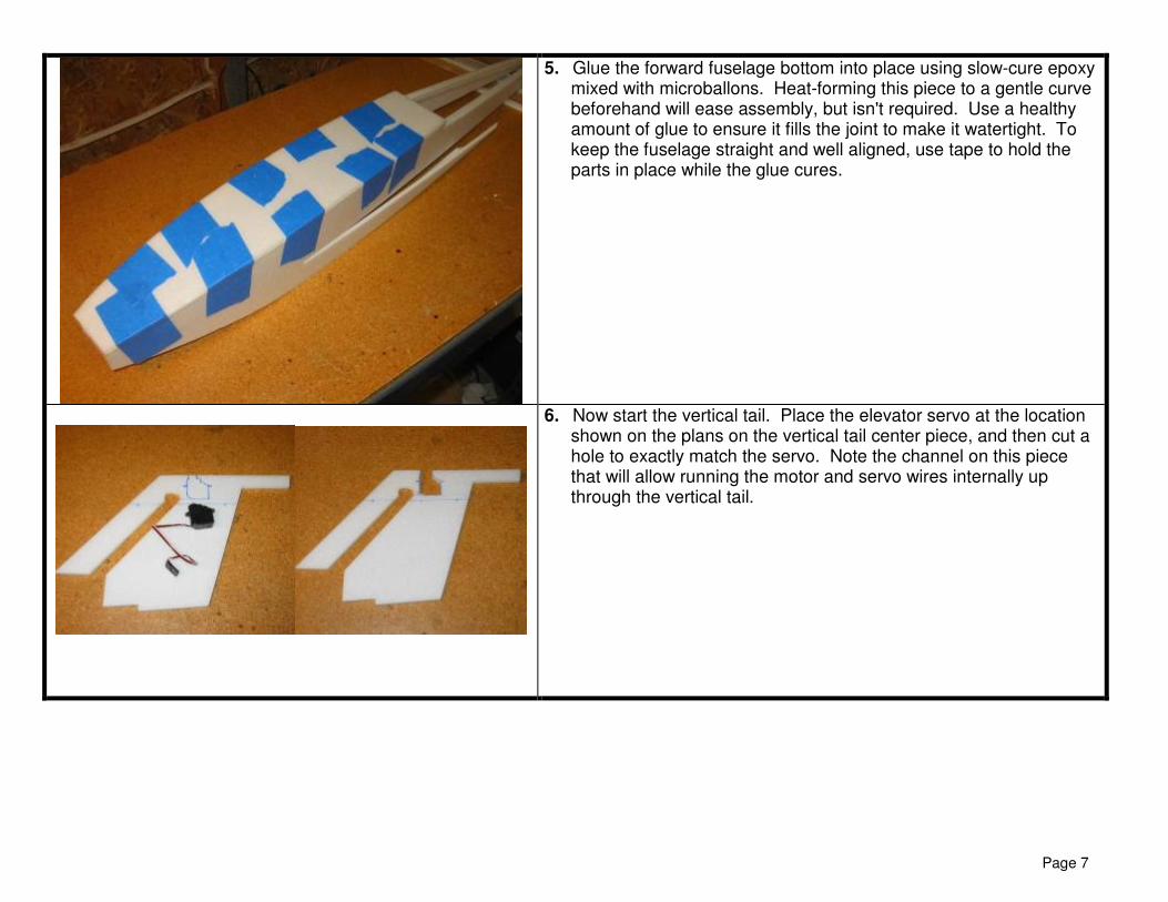
6. Now start the vertical tail. Place the elevator servo at the location shown on the plans on the vertical tail center piece, and then cut a hole to exactly match the servo. Note the channel on this piece that will allow running the motor and servo wires internally up through the vertical tail.

Page 8
7. Laminate the two vertical tail side pieces onto the vertical tail center piece using 3M77. Make sure to align these pieces carefully before laminating them. To prevent getting glue in the channel (which will make installing wire later much more difficult), draw the location of the channel on the inside of the side pieces and place a strip of tape across it before spraying the 3M77 (top photo). Pull off this strip of tape before installation and discard. After the glue has dried, sand a simple airfoil shape into the leading and trailing edges of the vertical tail (bottom photo).
8. Begin construction of the nacelle. Start by cutting/sanding a bevel at the aft end of each nacelle side as shown on the plans. Then glue the support strips where indicated onto the nacelle sides, using 3M77. Then sand the aft edge of the support strips to match the bevel in the nacelle sides. Make sure to make left and right sand pieces. Heat-form the curve in the nacelle sides using a heat gun or hairdryer. Note on the plans the point where the curvature begins—the nacelles are flat forward of this point and don't start curving in until this point (shown by the blue tic marks in the photo at left).

Page 9
9. Glue the nacelle bottom and the assembled right nacelle side to the vertical tail center piece, using epoxy/microballons. Note that the top of the vertical tail side pieces (the parts laminated onto the center piece) are pre-cut to provide a slight amount of downthrust (-2 deg) to the nacelle and horizontal stab, so make sure both the nacelle bottom and sides are properly aligned with the top of the vertical tail side pieces.

Page 10
10. Install the elevator servo into the slot you cut out previously, and thread the servo wire down the vertical tail channel. I used CA to glue the servo in place, followed by a few dabs of epoxy.
11. Glue on the left nacelle side and bulkhead N1 at the same time using epoxy/microballons. Trim the foam as required to clear the servo arm as it rotates.

Page 11
12. Install the elevator pushrod. Poke a hole in nacelle side that is level with the servo horn, and then slide the pushrod into place. I used .047" diameter music wire, and supported the exit hole with a small piece of nylon tubing that was glued in with a dab of epoxy. Use a Z-bend at the servo to provide a solid connection. Leave the aft end of the elevator pushrod blank for now (it will attached to the elevator after the horizontal tail is installed).
13. Sand the bottom corners of the nacelles round as desired. Then glue the 1/8" ply firewall to the front of the nacelle with epoxy. Coat the front and edges of the firewall with a thin coat of epoxy to waterproof it.

Page 12
14. Slide the wing into the wing slot in the fuselage sides, and glue the wing to the bottom edges of the fuselage using epoxy/ microballons. I supported the wing on books and then put weights on top to force the fuselage flat against the wing while the glue cured.
15. Install the battery support tray in the forward fuselage. This piece mates with the wing leading edge inside the fuselage, and runs down to the bottom corner of the fuselage at the nose. Add a strip of Velcro as shown here, which will be used to hold the battery in place.

Page 13
16. Next install the aileron hardware into the wing. I fabricated the linkages from blank 1/16" threaded pushrods, some spare nylon tubing, and Dubro pushrod ends. Cut slots in the top of the wing to clear the nylon tubes and to run the control arms through, and cut slots in the ailerons to seat the torque rod ends (middle photo). Notice in the bottom photo how the control arms extend into the aft fuselage and are placed as close together as possible (this is to allow the motor wires to be routed around these arms as easily as possible in a later step). Once everything is aligned, glue the nylon tubes in place with epoxy/microballons (be careful not to get glue inside the nylon tubes or it will jam them).

Page 14
17. Glue the 1/32" ply vertical tail base support to the top of the wing with epoxy. Make sure to align the slot for the vertical tail center piece.
18. Install the rudder onto the vertical tail. I beveled the leading edge of the rudder 45 deg and then used strips of 3M Gift tape as hinges. Glue the vertical tail assembly into place on the aft fuselage with epoxy/microballons. Note how the vertical tail center piece has a tab that slides into the slot in the wing trailing edge and between the aft fuselage sides. Make sure the vertical tail is perpendicular to the wing as the glue cures. Install the rudder control horn as shown. I used thin plastic sheet for this horn instead of plywood since it will get very wet in use! Note the rudder pushrod will be installed in the next step.

Page 15
19. Next install the aileron and rudder servos and pushrods into the aft fuselage. Begin by gluing the foam servo tray doubler in place with 3M77, then cut holes through the tray and wing to fit the servos used. Note the aileron servo is on the centerline and the rudder servo is offset slightly. The bottom of the servos may stick out from the top of the wing slightly, but that's OK since that area will be covered by the fuselage top later. Glue the servos in place with CA or epoxy. Install the aileron and rudder pushrods. I used 1/16" threaded music wire pushrods for the ailerons (with Dubro pushrod keepers on the aileron ends), and a Sullivan micro flexible pushrod for the rudder (with a Dubro micro-EZ connector at the servo). Solder a short piece of 1/32" music wire to the rudder pushrod on the rudder end, and make a Z-bend to connect it to the rudder control horn. Install the receiver as shown and plug in all the servo wires. I used double-sided tape to hold the receiver in place. I also taped all the servo wires down so they won't flop around in flight.
20. Mount the motor to the firewall with screws. Check that it is properly aligned (-2 deg downthrust, 0 right thrust) and use washers behind the motor mount as necessary to get proper alignment. Note this model was designed to use up to 7" diameter props. If using props 6" diameter (or less), just mount the motor at the bottom of the firewall. If using a 7" prop, mount the motor at the top of the firewall. Cut a small hole on the bottom of the nacelle for the motor wires to enter, and thread the motor wires up through it.

Page 16
21. Now install the motor extension wires and the electronic speed control (ESC). This is one of the more challenging parts of building this model due to the limited space in this area, so study these pictures and think it through carefully. Begin by cutting 3 lengths of 16 gauge wire about 9" long. Solder bullet connectors to one end of those wires. Connect the bullets to the motor wires, and then thread the extension wires down the vertical tail channel from the top (top photo). Snip the extension wires to length on the bottom, and strip the ends (middle photo). Solder the ends to the ESC wires, and then tuck the ESC against the fuselage side (bottom photo). Notice in the bottom photo how the wires are routed around the aileron control arms and the aileron pushrods—two on one side directly to the ESC, and one on the other running underneath the aileron pushrods to the ESC. To gain a little more room around the aileron control arms, I used my fingers to squish in the foam on the inside of the fuselage sides slightly (leaving small indentions in the foam). Use a piece of double-sided tape to hold the ESC firmly against the fuselage side. Install the ESC so that it has plenty of clearance from the aileron pushrods. Arrange the motor extension wires so they have plenty of clearance from the aileron control arms, and then glue the wires in place against the foam to keep them from touching the aileron control arms. Install the servo extension for the elevator servo. Note this extension runs in-between the two aileron control arms, and is glued/taped to the bottom to keep it from moving around.

Page 17
Here's another view showing how the motor wires and elevator servo extension round around the aileron control arms.
22. Install the battery extension wires. Cut two lengths of 16 gage wire to about 16" (note this length can vary depending on what motor/battery combination you use and where the battery ends up being located for balance). Twist these wires together to minimize electromagnetic interference, and then run them from the forward fuselage to the ESC, passing through a small hole cut in the wing. Solder the wires to the ESC in the aft end, and solder the battery connector (Deans Ultra recommended) to the forward end. Glue the wires in place near the servos to keep them from touching the servos (top photo). Next glue the forward fuselage sides in place against the top of the wing with epoxy/microballons (bottom photo). Use the fuselage top piece to gage the curvature required.

Page 18
23. Install the 1/32" ply spars into the horizontal tail, using the same procedure as the wing auxiliary spars. Sand the leading edge to a well-rounded shape and the trailing edge to a slightly tapered shape. Place a strip of 3M Gift tape around the leading and trailing edges to add durability and smoothness. Cut the elevator off and hinge using your method of choice (I used the same beveled edge/3M Gift tape arrangement as on the ailerons and rudder).
24. Use a sanding block to make sure the top of the nacelle is smooth and flush. Test fit the horizontal tail in place and make sure it clears the full range of motion for the elevator servo. Trim as necessary to provide proper clearance (I needed to sand a little foam off the bottom of the horizontal tail right over the elevator servo to keep it from sliding against the foam). Glue the horizontal tail in place on top of the nacelle using epoxy/microballons. Make sure the two ply spars are especially well glued to the nacelle, since they provide extra lateral support for the horizontal tail.

Page 19
25. Sand the leading edge of the vertical fin top to a well-rounded shape and the trailing edge to a slightly tapered shape. Place a strip of 3M Gift tape around the leading edge to add durability and smoothness. Test fit the vertical tail top and make sure it fits well. Note the tab in the vertical fin fits into the slot in the horizontal tail. When satisfied with the fit, glue the vertical fin top in place making sure it is perpendicular to the horizontal tail. Now sand the upper corners of the nacelles to shape, rounding the corners if desired.
26. Glue in the elevator control horn and attach the elevator pushrod. I used a simple 90 deg bend along with a Dubro pushrod keeper. To waterproof the elevator pushrod exit, work some Vaseline into the tubing at the exit. Do the same for the rudder pushrod exit and the aileron torque rods.

Page 20
27. Bevel the aft edge of the fuselage top piece as shown on the plans. Test fit this piece and trim as necessary. Heat-forming the gentle curve in this piece before assembly will make assembly easier, but isn't required. Glue on the fuselage top piece with epoxy/microballons, holding it in place with tape as the glue cures.
28. Laminate the nose cone pieces with 3M77 spray adhesive. Then glue the nosecone block to the forward fuselage with epoxy. Trace the nosecone top template onto the top of the nosecone block, and then rough cut to shape. Then use sandpaper to shape the rest of the nosecone.

Page 21
29. Verify all the electronics work well, since once the aft fuselage bottom is installed it will be difficult to access this compartment. If there are no problems, glue the aft fuselage bottom in place with epoxy/microballons. Use a healthy amount of glue to ensure it fills the joint to make it watertight. Use tape to hold the parts in place while the glue cures. After the glue cures, apply a small fillet of epoxy/microballons to the entire wing/fuselage intersection to ensure it is waterproof.
30. Laminate the wing tip floats with 3M77 glue. Sand to shape and epoxy onto the tips of the wings.

Page 22
31. Test balance to see where the battery needs to be located to provide the recommended CG. Once the battery location is determined, cut a hatch in the forward fuselage top at that location for battery access. Glue in 3/8" wide strips of 1/32" ply to serve as ledges underneath the hatch (I used UHU Creativ). Then use strips of 3M Gift tape on all four edges to keep the hatch on in flight. Although the tape will need to be replaced after every flight, the advantage of this setup is that it provides a very watertight hatch that is easy and quick to open. Hint: Make sure to fold over one end of the tape to allow pulling it off easily after each flight.
32. Final sand the airplane, sanding all the corners flush and rounding the top corners of the fuselage if desired (I recommend leaving the bottom fuselage edges sharp to provide better tracking on the water). CONGRATULATIONS! Your model is now complete. The airplane can be flown as is with bare foam, or you can go ahead and apply your finish of choice.

Page 23
FINISHING TIPS The Depron foam used on this model can be finished with paint, low temp iron-on film, or colored packing tape. The finish on the prototype is just bare foam with colored packing tape for trim. This keeps the model very light, quick to build, and also makes it easy to repair. Plus the packing tape is strategically placed in areas that need to be strengthened anyway for a seaplane—the bottom of the fuselage and the leading edges of the wings and tail. Hence this paint scheme! The model can also be painted with common acrylic craft paints, applied with either a brush or airbrush. If you chose to paint, here are a few tips:
•••• Wipe the entire model with rubbing alcohol before painting to remove all grease and dirt.
•••• Rough areas should be filled with lightweight wall spackling compound thinned with water, which fills the holes and can be sanded to a very smooth finish with minimal weight gain.
•••• Primer isn’t required over Depron, but applying a coat of water-based polyurethane (WBPU) will help seal the foam and provide a smoother finish. Mixing some microballons or baby powder in with the WBPU will help fill holes even better and improves the finish further.
•••• When thinning acrylic paint for use in an airbrush, thin roughly 50/50 with windshield wiper fluid. The wiper fluid will allow the paint to dry faster (relative to thinning with water), which reduces the chance of runs. It will not affect the finish.
•••• Decals can be made on a computer and printed onto standard label paper using an inkjet or color laser printer.
•••• To seal and waterproof the paint, apply one or two finish coats of WBPU over the entire airframe.
Good luck, and I hope you enjoy this model as much as I have!

Page 24
Flight Setup 1 Adjust the flight controls to provide the following recommended deflections (all measured at the root trailing edge):
• Elevator: +/- 1.0" (40% exponential) • Ailerons: +/- 0.75" (40% exponential) • Rudder: +/- 1.25" (25% exponential)
3. The recommended CG location is 7.69” (7 11/16") ahead of the centerline of the carbon tube wing spar (see the plans).
4. Taxiing on the water is very straightforward. The model tracks well and steers easily with rudder inputs, in large part because the
rudder is located in the prop slipstream. To take off just add throttle and slight back pressure on the stick, and the model will leap off the water in just about 10 ft. Or you can bring the throttle up slowly and fly it off the water gracefully.
5. You’ll find this model is smooth and well-mannered in the air, with no bad habits. But it's also capable of excellent aerobatics! 6. Landings are easy. You can either fly the model onto the water for a gentle skipping landing, or you can flare hard and watch the
airplane plop into the water with remarkably little forward speed and a landing run of only a few feet. Because of the delta wing design and the wing leading edge strakes, this model can pitch up very nose high during landings with no fear of tip stall. Just remember that when flying at high angles of attack the drag is very high, so you'll need to carry a little throttle to keep the model from descending too rapidly.
7. For much more information about this model, check out the online discussion thread on RCGroups at the link below:
http://www.rcgroups.com/forums/showthread.php?t=922465

Page 25
Technical Specifications Wing area: 343 sq in Span: 29.0" Length: 38.4" Weight RTF: 18 to 22 oz (prototype weighed 20 oz ) Wing loading: 8.4 oz/sq ft Motor: Grayson 2212-06 (used on prototype) Battery: Thunder Power 2100 mAh 11.1V Prolite Prop: APC 6x4 Current: 22 amps Watts: 240 watts Power loading: 190 watts/lb Speed control: Grayson 30 amp Receiver: Berg 7P Flight controls: Elevator, ailerons, rudder