Composite Underbody Attachment - Department of...
31
1 Managed by UT-Battelle for the Department of Energy Presentation_name Composite Underbody Attachment Principle Investigator: B. J. Frame Presenter: R. E. Norris Oak Ridge National Laboratory June 7-11, 2010 Project ID #LM024 This presentation does not contain any proprietary, confidential, or otherwise restricted information
Transcript of Composite Underbody Attachment - Department of...
1 Managed by UT-Battellefor the Department of Energy Presentation_name
Composite Underbody Attachment
Principle Investigator: B. J. FramePresenter: R. E. Norris
Oak Ridge National LaboratoryJune 7-11, 2010
Project ID #LM024 This presentation does not contain any proprietary, confidential, or otherwise restricted information
2 Managed by UT-Battellefor the Department of Energy Presentation_name
Overview
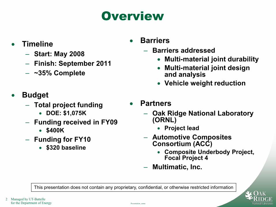
• Timeline– Start: May 2008– Finish: September 2011– ~35% Complete
• Budget– Total project funding
• DOE: $1,075K– Funding received in FY09
• $400K– Funding for FY10
• $320 baseline
• Barriers– Barriers addressed
• Multi-material joint durability• Multi-material joint design
and analysis• Vehicle weight reduction
• Partners– Oak Ridge National Laboratory
(ORNL)• Project lead
– Automotive Composites Consortium (ACC) • Composite Underbody Project,
Focal Project 4– Multimatic, Inc.
This presentation does not contain any proprietary, confidential, or otherwise restricted information
3 Managed by UT-Battellefor the Department of Energy Presentation_name
Background• Technologies for attachment, or joining, of PMC parts to the vehicle’s other
(metallic) components enables the wide-spread integration of structural composites into vehicle design and manufacture – REDUCING VEHICLE WEIGHT
• Issues associated with multi-material joint design include long-term reliability (durability) and manufacture
• Generic tools for predicting the performance of any composite joint design do not exist
• Validated modeling tools must be created to allow OEMS to predict the durability of composite structures with the same level of confidence as metal structures
• The joint and materials to be used in the PMC underbody must be studied for this particular application
• The methodology can be made applicable to other types of multi-material joints, including other material combinations
• This project is the first step toward achieving these goals
This presentation does not contain any proprietary, confidential, or otherwise restricted information
4 Managed by UT-Battellefor the Department of Energy Presentation_name
Objectives
Develop a methodology that will enable prediction of the effects of environmental exposures and mechanical loadings on the durability of a composite/adhesive/metal (multi-material) joint
Focus application: The joining of a polymer matrix composite (PMC) underbody to the rest of the vehicle structure
This project is a collaborative effort on the Composite Underbody project (Focal Project 4) between the Automotive Composite Consortium (ACC), Multimatic, Inc and ORNL
This presentation does not contain any proprietary, confidential, or otherwise restricted information
5 Managed by UT-Battellefor the Department of Energy Presentation_name
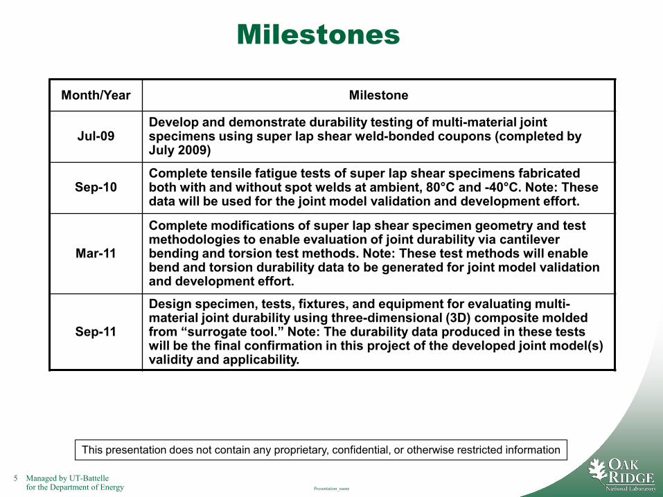
Milestones
This presentation does not contain any proprietary, confidential, or otherwise restricted information
Month/Year Milestone
Jul-09Develop and demonstrate durability testing of multi-material joint specimens using super lap shear weld-bonded coupons (completed by July 2009)
Sep-10Complete tensile fatigue tests of super lap shear specimens fabricated both with and without spot welds at ambient, 80°C and -40°C. Note: These data will be used for the joint model validation and development effort.
Mar-11
Complete modifications of super lap shear specimen geometry and test methodologies to enable evaluation of joint durability via cantilever bending and torsion test methods. Note: These test methods will enable bend and torsion durability data to be generated for joint model validation and development effort.
Sep-11
Design specimen, tests, fixtures, and equipment for evaluating multi-material joint durability using three-dimensional (3D) composite molded from “surrogate tool.” Note: The durability data produced in these tests will be the final confirmation in this project of the developed joint model(s) validity and applicability.
6 Managed by UT-Battellefor the Department of Energy Presentation_name
Approach/Strategy
• Validate and develop the analytical models and tools capable of predicting multi-material joint performance and durability under multiple loading scenarios
• Generate an experimental data base of the multi-material joint’s performance and durability under various loading and environmental conditions to support and validate the modeling approach
• Establish and define the bounds of validity for the methodology
• Combination approach– Modeling and analysis– Physical testing
This presentation does not contain any proprietary, confidential, or otherwise restricted information
7 Managed by UT-Battellefor the Department of Energy Presentation_name
Interactions/Collaborations
• ORNL: Project lead, test method development, durability testing, TMAC dynamic tension testing
• ACC: Technical consultation regarding automotive industry needs and requirements, material characterization, test specimen fabrication
• Multimatic, Inc.: Joint finite element (FE) analyses, CAE model validation and development
This presentation does not contain any proprietary, confidential, or otherwise restricted information
8 Managed by UT-Battellefor the Department of Energy Presentation_name
Two Phases• Phase 1: Simple load cases with small coupons
– “Super lap shear” weld bonded specimen• Tensile loading (shear stress-dominated)• Cantilever bending (peel stress-dominated)• Torsion (combination peel-and-shear stress)
• Phase 2: Replicate and combine load cases with larger sub-structural specimen– “Surrogate tool” composite
• Identified by GM personnel as a suitable substitute for providing molded composite constituent of joint specimen
• Design of surrogate specimen and tests are on-hold pending results of Phase 1 effort
This presentation does not contain any proprietary, confidential, or otherwise restricted information
9 Managed by UT-Battellefor the Department of Energy Presentation_name
Model Validation and Development
• Multimatic, Inc.– Identify how best to model this material/structure – Validate current automotive models ability to predict durability for
mixed material structures – Experimental test data to be used for validations
• Both Phase 1 (“simple”) and Phase 2 (“complex”)– Two or more single load cases– Combination load conditions (stress and environment)– Iterative process between analysis-and-test
This presentation does not contain any proprietary, confidential, or otherwise restricted information
10 Managed by UT-Battellefor the Department of Energy Presentation_name
AccomplishmentsFY09-FY10
• Milestone: Develop and demonstrate durability testing of multi-material joint specimens using super lap shear weld-bonded coupons (completed by July 2009)
• Conducted tensile fatigue tests of super lap shear specimens fabricated with and without spot welds at ambient, 80°C and -40°C. Data files, photos, plots and videos forwarded to Multimatic, Inc
• Prepared test fixtures and equipment to evaluate weld bonded specimens via cantilever bending and torsion test methods.
• Designed grips and generated software drive files to enable dynamic (high strain rate) tensile tests of joint specimens using the Test Machine for Automotive Crashworthiness (TMAC). (The TMAC is part of the ORNL User Facility.)
• Conducted failure analyses of weld bonded composite-to-steel torsion specimens using infrared (IR) thermography method. (IR thermography is a capability of the ORNL User Facility)
This presentation does not contain any proprietary, confidential, or otherwise restricted information
11 Managed by UT-Battellefor the Department of Energy Presentation_name
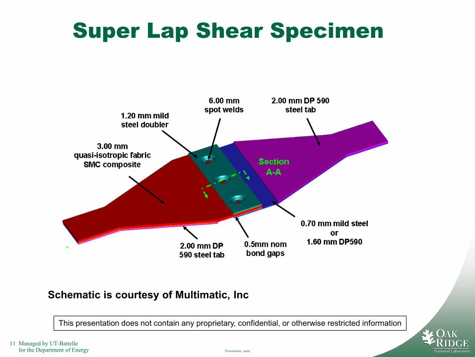
Super Lap Shear Specimen
Schematic is courtesy of Multimatic, Inc
This presentation does not contain any proprietary, confidential, or otherwise restricted information
12 Managed by UT-Battellefor the Department of Energy Presentation_name
Tensile Fatigue
This presentation does not contain any proprietary, confidential, or otherwise restricted information
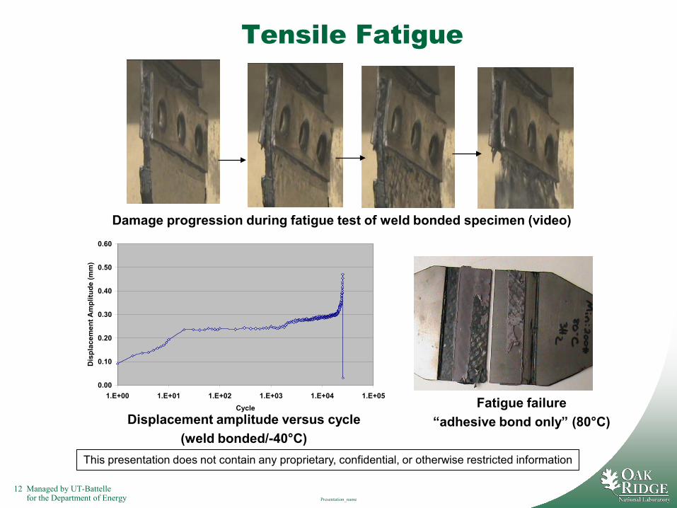
Damage progression during fatigue test of weld bonded specimen (video)
Displacement amplitude versus cycle (weld bonded/-40°C)
Fatigue failure “adhesive bond only” (80°C)
0.00
0.10
0.20
0.30
0.40
0.50
0.60
1.E+00 1.E+01 1.E+02 1.E+03 1.E+04 1.E+05Cycle
Dis
plac
emen
t Am
plitu
de (m
m)
13 Managed by UT-Battellefor the Department of Energy Presentation_name
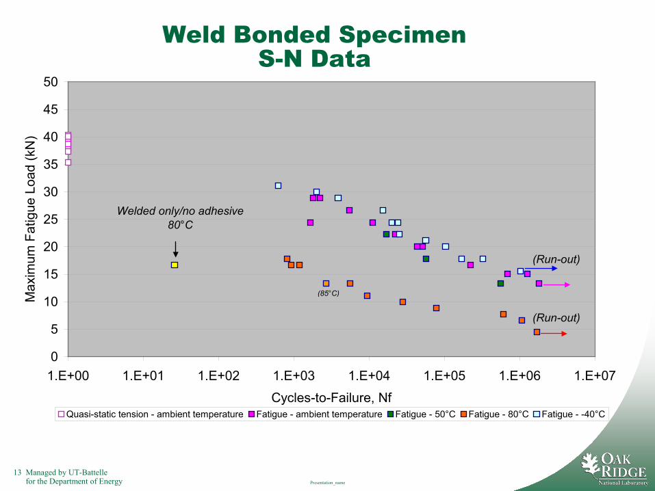
Weld Bonded SpecimenS-N Data
0
5
10
15
20
25
30
35
40
45
50
1.E+00 1.E+01 1.E+02 1.E+03 1.E+04 1.E+05 1.E+06 1.E+07
Cycles-to-Failure, Nf
Max
imum
Fat
igue
Loa
d (k
N)
Quasi-static tension - ambient temperature Fatigue - ambient temperature Fatigue - 50°C Fatigue - 80°C Fatigue - -40°C
(Run-out)
(85°C)
(Run-out)
Welded only/no adhesive 80°C
14 Managed by UT-Battellefor the Department of Energy Presentation_name
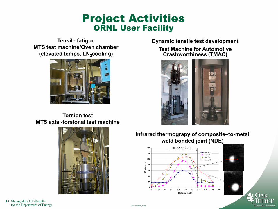
Project ActivitiesORNL User Facility
Dynamic tensile test developmentTest Machine for Automotive
Crashworthiness (TMAC)
Torsion testMTS axial-torsional test machine
0
50
100
150
200
250
300
350
0 0.05 0.1 0.15 0.2 0.25 0.3 0.35 0.4 0.45 0.5
Distance (inch)
IR In
tens
ity
Frame 1Frame 2Frame 5Frame 10
0.2277 inch
Infrared thermograpy of composite–to-metal weld bonded joint (NDE)
Tensile fatigueMTS test machine/Oven chamber
(elevated temps, LN2cooling)
15 Managed by UT-Battellefor the Department of Energy Presentation_name
Future Work
• Complete tensile fatigue tests of super lap shear specimens fabricated with and without spot welds at ambient, 80°C and -40°C. These data will be used for the joint model validation and development effort. Milestone: September 2010
• Continue and complete modifications to super lap shear specimen geometry and test methodologies to enable evaluation of joint durability via cantilever bending and torsion test methods.
• Evaluate validity of durability analytical models with weld bonded and adhesively bonded specimen test data and make modifications to models as appropriate
• Conduct dynamic tensile tests of composite-to-steel joint specimens using the TMAC.
• Design specimen, tests, fixtures, and equipment for evaluating multi-material joint durability using three-dimensional (3D) composite molded from surrogate tool.
• Continue validation and development of durability analytical models using test data from surrogate tool specimens as input
This presentation does not contain any proprietary, confidential, or otherwise restricted information
16 Managed by UT-Battellefor the Department of Energy Presentation_name
Summary• Project objectives
– Develop a methodology to enable prediction of the effects of environmental exposures and mechanical loadings on the durability of a composite/adhesive/metal (multi-material) joint
– Enables the wide-spread integration of structural composites into vehicle design and manufacture – REDUCING VEHICLE WEIGHT
– The methodology can be made applicable to other types of multi-material joints, including other material combinations
– Focus application - The joining of a polymer matrix composite (PMC) underbody to the rest of the vehicle structure
• Combination approach– Modeling and analysis
• Validate and develop the analytical models and tools capable of predicting multi-material joint performance and durability under multiple loading scenarios
• Establish and define the bounds of validity for the methodology– Physical testing
• Generate an experimental data base of the multi-material joint’s performance and durability under various loading and environmental conditions to support and validate the modeling approach
• This project is a collaborative effort on the Composite Underbody project (Focal Project 4) between the Automotive Composite Consortium (ACC), Multimatic, Inc and ORNL
This presentation does not contain any proprietary, confidential, or otherwise restricted information
Managed by UT-Battellefor the Department of Energy
Advanced Preforming and Related Processes for Manufacturing Low
Cost Composites
DOE 2010 Annual Merit Review
R. E. Norris, PI
Oak Ridge National Laboratory
June 7-11, 2010
This presentation does not contain any proprietary, confidential, or otherwise restricted information
Project ID: LM-024-NorrisAgreement Number: 9223
18 Managed by UT-Battellefor the Department of Energy
This presentation does not contain any proprietary, confidential, or otherwise restricted information
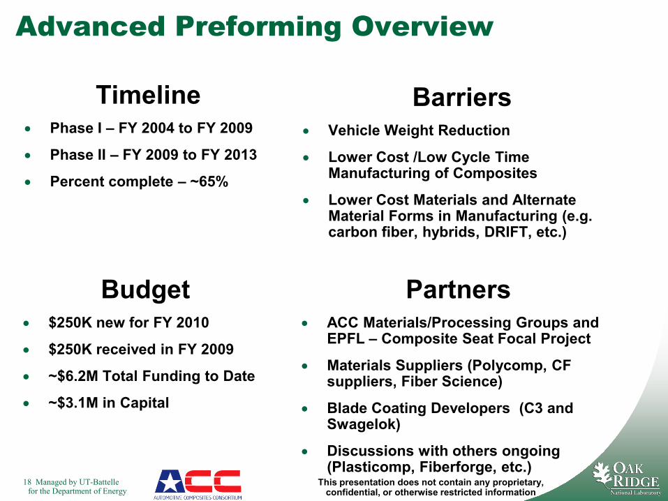
Timeline• Phase I – FY 2004 to FY 2009
• Phase II – FY 2009 to FY 2013
• Percent complete – ~65%
Advanced Preforming Overview
Budget• $250K new for FY 2010
• $250K received in FY 2009
• ~$6.2M Total Funding to Date
• ~$3.1M in Capital
Barriers• Vehicle Weight Reduction
• Lower Cost /Low Cycle Time Manufacturing of Composites
• Lower Cost Materials and Alternate Material Forms in Manufacturing (e.g. carbon fiber, hybrids, DRIFT, etc.)
Partners• ACC Materials/Processing Groups and
EPFL – Composite Seat Focal Project
• Materials Suppliers (Polycomp, CF suppliers, Fiber Science)
• Blade Coating Developers (C3 and Swagelok)
• Discussions with others ongoing (Plasticomp, Fiberforge, etc.)
19 Managed by UT-Battellefor the Department of Energy
This presentation does not contain any proprietary, confidential, or otherwise restricted information
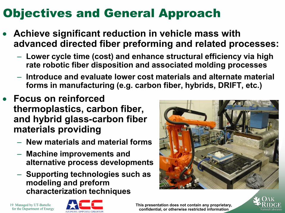
Objectives and General Approach• Achieve significant reduction in vehicle mass with
advanced directed fiber preforming and related processes:– Lower cycle time (cost) and enhance structural efficiency via high
rate robotic fiber disposition and associated molding processes– Introduce and evaluate lower cost materials and alternate material
forms in manufacturing (e.g. carbon fiber, hybrids, DRIFT, etc.)
• Focus on reinforced thermoplastics, carbon fiber, and hybrid glass-carbon fiber materials providing– New materials and material forms – Machine improvements and
alternative process developments– Supporting technologies such as
modeling and preform characterization techniques
20 Managed by UT-Battellefor the Department of Energy
This presentation does not contain any proprietary, confidential, or otherwise restricted information
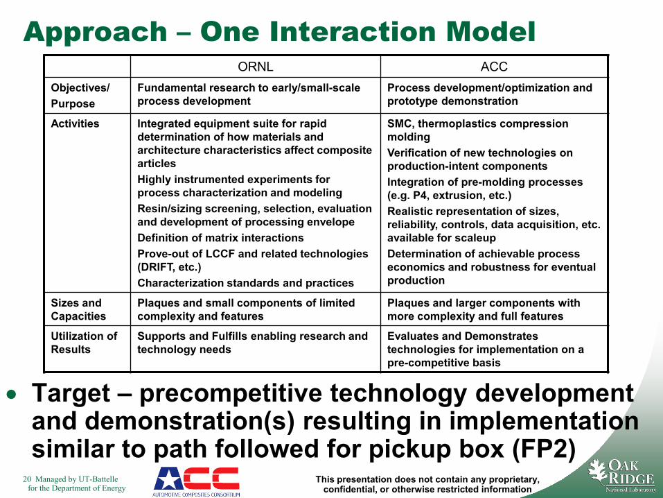
Approach – One Interaction Model
• Target – precompetitive technology development and demonstration(s) resulting in implementation similar to path followed for pickup box (FP2)
ORNL ACCObjectives/Purpose
Fundamental research to early/small-scale process development
Process development/optimization and prototype demonstration
Activities Integrated equipment suite for rapid determination of how materials and architecture characteristics affect composite articlesHighly instrumented experiments for process characterization and modelingResin/sizing screening, selection, evaluation and development of processing envelopeDefinition of matrix interactionsProve-out of LCCF and related technologies (DRIFT, etc.)Characterization standards and practices
SMC, thermoplastics compression moldingVerification of new technologies on production-intent componentsIntegration of pre-molding processes (e.g. P4, extrusion, etc.)Realistic representation of sizes, reliability, controls, data acquisition, etc. available for scaleupDetermination of achievable process economics and robustness for eventual production
Sizes and Capacities
Plaques and small components of limited complexity and features
Plaques and larger components with more complexity and full features
Utilization of Results
Supports and Fulfills enabling research and technology needs
Evaluates and Demonstrates technologies for implementation on a pre-competitive basis

21 Managed by UT-Battellefor the Department of Energy
This presentation does not contain any proprietary, confidential, or otherwise restricted information
Preforming Technical Issues/Drivers
• Focal Project 3 analysis had indicated:– >60% mass savings for minimum thickness of 1.5mm– Carbon fiber utilization is critical to overall objectives– 15% greater mass savings potential for 1mm min.
thickness• Liquid molding applicable, but problematic for very
thin sections• Thermoplastic preforms offer:
– Potential for thinner sections – mass savings– Potential for increased recycling opportunities
• Glass and Carbon hybrids offer:– Cost-saving potential– “Synergistic” properties– Ability to introduce and gain experience with carbon fiber
at lower quantities than for all-carbon parts• Many fundamental issues not understood, e.g.,
– Anisotropy– Optimal product form
22 Managed by UT-Battellefor the Department of Energy
This presentation does not contain any proprietary, confidential, or otherwise restricted information
MilestonesMonth/Year Milestone
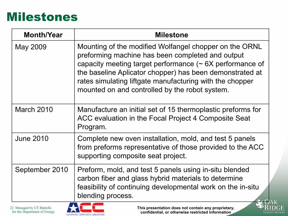
May 2009 Mounting of the modified Wolfangel chopper on the ORNL preforming machine has been completed and output capacity meeting target performance (~ 6X performance of the baseline Aplicator chopper) has been demonstrated at rates simulating liftgate manufacturing with the chopper mounted on and controlled by the robot system.
March 2010 Manufacture an initial set of 15 thermoplastic preforms for ACC evaluation in the Focal Project 4 Composite Seat Program.
June 2010 Complete new oven installation, mold, and test 5 panels from preforms representative of those provided to the ACC supporting composite seat project.
September 2010 Preform, mold, and test 5 panels using in-situ blended carbon fiber and glass hybrid materials to determine feasibility of continuing developmental work on the in-situ blending process.
23 Managed by UT-Battellefor the Department of Energy
This presentation does not contain any proprietary, confidential, or otherwise restricted information
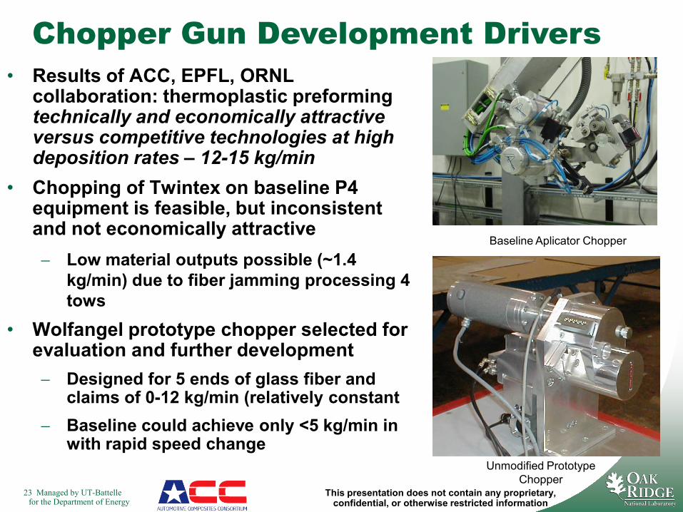
Chopper Gun Development Drivers• Results of ACC, EPFL, ORNL
collaboration: thermoplastic preforming technically and economically attractive versus competitive technologies at high deposition rates – 12-15 kg/min
• Chopping of Twintex on baseline P4 equipment is feasible, but inconsistent and not economically attractive− Low material outputs possible (~1.4
kg/min) due to fiber jamming processing 4 tows
• Wolfangel prototype chopper selected for evaluation and further development− Designed for 5 ends of glass fiber and
claims of 0-12 kg/min (relatively constant− Baseline could achieve only <5 kg/min in
with rapid speed changeUnmodified Prototype
Chopper
Baseline Aplicator Chopper
24 Managed by UT-Battellefor the Department of Energy
This presentation does not contain any proprietary, confidential, or otherwise restricted information
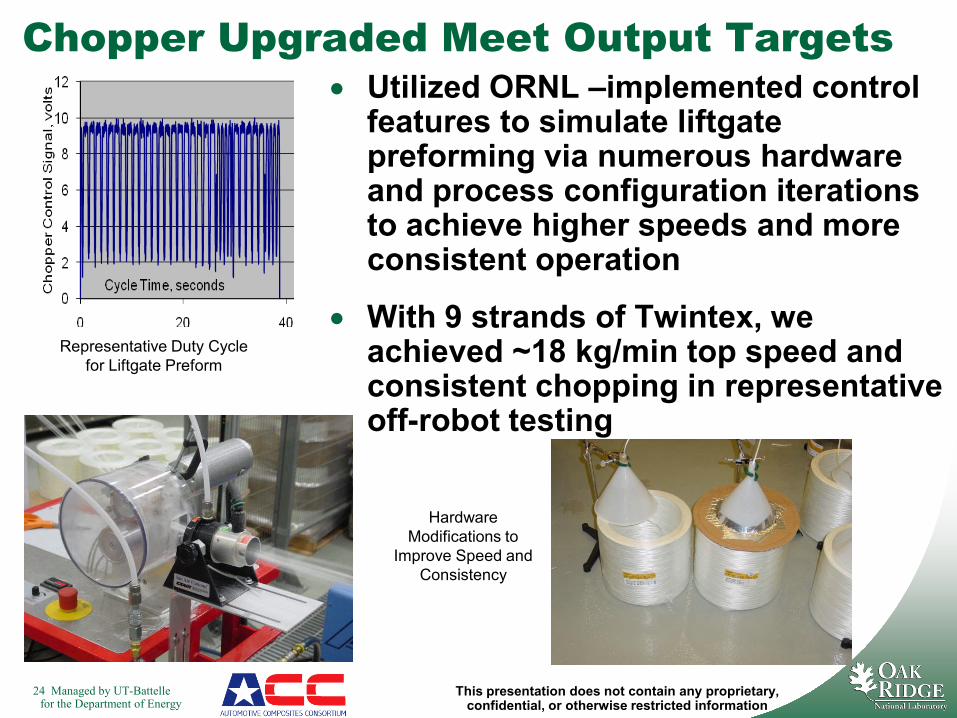
Chopper Upgraded Meet Output Targets• Utilized ORNL –implemented control
features to simulate liftgate preforming via numerous hardware and process configuration iterations to achieve higher speeds and more consistent operation
• With 9 strands of Twintex, we achieved ~18 kg/min top speed and consistent chopping in representative off-robot testing
Representative Duty Cycle for Liftgate Preform
Hardware Modifications to
Improve Speed and Consistency
25 Managed by UT-Battellefor the Department of Energy
This presentation does not contain any proprietary, confidential, or otherwise restricted information
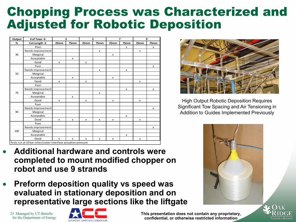
Chopping Process was Characterized and Adjusted for Robotic Deposition
Output # of Tows →% Cut Length → 25mm 75mm 25mm 75mm 25mm 75mm 25mm 75mm
Poor x xNeeds Improvement x x
30 Marginal xAcceptable x
Good x xPoor x
Needs Improvement x x50 Marginal
Acceptable x xGood x x xPoor
Needs Improvement x x70 Marginal x
Acceptable xGood x x x xPoor
Needs Improvement x90 Marginal
Acceptable xGood x x x x x xPoor
Needs Improvement x100 Marginal
Acceptable xGood x x x x x x
Tests run at 10 bar roller/cutter interface actuation pressure
3 5 7 9
• Additional hardware and controls were completed to mount modified chopper on robot and use 9 strands
• Preform deposition quality vs speed was evaluated in stationary deposition and on representative large sections like the liftgate
High Output Robotic Deposition Requires Significant Tow Spacing and Air Tensioning in Addition to Guides Implemented Previously
26 Managed by UT-Battellefor the Department of Energy
This presentation does not contain any proprietary, confidential, or otherwise restricted information
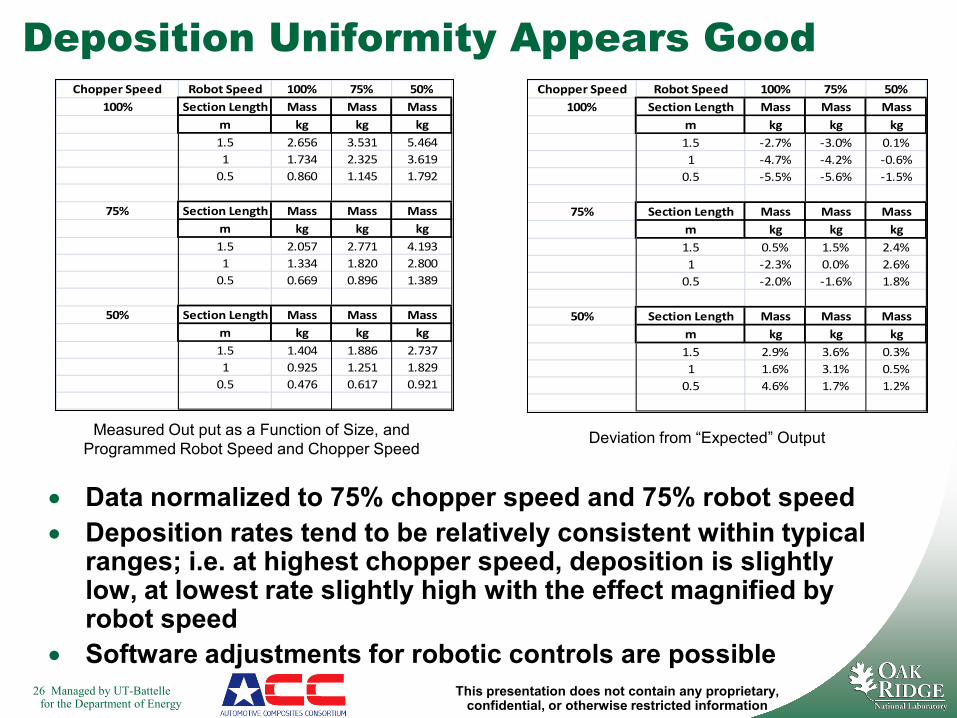
Deposition Uniformity Appears GoodChopper Speed Robot Speed 100% 75% 50%
100% Section Length Mass Mass Massm kg kg kg1.5 2.656 3.531 5.4641 1.734 2.325 3.619
0.5 0.860 1.145 1.792
75% Section Length Mass Mass Massm kg kg kg1.5 2.057 2.771 4.1931 1.334 1.820 2.800
0.5 0.669 0.896 1.389
50% Section Length Mass Mass Massm kg kg kg1.5 1.404 1.886 2.7371 0.925 1.251 1.829
0.5 0.476 0.617 0.921
Chopper Speed Robot Speed 100% 75% 50%100% Section Length Mass Mass Mass
m kg kg kg1.5 -2.7% -3.0% 0.1%1 -4.7% -4.2% -0.6%
0.5 -5.5% -5.6% -1.5%
75% Section Length Mass Mass Massm kg kg kg1.5 0.5% 1.5% 2.4%1 -2.3% 0.0% 2.6%
0.5 -2.0% -1.6% 1.8%
50% Section Length Mass Mass Massm kg kg kg1.5 2.9% 3.6% 0.3%1 1.6% 3.1% 0.5%
0.5 4.6% 1.7% 1.2%
• Data normalized to 75% chopper speed and 75% robot speed• Deposition rates tend to be relatively consistent within typical
ranges; i.e. at highest chopper speed, deposition is slightly low, at lowest rate slightly high with the effect magnified by robot speed
• Software adjustments for robotic controls are possible
Measured Out put as a Function of Size, and Programmed Robot Speed and Chopper Speed
Deviation from “Expected” Output
27 Managed by UT-Battellefor the Department of Energy
This presentation does not contain any proprietary, confidential, or otherwise restricted information
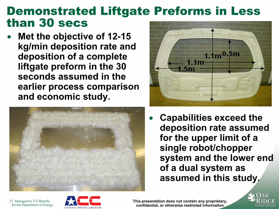
• Capabilities exceed the deposition rate assumed for the upper limit of a single robot/chopper system and the lower end of a dual system as assumed in this study.
Demonstrated Liftgate Preforms in Less than 30 secs• Met the objective of 12-15
kg/min deposition rate and deposition of a complete liftgate preform in the 30 seconds assumed in the earlier process comparison and economic study.
28 Managed by UT-Battellefor the Department of Energy
This presentation does not contain any proprietary, confidential, or otherwise restricted information
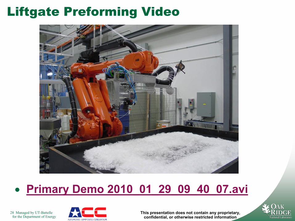
• Primary Demo 2010_01_29_09_40_07.avi
Liftgate Preforming Video
35 Managed by UT-Battellefor the Department of Energy
This presentation does not contain any proprietary, confidential, or otherwise restricted information
• ORNL has been partnering with the ACC and EPFL in developing the technology and demonstrating applicability in high rate thermoplastic preforming for liftgates, seats, etc.
• ORNL has demonstrated some success in utilizing blade coatings developed by C3I for durability improvements
• ORNL has been partnering with Polycomp as potential low cost, high quality “pre-impregnated tow” supplier that might be applicable to preforming and could be added to LCCF line
• ORNL is working informally with Plasticomp and Fiberforge to evaluate related manufacturing technologies for automotive applications
• ORNL has proposed and is exploring partnerships to introduce variants of preforming to wind blade applications and military vehicles to further develop and exploit the technology in other areas to facilitate implementation and drive availability of broader material forms
Advanced Preforming Partnerships
36 Managed by UT-Battellefor the Department of Energy
This presentation does not contain any proprietary, confidential, or otherwise restricted information
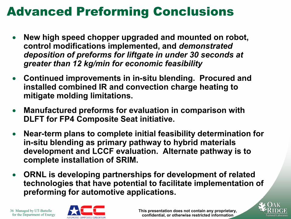
Advanced Preforming Conclusions
• New high speed chopper upgraded and mounted on robot, control modifications implemented, and demonstrated deposition of preforms for liftgate in under 30 seconds at greater than 12 kg/min for economic feasibility
• Continued improvements in in-situ blending. Procured and installed combined IR and convection charge heating to mitigate molding limitations.
• Manufactured preforms for evaluation in comparison with DLFT for FP4 Composite Seat initiative.
• Near-term plans to complete initial feasibility determination for in-situ blending as primary pathway to hybrid materials development and LCCF evaluation. Alternate pathway is to complete installation of SRIM.
• ORNL is developing partnerships for development of related technologies that have potential to facilitate implementation of preforming for automotive applications.
39 Managed by UT-Battellefor the Department of Energy
This presentation does not contain any proprietary, confidential, or otherwise restricted information
Acknowledgements – Lot’s of Key Contributors Have Made an Impact
• ORNL– Ronny Lomax– Ken Yarborough– Fue Xiong– Ray Boeman– Peter Blau– Chris Rouleau– Chris Janke– Don Hutchinson– Bart Smith– Jim Mathys– Rick Battiste– Don Erdman– Srdjan Simunovic– John Allen
(deceased)– Jeanne Phillips– ORNL Craft (too
many to mention)
39
• ORNL (cont)− Roberto
Lenarduzzi− Dave Warren− Phil Sklad
• Suppliers/Other Partners
− Joakim Stridh− Toho/Fortafil
− Zoltec− C3
− Swagelok− Joel Dyksterhouse
− Tim Collins− EPFL
− Fiber Science− Plasticomp− Owens-
CorningVetrotex
• ACC− Jeff Dahl− Glen Smith
− Patrick Blanchard− Stan Iobst
− Libby Berger− Chuck Mentzer
− Jeremy Panasiewicz
− Dan Houston− Ron Cooper− Naponi Rao− Doug Denton− Jim deVries
− Jerry Olszewski
My apologies to those I have left off or whose name I misspelled!
Technical contributors to current/recent activities