Effect of underbody diffuser on the aerodynamic … of underbody diffuser on the aerodynamic drag of...
14
Aulakh, Cogent Engineering (2016), 3: 1230310 http://dx.doi.org/10.1080/23311916.2016.1230310 MECHANICAL ENGINEERING | RESEARCH ARTICLE Effect of underbody diffuser on the aerodynamic drag of vehicles in convoy Deepinder Jot Singh Aulakh 1 * Abstract: Presented work is extension to previous studies of convoying where prime focus was to study effect of intervehicular spacing and upperbody geometry of vehi- cles on aerodynamics of convoy. Current study examines the effect of underbody dif- fuser on coefficient of drag (Cd) of convoy of two reference car bodies (Ahmed body). CFD analysis of convoy is done using Shear-Stress-Transport model under moving ground conditions. The length of lead body’s diffuser is taken as 0.222 m with diffuser angle (degrees) of 0 (no diffuser), 3, 5, 7, 9, 15, 20, 25 and 30 each at intervehicular spacing of 0.25 and 0.75 Ahmed body length. Each configuration thus resulting was analyzed with lead body backlite angle of 25° (pre-critical) and 35° (post-critical) with follow body’s backlite angle remaining 25°. CFD analysis are conducted after perform- ing two validation analyses from previous studies. To understand the flow features developed on Ahmed body due to an underbody diffuser a preliminary analysis is done on an isolated body with 25° and 35° backlite angles by applying each diffuser angle used in current study. After analysis of convoy, drag on lead and follow vehicles is found to be also dependent on the axial vortices formed due to diffuser in addition to those from backlite surface of lead body. Average drag on cases with diffuser is found to be lesser than the no diffuser cases up to a certain diffuser angle. Thus ap- plying diffuser has a potential for reducing the overall drag on convoy. *Corresponding author: Deepinder Jot Singh Aulakh, Department of Mechanical Engineering, Dr. B. R. Ambedkar National Institute of Technology, Jalandhar, Punjab, India E-mail: [email protected] Reviewing editor: Duc Pham, University of Birmingham, UK Additional information is available at the end of the article ABOUT THE AUTHOR Deepinder Jot Singh Aulakh is currently working as quality engineer at Heromotocorp Ltd. He has done his Bachelor of Technology in Mechanical engineering from NIT Jalandhar. His key area of interest is dynamics of road vehicles. His work include design of retractable steering column and variable length wishbones for suspension of off road vehicles and converting 3,100 hp diesel engine to 3,300 hp in a project with Indian railways. Convoying of road vehicles is widely accepted as fuel saving technique by reducing overall aerodynamic drag on vehicles. The research reported in this paper is extension to previous studies on aerodynamics of convoy. Current study explores the effect of installing underbody diffuser to vehicles on overall aerodynamic drag of convoy. The results obtained are quite encouraging as by application of diffuser the overall drag of convoy is further reduced. Thus opening a further prospective of fuel saving. PUBLIC INTEREST STATEMENT As consumption of fuel by road vehicles is increasing, many new techniques are being developed to increase their mileage. Convoying is one of these techniques. In this technique, vehicles traveling on road would assume convoy shapes similar to train carriages and thus will experience lesser air resistance. The lesser the air resistance, the lesser the effort vehicles need to travel (power consumed) and lesser the fuel consumption. Studies done in this area are more concerned with studying the air flow around upper body of a vehicle and finding a suitable distance between convoying vehicles for reducing maximum amount of air resistance. The present study expands this horizon further and studies the flow of air under the body of vehicles travelling in a convoy. This resulted in further possibility of reducing air resistance, thus giving a potential possibility of saving more fuel and money. Received: 18 June 2016 Accepted: 25 August 2016 First Published: 31 August 2016 © 2016 The Author(s). This open access article is distributed under a Creative Commons Attribution (CC-BY) 4.0 license. Page 1 of 14
Transcript of Effect of underbody diffuser on the aerodynamic … of underbody diffuser on the aerodynamic drag of...

Aulakh, Cogent Engineering (2016), 3: 1230310http://dx.doi.org/10.1080/23311916.2016.1230310
MECHANICAL ENGINEERING | RESEARCH ARTICLE
Effect of underbody diffuser on the aerodynamic drag of vehicles in convoyDeepinder Jot Singh Aulakh1*
Abstract: Presented work is extension to previous studies of convoying where prime focus was to study effect of intervehicular spacing and upperbody geometry of vehi-cles on aerodynamics of convoy. Current study examines the effect of underbody dif-fuser on coefficient of drag (Cd) of convoy of two reference car bodies (Ahmed body). CFD analysis of convoy is done using Shear-Stress-Transport model under moving ground conditions. The length of lead body’s diffuser is taken as 0.222 m with diffuser angle (degrees) of 0 (no diffuser), 3, 5, 7, 9, 15, 20, 25 and 30 each at intervehicular spacing of 0.25 and 0.75 Ahmed body length. Each configuration thus resulting was analyzed with lead body backlite angle of 25° (pre-critical) and 35° (post-critical) with follow body’s backlite angle remaining 25°. CFD analysis are conducted after perform-ing two validation analyses from previous studies. To understand the flow features developed on Ahmed body due to an underbody diffuser a preliminary analysis is done on an isolated body with 25° and 35° backlite angles by applying each diffuser angle used in current study. After analysis of convoy, drag on lead and follow vehicles is found to be also dependent on the axial vortices formed due to diffuser in addition to those from backlite surface of lead body. Average drag on cases with diffuser is found to be lesser than the no diffuser cases up to a certain diffuser angle. Thus ap-plying diffuser has a potential for reducing the overall drag on convoy.
*Corresponding author: Deepinder Jot Singh Aulakh, Department of Mechanical Engineering, Dr. B. R. Ambedkar National Institute of Technology, Jalandhar, Punjab, India E-mail: [email protected]
Reviewing editor:Duc Pham, University of Birmingham, UK
Additional information is available at the end of the article
ABOUT THE AUTHORDeepinder Jot Singh Aulakh is currently working as quality engineer at Heromotocorp Ltd. He has done his Bachelor of Technology in Mechanical engineering from NIT Jalandhar. His key area of interest is dynamics of road vehicles. His work include design of retractable steering column and variable length wishbones for suspension of off road vehicles and converting 3,100 hp diesel engine to 3,300 hp in a project with Indian railways.
Convoying of road vehicles is widely accepted as fuel saving technique by reducing overall aerodynamic drag on vehicles. The research reported in this paper is extension to previous studies on aerodynamics of convoy. Current study explores the effect of installing underbody diffuser to vehicles on overall aerodynamic drag of convoy. The results obtained are quite encouraging as by application of diffuser the overall drag of convoy is further reduced. Thus opening a further prospective of fuel saving.
PUBLIC INTEREST STATEMENTAs consumption of fuel by road vehicles is increasing, many new techniques are being developed to increase their mileage. Convoying is one of these techniques. In this technique, vehicles traveling on road would assume convoy shapes similar to train carriages and thus will experience lesser air resistance. The lesser the air resistance, the lesser the effort vehicles need to travel (power consumed) and lesser the fuel consumption. Studies done in this area are more concerned with studying the air flow around upper body of a vehicle and finding a suitable distance between convoying vehicles for reducing maximum amount of air resistance. The present study expands this horizon further and studies the flow of air under the body of vehicles travelling in a convoy. This resulted in further possibility of reducing air resistance, thus giving a potential possibility of saving more fuel and money.
Received: 18 June 2016Accepted: 25 August 2016First Published: 31 August 2016
© 2016 The Author(s). This open access article is distributed under a Creative Commons Attribution (CC-BY) 4.0 license.
Page 1 of 14

Page 2 of 14
Aulakh, Cogent Engineering (2016), 3: 1230310http://dx.doi.org/10.1080/23311916.2016.1230310
Subjects: Aerospace & Aviation Engineering; Aerospace Engineering; Intelligent & Automated Transport System Technology; Mechanical Engineering Design; Transport & Vehicle Engineering
Keywords: coefficient of drag; CFD; underbody diffuser; diffuser angle; backlite angle; Ahmed body; convoy
1. IntroductionIn Automated Highway System (AHS), vehicles travelling on highway assume convoy arrangements, thus experiencing the drag benefits by being closely coupled at high speeds. Vehicles are equipped with Intelligent Transport Systems (ITS) which enable them to travel “safely” close together (less than one car length) (Hall, Thakker, Horan, Glazer, & Hoene, 1997).
There is good amount of study done in the area of convoying as, Zabat, Frascaroli, and Browand (1994) studied the effects of inter-vehicle spacing on aerodynamic drag of vehicles using mini-van geometries and found that significant drag savings were experienced by both lead and trailing model at close proximity, with the lead model benefiting greater and the trailing model benefits with evenly distributed trend over the spacing (Zabat et al., 1994).
Watkins & Vino, 2004 conducted experiments to understand the effects of inter-vehicle spacing using two Ahmed car models with backlite angle of 30°. Significant drag increases were found for the rear Ahmed body at close spacing. It was concluded that the effect of the strong vortex system aris-ing from the slant back of lead body was the cause of the drag and lift changes of the rear vehicle (Watkins & Vino, 2004).
Pagliarella (2009) studied the effects upperbody’s geometry on aerodynamic drag of the convoy of two Ahmed bodies by applying pre-critical (25°) and post critical (35°) backlite angle on the lead body i.e. one configuration with 25° lead and 25° follow vehicle and other with 35° lead and 25° fol-low vehicle. In both cases the trailing model exhibited a rise in drag force above model in isolation values, whilst the leading model exhibited a drag reduction. Net platoon drag was lower than for model in isolation values. Two distinct gap flow phenomena were observed in the intervehicular spacing examined, based on both leading model geometries (Pagliarella, 2009).
As it can be seen from previous studies that most of the literature available in convoying is con-cerned with exploring the effect of either intervehicluar spacing (Watkins & Vino, 2004; Zabat et al., 1994) or upper body geometry of the vehicles in convoy (Pagliarella, 2009). There is no literature available for studying effect of underbody geometry of vehicles on aerodynamics of a convoy. As underbody flows affect the aerodynamics of road vehicles significantly. Current study aims to fill this gap by exploring the effect of underbody diffuser on the aerodynamic drag of vehicles in convoy of a two Ahmed bodies.
2. Reference model and its flow charactersThe most common reference model used by researchers is Ahmed body (Le Good & Garry, 2004). Current study also uses Ahmed body (Figure 1) as reference model as it represents some of the criti-cal flow features (Figure 2) around the vehicle body while maintaining geometrical simplicity (Ahmed, Ramm, & Faltin, 1984). In Ahmed body for backlite angle (ɸ) less than 12.5° flow on it re-mains fully attached and longitudinal vortices (c-pillar) are formed and drag coefficient decreases with increase of the backlite angle. Beyond 12.5° a separating bubble is observed on the backlite surface in addition to strengthened longitudinal vortices. Coefficient of drag increases with increas-ing backlite angle up to angle of 30°. Upon further increasing the backlite angle the flow is com-pletely separated from the backlite surface and longitudinal vortices lose their strength; drag coefficient decreases abruptly (Ahmed et al., 1984).

Page 3 of 14
Aulakh, Cogent Engineering (2016), 3: 1230310http://dx.doi.org/10.1080/23311916.2016.1230310
3. Methodology and scopeThere are many variables in study of this kind; these include vehicle geometric configuration (e.g. truck or car, including fastback, notchback, etc.), intervehicular spacing, number of vehicles in con-voy, configuration of diffuser (length and angle) and the nature and relative direction of the atmos-pheric wind. In order to restrict the number of variables, investigation is limited to CFD simulation of representative car geometry in calm conditions (i.e. no yaw angle) with two Ahmed bodies in a row. Two cases; one with backlite angle 25° in lead body and 25° follow body (25°/25°); while in other case 35° lead and 25° follow body (35°/25°) are chosen in order to study effect of pre and post critical lead body configuration respectively. For above two cases lead body’s underbody diffuser length (ld) is taken as 0.222 m with variable diffuser angle (αd degrees) of 0 (no diffuser), 3, 5, 7, 9, 15, 20, 25 and 30. Underbody diffuser is chosen as only representative of the underbody flow because it is primary component affecting it (Cooper, Bertenyi, Dutil, Syms, & Sovran, 1998). It has also been shown in
Figure 1. Ahmed body (Ahmed et al., 1984).
Figure 2. Proposed vortex system of Ahmed body (Ahmed et al., 1984).

Page 4 of 14
Aulakh, Cogent Engineering (2016), 3: 1230310http://dx.doi.org/10.1080/23311916.2016.1230310
studies that the diffuser angle play important role in the function of diffuser and wake flow struc-tures (Cooper et al., 1998; Fu Limin, 2006). Therefore various angles of diffuser are taken in order to have detail analysis of flow generated by underbody. Every possible configuration resulting from above was tested at intervehicular spacing of 0.25 and 0.75 model length (x/l) with moving ground. As available study on Ahmed body with diffuser is restricted to 35° backlite angle with diffuser an-gles up to 9° (Huminic, Huminic, & Soica, 2012). Therefore to understand the effect of 25° backlite angle and higher diffuser angle a preliminary CFD analysis is done on Ahmed body in isolation. The configurations chosen for this analysis are 25°and 35° backlite angles. Diffuser angles (degrees) are varied as 3, 5, 7, 9, 15, 20, 25 and 30.
The ground condition is taken as moving ground because in static ground conditions the boundary layer developed will affect the results flow in underbody thus give erroneous results for coefficient of drag (Hucho, Janssen, & Schwartz, 1975; Wing, 1981).
4. MeshingThe meshing is done in ANSYS workbench. Mesh is divided into 3 zones. First is inflation zone which first aspect ratio is set as 5 at growth rate of 1.2 (Best practice guidelines for handling Automotive External Aerodynamics with FLUENT, 2016). This is done to properly resolve the boundary layer along the surface of Ahmed body. The second is exterior to first zone; named as body of influence. This is done to fully resolve the flow pattern around the Ahmed body. The outermost zone has relatively coarser mesh for saving computational time. The mesh is shown in Figure 3. This mesh has three bodies of influences as shown in Figure 4. The body I and III have 20 mm as size of element and body II is having 15 mm as size of element. These sizes were decided after conducting grid independence studies. The smaller element size in body II is kept to more accurately resolve the flow region be-tween lead and follow body. The resulting number of elements is 1.1 million for isolated body and 1.5–1.7 million for cases with bodies in tandem.
Figure 3. Different zones of Mesh around Ahmed body.

Page 5 of 14
Aulakh, Cogent Engineering (2016), 3: 1230310http://dx.doi.org/10.1080/23311916.2016.1230310
5. Solver settingsIn this study, the analysis is done with boundary conditions similar to previous study by Huminic et al. (2012) for ease of validation. These boundary conditions are given as velocity of vehicle body relative to air in x direction (Figure 4) is 40 m/s with 0.2% turbulence intensity.
Shear-Stress-Transport (SST) model (Menter, 1994) is used because accuracy of this model has been proved in various previous studies (Huminic & Huminic, 2009, 2010; Huminic et al., 2012). Second order implicit equations for Pressure, Momentum, Turbulence K. E. and Turbulence Dissipation Energy are used.
6. Solver accuracyThe accuracy of SST model for used mesh and solver settings is validated by comparison with previ-ous studies as following:
(1) Comparison with results of study on Ahmed body with diffuser (Huminic et al., 2012).
(2) Comparison] with experimental results for two Ahmed bodies in convoy (Pagliarella, 2009).
6.1. Validation 1The CFD results obtained for Ahmed body (diffuser length ld/l = 0.212) are compared those by Huminic et al. (2012). ld/l = 0.2 case of previous study is chosen for comparison because it is close to value of current study i.e. 0.212. The results are conforming well as shown in Figure 5.
Figure 4. Bodies of influence.
Figure 5. Comparison of Cd value of previous study (Huminic et al., 2012) with CFD results.

Page 6 of 14
Aulakh, Cogent Engineering (2016), 3: 1230310http://dx.doi.org/10.1080/23311916.2016.1230310
6.2. Validation 2In second validation the CFD analysis is done on two Ahmed bodies in convoy in similar arrangement as experimental study of Pagliarella (2009). This analysis is done with static ground conditions be-cause experiements are done on static ground (Pagliarella, 2009). From results obtained the trend is observed to be similar for both CFD and experiments (see Figures 6a and 6b) the slight over predic-tion of the computational values is mainly due to the overestimation of the base pressure drop (Gilliéron & Chometon, 1999).
7. Results
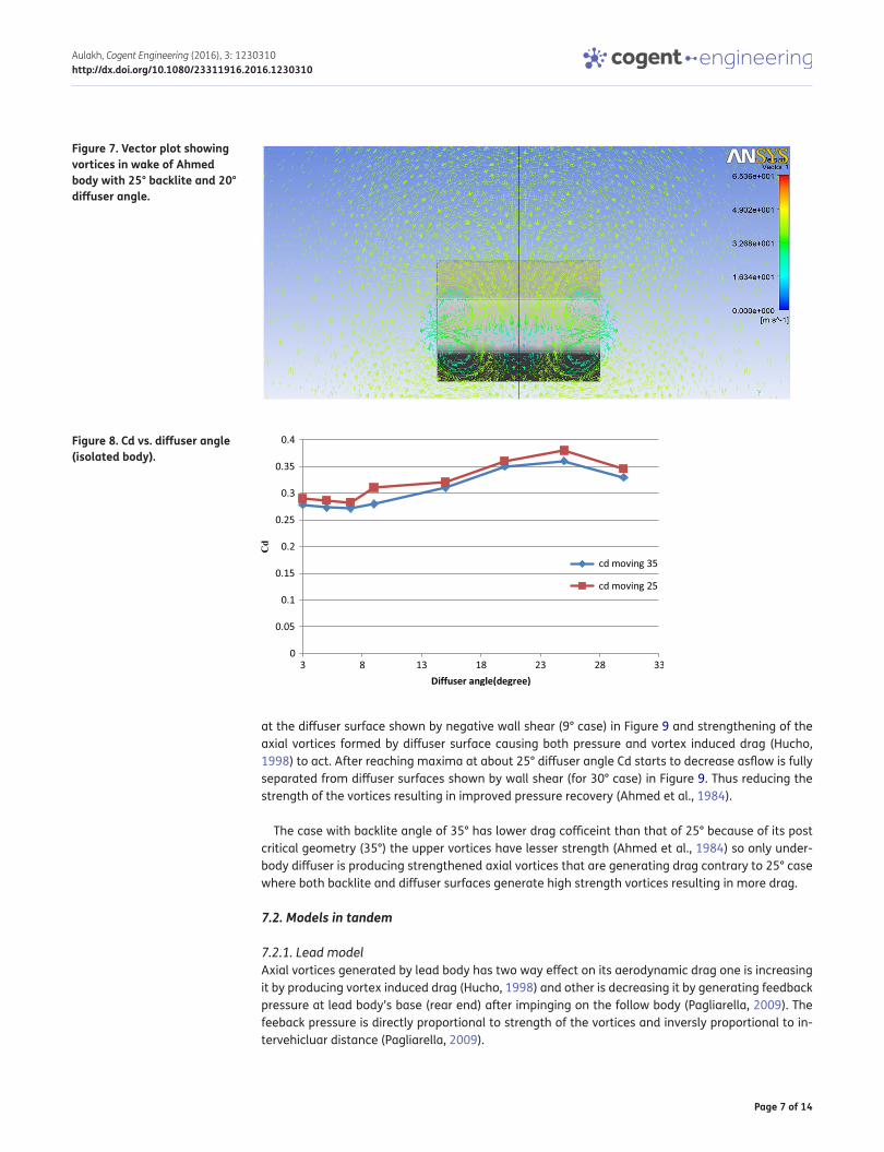
7.1. Model in isolationAs seen from vector plot (Figure 7) in the wake of Ahmed body at a distance of 0.2 m from the rear end of body, four axial vortices are formed two from the upper backlite surface and two from the underbody diffuser surface.
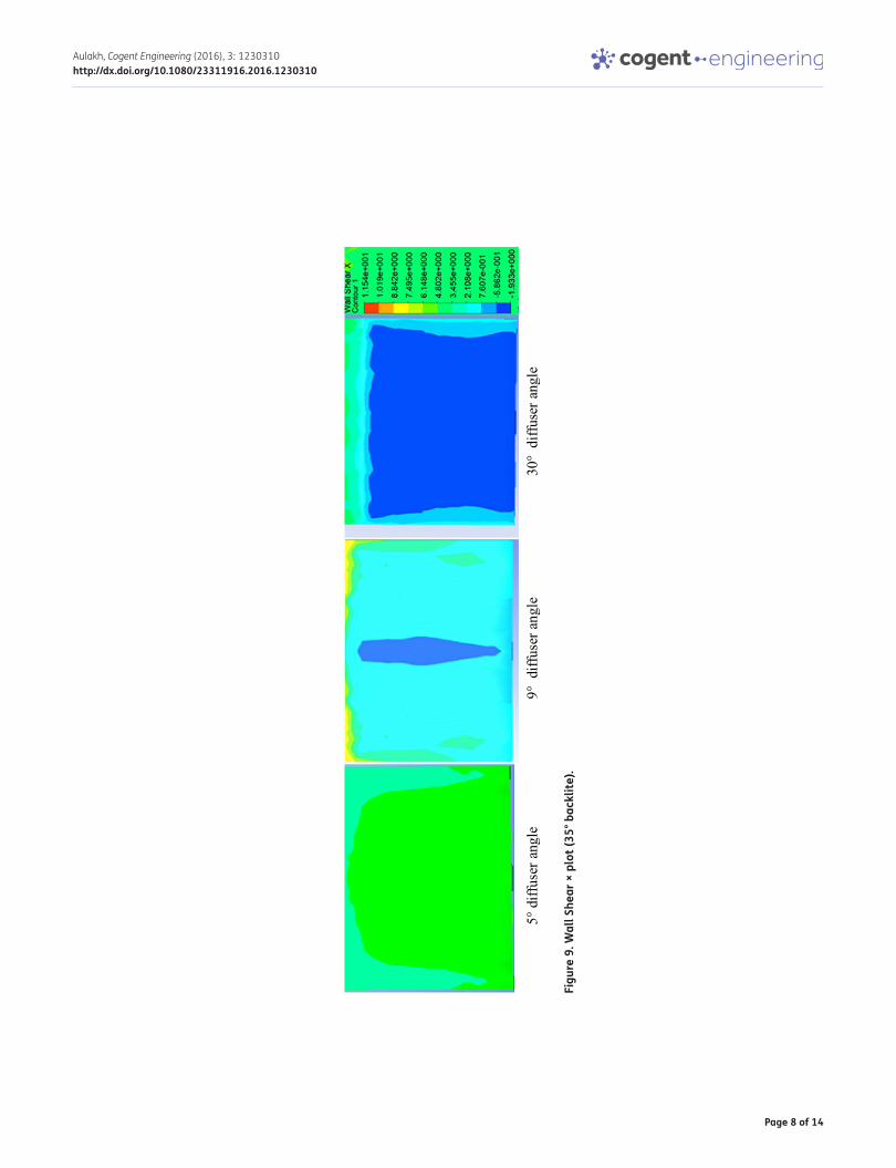
The results for variation of drag coefficient (Cd) are shown in Figure 8. The trend of variation of Cd with diffuser angle is similar in both (25° and 35° backlite) cases. The Cd first decreases up to diffuser angle of 9° and flow is fully attached as shown in wall shear × plot Figure 9 (analogus with regime of Ahmed body up to backlite angle of 12.5° (Ahmed et al., 1984) and l/ld = 0.2 case of previous study (Huminic et al., 2012). After that drag starts to rise this occurs due to formation of separation bubble
Figure 6a. Comparison of Cd (CFD and experimental (Pagliarella, 2009)) at Backlite angle of 25° lead/25° follow model.
Figure 6b. Comparison of Cd (CFD and Exp. (Pagliarella, 2009)) at Backlite angle of 35° lead/25° follow model.
Page 7 of 14
Aulakh, Cogent Engineering (2016), 3: 1230310http://dx.doi.org/10.1080/23311916.2016.1230310
at the diffuser surface shown by negative wall shear (9° case) in Figure 9 and strengthening of the axial vortices formed by diffuser surface causing both pressure and vortex induced drag (Hucho, 1998) to act. After reaching maxima at about 25° diffuser angle Cd starts to decrease asflow is fully separated from diffuser surfaces shown by wall shear (for 30° case) in Figure 9. Thus reducing the strength of the vortices resulting in improved pressure recovery (Ahmed et al., 1984).
The case with backlite angle of 35° has lower drag cofficeint than that of 25° because of its post critical geometry (35°) the upper vortices have lesser strength (Ahmed et al., 1984) so only under-body diffuser is producing strengthened axial vortices that are generating drag contrary to 25° case where both backlite and diffuser surfaces generate high strength vortices resulting in more drag.
7.2. Models in tandem
7.2.1. Lead modelAxial vortices generated by lead body has two way effect on its aerodynamic drag one is increasing it by producing vortex induced drag (Hucho, 1998) and other is decreasing it by generating feedback pressure at lead body’s base (rear end) after impinging on the follow body (Pagliarella, 2009). The feeback pressure is directly proportional to strength of the vortices and inversly proportional to in-tervehicluar distance (Pagliarella, 2009).
Figure 7. Vector plot showing vortices in wake of Ahmed body with 25° backlite and 20° diffuser angle.
Figure 8. Cd vs. diffuser angle (isolated body).
Page 8 of 14
Aulakh, Cogent Engineering (2016), 3: 1230310http://dx.doi.org/10.1080/23311916.2016.1230310
Figu
re 9
. Wal
l She
ar ×
plo
t (35
° bac
klite
).

Page 9 of 14
Aulakh, Cogent Engineering (2016), 3: 1230310http://dx.doi.org/10.1080/23311916.2016.1230310
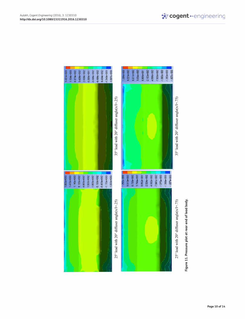
The variation of Cd with diffuser angle is shown in Figure 10. Cd of lead model for each case is lower than isolated values because of feedback pressure developed on the base (rear end) of lead model (Pagliarella, 2009). At intervehicular spacing (x/l) of 0.25 the 25° (backlite angle) lead body has lesser drag cofficeint than 35° lead body this is due to more feedback pressure (Figure 11) arised at base of former caseby two high strength vortices system present (of backlite and diffuser surfac-es)as compared to latter where only one strong vortex system is present (of diffuser).
At x/l of 0.75 effect is opposite i.e. the 25° lead modelhas higher drag than 35° lead model. Because due to incresed spacing in this case the vortices after impinging on follow body are not causing as strong feedback as 0.25 spacing (Pagliarella, 2009). Thus vortex systems have more effect in incres-ing the drag of lead body (as in isolated)than reducing it by feedback leading tolesser pressure at base of 25° lead than 35° lead (Figure 11).
Also from Figure 10, the trend of Cd at x/l = 0.25 is different from that of isolated case i.e. drag decrease with increase in diffuser angle, this is because at closer spacing as feed back mechanism is stronger as compared to phenomenon of vortex induced drag; when the diffuser angle is increased more strong vortices are generated from the underbody and more strong feedback pressure is ap-plied on the base of lead body thus decreasing the drag. This decrease continues till diffuser angle of 25° after that Cd increases because after 25° the separation bubble breaks and flow become fully separated at diffuser surface causing axial vortices to loose their strength in result lesser feed back pressure and more drag.
The trend of Cd variation with diffuser angle for spacing of 0.75 (Figure 10) is similar to that of isoated body. This is due to the larger spacing the feedback mechanism is not as strong. Thus leading to behaviour like isolated body and can be explained similarly. The only difference is of lesser mag-nitude of drag than isolated body this is due to presence of follow body which is still causing some feedback pressure.
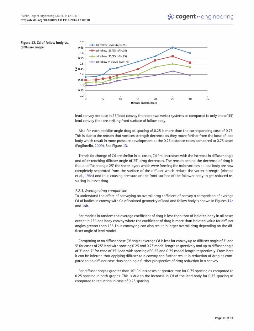
7.2.2. Follow bodyThe follow body has higher Cd than isolated cases. This is due to impingement of axial vortices gen-erated by the lead body which increases the pressure at front surface of the follow body (Pagliarella, 2009). Cd vs. diffuser angle for all cases is shown in Figure 12.
At both intervehicular spacings the follow body with 25° backlite angle lead model convoy has more drag than follow body of 35° lead model convoy. This is due to the more pressure generated (see Figure 13) on the front surface of follow body of 25° lead convoy as compared to follower of 35°
Figure 10. Lead model Cd.
Page 10 of 14
Aulakh, Cogent Engineering (2016), 3: 1230310http://dx.doi.org/10.1080/23311916.2016.1230310
Figu
re 1
1. P
ress
ure
plot
at r
ear e
nd o
f lea
d bo
dy.
Page 11 of 14
Aulakh, Cogent Engineering (2016), 3: 1230310http://dx.doi.org/10.1080/23311916.2016.1230310
lead convoy because in 25° lead convoy there are two vortex systems as compared to only one of 35° lead convoy that are striking front surface of follow body.
Also for each backlite angle drag at spacing of 0.25 is more than the corresponding case of 0.75. This is due to the reason that vortices strength decrease as they move farther from the base of lead body which result in more pressure development at the 0.25 distance cases compared to 0.75 cases (Pagliarella, 2009). See Figure 13.
Trends for change of Cd are similar in all cases, Cd first increases with the increase in diffuser angle and after reaching diffuser angle of 25° drag decreases. The reason behind the decrease of drag is that at diffuser angle 25° the shear layers which were forming the axial vortices at lead body are now completely separated from the surface of the diffuser which reduce the vortex strength (Ahmed et al., 1984) and thus causing pressure on the front surface of the follower body to get reduced re-sulting in lesser drag.
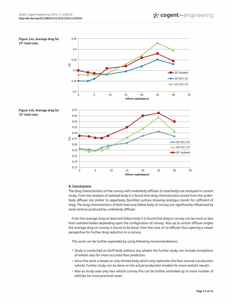
7.2.3. Average drag comparisonTo understand the effect of convoying on overall drag cofficient of convoy a comparison of average Cd of bodies in convoy with Cd of isolated geometry of lead and follow body is shown in Figures 14a and 14b.
For models in tandem the average coefficient of drag is less than that of isolated body in all cases except in 25° lead body convoy where the coefficient of drag is more than isolated value for diffuser angles greater than 13°. Thus convoying can also result in larger overall drag depending on the dif-fuser angle of lead model.
Comparing to no diffuser case (0° angle) average Cd is less for convoy up to diffuser angle of 3° and 5° for cases of 25° lead with spacing 0.25 and 0.75 model length respectively and up to diffuser angle of 3° and 7° for case of 35° lead with spacing of 0.25 and 0.75 model length respectively. From here it can be inferred that applying diffuser to a convoy can further result in reduction of drag as com-pared to no diffuser case thus opening a further prospective of drag reduction in a convoy.
For diffuser angles greater than 10° Cd increases at greater rate for 0.75 spacing as compared to 0.25 spacing in both graphs. This is due to the increase in Cd of the lead body for 0.75 spacing as compared to reduction in case of 0.25 spacing.
Figure 12. Cd of follow body vs. difffuser angle.
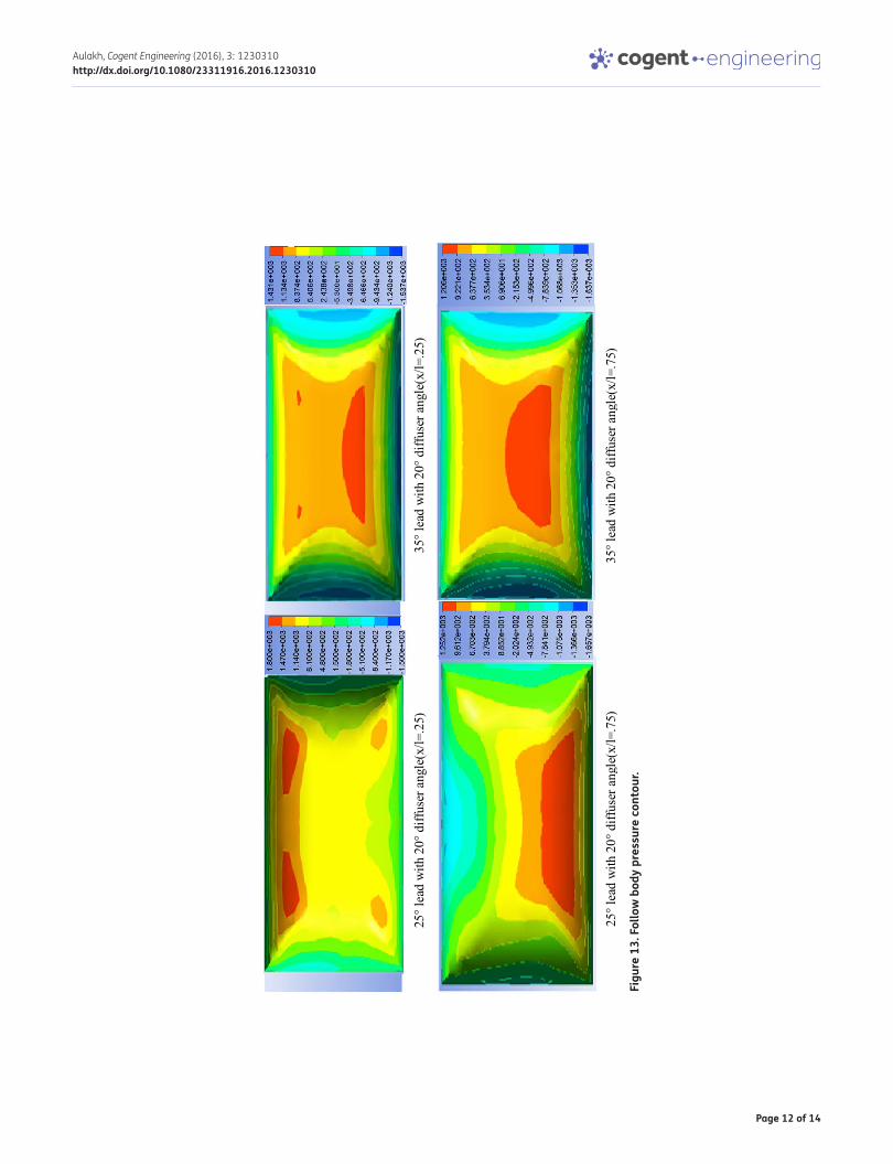
Page 12 of 14
Aulakh, Cogent Engineering (2016), 3: 1230310http://dx.doi.org/10.1080/23311916.2016.1230310
Figu
re 1
3. F
ollo
w b
ody
pres
sure
con
tour
.
Page 13 of 14
Aulakh, Cogent Engineering (2016), 3: 1230310http://dx.doi.org/10.1080/23311916.2016.1230310
8. ConclusionsThe drag characteristics of the convoy with underbody diffuser (in lead body) are analyzed in current study. From the analysis of isolated body it is found that drag charactersitics arised from the under-body diffuser are similar to upperbody (backlite) surface showing analogus trends for cofficient of drag. The drag characteristics of both lead and follow body of convoy are significantly influenced by axial vortices produced by underbody diffuser.
From the average drag on lead and follow body it is found that drag in convoy can be more or less than isolated bodies depending upon the configuration of convoy. Also up to certain diffuser angles the average drag on convoy is found to be lesser than the case of no diffuser thus opening a newer perspective for further drag reduction in a convoy.
This work can be further expanded by using following recommendations:
• Study is conducted on bluff body without any wheels the further study can include simulations of wheels also for more accurate flow prediction.
• Since this work is based on only Ahmed body which only replicates the flow around a production vehicle. Further study can be done on the actual production models for more realistic results.
• Also as study uses only two vehicle convoy this can be further extended up to more number of vehicles for more practical cases.
Figure 14a. Average drag for 25° lead case.
Figure 14b. Average drag for 35° lead case.

Page 14 of 14
Aulakh, Cogent Engineering (2016), 3: 1230310http://dx.doi.org/10.1080/23311916.2016.1230310
© 2016 The Author(s). This open access article is distributed under a Creative Commons Attribution (CC-BY) 4.0 license.You are free to: Share — copy and redistribute the material in any medium or format Adapt — remix, transform, and build upon the material for any purpose, even commercially.The licensor cannot revoke these freedoms as long as you follow the license terms.
Under the following terms:Attribution — You must give appropriate credit, provide a link to the license, and indicate if changes were made. You may do so in any reasonable manner, but not in any way that suggests the licensor endorses you or your use. No additional restrictions You may not apply legal terms or technological measures that legally restrict others from doing anything the license permits.
FundingThe author received no direct funding for this research.
Author detailsDeepinder Jot Singh Aulakh1
E-mail: [email protected] Department of Mechanical Engineering, Dr. B. R. Ambedkar
National Institute of Technology, Jalandhar, Punjab, India.
Citation informationCite this article as: Effect of underbody diffuser on the aerodynamic drag of vehicles in convoy, Deepinder Jot Singh Aulakh, Cogent Engineering (2016), 3: 1230310.
ReferencesAhmed, S., Ramm, G., Faltin, G. (1984). Some salient features
of the time-averaged ground vehicle wake (SAE Technical Paper 840300). doi:10.4271/840300
Best practice guidelines for handling Automotive External Aerodynamics with FLUENT. (2016). Retrieved April 20, 2016, from http://www.southampton.ac.uk/~nwb/lectures/GoodPracticeCFD/Articles/Ext_Aero_Best_Practice_Ver1_2.pdf
Cooper, K., Bertenyi, T., Dutil, G., Syms, J., & Sovran, G. (1998). The aerodynamics performance of automotive underbody diffusers (SAE Technical Paper 980030). doi:10.4271/980030
Fu, L. M. (2006). Automobile aerodynamics. Beijing: China Machinery Press.
Gilliéron, P., & Chometon, F. (1999). Modelling of stationary three-dimensional separated air flows around an Ahmed reference model. ESAIM: Proceedings, 7, 173–182. http://dx.doi.org/10.1051/proc:1999016
Hall, R., Thakker, V., Horan, T., Glazer, J., & Hoene, C. (1997). Automated highway system field operational tests for the state of California: Potential sites, configurations and characteristics (California PATH Research Report UCB-ITSPRR-97-45). ISSN 1055-1425. Berkeley: Institute of transportation studies university of California.
Hucho, W. H. (1998). Aerodynamics of road vehicles (4th ed.). Warrendale, PA: Published by SAE.
Hucho, W. H., Janssen, L. J., & Schwartz, G. (1975). The wind tunnel’s ground plane boundary layer: Its interference with the flow underneath cars (Technical Report 750066). Warrendale, PA: Society of Automotive Engineers.
Huminic, A., & Huminic, G. (2009). CFD study concerning the influence of the underbody components on total drag for a SUV. Vehicle Aerodynamics, SAE SP-2226, 315–321. ISSN 0148-7191. doi:10.4271/2009-01-1157
Huminic, A., & Huminic, G. (2010) Computational study of flow in the underbody diffuser for a simplified car model. Vehicle Aerodynamics, SAE SP 2269, 12–23. ISSN 0148-7191. doi:10.4271/2010-01-0119
Huminic, A., Huminic, G., & Soica, A. (2012). “Study of aerodynamics for a simplified car model with the underbody shaped as a Venturi nozzle. International Journal of Vehicle Dynamics, 58, 15–32.
Le Good, G. M., & Garry, K. P. (2004). On the use of reference models in automotive aerodynamics (SAE 2004-01-1308 also SP-1874). Cranfield: SAE International. ISBN 0-7680-1410-7.
Menter, F. R. (1994). Two-equation eddy-viscosity turbulence models for engineering applications, AIAA Journal, 32, 1598–1605. ISSN 0001-1452. http://dx.doi.org/10.2514/3.12149
Pagliarella, R. M. (2009). On the aerodynamic performance of automotive vehicle platoons featuring pre and post-critical leading forms (Doctoral thesis). Melbourne: School of Aerospace, Mechanical and Manufacturing Engineering, RMIT University.
Watkins, S., & Vino, G. (2004, July). On vehicle spacing and its effect on drag and lift. In Proceedings, Fifth International Colloquium of Bluff Body Aerodynamics & Applications (BBAA5). Ottawa.
Wing, W. (1981). Ground simulation in automotive wind tunnel - a survey (Technical Report WTP 1005). Melbourne: Department of Mechanical and Production Engineering, Royal Melbourne Institute of Technology.
Zabat, M., Frascaroli, S., & Browand, F. (1994). Drag measure-ments on 2, 3 and 4 car platoons (SAE Technical Paper 940421). doi:10.4271/940421