CHECKSHEET FOR PART MINI-PROJECT (Cover page 1 of 2) /24 ...
16
CHECKSHEET FOR PART MINI-PROJECT (Cover page 1 of 2) NAME: _______________ Pre-CAD Plan ___ Identify Primary & Secondary Features ___ Explain Rationale for Location of Origin ___ Pick Effective Front/Top/Side Views ___ Order of Feature Implementation ___ Identify Key Size Dimensions ___ Keep track of ALL Assumptions Above and Beyond (Exemplary) ___ Exceptional organization and neatness ___ Analysis of steps/features that could prove difficult ___Other:____________________________________________________________ Process Documentation ___ Completed Summary and Custom tabs (w/ summary tab overlaid on model) ___ Illustration of Modeling Steps ___ Explanation of Modeling Steps ___ Rationale for Usage of Sketch Tools ___ Expanded and Annotated Design Tree ___ Compelling Lessons Learned (about this part as well as about SolidWorks) Above and Beyond (Exemplary) ___ Exceptional organization and neatness ___ Thoughtful use of Reference or Construction Geometry to Simplify Modeling Other:_______________________________________________________________ Finished Products (based on finished model and drawing) ___ Fully-Defined Sketches ___ Correct/Accurate Model ___ Attractive Visualization of Final Part (include at least 1 color image) ___ Mass properties shown ___ Quality Engineering Drawing(s) on Multiple Sheets (use of part properties, filled out ME template w/ title block items) ___ Complete/Non-redundant dimension scheme Above and Beyond (Exemplary) ___ Effective use of section view, detail view, or other to assist drawing clarity ___ Effective/clean dimension scheme ___ Other:_______________________________________________________________ /8 /8 /8 /24
Transcript of CHECKSHEET FOR PART MINI-PROJECT (Cover page 1 of 2) /24 ...

CHECKSHEET FOR PART MINI-PROJECT (Cover page 1 of 2) NAME: _______________ Pre-CAD Plan
___ Identify Primary & Secondary Features
___ Explain Rationale for Location of Origin
___ Pick Effective Front/Top/Side Views
___ Order of Feature Implementation
___ Identify Key Size Dimensions
___ Keep track of ALL Assumptions
Above and Beyond (Exemplary)
___ Exceptional organization and neatness
___ Analysis of steps/features that could prove difficult
___Other:____________________________________________________________
Process Documentation
___ Completed Summary and Custom tabs (w/ summary tab overlaid on model)
___ Illustration of Modeling Steps
___ Explanation of Modeling Steps
___ Rationale for Usage of Sketch Tools
___ Expanded and Annotated Design Tree
___ Compelling Lessons Learned (about this part as well as about SolidWorks)
Above and Beyond (Exemplary)
___ Exceptional organization and neatness
___ Thoughtful use of Reference or Construction Geometry to Simplify Modeling
Other:_______________________________________________________________
Finished Products (based on finished model and drawing)
___ Fully-Defined Sketches
___ Correct/Accurate Model
___ Attractive Visualization of Final Part (include at least 1 color image)
___ Mass properties shown
___ Quality Engineering Drawing(s) on Multiple Sheets (use of part
properties, filled out ME template w/ title block items)
___ Complete/Non-redundant dimension scheme
Above and Beyond (Exemplary)
___ Effective use of section view, detail view, or other to assist drawing clarity
___ Effective/clean dimension scheme
___
Other:_______________________________________________________________
/8
/8
/8
/24
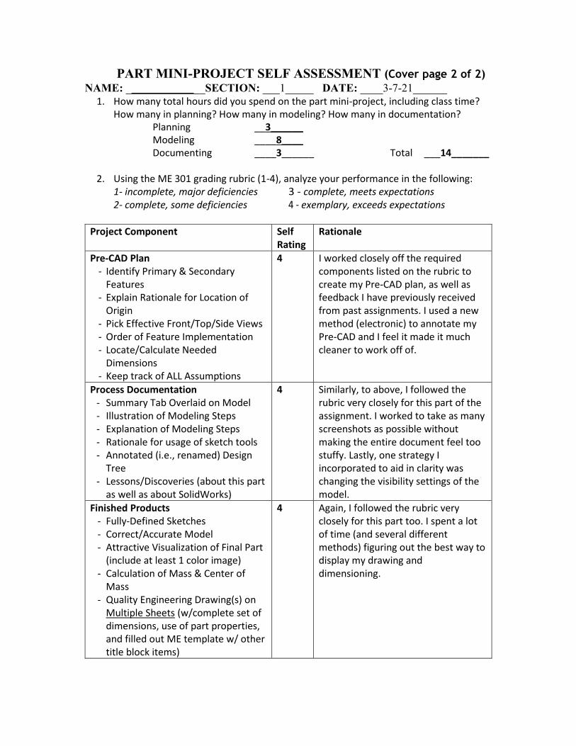
PART MINI-PROJECT SELF ASSESSMENT (Cover page 2 of 2)
NAME: ______________SECTION: ___1_____ DATE: ____3-7-21______
1. How many total hours did you spend on the part mini-project, including class time? How many in planning? How many in modeling? How many in documentation?
Planning __3______ Modeling ____8____ Documenting ____3______ Total ___14_______
2. Using the ME 301 grading rubric (1-4), analyze your performance in the following:
1- incomplete, major deficiencies 3 - complete, meets expectations 2- complete, some deficiencies 4 - exemplary, exceeds expectations
Project Component Self Rating
Rationale
Pre-CAD Plan - Identify Primary & Secondary
Features - Explain Rationale for Location of
Origin - Pick Effective Front/Top/Side Views - Order of Feature Implementation - Locate/Calculate Needed
Dimensions - Keep track of ALL Assumptions
4 I worked closely off the required components listed on the rubric to create my Pre-CAD plan, as well as feedback I have previously received from past assignments. I used a new method (electronic) to annotate my Pre-CAD and I feel it made it much cleaner to work off of.
Process Documentation - Summary Tab Overlaid on Model - Illustration of Modeling Steps - Explanation of Modeling Steps - Rationale for usage of sketch tools - Annotated (i.e., renamed) Design
Tree - Lessons/Discoveries (about this part
as well as about SolidWorks)
4 Similarly, to above, I followed the rubric very closely for this part of the assignment. I worked to take as many screenshots as possible without making the entire document feel too stuffy. Lastly, one strategy I incorporated to aid in clarity was changing the visibility settings of the model.
Finished Products - Fully-Defined Sketches - Correct/Accurate Model - Attractive Visualization of Final Part
(include at least 1 color image) - Calculation of Mass & Center of
Mass - Quality Engineering Drawing(s) on
Multiple Sheets (w/complete set of dimensions, use of part properties, and filled out ME template w/ other title block items)
4 Again, I followed the rubric very closely for this part too. I spent a lot of time (and several different methods) figuring out the best way to display my drawing and dimensioning.

1
.
2
.
3a
.
3
. 5
.
2a
.
3b
.
Z
Y 4.
1a
.
X
Y
4.

Note: Highlighted Dimensions are “key dimensions” for creating the sketches and features
1. (Primary Feature) Sketch the structural geometry of the fly wheel on the Right Plane using dimensions
and relations from 1a. Revolve the sketch around a centerline running through Origin (placed in the center
of the component to allow for concentric circles constrained to Origin in step 4).
2. (Secondary Feature) Sketch a “seed” fin on the Front Plane. Dimension according to 2a. Sketch will be
defined off the origin and walls. Extrude up to next surface will be used to finish the seed geometry.
3. Use Hole Wizard to create seed holes for hole 3a and 3b¸ considering they are two different sizes.
Assume 3b is a tapped screw hole. 4. (Secondary Feature) Use a Circular Pattern around the highlighted pattern on Front Plane to create the
14 fins, 6 3b holes, and 2 3a holes. Bodies will be merged.
5. (Secondary Feature) Create a Lofted Cut through the inner keyhole to remove the material for the notch.
Two planes will be made (dashed orange) based off the Front Plane. They will have two offset rectangles
that I will loft cut between.
Assumptions:
- there are 6 3b holes but only 2 x 3a holes (based off annotations).
- Extruding “Up to next surface” will work when the terminating face is curved.
- The fins are indeed filler material between the outer and inner casing, and an extrusion up to the surface
will create the correct fin depth
- The hole sizes are M7 and 20 mm
Pre-CAD Plan:
Lessons Learned:
1. This was the first part we have had to model that I found the most challenging part was the initial sketches.
I think this was due to a few reasons, but notably I found that sketching the curves and arcs were very hard
to fully define and lock into place. After spending a while messing around and trying different techniques,
I finally began to realize that the tangent relation is very powerful because it can lock in and align both an
arc and a line simultaneously.
2. I have found that one of the most valuable aspects of creating a part occurs with the Pre-CAD plan. Taking
the time to plan out and consider what features and the order to create the part helped make it a smooth
part to begin modelling. Additionally, at the times when I became challenged, having a prepared and
organized Pre-CAD plan made it easy to explain to the mentors or my peers the exact step I am stuck on –
and in the end, this expedites the entire sketching process.
3. Another very important skill that I feel I have begun to master from this part was the function and
implementation of section views within my Part Drawing. It would have been impossible to fully
dimension this sketch in the drawing without cutting away part materials to view the central bore and fins.
However, in the beginning I found it challenging to select the correct view to cut-away. Later, I realized
that the section views cut away material perpendicular to the “section line”. Similarly, using the detailed
view to clearly focus upon the central bore (my first sketch) made my entire drawing many times cleaner
and more legible. In the future I will definitely work to incorporate these views types into future
assignment drawings.
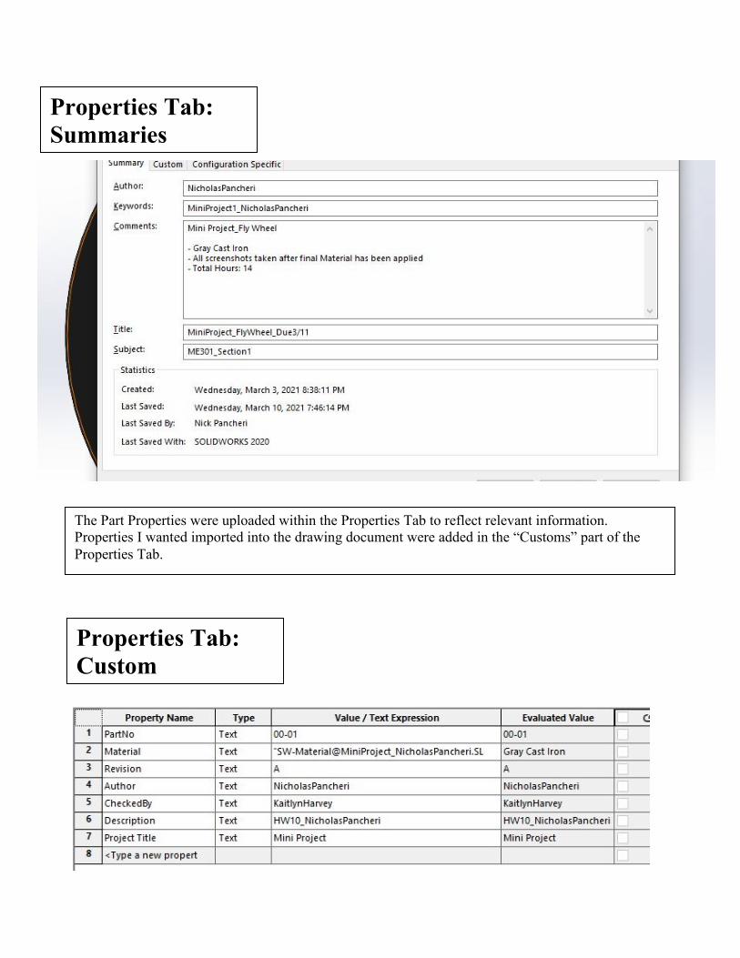
Properties Tab:
Summaries
Properties Tab:
Custom
The Part Properties were uploaded within the Properties Tab to reflect relevant information.
Properties I wanted imported into the drawing document were added in the “Customs” part of the
Properties Tab.

Design Tree:
Each Feature and Sketch (except for
Reference planes because they were
so numerous and multi-use) was given
a descriptive name.
Mass Properties:
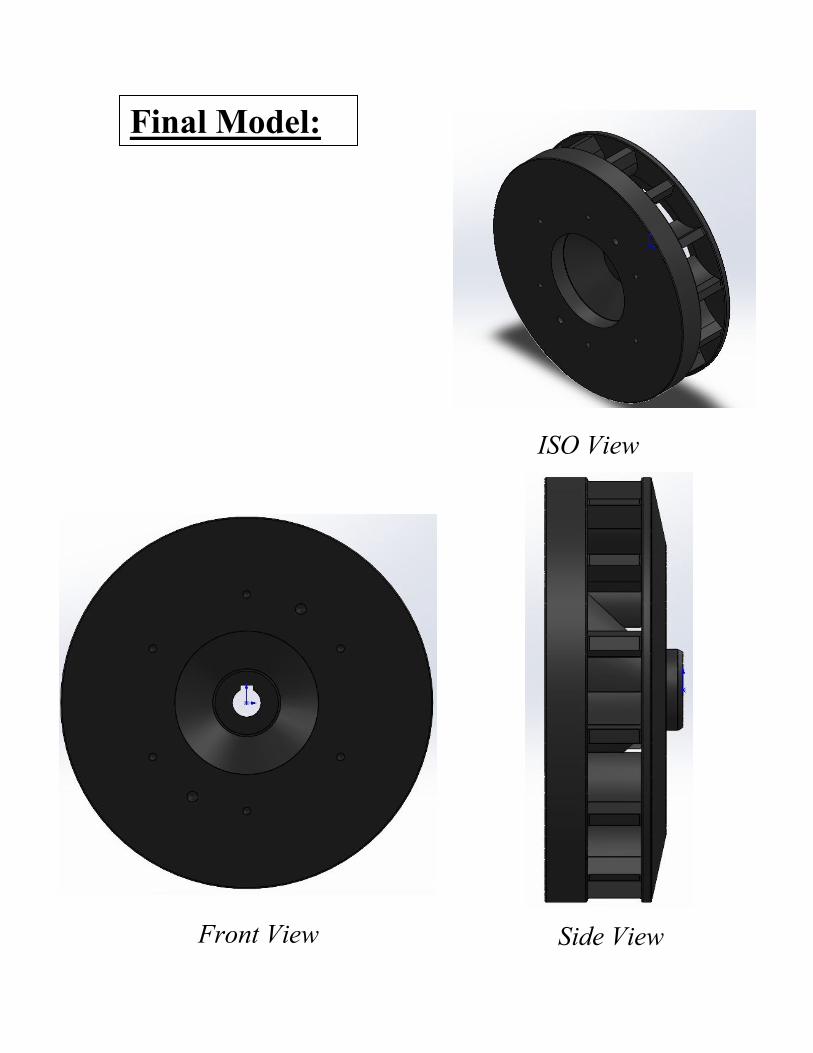
Final Model:
Front View
ISO View
Side View

1. Sketch for Revolve
I began by creating a sketch profile on the Top
Plane using the dimensions provided by the
original schematic. Notably, I set my origin on
the centerline of the revolve, which allowed
for dimensioning scheme to use diameters just
like the schematic. The most challenging piece
to sketch was the 12 mm radius that connects
to the neck between the upper and lower parts.
I tried using both the arc tool and feature fillet
afterwards, but neither worked properly.
Finally, I created a 12 mm radius circle and
used tangent relations to join it together. That
worked perfectly. It was conceptually
confusing to sketch the lower right component
that was free floating from the rest of the
geometry.
2. Revolving the Sketch
I then used the Revolve Feature to
create a Parent Feature. At this
point, it was two separate bodies
within the sketch. I specifically
chose this feature because it was by
far the simplest, most efficient way
to model the part, especially
compared to lofting or extruding it.
Note: All my snips are taken after finishing the part (they are all taken with Gray Cast Iron as the
material) using the rollback bar. Also, my part Visibility varies throughout the documentation
Depending on how it effects the ability to see new Features and Sketches.

4. Adding Clearance for the 6 x
M7 Holes
In order to add the 2 mm clearance
hole that each of the 6 M7 holes sits
in, I first created a 170 mm
Reference Bolt Circle. I then
sketched a circle on this reference
circle and made it Vertically
Related to the origin. I used a Cut
Extrude to create the 2 mm
Secondary Feature that the M7
holes would later be nestled in. I
made an Assumption that the
clearance hole was the same
diameter as the hole feature it would
contain.
3. Sketching the Seed Fin
I began a sketch of the fin on the interior
face of the revolved Parent Feature. To
define the sketch, I had to create a
reference circle of 192 mm diameter to
make the tip of the fin coincident with. I
also made a centerline running from the
origin vertically up to the center of the fin
and added a vertical relation. The
challenging part of this sketch was correctly
adding in the curved arcs. After trying a
few different things, I finally made both
arcs (R32 and R50) tangent to a centered,
10 mm wide rectangle. I then used the
Power Trim tool to remove excess lines
and close the sketch geometry.
I Extruded this fine with the Up to
Surface end condition to span the gap
between the bodies from my Revolve
Sketch. I made sure to selected Merge
Bodies, resulting in one single, merged
body within my part.

`
5. Hole Wizard 1: 6 x M7 Holes
I then used the Hole Wizard to create another
Secondary Feature within clearance hole I
made in Step 5 (above). I assumed a
Straight Tap w/ the Bottoming Tapped
Hole type. I used an M7 hole as specified in
the schematic.
6. Circular Patterning Fins and M7 Holes
At this point, I created two Circular Pattern
Features based off my Seed Fin Sketch
(Step 3 ) and Clearance Hole/Hole Wizard
Sketches (Steps 4 & 5). For both patterns, I
used the outer edges of the part (highlighted
Orange) as my Direction 1. I repeated the
Fins 14 times and Both holes 6 times. I
specifically chose to use this feature because
it is the most efficient and accurate way to
create these equally spaced components of the
part.

8. Hole Wizard 2:
Then, I added second hole type,
assuming it is a Straight Tap w/
the Tapped Hole type. I did have a
tough time fully define the
placement of the hole. I ended up
creating conjoining line segments
from between two holes of 7m
Circular Hole Pattern and added a
Midpoint Relation and made it
Concentric with my original
Reference Bolt Circle. I assumed it
was a 20 mm depth based off the
schematic.
7. Circular Patterning M10 Holes
I completed the Hole Features by adding the
second M10 hole by creating a third Circular
Pattern Feature. I made it to occur 2 times,
using the inner rim (highlighted Orange) as
Direction 1.

9. Lofting the Keyhole
To add the keyhole running through the central bore, I made a Central
Reference Plane based off the Front Plane (Above Left). I sketched
two rectangles on each plane that were Horizontally and Vertically
Related to the front and back perimeters, respectively, of the central
bore (Above Right). I then used the Lofted Cut Feature to remove the
material and create the keyhole geometry. I specifically used the Lofted
Cut Feature because it allowed me to create two similar rectangles based
on whatever reference geometry I desired.
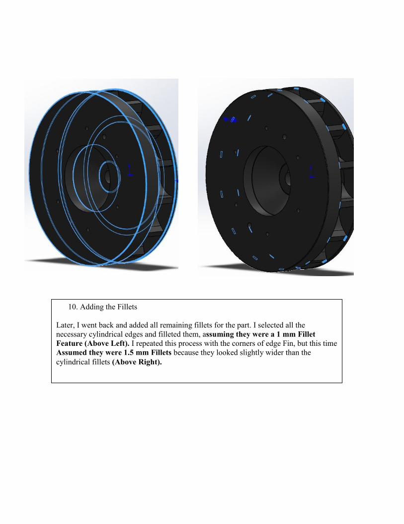
10. Adding the Fillets
Later, I went back and added all remaining fillets for the part. I selected all the
necessary cylindrical edges and filleted them, assuming they were a 1 mm Fillet
Feature (Above Left). I repeated this process with the corners of edge Fin, but this time
Assumed they were 1.5 mm Fillets because they looked slightly wider than the
cylindrical fillets (Above Right).
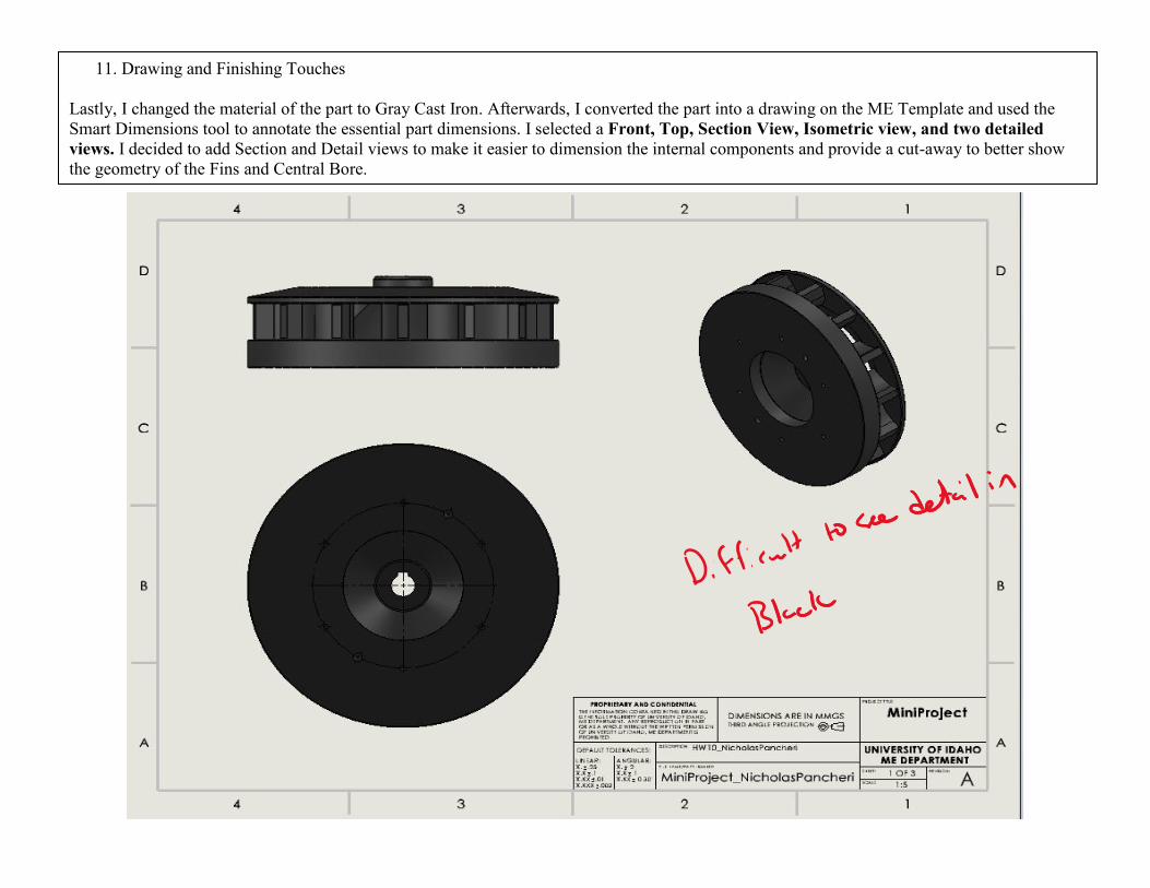
11. Drawing and Finishing Touches
Lastly, I changed the material of the part to Gray Cast Iron. Afterwards, I converted the part into a drawing on the ME Template and used the
Smart Dimensions tool to annotate the essential part dimensions. I selected a Front, Top, Section View, Isometric view, and two detailed
views. I decided to add Section and Detail views to make it easier to dimension the internal components and provide a cut-away to better show
the geometry of the Fins and Central Bore.