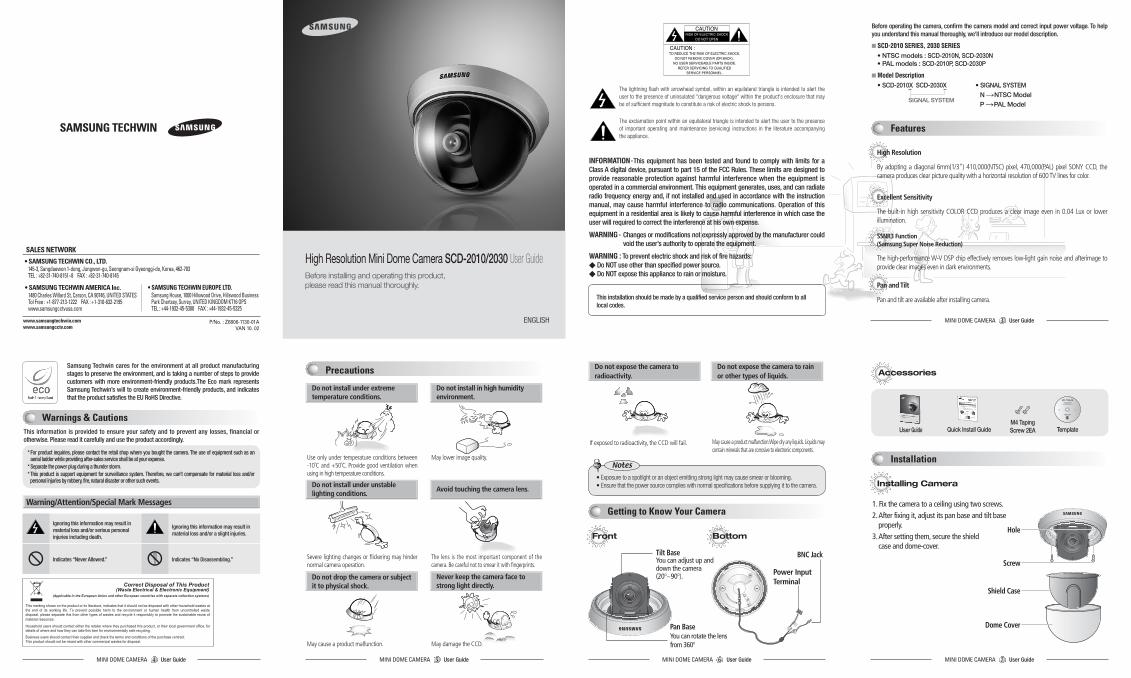
High Resolution Mini Dome Camera SCD-2010/2030 User …€¦ · High Resolution Mini Dome Camera...
2
P/No. : Z6806-1130-01A VAN 10. 02 www.samsungtechwin.com www.samsungcctv.com • SAMSUNG TECHWIN CO., LTD. 145-3, Sangdaewon 1-dong, Jungwon-gu, Seongnam-si Gyeonggi-do, Korea, 462-703 TEL : +82-31-740-8151~8 FAX : +82-31-740-8145 • SAMSUNG TECHWIN EUROPE LTD. Samsung House, 1000 Hillswood Drive, Hillswood Business Park Chertsey, Surrey, UNITED KINGDOM KT16 OPS TEL : +44-1932-45-5300 FAX : +44-1932-45-5325 • SAMSUNG TECHWIN AMERICA Inc. 1480 Charles Willard St, Carson, CA 90746, UNITED STATES Tol Free : +1-877-213-1222 FAX : +1-310-632-2195 www.samsungcctvusa.com SALES NETWORK Before installing and operating this product, please read this manual thoroughly. High Resolution Mini Dome Camera SCD-2010/2030 User Guide ENGLISH Samsung Techwin cares for the environment at all product manufacturing stages to preserve the environment, and is taking a number of steps to provide customers with more environment-friendly products.The Eco mark represents Samsung Techwin’s will to create environment-friendly products, and indicates that the product satisfies the EU RoHS Directive. This installation should be made by a qualified service person and should conform to all local codes. The lightning flash with arrowhead symbol, within an equilateral triangle is intended to alert the user to the presence of uninsulated "dangerous voltage" within the product's enclosure that may be of sufficient magnitude to constitute a risk of electric shock to persons. The exclamation point within an equilateral triangle is intended to alert the user to the presence of important operating and maintenance (servicing) instructions in the literature accompanying the appliance. INFORMATION-This equipment has been tested and found to comply with limits for a Class A digital device, pursuant to part 15 of the FCC Rules. These limits are designed to provide reasonable protection against harmful interference when the equipment is operated in a commercial environment. This equipment generates, uses, and can radiate radio frequency energy and, if not installed and used in accordance with the instruction manual, may cause harmful interference to radio communications. Operation of this equipment in a residential area is likely to cause harmful interference in which case the user will required to correct the interference at his own expense. WARNING - Changes or modifications not expressly approved by the manufacturer could void the user’s authority to operate the equipment. WARNING : To prevent electric shock and risk of fire hazards: ◆ Do NOT use other than specified power source. ◆ Do NOT expose this appliance to rain or moisture. High Resolution By adopting a diagonal 6mm(1/3") 410,000(NTSC) pixel, 470,000(PAL) pixel SONY CCD, the camera produces clear picture quality with a horizontal resolution of 600 TV lines for color. Excellent Sensitivity The built-in high sensitivity COLOR CCD produces a clear image even in 0.04 Lux or lower illumination. SSNR3 Function (Samsung Super Noise Reduction) The high-performance W-V DSP chip effectively removes low-light gain noise and afterimage to provide clear images even in dark environments. Pan and Tilt Pan and tilt are available after installing camera. Before operating the camera, confirm the camera model and correct input power voltage. To help you understand this manual thoroughly, we'll introduce our model description. ◾ SCD-2010 SERIES, 2030 SERIES • NTSC models : SCD-2010N, SCD-2030N • PAL models : SCD-2010P, SCD-2030P ◾ Model Description • SCD-2010X SCD-2030X • SIGNAL SYSTEM This information is provided to ensure your safety and to prevent any losses, financial or otherwise. Please read it carefully and use the product accordingly. * For product inquiries, please contact the retail shop where you bought the camera. The use of equipment such as an aerial ladder while providing after-sales service shall be at your expense. * Separate the power plug during a thunder storm. * This product is support equipment for surveillance system. Therefore, we can't compensate for material loss and/or personal injuries by robbery, fire, natural disaster or other such events. Ignoring this information may result in material loss and/or serious personal injuries including death. Indicates “Never Allowed.” Ignoring this information may result in material loss and/or a slight injuries. Indicates “No Disassembling.” Warning/Attention/Special Mark Messages Pan Base You can rotate the lens from 360º Tilt Base You can adjust up and down the camera (20º~90º). BNC Jack Power Input Terminal Front Bottom Do not install under extreme temperature conditions. Use only under temperature conditions between -10˚C and +50˚C. Provide good ventilation when using in high temperature conditions. Do not expose the camera to radioactivity. Do not expose the camera to rain or other types of liquids. If exposed to radioactivity, the CCD will fail. May cause a product malfunction.Wipe dry any liquids. Liquids may contain minerals that are corrosive to electronic components. Do not install in high humidity environment. May lower image quality. Do not install under unstable lighting conditions. Severe lighting changes or flickering may hinder normal camera operation. Avoid touching the camera lens. The lens is the most important component of the camera. Be careful not to smear it with fingerprints. Do not drop the camera or subject it to physical shock. May cause a product malfunction. May damage the CCD. Never keep the camera face to strong light directly. Accessories User Guide Quick Install Guide M4 Taping Screw 2EA Template Installing Camera 1. Fix the camera to a ceiling using two screws. 2. After fixing it, adjust its pan base and tilt base properly. 3. After setting them, secure the shield case and dome-cover. Screw Shield Case Dome Cover Hole Features Precautions Getting to Know Your Camera Installation Warnings & Cautions MINI DOME CAMERA User Guide 7 MINI DOME CAMERA User Guide 3 MINI DOME CAMERA User Guide 6 MINI DOME CAMERA User Guide 5 MINI DOME CAMERA User Guide 4 N →NTSC Model P →PAL Model SIGNAL SYSTEM • Exposuretoaspotlightoranobjectemittingstronglightmaycausesmearorblooming. • Ensurethatthepowersourcecomplieswithnormalspecificationsbeforesupplyingittothecamera. Notes
Transcript of High Resolution Mini Dome Camera SCD-2010/2030 User …€¦ · High Resolution Mini Dome Camera...
P/No. : Z6806-1130-01A VAN 10. 02
www.samsungtechwin.comwww.samsungcctv.com
• SAMSUNG TECHWIN CO., LTD.145-3, Sangdaewon 1-dong, Jungwon-gu, Seongnam-si Gyeonggi-do, Korea, 462-703 TEL : +82-31-740-8151~8 FAX : +82-31-740-8145
• SAMSUNG TECHWIN EUROPE LTD. Samsung House, 1000 Hillswood Drive, Hillswood Business Park Chertsey, Surrey, UNITED KINGDOM KT16 OPSTEL : +44-1932-45-5300 FAX : +44-1932-45-5325
• SAMSUNG TECHWIN AMERICA Inc.1480 Charles Willard St, Carson, CA 90746, UNITED STATESTol Free : +1-877-213-1222 FAX : +1-310-632-2195 www.samsungcctvusa.com
SALES NETWORK
MINI DOME CAMERA USERユS MANUAL1
Before installing and operating this product, please read this manual thoroughly.
High Resolution Mini Dome Camera SCD-2010/2030 User Guide
ENGLISH
Samsung Techwin cares for the environment at all product manufacturing stages to preserve the environment, and is taking a number of steps to provide customers with more environment-friendly products.The Eco mark represents Samsung Techwin’s will to create environment-friendly products, and indicates that the product satisfies the EU RoHS Directive.
This installation should be made by a qualified service person and should conform to all local codes.
The lightning flash with arrowhead symbol, within an equilateral triangle is intended to alert the user to the presence of uninsulated "dangerous voltage" within the product's enclosure that may be of sufficient magnitude to constitute a risk of electric shock to persons.
The exclamation point within an equilateral triangle is intended to alert the user to the presence of important operating and maintenance (servicing) instructions in the literature accompanying the appliance.
INFORMATION-This equipment has been tested and found to comply with limits for a Class A digital device, pursuant to part 15 of the FCC Rules. These limits are designed to provide reasonable protection against harmful interference when the equipment is operated in a commercial environment. This equipment generates, uses, and can radiate radio frequency energy and, if not installed and used in accordance with the instruction manual, may cause harmful interference to radio communications. Operation of this equipment in a residential area is likely to cause harmful interference in which case the user will required to correct the interference at his own expense.
WARNING- Changes or modifications not expressly approved by the manufacturer could void the user’s authority to operate the equipment.
WARNING : To prevent electric shock and risk of fire hazards: Do NOT use other than specified power source. Do NOT expose this appliance to rain or moisture.
High Resolution
By adopting a diagonal 6mm(1/3") 410,000(NTSC) pixel, 470,000(PAL) pixel SONY CCD, the camera produces clear picture quality with a horizontal resolution of 600 TV lines for color.
Excellent Sensitivity
The built-in high sensitivity COLOR CCD produces a clear image even in 0.04 Lux or lower illumination.
SSNR3 Function(Samsung Super Noise Reduction)
The high-performance W-V DSP chip effectively removes low-light gain noise and afterimage to provide clear images even in dark environments.
Pan and Tilt
Pan and tilt are available after installing camera.
Before operating the camera, confirm the camera model and correct input power voltage. To help you understand this manual thoroughly, we'll introduce our model description.
◾ SCD-2010 SERIES, 2030 SERIES • NTSC models : SCD-2010N, SCD-2030N • PAL models : SCD-2010P, SCD-2030P
◾ Model Description• SCD-2010X SCD-2030X • SIGNAL SYSTEM
This information is provided to ensure your safety and to prevent any losses, financial or otherwise. Please read it carefully and use the product accordingly.
* For product inquiries, please contact the retail shop where you bought the camera. The use of equipment such as an aerial ladder while providing after-sales service shall be at your expense.
* Separate the power plug during a thunder storm. * This product is support equipment for surveillance system. Therefore, we can't compensate for material loss and/or
personal injuries by robbery, fire, natural disaster or other such events.
Ignoring this information may result in material loss and/or serious personal injuries including death.
Indicates “Never Allowed.”
Ignoring this information may result in material loss and/or a slight injuries.
Indicates “No Disassembling.”
Warning/Attention/Special Mark Messages
Pan BaseYou can rotate the lens from 360º
Tilt Base You can adjust up and down the camera(20º~90º).
BNC Jack
Power Input Terminal
Front Bottom
Do not install under extreme temperature conditions.
Use only under temperature conditions between -10˚C and +50˚C. Provide good ventilation when using in high temperature conditions.
Do not expose the camera to radioactivity.
Do not expose the camera to rainor other types of liquids.
If exposed to radioactivity, the CCD will fail. May cause a product malfunction.Wipe dry any liquids. Liquids may contain minerals that are corrosive to electronic components.
Do not install in high humidity environment.
May lower image quality.
Do not install under unstable lighting conditions.
Severe lighting changes or flickering may hinder normal camera operation.
Avoid touching the camera lens.
The lens is the most important component of the camera. Be careful not to smear it with fingerprints.
Do not drop the camera or subject it to physical shock.
May cause a product malfunction. May damage the CCD.
Never keep the camera face to strong light directly.
Accessories
User Guide Quick Install GuideM4 Taping Screw 2EA Template
Installing Camera
1. Fix the camera to a ceiling using two screws.2. After fixing it, adjust its pan base and tilt base
properly.3. After setting them, secure the shield
case and dome-cover.
Screw
Shield Case
Dome Cover
Hole
Features
Precautions
Getting to Know Your Camera
Installation
Warnings & Cautions
MINI DOME CAMERA User Guide7
MINI DOME CAMERA User Guide3
MINI DOME CAMERA User Guide 6MINI DOME CAMERA User Guide5MINI DOME CAMERA User Guide4
N →NTSC Model P →PAL Model
SIGNAL SYSTEM
•Exposuretoaspotlightoranobjectemittingstronglightmaycausesmearorblooming.•Ensurethatthepowersourcecomplieswithnormalspecificationsbeforesupplyingittothecamera.
Notes

MINI DOME CAMERA User Guide12 MINI DOME CAMERA User Guide13 MINI DOME CAMERA User Guide14 MINI DOME CAMERA User Guide15
MINI DOME CAMERA User Guide11MINI DOME CAMERA User Guide10MINI DOME CAMERA User Guide9MINI DOME CAMERA User Guide8
•When installing the camera on a ceiling not to disturb adjustment ofTilt Base angle fix theBNC-PowerCableonthePanBaseclip.
Notes
Connecting to Power
• Connect the adapter to the power input connector as shown in the figure below. Use a DC 12V. (The Adapter is not provided with the Dome Camera.)
DOMECamera
Adapter(notprovided)
PowerInputConnector
DOMECamera
BNC-Power Cable Pan Base Clip
Connection to Monitor
• As a connecting method varies according to instruments, refer to the manual supplied with the instrument.
• Connect the cable after power is turned off.
Resistance of copper wire [at 20Cº(68ºF)]
• As the voltage drop according to the length of the cable in the above table, a camera may malfunction if there is an excessively long cable run.* Voltage for camera operation: 12V DC ±10%* Voltage drops in the above table are variable according to types of cable manufacturer.
For DC Power Type
Connect the VIDEO-OUT jack to the VIDEO-IN jack of monitor.
•AfterlooseningPanorTiltBaseholdingscrews,adjustitsangle.Andthentightenscrewsagain.•Incaseofadjustingthetilting,donottakethelensforpreventinghysicalshocks.PleasetaketheTiltBase.•Thisdomecameraistobeinstalledontheceilingbyfactorydefault.
Notes
Panning & Tilting Control
You can adjust the Panning and Tilting angle freely. (Panning angle: 360º, Tilting angle: 20º~90º)
1) Adjustment Panning angle: After attaching the dome camera to a ceiling, adjust the panning angle for better monitoring area by rotating the Pan Base. The panning angle can be adjusted 360º freely.
2) Adjustment Tilting angle: After attaching the dome camera to a ceiling, adjust the tilting angle for better monitoring area by rotating the Tilt Base. The tilting angle can be adjusted to 20º from 90º freely. (based the ceiling surface)
Pan BaseYou can rotate the lens from 360
Tilt Base Holding Screws
Tilt BaseYou can adjust up and down
the camera (20º~90º).
Pan Base Holding Screw
If you have trouble operating your camera, refer to the following. If the guidelines do not enable you to solve the problem, contact an authorized technician.◾ The image on the screen is dim. •Checkifthelensarestained.Ifdirty,cleanthelenswithsoft,cleancloth. •The image is dimmer at night than daytime. If the focus is not right, adjust it at daytime.◾ The contrast on the screen is too weak. •Adjustthecontrastfeatureofthemonitor. •Ifthecameraisexposedundertoostronglight,changethecameraposition. •AdjustthelensBACKFOCUSagain.◾ The camera is not work properly, and the surface of the camera case is hot.•Checkthatyouhaveconnectedthecameratoaproperpower(DC12V).
Application of Council Directive(s) 2004 / 108 / EC
Manufacturer's Name SAMSUNG TECHWIN CO., LTD
Manufacturer's Address SAMSUNG TECHWIN CO., LTD
42, SUNGJU-DONG CHANGWON-CITY,
KYUNGNAM, KOREA, 641-120
European Representative Name
European Representative Address
Equipment Type/Environment MINI DOME CAMERA
Model Name SCD-2010/2030
Beginning Serial NO. C53C6V3Z200001X, C58I6V3Z200001X
Year of Manufacture 2010.02.01
Conformance to EN 55022 : 2006
EN 50130-4 : 2003
We, the undersigned, hereby declare that the equipment specified above conforms to the above
Directive(s).
Manufacturer SAMSUNG TECHWIN CO., LTD Legal Representative in Europe
Signature Signature
Full Name BONJENG GU Full Name
Position QUALITY CONTROL MANAGER Position
Place CHANGWON, KOREA Place
Date 2010. 02. 01 Date
Monitor
BNC
Built-in functions of the SCD-2010, SCD-2030 Camera include the following
If you need to control OSD menu, It needs control KEY or coaxial controller.
Camera Operation
Troubleshooting
Dimension
SpecificationSpecification Declaration of Conformity
Copper wire size (AWG) #24(0.22mm2) #22(0.33mm2) #20(0.52mm2) #18(0.83mm2)
Resistance ( Ω / m) 0.078 0.050 0.030 0.018
Voltage Drop (V/m) 0.028 0.018 0.011 0.006Auto Functions Setting Descriptions
Electronic Shutter Speed
ESCThe shutter is controlled according to the brightness of screen by automatically.
WHITE BALANCE ATWIt can be used within the color temperature range 1,700K ~ 11,000K.
BACKLIGHT OFFIt helps view a desired area of picture at the backlight condition.
GAIN CONTROL HIGHThe gain increases or decreases within the range of 6dB~34dB.
SSNR3(Noise Reduction)
ON There is sufficient reduction in noise levels without causing much ghost imaging.
SENS-UP AUTO
It helps maintain a bright, clear screen image by automatically detecting changes in the level in low light levels without causing much ghost imaging.
SHARPNESS ON The outline of the video image becomes cleaner and more distinctive.
LENS SHADE ON It helps correct shading of Lens.
SCD-2010N SCD-2030N SCD-2010P SCD-2030P
ELECTRICALInput Voltage DC 12V ±10%Power Consumption Max 1.8WVIDEOImaging Device 1/3 inch, Sony Super HAD CCDTotal Pixels 811(H) x 508(V) 795(H) x 596(V)Effective Pixels 768(H) x 494(V) 752(H) x 582(V)Scanning System 2:1 InterlaceSynchronization InternalFrequency H : 15.734KHz V : 59.94Hz H: 15.625KHz V : 50.00HzHorizontal Resolution 600TVLMin. Illumination 0.04 Lux / F1.2S / N (Y signal) 52dB (Weight On, AGC Off)Video Output CVBS : 1.0Vp-p, 75Ω compositeLENSFocal Length 3mm 6mm 3mm 6mmAngular Field of View H : 95°, V : 75°, D : 120° H : 46°, V : 34°, D : 60° H : 95°, V : 75°, D : 120° H : 46°, V : 34°, D : 60°PAN / TILTPan / Tilt Range 0° ~ 352° / 0° ~ 75°OPERATIONALShutter Mode ESC, A.FLK, ManualLens Shade On / Off (Level adjustable)SSDR On / Off (Level adjustable)Backlight Compensation BLC / HLC / OFFDay & Night COLOR / BW / AUTO (Electronic Type)Gain Control Low / High / OffWhite Balance ATW / Outdoor / Indoor / Manual / AWC (1,700°K ~ 11,000°K)SENS-UP Auto / Off (Selectable x2 ~ x512)
※ The specification for this product may change without prior notice for product improvement.
Motion Detection On / Off (8 Programmable zones)Privacy Masking On / Off (12 Programmable zones)SSNR3 On / Off (Level adjustable)Digital Zoom On / Off (x1 ~ x16)DIS On / OffCamera Title On / Off (Displayed 15 Characters)Sharpness On / Off (Level adjustable)Flip / Mirror On / OffCommunication Coaxial (Pelco Coaxitron)Electronic Shutter Speed 1/60 ~ 1/120,000 sec 1/50 ~ 1/120,000 sec
On Screen Display English, Korean, Japanese, Spanish, French, Portuguese, Taiwanese
English, Chinese, German, Italian, French, Spanish, Russian, Czech, Polish, Romanian, Serbian, Swedish, Danish, Turkish, Portuguese
ENVIRONMENTALOperating Temperature / Humidity
-10°C ~ +50°C / Less than 90% RH
MECHANICALDimension / Weight Ø104 x 67mm / 180g