Chapter 8 Water Treatment Adding Reverse Osmosiscourses.aqsim.com/F-ESP/FESP-Chapter08 Membrane...
15
Flowsheet ESP Training Manual Ver-1 Water Treatment – Adding Reverse Osmosis 8-1 Chapter 8 Water Treatment – Adding Reverse Osmosis The Application This chapter introduces the flow Splitter and the component splitter objects. The flow splitter separates stream by mass or volume, with each stream having an identical composition. The Component splitter separates elements, molecular flows, and solid phases, creating streams with different compositions. Figure 4-1- Softening and Neutralization Process The softener and clarifier operation created in Chapters 1 - 3 is continued in this chapter. The softened water exiting the Neutralization tank is split to two streams. The first stream, representing 95% of the total, flows to the RO process for further purification. The remainder flows to a lime slaker. The RO process is comprised of three units: Pass 1a, Pass 1b and Pass 2, laid out in a semi-parallel configuration. The neutralized liquid flows into Pass 1a. Pass 1a permeate flows to Pass 2 and the rejects flow to Pass 1b. Pass 1b permeate flows to Pass 2 and the rejects exit and are sent for further processing. Pass 2 rejects are also sent downstream for further processing.
Transcript of Chapter 8 Water Treatment Adding Reverse Osmosiscourses.aqsim.com/F-ESP/FESP-Chapter08 Membrane...

Flowsheet ESP Training Manual Ver-1 Water Treatment – Adding Reverse Osmosis 8-1
Chapter 8 Water Treatment – Adding Reverse Osmosis
The Application This chapter introduces the flow Splitter and the component splitter objects. The flow splitter separates
stream by mass or volume, with each stream having an identical composition. The Component splitter separates elements, molecular flows, and solid phases, creating streams with different compositions.
Figure 4-1- Softening and Neutralization Process
The softener and clarifier operation created in Chapters 1 - 3 is continued in this chapter. The softened water exiting the Neutralization tank is split to two streams. The first stream, representing 95% of the total, flows to the RO process for further purification. The remainder flows to a lime slaker.
The RO process is comprised of three units: Pass 1a, Pass 1b and Pass 2, laid out in a semi-parallel configuration. The neutralized liquid flows into Pass 1a. Pass 1a permeate flows to Pass 2 and the rejects flow to Pass 1b. Pass 1b permeate flows to Pass 2 and the rejects exit and are sent for further processing. Pass 2 rejects are also sent downstream for further processing.

8-2 Water Treatment – Adding Reverse Osmosis Flowsheet ESP Training Manual Ver-1
The membranes will be modeled using component split blocks. These blocks contain settings that e nable component, molecular and phase separation. The supporting units in a plant RO system (booster pumps, mixing points, permeate tanks, filters) are ignored or consolidated in these split blocks.
The neutralized liquid has a dissolved solids concentration of ~30,000 mg/l, which is roughly the salinity of seawater. Consequently, the membrane performance is impacted by the back-pressure generated on the concentrate side of the membrane. We will assume in this example, that the maximum operating pressure is 75 atm.
Adding the Chemistry
Open the existing case file The case described in this chapter builds on the water treatment case file saved previously. Open that case
file now. If you do not have the case file, and have already completed the work, contact AQSim for a copy. If you have not run Chapters 1 - 3 yet, then close this chapter and complete those chapters first.
Open the case file, Water Treatment Softening Process
There are no chemistry changes in this step.
Building the Process
Adding a Flow split for the Lime Slaker Click on the Splitter object in the Library and drag it the lower-right of the pH
Neutralizer.
Figure 4-2 - The Flow Splitter object
Label it Slaker Bleed-off valve.
Link the Neutralized Liquid to the inlet of the Slaker Bleed-off valve.
Click on the Add Stream button in the Toolbar.
Add two streams to the outlet of this block.
Label the top one Bleed-off to Slaker.
Label the lower one Soft Water to RO.

Flowsheet ESP Training Manual Ver-1 Water Treatment – Adding Reverse Osmosis 8-3
Figure 4-3 - The configuration for the Slaker bleed-off valve (splitter)
Click on the Splitter object to access the Properties panel.
Figure 4-4 - The Properties panel for the Splitter object
Click on the Edit button in the Parameters section.
Change the Flow basis to Volume.
Set the fraction to the Bleed-off to Slaker to 0.05 and the fraction to the Soft water to RO to 0.95. Press OK to close.
Figure 4-5 - The Edit Split window showing the fraction of flow for each outlet stream
Adding the Membrane Surge Tank and Pump A single mixer block will represent the surge tank and booster pump. The mixer parameters contain a
setting to fix temperature and pressure. So, the outlet pressure of the booster pump will be set in this block.
Click on the Mixer object in the Library and drag it to the lower-right of the Slaker Bleed-off valve.
Label it Membrane Surge Tank and Pump.
Link the Soft Water to RO stream to the mixer inlet.
Click on the Add Stream button in the Toolbar.
Add a stream to the Outlet of the mixer.
Label the stream RO Feed.
Figure 4-6 – The Membrane surge tank and pump (mixer) inlet and outlet configuration

8-4 Water Treatment – Adding Reverse Osmosis Flowsheet ESP Training Manual Ver-1
Click on the mixer.
Change the Pressure Spec. to Absolute Pressure.
Set the pressure to 50 atm.
Figure 4-7 – Using the mixer’s Pressure Specifications to simulate a booster pump
Calculate.
Review the flow rates for the Neutralized liquid, Bleed-off to Slaker and the RO Feed stream.
Figure 4-8 – Mass balance around the Bleed-off valve and Membrane Surge Tank/Pump
The neutralized liquid is split into the RO Feed and Bleed of to Slaker. The RO Feed is pressurized to 50 atm and is slightly cooler. This is an artifact of using an adiabatic pressure increase rather than a pump (the latter emitting heat). The Bleed off to Slaker stream is one twentieth the flow of the RO Feed by design.
Save your file.
Adding RO Pass 1a This next step will be the template for adding the three RO blocks. It is more involved than the previous
blocks in that there are multiple entries to set the RO rejection rates for each dissolved element.
Click on the Comp. Splitter object in the Library, and drag it to the right of the Membrane Surge Tank and Pump.
Figure 4-9 - The Component Splitter object in the library
Label the object RO Pass 1a.

Flowsheet ESP Training Manual Ver-1 Water Treatment – Adding Reverse Osmosis 8-5
Link the RO Feed stream to the RO Pass 1a inlet.
Click on the Add Stream button in the Toolbar.
Add two streams to the Outlet side of the RO Pass 1a object.
Label the top stream RO-1a Permeate and the bottom stream RO-1a Rejects.
Figure 4-10 – The RO Pass 1a flow configuration
Click on the RO Pass 1a block to access the Properties panel.
Change the Outlet Pressure Spec to Specified Pressure Drop.
Enter a Pressure drop of 45 atm.
Figure 4-11 – The RO Pass 1a Properties panel. The Pressure drop is set for the Permeate Outlet stream
The purpose of this 45 atm pressure drop is to create the physical pressure differential (Delta-P) required for water to flow through the membrane. It is not a field-validated value; such a value would be provided by the plant operators or from RO simulation software. This pressure drop is provided for descriptive purposes.
The next step in creating the RO unit is to define the rejection rates of the dissolved species and the flux of water through the membrane. This is done using the Component Split function in this block.
Click on the Edit button in the Parameters section.
This opens a window containing multiple rows. Each row represents either an element or a molecular flow, depending on the split option selected. The default split option is Inflow species. This option contains molecular representations of the species are part of the process stream that enters this RO-1a block.

8-6 Water Treatment – Adding Reverse Osmosis Flowsheet ESP Training Manual Ver-1
Figure 4-12 – The three component split options; Inflow species, which provide the list of molecular species that make up the inlet stream, Material Balance Group, which provide the list of elements (plus oxidation state), and Material balance group plus true
species, which add all the species (cations, anions, neutrals) that make up the stream.
The component split block attempts to provide sufficient flexibility to enable compositional changes of various forms. This is because the Component Split block is used for many process design applications, such as defining the required purity of a reagent stream, or simulating an extraction process.
For example, the Inflow Species setting is useful when simulating a vacuum swing adsorption Oxygen generator, where oxygen is split from air.
The Material balance group (MBG) setting is useful for simulating membrane and ion exchange processes. Specific material balance group like Ca(+2) or Glucose(0) can be assigned rejection rates. With this setting, rejection (or retention) of all MBG-containing species can be set with a single value. For example, if a value is set for Ca(+2), then all Ca-containing species (e.g., Ca+2, CaCO3
o, CaHCO3+1) are modified by the same
proportion. This is because the MBG Ca(+2) is an aggregate of all calcium-containing species in a stream. This simplifies the input for RO and Ion Exchange units.
The Material balance group (MBG) setting plus the Include true species option adds the full speciation to the list. This setting is useful for ion-selective resins or rejection-specific membranes. Examples include resins that are specific for exchanging radioactive Cs+1 or membranes that reject SO4
-2 preferentially.
You will use the last option; Material balance groups plus Include true species in this example case.
Click on the check boxes for the Spit by options: Material balance group plus Include true species.
Enter fractions of 0.01 for all elements except for H(+1) and O(-2).

Flowsheet ESP Training Manual Ver-1 Water Treatment – Adding Reverse Osmosis 8-7
The 0.01 value represents the fraction of each material balance group that exits with the RO-1a Permeate stream. This is shown in the table header.
Figure 4-13 – The table header shows the stream to which the fraction entered is directed. The 0.01 value means that 1% of that MBG will flow with the RO-1a Permeate. The remaining 99% of that component exits with the reject stream
Enter a fraction of 0.33 for the H2O – Aqueous.
The significance of this H2O fraction is that 33% of the H2O will passes through the membrane. This is the H2O flux. The actual flux is a function of osmotic pressure (salinity), the membrane type, and the pressure differential across the membrane. The H2O fraction of 33% is arbitrary for this case.
Figure 4-13 – The fraction of H2O molecules that pass through the membrane at steady-state is 33%. The remaining 67% flows with the reject stream.
Based on these settings, 33% of the water and 1% of the dissolved species will pass through the membrane.
Figure 4-13 – The Edit Component Split fractions for RO Pass 1a. The membrane rejects all species at the same fraction of 99% (e.g., 1% pass through).
Calculate.
Create a new Report window by clicking on the Report item in the menu
and select Add Multi-Stream Report.
Add the following streams to this new report, RO Feed, RO-1a Permeate, and RO-1a Rejects.
Review the Total Pressure and the Osmotic pressure for each stream. The Osmotic pressure is found in the Thermodynamic Properties table.

8-8 Water Treatment – Adding Reverse Osmosis Flowsheet ESP Training Manual Ver-1
Figure 4-14 – The thermodynamic properties table for the RO Pass 1a inlet and outlet streams.
The property osmotic pressure is the chemical pressure differential imposed on the concentrate side of the membrane by the permeate side. It is therefore a back-pressure. This back-pressure is the difference between the osmotic pressures of the concentrate and permeate and in this case is 50.2-1.1=40.1 atm. The delta P across the membrane is 50 atm pump pressure -5 atm permeate stream pressure, or 45 atm (you set this differential in the RO-Pass 1a block). Thus the delta P exceeds the osmotic back pressure by 4.9 atm, making this scenario feasible. If Delta-P<40.1 atm, then the osmotic pressure differential would force water back to the concentrate side, and the 33% H2O fraction across the membrane would not be achieved. The fraction would be something less than this value.
Rename this report “RO-1a Input-Output”. Do this by right-mouse-clicking on the Report icon in the Navigator Panel, and selecting Rename.
Figure 4-15 – Renaming the Report object that contains the RO-1a input and output streams
Save your file
Adding the RO-1b booster pump and membrane unit A booster pump will be needed between RO-1a and RO-1b because the osmotic pressure of the RO-1a
rejects is already 50 atm and concentrating it further in RO-1b will require a larger Delta-P, in order to achieve meaningful H2O flux. The booster pump will once again be modeled using a Mixer object. The mixer object can be configured to run isothermally with a specific outlet pressure.
Click on the Mixer in the Library.
Drag it to the lower right of the RO-1a unit.
Label it RO-1b Booster Pump.

Flowsheet ESP Training Manual Ver-1 Water Treatment – Adding Reverse Osmosis 8-9
Link the RO-1a Rejects stream to the inlet.
Add an Outlet stream and label it Feed to RO-1b.
Figure 4-16 – The RO-1b Booster Pump configuration
Click on the RO-1b Booster Pump (mixer) to access the Properties panel.
Change the Calculation type to Isothermal.
Change the Pressure Spec to Absolute Pressure.
Enter 80 atm in the pressure cell below.
Enter 40C in the Temperature cell below that.
Figure 4-17 – The RO-1b Booster pump outlet settings
Adding the RO-1b membrane Click on the Comp. Splitter object in the Library, and drag it to the right of the RO-1b
booster pump.
Figure 4-18 - The Component Splitter object in the library
Label the object RO Pass 1b.

8-10 Water Treatment – Adding Reverse Osmosis Flowsheet ESP Training Manual Ver-1
Link the Feed to RO-1b stream to the RO Pass 1b inlet.
Click on the Add Stream button in the Toolbar.
Add two streams to the Outlet side of the RO Pass 1b object.
Label the top stream RO-1b Permeate and the bottom stream RO-1b Rejects.
Figure 4-19 – The RO-1b Booster pump outlet settings
The RO Pass 1b configuration will be similar to the 1a settings. The difference will be the amount of H2O flowing across the membrane and also the pressure drop.
Click on the RO Pass 1b block to access its Properties Panel.
Change the Outlet Pressure Spec to “Specified Pres. Drop”.
Enter the value of 65 atm.
Figure 4-20 – RO-Pass 1b Properties. The 65 atm Pressure drop is set for the Permeate Outlet stream
The pressure drop (Delta-P) is set to 65 atm. Therefore, at steady-state, the osmotic pressure differential across the membrane must be less 65 atm. Otherwise a 25% H2O flow target (read below) will not be achieved.
Click on the Edit button.
Change the Split By to: Material Balance Group with Include True Species.
Set the Fractions for each Material Balance Group (element) as shown below.

Flowsheet ESP Training Manual Ver-1 Water Treatment – Adding Reverse Osmosis 8-11
Figure 4-21 – The Edit Component Split fractions for RO Pass 1b. The membrane rejects all species at the same fraction of 99% (e.g., 1% pass through). The water permeate to reject ratio is 1:3 or 25%.
Close the Edit window and Calculate.
Create a new Multi-Stream Report.
Rename the Report, RO-1b Input-Output.
Figure 8-22 – A new multi-stream report is added and named RO-1b Input-Output.
Add the streams Feed to RO-1b, RO-1b Permeate, and RO-1b Rejects.
Compare the total pressure and Osmotic pressures in each stream.

8-12 Water Treatment – Adding Reverse Osmosis Flowsheet ESP Training Manual Ver-1
Figure 4-23 – The Thermodynamic properties of the inlet and outlet streams of the RO-1b unit
The osmotic pressure differential between the Rejects and permeate is 66.6-2.0=64.6 atm. This compares to the Delta P of 65 atm. There is a 0.4 atm differential between the Delta-P and the osmotic pressure differential. Thus, the 25% water fraction is barely achieved.
Save your file.
Adding the RO-2 Booster pump You will now create the RO-Pass 2 unit. This is the polishing membrane that will take the dissolved ion
concentrations down to very low levels. This extra pass will allow the permeate water to be used in processes that are sensitive to dissolved ions, like boiler units.
Click on the Mixer in the Library.
Drag it to the upper-right of the RO-1b unit.
Label it RO-2 Booster Pump.
Link the RO-1a Permeate and the RO-1b Permeate streams to the inlet.
Add an Outlet stream and label it Feed to RO-2.
Figure 8-24 – The RO-1b Booster Pump configuration
Click on the RO-2 Booster Pump (mixer) to access the Properties panel.
Change the Calculation type to Isothermal.
Change the Pressure Spec to Absolute Pressure.
Enter 20 atm in the pressure cell below it.
Enter 40C in the Temperature cell below that.

Flowsheet ESP Training Manual Ver-1 Water Treatment – Adding Reverse Osmosis 8-13
Figure 4-25 – The RO-1b Booster pump outlet settings
A lower booster pump pressure is needed now, because the permeate water salinity is quite low.
Adding the RO-2 membrane Click on the Comp. Splitter object in the Library, and drag it to the right of the RO-2
booster pump.
Label the object RO Pass 2.
Link the Feed to RO-2 stream to the inlet.
Add two streams to the Outlet.
Label the top stream RO-2 Permeate and the bottom stream RO-2 Rejects.
Figure 4-27 – The RO-2 Booster pump outlet settings
The RO Pass 2 configuration similar to the 1a and 1b settings. The differences are the amount of H2O passing through.
Click on the RO Pass 2 block to access its Properties Panel.
Change the Outlet Pressure Spec of the RO-2 Permeate to “Specified Pres. Drop”.
Enter the value of 17 atm.
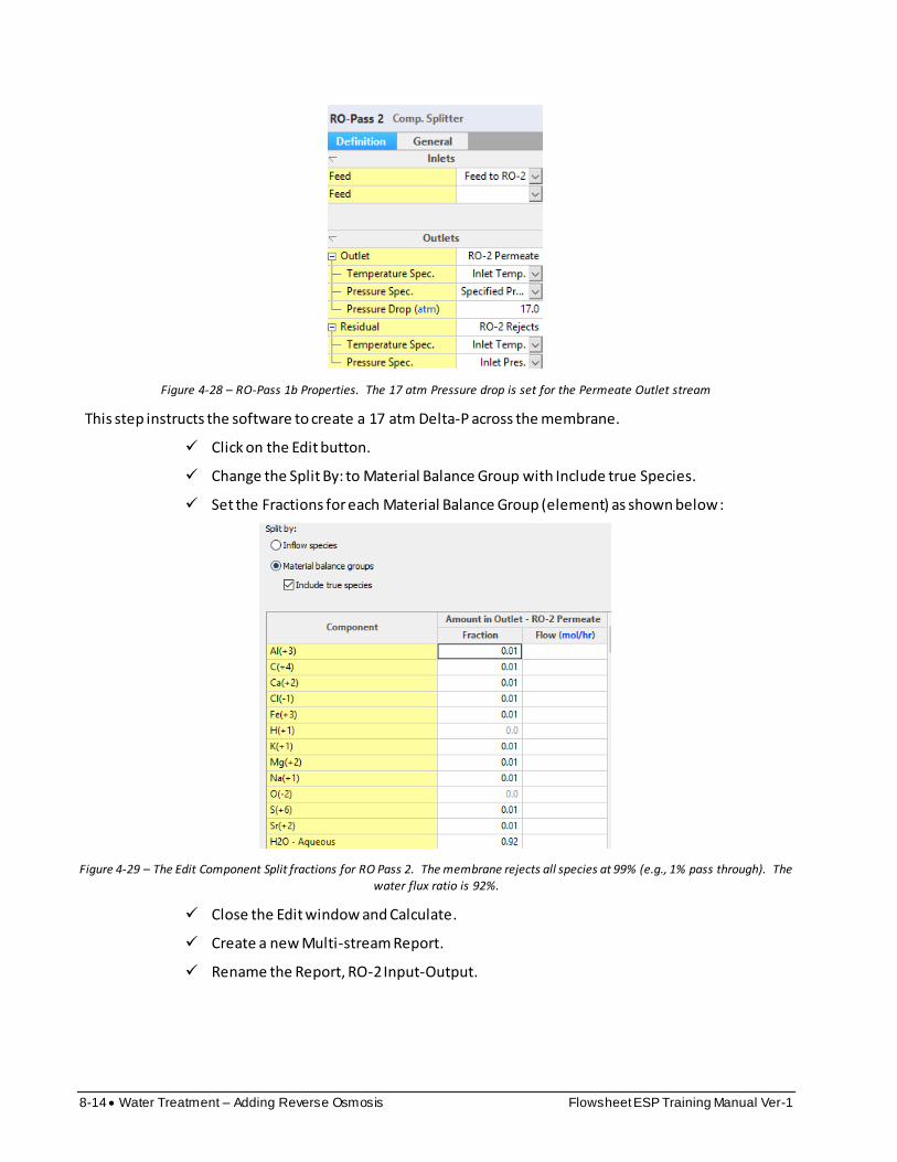
8-14 Water Treatment – Adding Reverse Osmosis Flowsheet ESP Training Manual Ver-1
Figure 4-28 – RO-Pass 1b Properties. The 17 atm Pressure drop is set for the Permeate Outlet stream
This step instructs the software to create a 17 atm Delta-P across the membrane.
Click on the Edit button.
Change the Split By: to Material Balance Group with Include true Species.
Set the Fractions for each Material Balance Group (element) as shown below:
Figure 4-29 – The Edit Component Split fractions for RO Pass 2. The membrane rejects all species at 99% (e.g., 1% pass through). The
water flux ratio is 92%.
Close the Edit window and Calculate.
Create a new Multi-stream Report.
Rename the Report, RO-2 Input-Output.

Flowsheet ESP Training Manual Ver-1 Water Treatment – Adding Reverse Osmosis 8-15
Figure 4-30 – A new multi-stream report is added and named RO-1b Input-Output.
Add the following streams to this report, Feed to RO-2, RO-2 Permeate, and RO-2 Rejects
Compare the total pressure and Osmotic pressures in each stream
Figure 4-31 – The Thermodynamic properties of the inlet and outlet streams of the RO-2 unit
The Delta P is fixed at 17 atm in the RO-Pass 2 Membrane block the Osmotic back pressure is 16.3-0.02=16.3 atm. Thus, the Delta-P exceeds the osmotic back pressure by 0.7 atm, and so sufficient physical pressure exist to enable 92% of the water to pass through the membrane.
Save your case file. It will be used in the next Chapter.
Summary
This chapter introduced the component splitter block which was used to simulate a reverse-osmosis membrane unit. The Component splitter separated material balance groups (MBG) for the cations and anions between the permeate and concentrate streams, and a flow fraction was used to simulate H2O transport through the membrane to the permeate side. In addition to the mechanics of setting up the block, attention was paid to the Delta-P across the membrane and the osmotic back pressure created by the membrane process. It was necessary to confirm that the Delta-P was always greater than the osmotic pressure. Otherwise, the specified water flow rate would not be achieved.