Chapter 2 A simple Absorption Column - Aqueous …courses.aqsim.com/F-ESP/FESP-Chapter02 A...
13
Flowsheet ESP Training Manual Ver-1 A simple Absorption Column 2-1 Chapter 2 A simple Absorption Column The Application There are several types of multi-stage, or column, blocks in Flowsheet ESP. The simplest is the Absorber column. This column consists of a minimum two equilibrium stages, and two inlet and two outlet streams. Figure 2-1 is an example column. It is a four-stage flue gas scrubber. Combustion gas contains various pollutants (SO2, SO3, HCl, H2S, and Hg), which are absorbed into a high pH washing solution. Figure 2-1 – Absorption column for removing pollutants from combustion gases You will build this case in the same two steps as the previous chapter. Step 1 is to create the chemistry model and the step 2 is to build the process. Start the Software. Confirm that a blank case is on the screen. Save this blank case as Section1 – Chapter2 - Absorption Tower. Creating a Chemistry Model As explained in the previous chapter, the chemistry model is one of two modules required for the case. Selecting the thermodynamic method and databases to be used in the Model Click on the Chemistry tab - The start tab for all new cases is the Databanks. This tab contains the thermodynamic framework and specialized database.
Transcript of Chapter 2 A simple Absorption Column - Aqueous …courses.aqsim.com/F-ESP/FESP-Chapter02 A...

Flowsheet ESP Training Manual Ver-1 A simple Absorption Column 2-1
Chapter 2 A simple Absorption Column
The Application There are several types of multi-stage, or column, blocks in Flowsheet ESP. The simplest is the Absorber
column. This column consists of a minimum two equilibrium stages, and two inlet and two outlet streams. Figure 2-1 is an example column. It is a four-stage flue gas scrubber. Combustion gas contains various pollutants (SO2, SO3, HCl, H2S, and Hg), which are absorbed into a high pH washing solution.
Figure 2-1 – Absorption column for removing pollutants from combustion gases
You will build this case in the same two steps as the previous chapter. Step 1 is to create the chemistry model and the step 2 is to build the process.
Start the Software.
Confirm that a blank case is on the screen.
Save this blank case as Section1 – Chapter2 - Absorption Tower.
Creating a Chemistry Model As explained in the previous chapter, the chemistry model is one of two modules required for the case.
Selecting the thermodynamic method and databases to be used in the Model
Click on the Chemistry tab -
The start tab for all new cases is the Databanks. This tab contains the thermodynamic framework and specialized database.

2-2 A simple Absorption Column Flowsheet ESP Training Manual Ver-1
Figure 2-2 - The available framework and databases installed with the software
You will use the Aqueous (H+ ion) framework and will not add any specialized databases to this case.
Keep the existing framework and add no private databases.
Adding the chemical inflows to the model Click on the Inflows tab to access the grid for adding inflows.
This inflows tab contains the grid for adding the chemical components used in the case. The software will automatically generate the aqueous species, gases and solids from this list.
Type the following Inflows to the grid.
N2 SO2
CO2 SO3 O2 HCl
Ar NaOH
The grid should look like the following screen
Figure 2-3 – Entering the molecular inflows.
Click on the Chemistry icon in the Navigator panel and press F2 to change its name. Name it Combustion Gas.
Figure 2-4 – Renaming the Chemistry model
This completes the Chemistry Model Build step. There are additional options, but they are not germane to this example.
Building the Scrubber Process
Adding the Absorber block The first step is to create the block. It is a simple procedure.

Flowsheet ESP Training Manual Ver-1 A simple Absorption Column 2-3
Click on the Flowsheet tab.
Click on the Absorber object in the Library (lower left of the screen) and drag it onto the Worksheet.
Double click on the new block to change its name to Gas Scrubber.
You should notice that the right Properties panel displays the settings for this column.
Figure 2-5 - The Absorber block and its Properties Panel (Definition tab)
Change the Calculation Method to Equilibrium.
This instructs the software that each column stage will calculate to equilibrium; that there will be no mass -transfer limitations.
Change the Number of Stages from 10 to 3.
This action instructs the software that there are three theoretical stages in the column.
Click on the Pressure Profile and enter 1 atm in the stage 3 and stage 1 row.

2-4 A simple Absorption Column Flowsheet ESP Training Manual Ver-1
Adding the Inlet and Outlet streams Click on the Add Stream button in the Toolbar.
Figure 2-6 - The Add Stream button in the toolbar
Create an inlet stream to the Absorber. Add it to the upper left side.
Notice that a separate click is needed to anchor the stream to the unit.
Create a second inlet stream to the bottom of the column.
Lastly, create two outlet streams, on at the top and one at the bottom of the column.
Figure 2-7- the column with the two inlet steams and two outlet streams
Press the ESC key to deactivate the Add Stream button.
The Add stream mode stays active until the ESC key is pressed, or the arrow button is selected , or if
the Add Stream button is clicked a second time
Name the streams as follows
Top inlet Caustic Lower inlet Combustion gas
Top outlet Clean Gas
Bottom outlet Bottoms
Flowsheet ESP Training Manual Ver-1 A simple Absorption Column 2-5
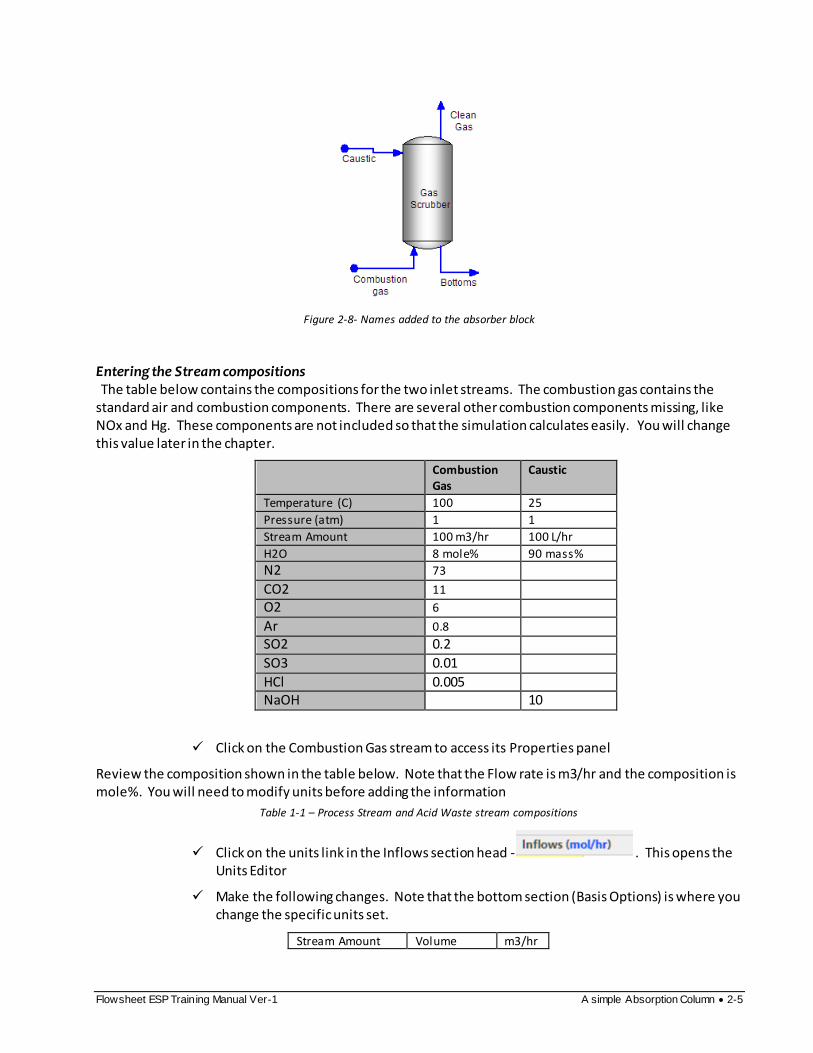
Figure 2-8- Names added to the absorber block
Entering the Stream compositions The table below contains the compositions for the two inlet streams. The combustion gas contains the
standard air and combustion components. There are several other combustion components missing, like NOx and Hg. These components are not included so that the simulation calculates easily. You will change this value later in the chapter.
Combustion Gas
Caustic
Temperature (C) 100 25
Pressure (atm) 1 1
Stream Amount 100 m3/hr 100 L/hr
H2O 8 mole% 90 mass%
N2 73
CO2 11
O2 6
Ar 0.8
SO2 0.2
SO3 0.01
HCl 0.005 NaOH 10
Click on the Combustion Gas stream to access its Properties panel
Review the composition shown in the table below. Note that the Flow rate is m3/hr and the composition is mole%. You will need to modify units before adding the information
Table 1-1 – Process Stream and Acid Waste stream compositions
Click on the units link in the Inflows section head - . This opens the Units Editor
Make the following changes. Note that the bottom section (Basis Options) is where you change the specific units set.
Stream Amount Volume m3/hr

2-6 A simple Absorption Column Flowsheet ESP Training Manual Ver-1
Inflows Mole Fraction Mole%
Vapor Composition Mole Fraction Mole%
Volume m3/hr Mole Fraction Mole%
Click OK to close the Edit Units window.
Enter the composition and conditions for the Combustion Gas.
The composition will not sum to 100%. Therefore, you will use the Normalization option labeled Makeup with Water to set it to 100%.
Change the Normalization Type to Makeup with water - .
Q
The software adjusts the water content to create the 100% composition.
Click on the Caustic stream to access the Properties panel.
Edit its units in the same way, click on one of the linked units in the panel to open the Units Editor window.
Make the following changes:
Stream Amount Volume L/hr

Flowsheet ESP Training Manual Ver-1 A simple Absorption Column 2-7
Inflows Mass Fraction Mass%
Aqueous Composition Mass Fraction Mass%
Volume L/hr Mass Fraction Mass%
The Units Editor should look like this when complete
Close the Edit Units window and enter the composition.
Press the Calculate button to calculate the case
When complete, a Simulation Complete pup-up window appears in the lower right of the window.
Reviewing the resuls Click on the Clean Gas stream to access the Properties panel.
The Properties panel contains a Calculated tab, which is the default view after the simulation converges. It contains two sections - Stream Parameters and Total Apparent flow.

2-8 A simple Absorption Column Flowsheet ESP Training Manual Ver-1
The vent temperature has decreased to 57C and the measured volume decreased to 90 m3/hr.
The Total Apparent units will probably show mol/hr. These are the default software units. They, however, do not help interpretation, and so you will change them.
Click on the Units link in the Total Apparent header to open the Units Editor.
Make the following changes to this panel.
Stream Amount Volume m3/hr
Inflows Mole Fraction Mole%
Vapor Composition Mole Fraction Mole%
Total Composition Mole Fraction Mole%
Volume M3/hr
Mole Fraction Mole%
Close the Units window and view the Clean Gas composition in the panel again.
Flowsheet ESP Training Manual Ver-1 A simple Absorption Column 2-9
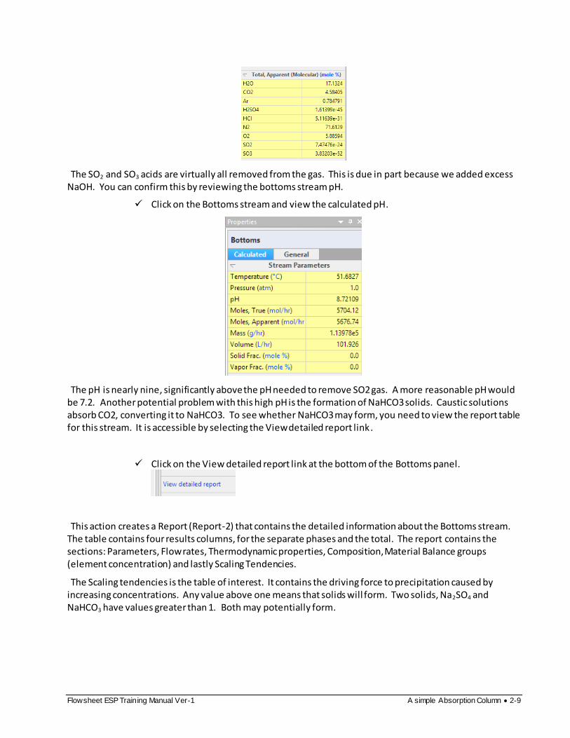
The SO2 and SO3 acids are virtually all removed from the gas. This is due in part because we added excess NaOH. You can confirm this by reviewing the bottoms stream pH.
Click on the Bottoms stream and view the calculated pH.
The pH is nearly nine, significantly above the pH needed to remove SO2 gas. A more reasonable pH would be 7.2. Another potential problem with this high pH is the formation of NaHCO3 solids. Caustic solutions absorb CO2, converting it to NaHCO3. To see whether NaHCO3 may form, you need to view the report table for this stream. It is accessible by selecting the View detailed report link.
Click on the View detailed report link at the bottom of the Bottoms panel.
This action creates a Report (Report-2) that contains the detailed information about the Bottoms stream. The table contains four results columns, for the separate phases and the total. The report contains the sections: Parameters, Flow rates, Thermodynamic properties, Composition, Material Balance groups (element concentration) and lastly Scaling Tendencies.
The Scaling tendencies is the table of interest. It contains the driving force to precipitation caused by increasing concentrations. Any value above one means that solids will form. Two solids, Na2SO4 and NaHCO3 have values greater than 1. Both may potentially form.

2-10 A simple Absorption Column Flowsheet ESP Training Manual Ver-1
Optimizing the Caustic inflow rate The goal is to add sufficient caustic to removed SO2 to the target limits and minimize excess flow. To do
this we need to define a target SO2 limits then control the caustic flow accordingly. According to an excerpt from the document below, the SO2 limits are 180 ng/J energy output, or a flat 95% reduction.
Since this example does not consider energy generated, the target will be the 95% reduction. The SO2 in this combustion gas is 2000 ppmV. Therefore, the 95% reduction converts to 100 ppmV SO2 in the clean gas. You will enter this 100 ppmV values into the column’s Spec/Control window, and instruct the column to adjust the caustic inflow to meet these specifications.
Return to the Flowsheet tab and click on the Gas Scrubber to access the Properties Panel.
Click on the Spec./Controls Edit button in the Parameters section.
The Specification/Control Information window that opens contains the instruction settings for optimizing a tower function.
You can set several types of target specifications, and control several forms of dependent variables. In this case, you will set the SO2 vapor concentration (Specification), and adjust the Caustic flow into the column (Control). They are always set in pairs (i.e., one fixed and one free variable).

Flowsheet ESP Training Manual Ver-1 A simple Absorption Column 2-11
Click on the Add button in the upper right.
Change the Spec. Variable to Vapor Composition
Change the Stage number to 3 .
Stage 3 is the tope stage and is the location of the Clean Gas stream outlet.
Change the Value units to mole% and set the value to 0.01 mole% (equals 100ppmV)
When you press Enter, the Select Components window will open. If it does not, then open it. Click on the Select Components button if the window does not open automatically.
Check the SO2 box and close the window
Change the Control Variable option to Feed Stream Flow
Set the Stage Number to 3 (the stage where the Caustic enters)
When finished your screen should look like the following:
Close the window and calculate.
--------------THE SIMULATION WILL FAIL---------------
When complete, you will receive an ERROR stating that the simulation failed.

2-12 A simple Absorption Column Flowsheet ESP Training Manual Ver-1
This is a common occurrence, and it occurs for several reasons. In this case, it occurred because the 10% Caustic feed is too concentrated. The software cannot find a flow rate that sets the SO2 vapor to 100ppmV. As the Caustic flow decreases (to allow more SO2 to remain in the vapor), it reaches a value where all the liquid added evaporates. A column cannot be all vapor, or it fails to converge.
This is an easily remedied problem; use a less concentrated caustic solution.
Click on the Caustic stream to access the Properties panel.
Change the Normalization type from Prorate to Makeup with water
Change the NaOH content to 0.5%.
Recalculate.
Now the simulation converges quickly.
Click on the Clean Gas stream to access the Properties panel .
View the Total Apparent section, specifically the SO2 value.
The target SO2 is 0.01 mole%, per design.
Click on the Caustic stream to access the Properties panel.
Click on the Calculated tab and view the Volume row.
The calculated volume is 55 L/hr of a 0.5% caustic solution. Had the 10% been kept, approximately 3 L/hr would be required, but the software was unable to converge the tower with this small of a caustic flow rate. This is because the liquid evaporated completely in at least one of the three stages, and the tower will not converge unless water exists at every stage of the tower.
Click on the Bottom stream to review the pH.

Flowsheet ESP Training Manual Ver-1 A simple Absorption Column 2-13
The computed pH is 4.0. If this is lower than expected, it is because the target SO2 vapor composition was set to 100 ppmV. Were the target specification set lower, then the bottoms pH would have increased.
If you want, change the target Specification SO2 value to 10ppmV and review the results again.
Summary
We have completed the first case. It presents the basic mechanics of building and converging a steady-state simulation. In the next chapter, you will expand this case to include additional blocks and chemistry.