
Chapter 3 - Basic Concepts of Natural Gas Processingdownload.xuebalib.com/xuebalib.com.15043.pdf ·...
14
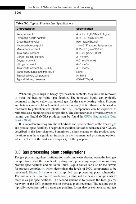
Basic Concepts of Natural Gas Processing 3 3.1 Introduction Raw natural gas from production wells contains a full range of hydrocarbons, carbon dioxide, hydrogen sulfide, nitrogen, water, and other impurities. They can originate from any one of three types of production wells: crude oil wells, gas wells, and condensate wells. Natural gas that comes from crude oil wells is the associated gas. Gas can exist as a gas cap over the crude oil reservoirs, or can be dissolved by the crude oil under pressure. Natural gas from gas wells or from condensate wells, in which there is little or no crude oil, is the nonassociated gas. Gas wells generally produce sour natural gas, while condensate wells produce natural gas condensate or gasoline that is saturated with natural gas. Raw natural gas can also come from unconventional sources. Natural gas can be found in coal seam, as the coal-bed methane gas. It can be the associated gas from shale oil production. Natural gas from offshore wells is another source. The unconventional sources typically contain a high level of CO 2 and nitrogen, which can be found in different parts of the world. These gas reservoirs are believed to be much larger than previous prediction. As technology in exploration and drilling advances, the unconventional reserves are becoming economically attractive and will become an important source of energy supply. The objective of a natural gas processing plant is to produce a methane-rich gas by removing the acid gases, heavy hydrocarbons, nitrogen, water, and other impurities. This chapter gives an overview of the design and function of the different process units within a natural gas processing plant. 3.2 Natural gas processing objectives Raw natural gas stream must be treated to comply with emissions regulations and pipeline gas specifications. Typical pipeline gas specifications are shown in Table 3-1. The specifications are to ensure gas qualities and provide a clean and safe fuel gas to the consumers. The product gas must meet the heating values or Wobbe Indexes specifications, which are required to ensure optimum operation of gas turbines and combustion equipment to minimize emissions. Pipeline operators also require the product gas to be interchangeable and similar in properties with existing pipeline gas. CHAPTER Handbook of Natural Gas Transmission and Processing. http://dx.doi.org/10.1016/B978-0-12-801499-8.00003-1 Copyright © 2015 Elsevier Inc. All rights reserved. 123
Transcript of Chapter 3 - Basic Concepts of Natural Gas Processingdownload.xuebalib.com/xuebalib.com.15043.pdf ·...

Basic Concepts ofNatural Gas Processing 33.1 IntroductionRaw natural gas from production wells contains a full range of hydrocarbons,carbon dioxide, hydrogen sulfide, nitrogen, water, and other impurities. They canoriginate from any one of three types of production wells: crude oil wells, gaswells, and condensate wells. Natural gas that comes from crude oil wells is theassociated gas. Gas can exist as a gas cap over the crude oil reservoirs, or can bedissolved by the crude oil under pressure. Natural gas from gas wells or fromcondensate wells, in which there is little or no crude oil, is the nonassociated gas.Gas wells generally produce sour natural gas, while condensate wells producenatural gas condensate or gasoline that is saturated with natural gas.
Raw natural gas can also come from unconventional sources. Natural gas canbe found in coal seam, as the coal-bed methane gas. It can be the associated gasfrom shale oil production. Natural gas from offshore wells is another source.The unconventional sources typically contain a high level of CO2 and nitrogen,which can be found in different parts of the world. These gas reservoirs arebelieved to be much larger than previous prediction. As technology in explorationand drilling advances, the unconventional reserves are becoming economicallyattractive and will become an important source of energy supply.
The objective of a natural gas processing plant is to produce a methane-richgas by removing the acid gases, heavy hydrocarbons, nitrogen, water, andother impurities. This chapter gives an overview of the design and function of thedifferent process units within a natural gas processing plant.
3.2 Natural gas processing objectivesRaw natural gas stream must be treated to comply with emissions regulations andpipeline gas specifications. Typical pipeline gas specifications are shown inTable 3-1. The specifications are to ensure gas qualities and provide a clean andsafe fuel gas to the consumers. The product gas must meet the heating valuesor Wobbe Indexes specifications, which are required to ensure optimum operationof gas turbines and combustion equipment to minimize emissions. Pipelineoperators also require the product gas to be interchangeable and similar inproperties with existing pipeline gas.
CHAPTER
Handbook of Natural Gas Transmission and Processing. http://dx.doi.org/10.1016/B978-0-12-801499-8.00003-1
Copyright © 2015 Elsevier Inc. All rights reserved.123
When the gas is high in heavy hydrocarbon contents, they must be removedto meet the heating value specification. The removed liquid can typicallycommand a higher value than natural gas for the same heating value. Propaneand butane can be sold as liquefied petroleum gas (LPG). Ethane can be used asfeedstock to petrochemical plants. The C5þ components can be exported torefineries as a blending stock for gasoline. The characteristics of various types ofnatural gas liquid (NGL) products can be found in GPSA Engineering DataBook (2004).
It is important to recognize the definitions and specifications of the treated gasand product specifications. The product specifications of condensate and NGL aredescribed in the later chapters. Sometimes a slight change on the product spec-ifications may have significant impacts on the treatment and processing options,which will affect the cost and complexity of the gas plant.
3.3 Gas processing plant configurationsThe gas processing plant configuration and complexity depend upon the feed gascompositions and the levels of treating and processing required in meetingproduct specifications and emission limits. Liquid values can also be the driversfor process complexity, which determines the levels of NGL components to berecovered. Figure 3-1 shows two simplified gas processing plant schematics.The first scheme is to remove condensate, sulfur, and the heavier components tomeet sales gas specifications. The second scheme is to process the feed gas forrecovery of the NGL components to increase plant revenues. The residue gas istypically recompressed to a sales gas pipeline. It can also be sent to a natural gas
Table 3-1 Typical Pipeline Gas Specifications
Characteristic Specification
Water content 4e7 lbm H2O/MMscf of gas
Hydrogen sulfide content 0.25e1.0 grain/100 scf
Gross heating value 950e1200 Btu/scf
Hydrocarbon dewpoint 14e40 �F at specified pressure
Mercaptans content 0.25e1.0 grain/100 scf
Total sulfur content 0.5e20 grain/100 scf
Carbon dioxide content 2e4 mol%
Oxygen content 0.01 mol% (max)
Nitrogen content 4e5 mol%
Total inerts content (N2 þ CO2) 4e5 mol%
Sand, dust, gums, and free liquid None
Typical delivery temperature Ambient
Typical delivery pressure 400e1200 psig
124
Handbook of Natural Gas Transmission and Processing

liquefaction plant for liquefied natural gas (LNG) production, used as fuel gas topower plants, or as a feedstock to petrochemical plants.
The gas processing plant must be a “fit-for-purpose” design, meeting the projecteconomics and environmental requirements. While contaminants and sulfur mustbe removed to meet emissions requirements as shown in the first scheme, the extentof processing in the second schemes is project specific. It depends on thecommercial agreements between upstream producers and downstream productdistributors and buyers. More details on the contractual terms are discussed later inthis chapter.
3.3.1 Gas plant with hydrocarbon dewpointingRaw gas to a gas processing plant can be relatively lean, that is, containing asmall amount of C2þ hydrocarbons. This lean gas can be processed by theprocess units as shown in Figure 3-2. The main process units consist of acid gasremoval, gas dehydration, and hydrocarbon dewpoint control. There are otheroff-site support systems such as the sulfur recovery, and tail gas treating andsulfur production, which are necessary to meet environmental requirements.If the gas contains liquid condensate, a condensate stabilization unit is required.If the gas contains high levels of nitrogen, nitrogen rejection is required. Otherunits such as gas compression unit may also be required.
3.3.1.1 Inlet facilityFeed gas from production wells arriving at the inlet facility is first separated in theinlet facility, which typically includes slug catchers, separation equipment, andpressure protection system. Typically a highly reliability safety system is installedat the inlet to protect the gas plant from a block discharged emergency condition.
The slug catcher is designed with adequate surge volume to hold the maximumliquid slug during the piping pigging operation and to provide to a steady flow tothe stabilization unit.
FIGURE 3-1
Two different schemes of gas processing plants.
CHAPTER 3 Basic Concepts of Natural Gas Processing
125

The slug catcher is typically located at a safe distance from the gas plant, withadequate separation distance for safety reasons. The design is either a “vesseltype” or a “finger type.” A vessel-type slug catcher consists of a phase separatorfor vapor, liquid, and water and a storage vessel to contain the liquid slug duringpigging. The design is suitable to handle feed gas with high gas to liquid ratio anda steady flow. It is used where there is a space limitation, such as in offshoreplatform installation. The finger-type slug catcher is common in land-basedplants where there are no space constraints. It is less costly than the vesseltype, especially in high-pressure (HP) services. It consists of multiple long piecesof pipes, which provide the surge volume.
Produced gas from the slug catcher is directed to a HP separator, whichprotects the gas plant from upstream system upset. More details about the phaseseparation facilities are presented in Chapter 4.
The water content in the liquids from the slug catcher is separated and sent toa sour water stripper unit. The hydrocarbon liquids are processed in a condensatestabilization unit to reduce its vapor pressure for storage and transport. Theproduced water typically containing monoethylene glycol (MEG) used forhydrate control can be reclaimed in a MEG reclamation unit. Other contaminants,such as corrosion inhibitors and salts content, must be removed before MEG canbe reused in the upstream unit.
Raw Gas
Off gas
HPSeparator
CondensateStabiliza�onUnit
SulfurDegassing
Incinera�on
Off-gas toAtmosphere
Sulfur Recovery Unit
Enriched Acid GasTail Gas
Trea�ng Unit
Sales GasCompression (if required)
NitrogenRejec�on Unit(if required)
HC Dewpoint Control Unit
GasDehydra�on
Unit
Acid Gas Removal Unit
Liquid Sulfur Storage
Solid Sulfur
CondensateTo Export
Condensate Storage
Water Trea�ng Unit
Sour WaterStripping Unit
Slug catcherSulfur
Solidifica�on Unit
C5+Cut
FIGURE 3-2
Process units in a gas plant with hydrocarbon dewpointing.
126
Handbook of Natural Gas Transmission and Processing
3.3.1.2 Condensate stabilizationThe condensate contains dissolved light hydrocarbons and H2S, which must beremoved to meet the export condensate specifications. A condensate stabilizationunit is designed to produce a condensate with 4 ppm H2S and RVP (Reid vaporpressure) specifications, ranging from 8 to 12 psi. The stabilizer overhead vapor iscompressed and recycled to the HP separator. There are different design optionsin configuring the stabilization unit, which are discussed in Chapter 5.
The H2S content in the condensate from the stabilization unit can typicallymeet 10H2S ppmv specifications. However, it may contain higher levels oforganic sulfurs such as COS and mercaptans. If condensate is exported as aproduct, the total sulfur content must be met, and a separate unit for removal ofthe mercaptans content may be necessary. If the condensate is sent to refineries,the condensate can be blended with the refinery feedstock and treated in therefinery units.
3.3.1.3 Acid gas removal unitThe acid gas removal unit is designed to remove the acidic components to meetsales gas sulfur and CO2 specifications. H2S must be removed to meet the salesgas specification of 4 ppmv, or ¼ grains per 100 scf of gas. In addition, COS,mercaptans, and other organic sulfur species must be removed. Consideringtoday’s stringent emission regulations, acid gas removal unit alone may not besufficient to meet the requirements. Treated gas from the acid gas removal unit mayneed to be further treated with additional units, such as molecular sieves or sulfurscavengers. Design details of the acid gas removal units are discussed in Chapter 6.
3.3.1.4 Sulfur recovery and handling unitAcid gas from the amine regenerator contains concentrated H2S, which cannot bevented for safety reasons or flared due to acid gas pollution. If reinjection wellsare available, acid gas can be reinjected back to the reservoirs for sequestration,which would avoid the investment of a sulfur recovery unit. In most instances,where reinjection facility is not available, H2S is processed in a sulfur recoveryunit. The sulfur recovery unit can be coupled with a tail gas treating unit toachieve 99.9% sulfur removal to meet today’s emission target. The designs of thesulfur recovery units are discussed in Chapter 9.
3.3.1.5 Gas dehydration unitTreated gas from the acid gas removal is fed to the gas dehydration unit to meetthe water dewpoint specification for pipeline transmission, typically 7 lbs water/MMscf. In colder climate areas, the water dewpoint specification can be as lowas �40 �F in order to avoid hydrate formation in the pipeline. Depending on theplant capacity and extent of drying, different types of dehydration methods areavailable, including glycol dehydration and solid desiccant (i.e., molecularsieves, silica gels, activated alumina) dehydration. Designs of gas dehydrationsystem are discussed in Chapter 7.
CHAPTER 3 Basic Concepts of Natural Gas Processing
127

3.3.1.6 Hydrocarbon dewpointingThe hydrocarbon dewpoint temperature must be reduced to a lower temperaturethat is below the coldest ambient temperature during transmission. This is toavoid hydrocarbon liquid condensation in the pipeline, which is a safety hazard.Depending on the phase envelop of the pipeline gas, the hydrocarbon dewpointcan actually increase when the pressure is lowered, which must be considered inthe design of the unit. Details of the hydrocarbon dewpoint processes arediscussed in Chapter 8.
3.3.1.7 Nitrogen rejectionNitrogen content in natural gas varies depending on the gas reservoirs. Nitrogencan be naturally occurring in high concentration in some gas fields, such as in theSouth China Sea where 30–50% nitrogen content gas can be found. For onshorefacilities where nitrogen injection is employed for enhanced oil recovery,nitrogen content can also be very high.
When nitrogen is present in high concentrations, it should be removeddownstream of the NGL recovery unit. Heavy hydrocarbons (BTEX aromatics)must be removed in the NGL recovery unit, as these hydrocarbons will solidify inthe cryogenic section of the nitrogen rejection unit. If the gas is used for LNGproduction, the nitrogen content must be removed to below 1 mol% to meet LNGspecification. Nitrogen is not desirable in LNG product, as it will lower theliquefaction temperature, which would increase the power consumption.
Nitrogen removal by cryogenic separation is more efficient than other alter-natives. Membrane separators and molecular sieves can be used for nitrogenrejection, but their processing capacity is relatively limited. They are suitable forbulk separation, and are not economical to meet stringent specifications. Therejected nitrogen would contain a significant amount of hydrocarbons, which maybe an environmental issue. More details on the nitrogen rejection designs arediscussed in Chapter 10.
3.3.1.8 Gas compression and transmissionFeed gas to the gas plant is typically reduced in pressure such that phase separationis feasible. Most often, recompression of the residual gas to the pipeline pressureis necessary. Design details of the natural gas compression and transmissionsystems are discussed in Chapters 11 and 12, respectively.
3.3.2 Gas plant for NGL productionWhen the feed gas contains a significant amount of liquids, the C3þ hydrocarbons,there are economic incentives to produce the LPG and sometimes ethane liquidas byproducts. The liquid facility typically includes storage, pipeline, metering,and custody transfer, and must include safety system to protect against liquidleakage or spillage. This type of plant is complex and costs more than the simplehydrocarbon dewpoint plant.
128
Handbook of Natural Gas Transmission and Processing

Figure 3-3 illustrates a block flow diagram of a gas plant for NGL production.The following sections describe the units that are unique to NGL production.The balance of plant is similar to the hydrocarbon dewpointing plant.
3.3.2.1 CO2 removalCO2 removal is required to meet the sales gas CO2 specification, typically limitedto 2–3 mol%. CO2 may need to be removed to even a lower level to avoid CO2
freezing in the cold section of the NGL recovery unit. Typically, in propanerecovery process, 2 mol% of CO2, can be tolerated as the NGL column operates ata warmer temperature. Deep CO2 removal may not be required, unless the gas issent to a liquefaction unit, which, in this case, would require CO2 to be removeddown to 50 ppmv.
If the NGL recovery unit is used for ethane recovery, the demethanizercolumn would operate at a much lower temperature, which is prone to CO2
freeze. Even CO2 freezing may not be a problem, a good portion of the CO2
will condense with the ethane product, which may not meet the CO2 specificationin the ethane product (typical Y-Grade NGL limits CO2 content in ethane to500 ppmv). When ethane recovery is required, design must ensure that CO2 in thefeed gas to be removed sufficiently to avoid CO2 freezing as well as meeting theCO2 specification of the ethane product.
Raw Gas
HPSeparator
Acid Gas Removal Unit
Sulfur Recovery Unit
Off gas
Slug catcher
CondensateStabiliza�onUnit
SulfurDegassing
Incinera�on
Enriched Acid Gas
Tail GasTrea�ng Unit
Liquid Sulfur Storage
Solid Sulfur
SulfurSolidifica�on Unit
C5+Cut
Water Trea�ng Unit
Sour WaterStripping Unit
Sales Gas
Compression (if required)
Nitrogen Rejec�on Unit(if required)
EthanePropaneButanesCondensate
NGLFractionation
Treating/DryingUnit
NGLRecovery Unit
MercuryRemoval Unit
Off-gas toAtmosphere
Gas Dehydration &Mercaptans Removal Unitutilizing molecular sieves technology
FIGURE 3-3
Process units in a gas plant for NGL production.
CHAPTER 3 Basic Concepts of Natural Gas Processing
129
3.3.2.2 DehydrationFor NGL recovery, the deethanizer or demethanizer must operate at lowtemperatures. This would require sufficient water to be removed to avoidhydrate formation in the columns. If only propane recovery is considered, thecolumn operates at a warmer temperature, at about �60 �F. In this case, the useof DRIZO triethylene glycol (TEG) dehydration may be sufficient. TEG unit ismore compact than molecular sieve unit and is more suitable for offshoredesign. If ethane recovery is required, then molecular sieve dehydration isnecessary. More details of the dehydration system designs are discussed inChapter 7.
3.3.2.3 Mercury removalMercury is invariably present in the feed gas in ppm levels. Mercury removalusing carbon beds or catalytic beds is required to avoid the risks of mercury attackon the brazed aluminum heat exchangers. Brazed aluminum exchangers arecommonly used in NGL recovery process to achieve high NGL recovery.Aluminum material is very reactive with mercury and can be corroded quicklyresulting in failure of the exchangers.
The mercury removal bed is typically designed with mercury removal tobelow 0.01 mg/Nm3. The mercury removal step can be positioned upstream of theacid gas removal unit or downstream of the dehydration unit. Installing themercury removal unit upstream can prevent mercury migration to downstreamunits, ensuring both the sales gas and the liquid products are mercury free. Moredetails of the mercury removal designs are discussed in Chapter 7.
3.3.2.4 NGL recoveryThere are numerous NGL patents and proprietary technologies for NGLrecovery. Unlike acid gas removal unit, the NGL recovery process selectionmust beevaluated based on meeting the NGL recovery levels, feed gas pressure,temperature, gas compositions, and product specifications, as well asNGL recoveryflexibility. The NGL process must be designed to handle a rich gas case and a leangas case. If nitrogen injection is considered in the same formation, the highernitrogen feed gas case must be considered in the design.
Typically, the design of the front section of the NGL recovery unit iscontrolled by the rich gas case operating in the summer, as the refrigeration duty ishigher. However, the lean gas and the high nitrogen gas would control the designof the demethanizer and the residue gas compressor as the gas flow is higher.
The NGL recovery unit can be designed for propane recovery or ethanerecovery. For operating flexibility, the NGL process can be designed for ethanerecovery that can be operated on ethane rejection when ethane margins are low.Another alternative is to design the unit for propane recovery that can be operatedon ethane recovery. More details of the various NGL recovery unit designs arediscussed in Chapter 8.
130
Handbook of Natural Gas Transmission and Processing

NGL product compositions depend on the desirable propane and ethanerecovery. NGL product pump and NGL pipeline must be designed for the ethanerecovery operation as the NGL flow rate and the pipeline pressure are higher.NGL is typically transported to an NGL fractionation center, which wouldproduce the final liquid products. The NGL products may need additionaltreatment and processing to meet the product specifications. Details on NGLfractionation and products treating are discussed in Chapter 8.
3.4 Finding the best gas processing routeThere are various technologies, conventional or proprietary, for configuring the gasprocessing plant. The best process must be selected based on meeting the projectrequirements, economic targets, and environmental requirements. The design mustbe “fit-for-purpose” meeting the immediate requirements but must considermodification of the process for future gas compositions and NGL recoveryrequirements. More importantly, the designs must be reviewed by the plantoperators and have their buy-in (Mokhatab and Meyer, 2009; Mokhatab, 2010).
The design of the front section of the gas plant, such as slug catcher andcondensate stabilization unit, is conventional. Designs of the gas treating unit andsulfur recovery/handling system are more involved, and are dependent on thefeed gas’ acid gas contents. Design of the NGL recovery unit is dependent on thelevels of NGL recovery, energy efficiency, and operation flexibility. In the past,most NGL recovery units are designed for very high propane recovery (typically,99% propane), as NGL is valued significantly higher than natural gas. High NGLrecovery unit requires the use of turboexpander, feed gas, and residue gascompressors, and propane refrigeration, which is very costly compared to thesimple hydrocarbon dewpointing plants. However, with the shale gas, remote gasand distributed gas playing a vital role in the global energy economy, there is noshortage of NGL; the economic driver for maximizing NGL production isbecoming less attractive.
Today’s NGL design trend tends to focus on minimizing capital investment.Ethane demand is driven by incremental demands from new petrochemical plants.Tominimize capital investment, prefabricatedmodular equipment is used to reducefield construction time and lower capital and operating costs. These modular unitscan be prefabricated as packaged units in various capacities, typically 60–100MMscfd, and can be as high as 200 MMscfd. This modular design when properlyexecuted can generate significant value for gas producers and processors.
In summary, there is no single best approach for the gas processing plant.NGL design continues to evolve around the economics of NGL markets. NGLdesigns that are optimized today may not work well in the future when feed gascompositions changes. An optimized gas plant design must be flexible and besuitable for revamp to meet future requirements and project economics, whilepreserving most of the key equipment.
CHAPTER 3 Basic Concepts of Natural Gas Processing
131

3.5 Support systems3.5.1 Utility and off-siteOperating the gas plants requires support from the utility and off-site systems.These typically include power generation, steam generation, heat medium supply,cooling water, instrument and plant air, nitrogen inert gas, fuel gas system, reliefand flare, potable water, and wastewater treater system.
Small gas plants typically purchase electrical power off the local power grid.Larger gas plants or plants in remote areas would generate their own power.For uninterrupted supply, power can be supplied from the power grid as a backupor using an emergency power generator. A diesel generation is typically requiredfor plant black start. A battery power supply is required for life support duringemergency.
Cogeneration plants are energy efficient and can be attractive options forreduction of operating costs, especially where the gas turbine exhaust can be usedfor heating or steam generation. Most large compressors in gas plants use gasengines or gas turbine drivers, which can be integrated with the steam system.Steam is used in gas plants for solvent regeneration and reboilers in NGL recoveryand fractionation units. These units require cooling; and where available, coolingwater is the most economical. In desert areas where water supply is not available,air coolers are the only choice of cooling.
A demineralizer unit is required to supply boiler feed water makeup to steamgenerators and makeup to amine treating units. Wastewater must be treated in awastewater treater before it can be discharged from the facility.
A reliable source of instrument air is critical to the gas plant operation.Typically, instrument air is supplied at about 100–120 psig, and must be dried tomeet �40 �F water dewpoint. The air must be clean and dried to avoid watercondensation and corrosion in the instrument air piping. One or multiple backup aircompressors are required to ensure plant safety and reliability. Plant air can also besupplied from the same air compressors. Air receivers are sized to dampen outfluctuation in demand, and to provide uninterrupted supply of instrument air.
Nitrogen is required for plant purging during start-up. It is also used for sealgas and for blanketing of storage tanks. Nitrogen consumption is typically verylow in gas plant operation. Nitrogen can be produced by membrane separator orpurchased from outside suppliers. In small gas plants, nitrogen can be supplied bynitrogen bottles.
A HP fuel gas and low-pressure fuel gas are required to meet the fuel gasdemands by steam boilers, hot oil furnaces, and gas turbine drivers. Fuel gas mustbe treated and conditioned to meet the sulfur and heating value specifications.
3.5.2 Process controlProcess control has always played a role in gas plants but has become moreimportant over the years as companies try to reduce labor costs. Most plants use
132
Handbook of Natural Gas Transmission and Processing

distributed control system (DCS) for individual units to provide both processcontrol and operation history. Advanced process control (APC) systems, whichare integrated to the DCS systems, provide sophisticated plant control for plantoptimization. APC uses multivariable algorithms that are programmed toperform online optimization. Another commonly used process control issupervisory control and data acquisition (SCADA) system. One important use ofSCADA is the monitoring of field operations, with the capability of controllingthe process unit equipment, flow valves, and compressor stations from the gasplant. Automation requires accurate input data to make the proper controldecisions. These temperature, pressure, flow sensors, and gas analyzers requireconstant maintenance and tuning to ensure accurate data are transmitted to thecomputer system.
3.5.3 Safety systemsA relief and flare system must be provided to ensure plant safety. Multiple flaresare typically installed to allow one flare to be maintained. The flare must bedesigned to protect against feed gas block discharge, as well as relief loads frompower failure and cooling water failure and other failure modes. Proper sizing ofrelief valves, rupture disks is critical to ensure that process unit is protectedduring emergency. During normal operations, the gas plant is designed to avoidventing and flaring. If the plant is flaring mostly methane, the flame is bright butsmokeless. If heavier hydrocarbons are flared, the flame will smoke and isnoticeable. Smoke would create environmental problems. Steam can be injectedto the flare system to maintain a smokeless flare. If the fuel has a low Btu content,fuel gas can be added to ensure complete combustion.
3.6 Contractual agreementsThe gas processing industry performs the processing steps required to make theproduct gas marketable. These functions may include gas gathering, gascompression, and pipeline transmission. The gas qualities must be conditioned tomeet the sales gas specification. In addition to gas purification functions, the gasprocessors may elect to add discretionary activities to recover NGLs, as liquidrevenue can sometimes generate higher revenues.
When new ventures are being evaluated, there are contractual agreements,which must be used to establish the legal framework that defines the gas planteconomics. This is a balance between capital expenditures and operating costs.The type of contract is dependent on the risks and potential rewards. There is nostraightforward answer to the type of agreements, as different companies maytake a different approach, pending on their willingness to take risks. Mostfacilities may have a combination of agreements to hedge the risks.
There are four major types of agreements, which are discussed below.
CHAPTER 3 Basic Concepts of Natural Gas Processing
133

3.6.1 Keep-whole contractsIn the keep-whole contracts, the gas processor agrees to process or conditionthe producer’s gas to meet sales gas specifications and to return to the producer100% of the Btu value of the raw gas in exchange for retaining ownership ofliquids extracted from the gas. The processor usually retains the liability for allprocessing costs and energy costs. The gas price is usually indexed on a spot gasprice or an average of spot gas prices.
One of the variations to the keep-whole agreement is to have a Btu cap orcrude cap clause. The gas price is capped at a maximum price (Btu cap) or amaximum price relative to the price of crude oil (crude cap).
These contracts are more complex, more favorable to the producer, and morerisky to the processor. The producer, in essence, sells the whole hydrocarbonstream, at the price of natural gas on a Btu basis, to the processor. The processormakes or loses money, depending on the price difference between natural gas andthe NGL, which the processor sells.
Most contracts contain penalties for variations from contracted liquid content,impurities, and delivery pressure. Contracts may be set to allow for incrementalvariations from base composition. Contracts are commonly a combination of twoor more of the above basic types.
3.6.2 Flat fees contractsIn fee-based contracts, the producer pays the gas processor a flat fee based on thegas produced. The processor may charge fees for additional services, such as gasgathering, gas compression, and pipeline transmission. In these contracts, theprocessors income is independent of fluctuation of gas and NGL prices.
The gas processor takes custody of the gas and then bears all of the gasprocessing risk. The processor has the benefits of liquid upgrade, along with therisk on volatility, but has to carry all operating costs, such as fuel, power, andtransmission. Some producers/processors would include offset terms to mitigatethe risks of keep-whole contracts or flat-fee contracts.
3.6.3 Percentage of proceeds contractsIn percentage of proceeds contracts, the two parties agree to the percentage of theproceeds from the sale of the gas and liquids. Typically, the producer retains morethan 70% of the proceeds from the sale of all products. In the case of multipleproducers, each has a percentage share of the proceeds, allocated on the contri-bution to the proceeds.
Allocations can be based on the Btu content of the gas delivered at thewellhead for a producer divided by the sum of the Btu content of the gas from allproducers. Both the producers and processors share the effect of gas and NGLprice fluctuations, the cost of gathering and production, and the sales price of thegas and liquids production.
134
Handbook of Natural Gas Transmission and Processing

3.6.4 Processing fee contractsThis is a risk-free agreement from a processor’s standpoint. The producer pays afee based on the gas volume processed, which is generally a flat fee based on thetypes of gas conditioning and processing requirements. If only gas gathering andcompression are required, the fee will be lower than that required to sweeten,drying, and NGL recoveries.
Depending on the processing fees, the liquids may be retained by theproducer. In most contracts, the processor will take title to a portion of the liquids.This arrangement is common in small isolated fields where there is limitedcompetition.
In summary, the processing costs are shared between producer and processorfor capital projects, and the terms depend on the nature of the project and thepotential risks. Capital items that benefit both parties may be cost shared.However, maintenance, replacements, and costs of environment and emissionscompliance are borne by the processor as a cost of staying in business. Situationsarise in which costs are too high for the processor to absorb alone, and producersmust decide to either share the costs or cease production.
ReferencesGPSA Engineering Data Book, twelfth ed., 2004. Gas Processors Suppliers Association
(GPSA), Tulsa, OK, USA.Mokhatab, S., Meyer, P., 2009. Selecting best technology lineup for designing gas
processing units. Paper Presented at Gas Processors Association (GPA) Europe SourGas Processing Conference, Sitges, Barcelona, Spain (May 14–15).
Mokhatab, S., 2010. An optimum lineup for sour gas processing. Petrol. Technol. Quart.37–43. Gas Issue.
CHAPTER 3 Basic Concepts of Natural Gas Processing
135

本文献由“学霸图书馆-文献云下载”收集自网络,仅供学习交流使用。
学霸图书馆(www.xuebalib.com)是一个“整合众多图书馆数据库资源,
提供一站式文献检索和下载服务”的24 小时在线不限IP
图书馆。
图书馆致力于便利、促进学习与科研,提供最强文献下载服务。
图书馆导航:
图书馆首页 文献云下载 图书馆入口 外文数据库大全 疑难文献辅助工具