Chapter 18 Direct Current Circuits. Sources of emf The source that maintains the current in a closed...
34
Chapter 18 Direct Current Circuits
-
Upload
kathryn-blake -
Category
Documents
-
view
233 -
download
0
Transcript of Chapter 18 Direct Current Circuits. Sources of emf The source that maintains the current in a closed...
Chapter 18
Direct Current Circuits
Sources of emf The source that maintains the current in
a closed circuit is called a source of emf Any devices that increase the potential
energy of charges circulating in circuits are sources of emf
Examples include batteries and generators SI units are Volts
The emf is the work done per unit charge
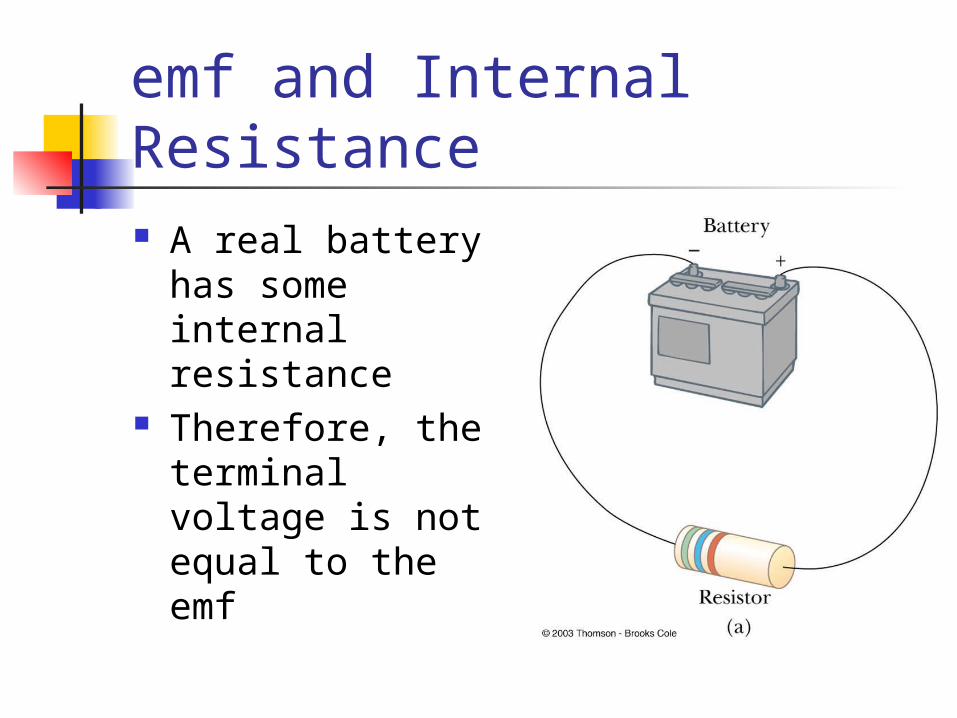
emf and Internal Resistance A real battery has
some internal resistance
Therefore, the terminal voltage is not equal to the emf
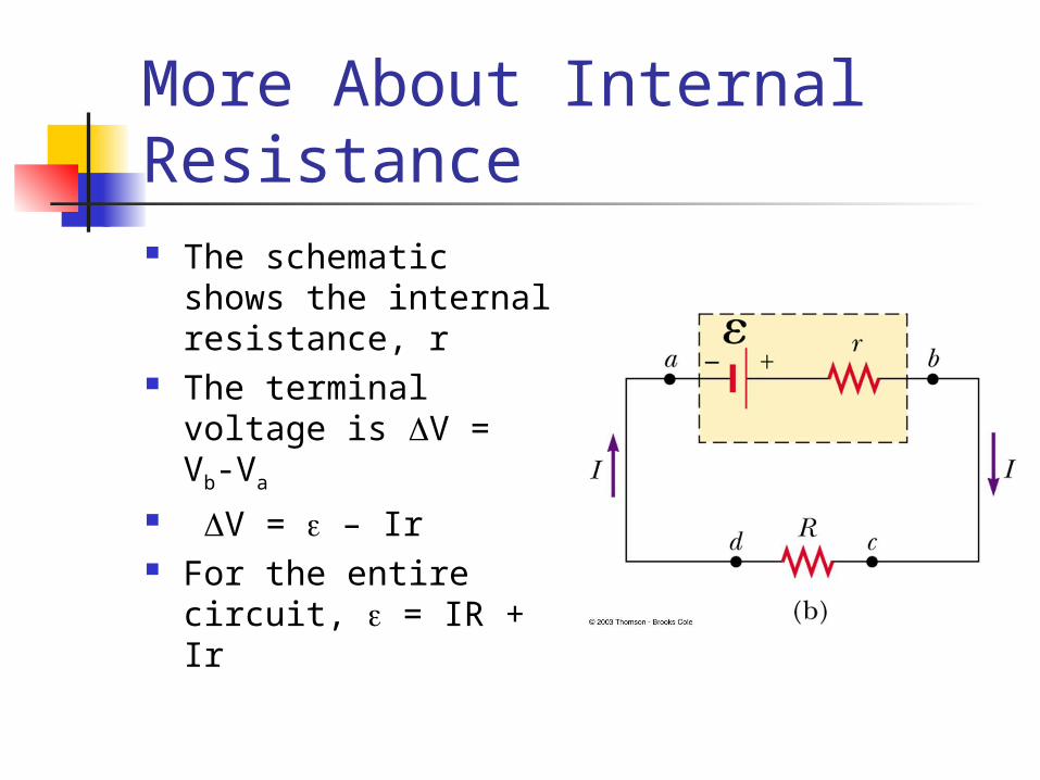
More About Internal Resistance The schematic shows
the internal resistance, r
The terminal voltage is V = Vb-Va
V = – Ir For the entire circuit,
= IR + Ir
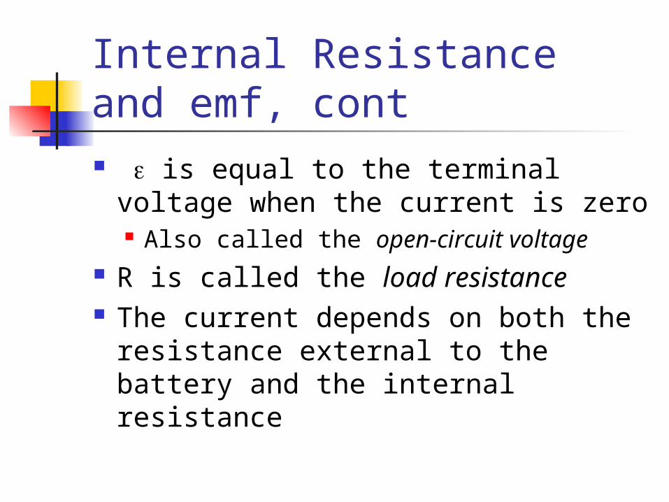
Internal Resistance and emf, cont is equal to the terminal voltage
when the current is zero Also called the open-circuit voltage
R is called the load resistance The current depends on both the
resistance external to the battery and the internal resistance
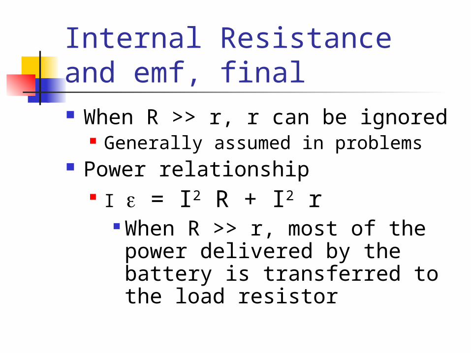
Internal Resistance and emf, final When R >> r, r can be ignored
Generally assumed in problems Power relationship
I = I2 R + I2 r When R >> r, most of the power delivered by the battery is transferred to the load resistor
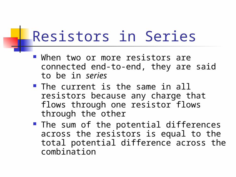
Resistors in Series When two or more resistors are
connected end-to-end, they are said to be in series
The current is the same in all resistors because any charge that flows through one resistor flows through the other
The sum of the potential differences across the resistors is equal to the total potential difference across the combination
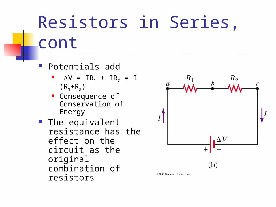
Resistors in Series, cont Potentials add
V = IR1 + IR2 = I (R1+R2)
Consequence of Conservation of Energy
The equivalent resistance has the effect on the circuit as the original combination of resistors
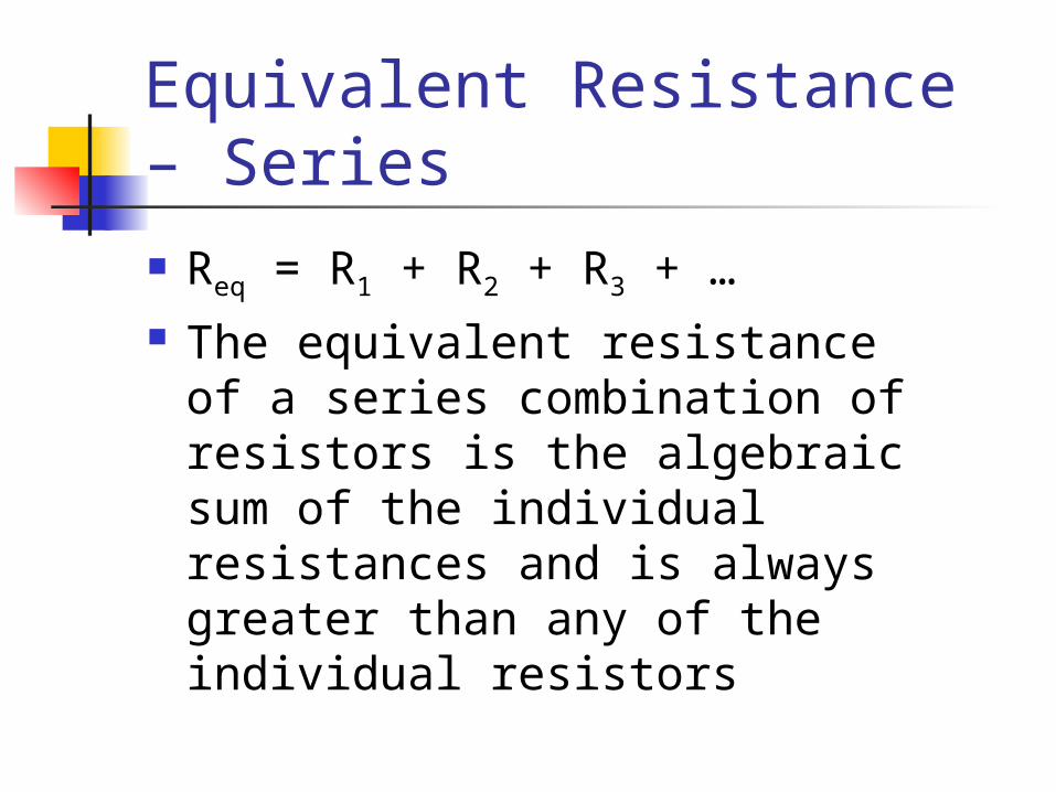
Equivalent Resistance – Series Req = R1 + R2 + R3 + … The equivalent resistance of a
series combination of resistors is the algebraic sum of the individual resistances and is always greater than any of the individual resistors
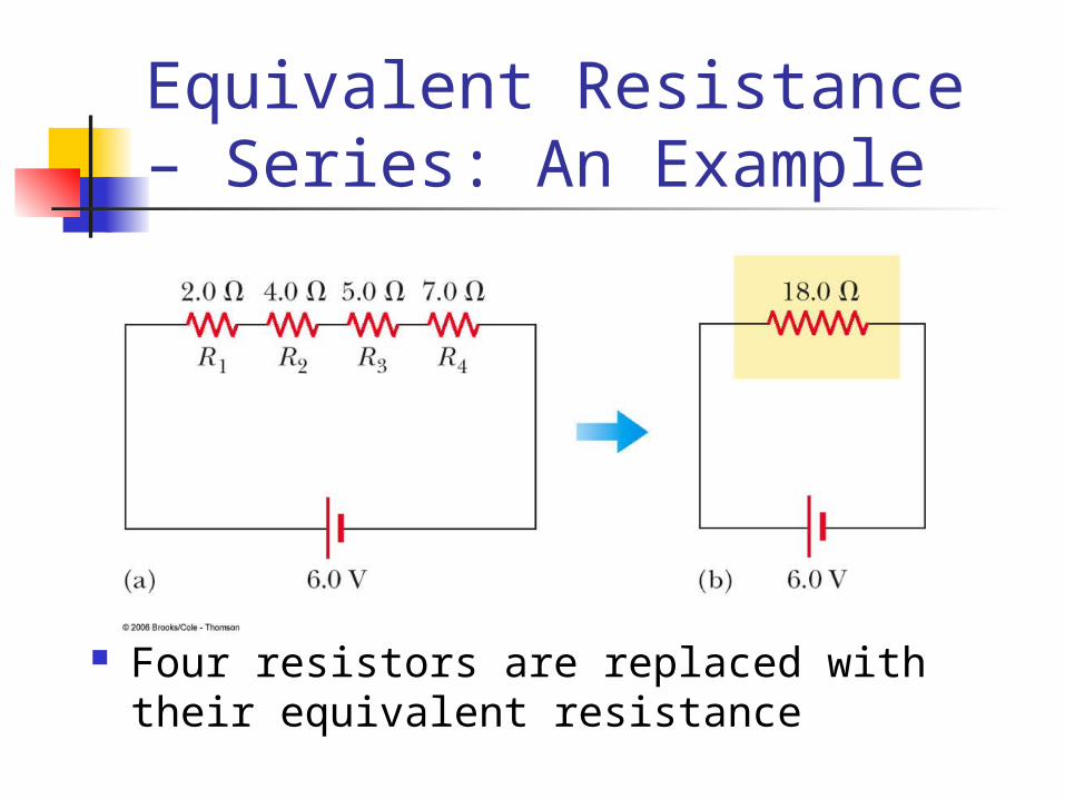
Equivalent Resistance – Series: An Example
Four resistors are replaced with their equivalent resistance

Resistors in Parallel The potential difference across each
resistor is the same because each is connected directly across the battery terminals
The current, I, that enters a point must be equal to the total current leaving that point I = I1 + I2 The currents are generally not the same Consequence of Conservation of Charge
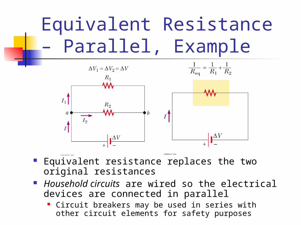
Equivalent Resistance – Parallel, Example
Equivalent resistance replaces the two original resistances
Household circuits are wired so the electrical devices are connected in parallel
Circuit breakers may be used in series with other circuit elements for safety purposes

Equivalent Resistance – Parallel
Equivalent Resistance
The inverse of the equivalent resistance of two or more resistors connected in parallel is the algebraic sum of the inverses of the individual resistance
The equivalent is always less than the smallest resistor in the group
K+++=321eq R
1
R
1
R
1
R
1
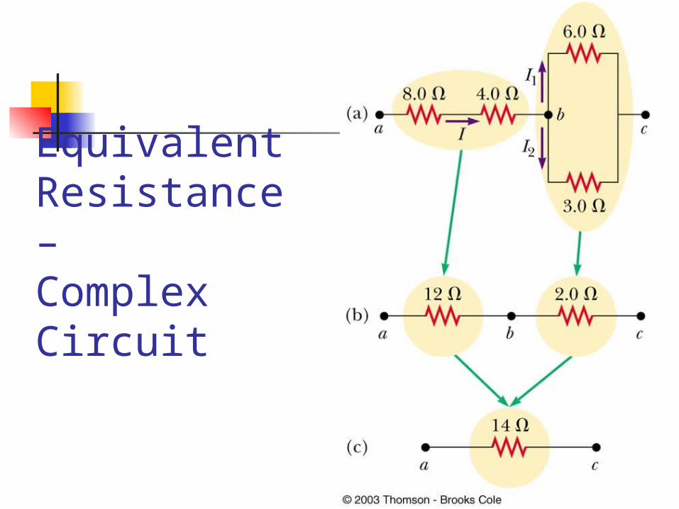
Equivalent Resistance – Complex Circuit
Gustav Kirchhoff 1824 – 1887 Invented
spectroscopy with Robert Bunsen
Formulated rules about radiation

Kirchhoff’s Rules There are ways in which resistors
can be connected so that the circuits formed cannot be reduced to a single equivalent resistor
Two rules, called Kirchhoff’s Rules can be used instead
Statement of Kirchhoff’s Rules Junction Rule
The sum of the currents entering any junction must equal the sum of the currents leaving that junction
A statement of Conservation of Charge
Loop Rule The sum of the potential differences across
all the elements around any closed circuit loop must be zero
A statement of Conservation of Energy
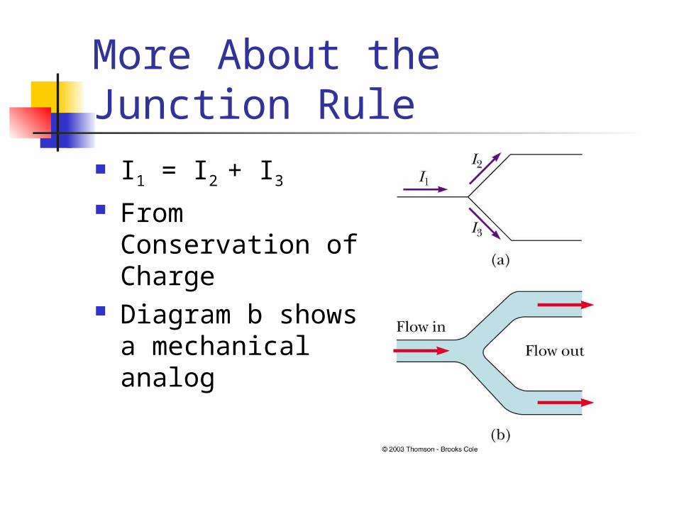
More About the Junction Rule I1 = I2 + I3 From
Conservation of Charge
Diagram b shows a mechanical analog
Setting Up Kirchhoff’s Rules Assign symbols and directions to the
currents in all branches of the circuit If a direction is chosen incorrectly, the
resulting answer will be negative, but the magnitude will be correct
When applying the loop rule, choose a direction for transversing the loop Record voltage drops and rises as they
occur
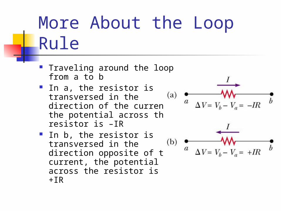
More About the Loop Rule Traveling around the loop
from a to b In a, the resistor is
transversed in the direction of the current, the potential across the resistor is –IR
In b, the resistor is transversed in the direction opposite of the current, the potential across the resistor is +IR
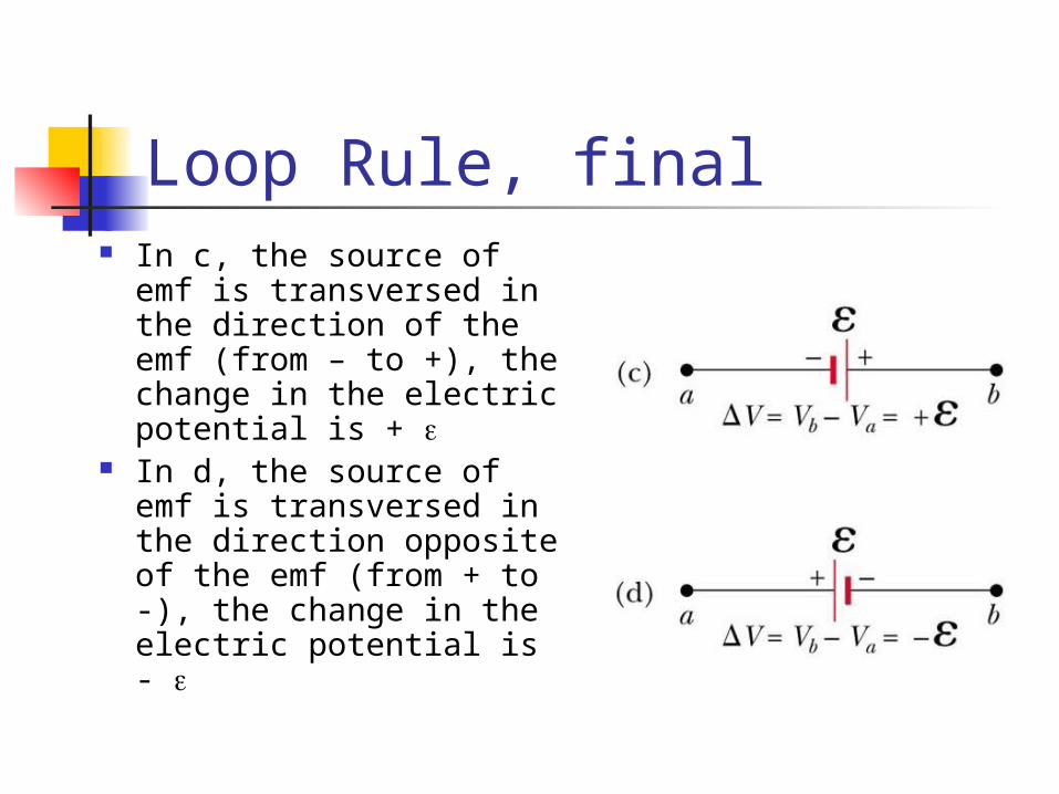
Loop Rule, final In c, the source of emf
is transversed in the direction of the emf (from – to +), the change in the electric potential is +
In d, the source of emf is transversed in the direction opposite of the emf (from + to -), the change in the electric potential is -
Junction Equations from Kirchhoff’s Rules Use the junction rule as often as
needed, so long as, each time you write an equation, you include in it a current that has not been used in a previous junction rule equation In general, the number of times the junction
rule can be used is one fewer than the number of junction points in the circuit

Loop Equations from Kirchhoff’s Rules The loop rule can be used as often
as needed so long as a new circuit element (resistor or battery) or a new current appears in each new equation
You need as many independent equations as you have unknowns

Problem-Solving Strategy – Kirchhoff’s Rules
Draw the circuit diagram and assign labels and symbols to all known and unknown quantities
Assign directions to the currents. Apply the junction rule to any junction in the
circuit Apply the loop rule to as many loops as are
needed to solve for the unknowns Solve the equations simultaneously for the
unknown quantities Check your answers

RC Circuits A direct current circuit may contain
capacitors and resistors, the current will vary with time
When the circuit is completed, the capacitor starts to charge
The capacitor continues to charge until it reaches its maximum charge (Q = C)
Once the capacitor is fully charged, the current in the circuit is zero
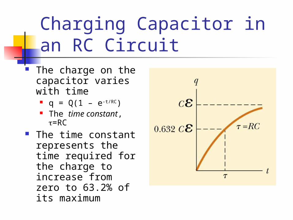
Charging Capacitor in an RC Circuit
The charge on the capacitor varies with time
q = Q(1 – e-t/RC) The time constant,
=RC The time constant
represents the time required for the charge to increase from zero to 63.2% of its maximum

Notes on Time Constant In a circuit with a large time
constant, the capacitor charges very slowly
The capacitor charges very quickly if there is a small time constant
After t = 10 , the capacitor is over 99.99% charged

Discharging Capacitor in an RC Circuit
When a charged capacitor is placed in the circuit, it can be discharged
q = Qe-t/RC The charge decreases
exponentially At t = = RC, the charge
decreases to 0.368 Qmax In other words, in one time
constant, the capacitor loses 63.2% of its initial charge
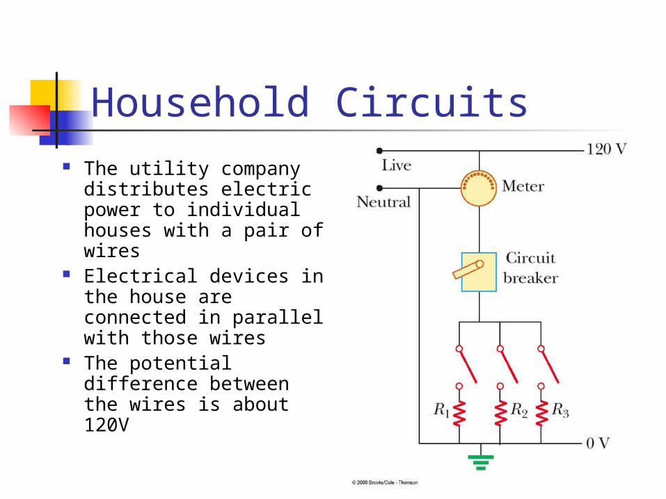
Household Circuits The utility company
distributes electric power to individual houses with a pair of wires
Electrical devices in the house are connected in parallel with those wires
The potential difference between the wires is about 120V
Household Circuits, cont. A meter and a circuit breaker are
connected in series with the wire entering the house
Wires and circuit breakers are selected to meet the demands of the circuit
If the current exceeds the rating of the circuit breaker, the breaker acts as a switch and opens the circuit
Household circuits actually use alternating current and voltage
Electrical Safety Electric shock can result in fatal burns Electric shock can cause the muscles of
vital organs (such as the heart) to malfunction
The degree of damage depends on the magnitude of the current the length of time it acts the part of the body through which it passes

Effects of Various Currents 5 mA or less
Can cause a sensation of shock Generally little or no damage
10 mA Hand muscles contract May be unable to let go a of live wire
100 mA If passes through the body for just a few
seconds, can be fatal
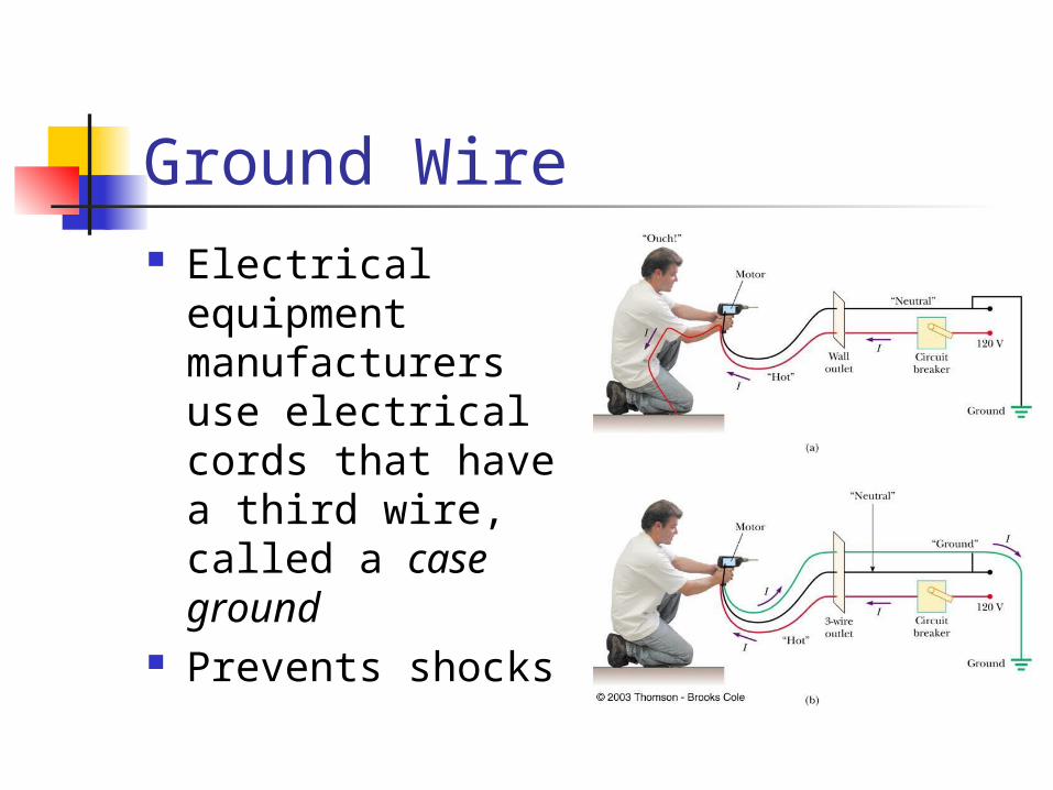
Ground Wire Electrical
equipment manufacturers use electrical cords that have a third wire, called a case ground
Prevents shocks
Ground Fault Interrupts (GFI) Special power outlets Used in hazardous areas Designed to protect people from
electrical shock Senses currents (of about 5 mA or
greater) leaking to ground Shuts off the current when above
this level