Lecture 20-1 Alternating Current (AC) = Electric current that changes direction periodically ac...
20
ture 20- ture 20-1 Alternating Current (AC) lectric current that changes direction periodically ac generator is a device which creates an ac emf/current. ac motor = ac generator run in reverse A sinusoidally oscillating EMF is induced in a loop of wire that rotates in a uniform magnetic field. cos cos B NBA NBA t sin B d NBA t dt 2 2 f T wher e http://www.wvic.com/how-gen-works.htm http://www.pbs.org/wgbh/amex/edison/sfeature/acdc.h
-
date post
20-Dec-2015 -
Category
Documents
-
view
223 -
download
0
Transcript of Lecture 20-1 Alternating Current (AC) = Electric current that changes direction periodically ac...
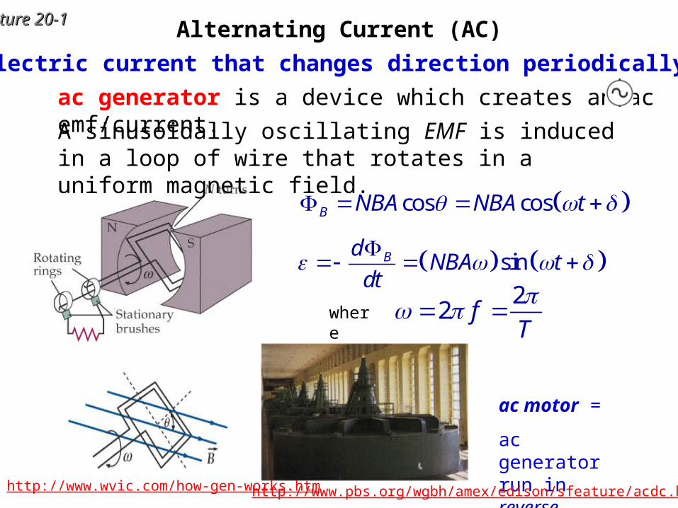
Lecture 20-Lecture 20-11 Alternating Current (AC)
= Electric current that changes direction periodically
ac generator is a device which creates an ac emf/current.
ac motor =
ac generator run in reverse
A sinusoidally oscillating EMF is induced in a loop of wire that rotates in a uniform magnetic field.
cos cosB NBA NBA t
sinBdNBA t
dt
2
2 fT
where
http://www.wvic.com/how-gen-works.htm http://www.pbs.org/wgbh/amex/edison/sfeature/acdc.html
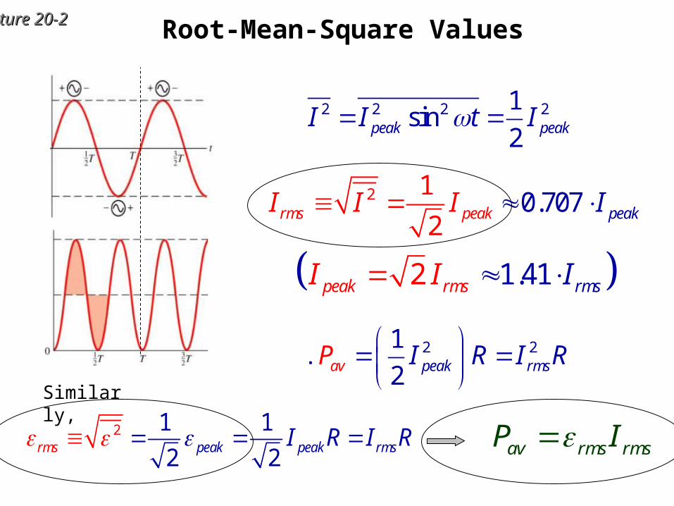
Lecture 20-Lecture 20-22 Root-Mean-Square Values
2 21
2 pea ak sv rmI R I RP
2 0.71
02
7rms pea peakkI I I I
Similarly,
2 1 1
2 2pear k p ss k rmm eaI R I R av rms rmsP I
2 2 2 21sin
2peak peakI I t I
1.412peak rms rmsI I I
Lecture 20-Lecture 20-33
--
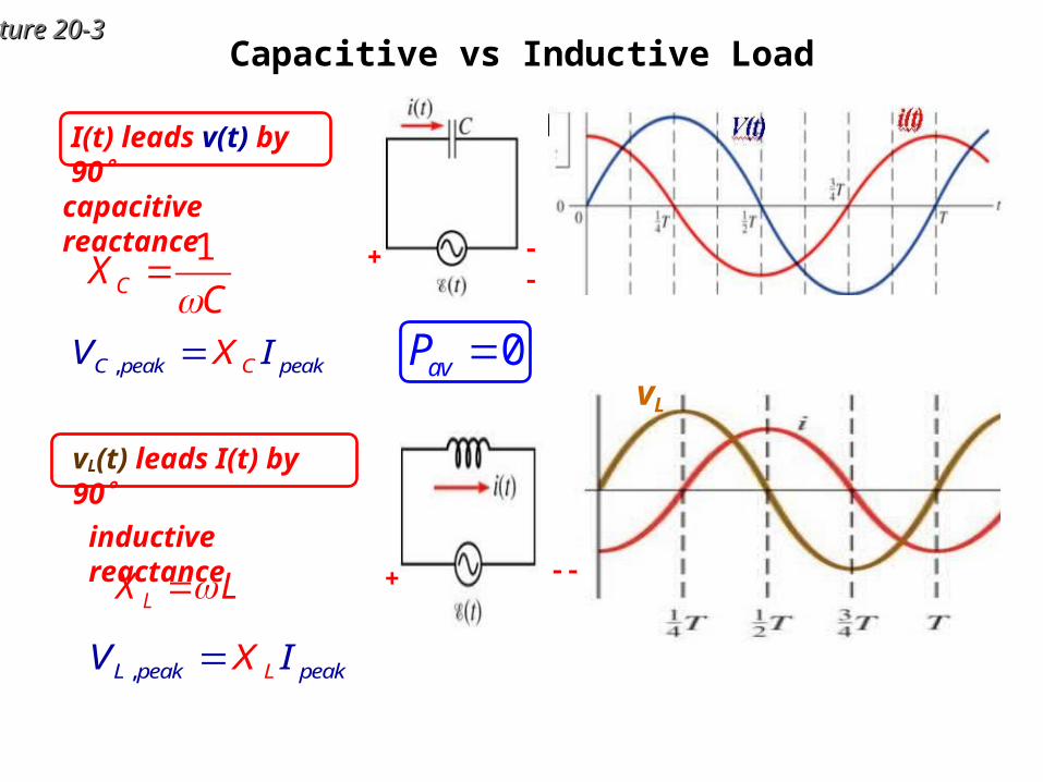
Capacitive vs Inductive Load
I(t) leads v(t) by 90
1CX
C
capacitive reactance
+
--+
vL(t) leads I(t) by 90
LX Linductive reactance
,L peak p akL eV IX
,C peak p akC eV IX 0avP vL
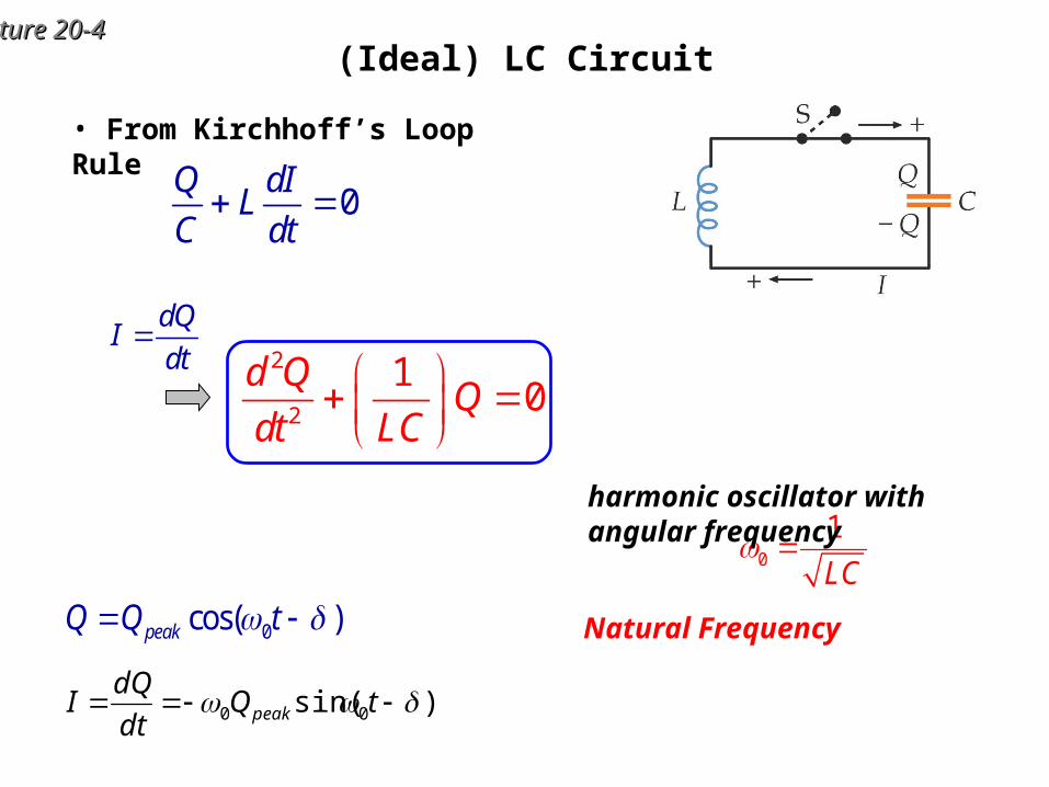
Lecture 20-Lecture 20-44(Ideal) LC Circuit
0cos( )peakQ Q t
• From Kirchhoff’s Loop Rule
0Q dI
LC dt
0
1
LC
Natural Frequency
harmonic oscillator with angular frequency
2
2
10
d QQ
dt LC
dQI
dt
)sin( 00 tQdt
dQI peak

Lecture 20-Lecture 20-55Mechanical Analogy
2 21 1, ,
2 2
dxU kx K mv v
dt
max0,U K K
max , 0U U K max , 0U U K
.E const U K harmonic oscillator with
0
k
m
No friction = No dissipation
2
020
d x k kx
dt m m
0 0 / 2f
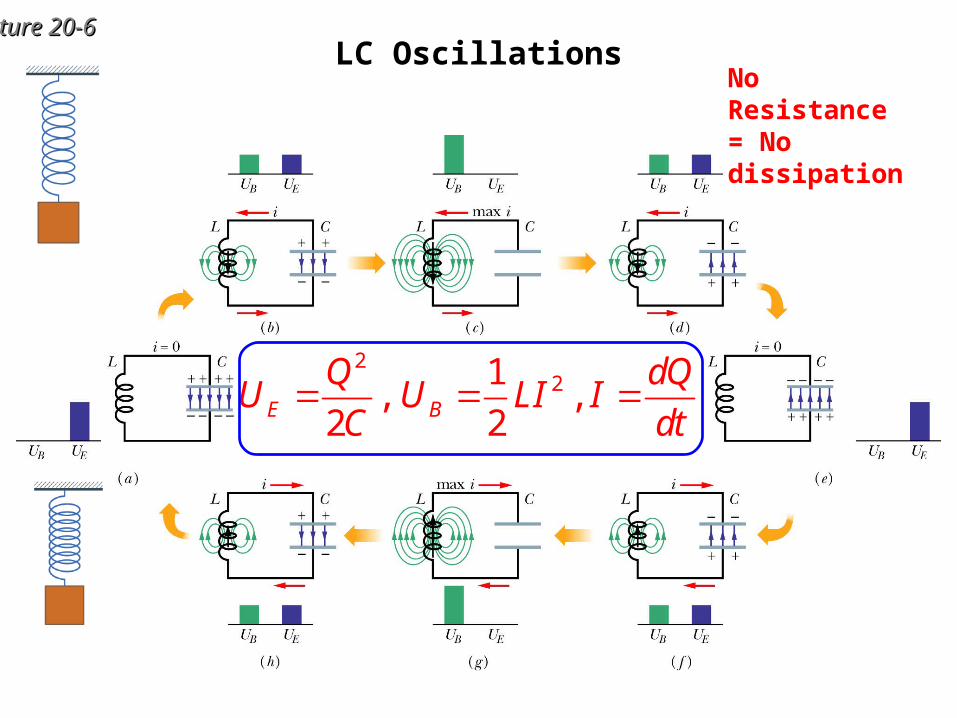
Lecture 20-Lecture 20-66LC Oscillations
221
, ,2 2E B
Q dQU U LI I
C dt
No Resistance = No dissipation
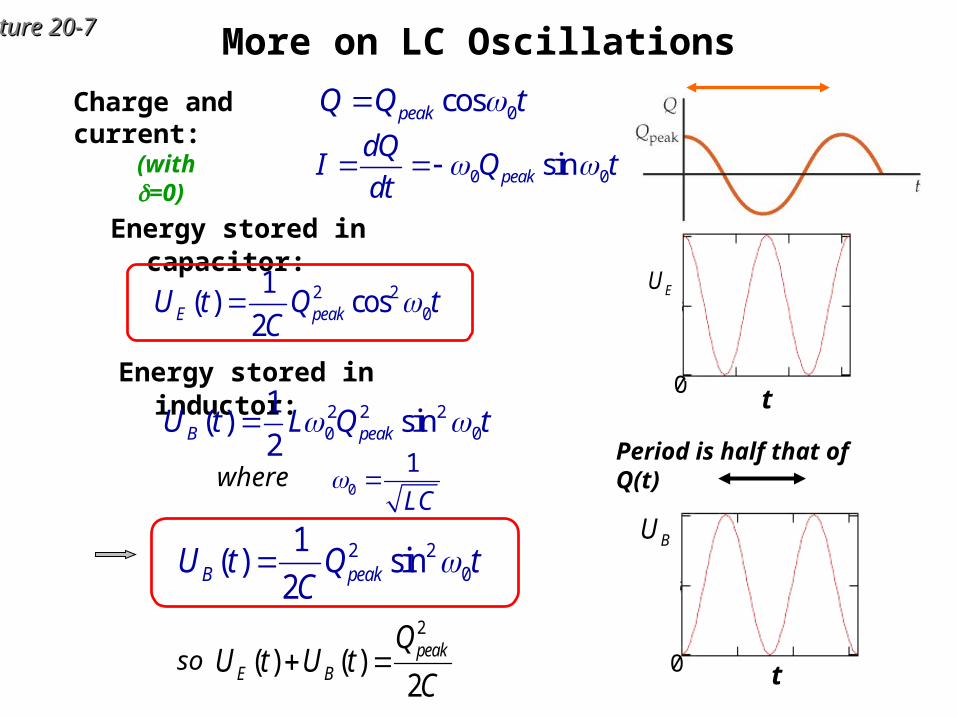
Lecture 20-Lecture 20-77 More on LC Oscillations
Energy stored in capacitor:
2 20
1( ) cos
2E peakU t Q tC
t0
EU
0 t
BU
Energy stored in inductor:2 2 20 0
1( ) sin
2B peakU t L Q t
0
1
LC where
2 20
1( ) sin
2B peakU t Q tC
2
( ) ( )2
peakE B
QU t U t
C so
0 0sinpeak
dQI Q t
dt
Charge and current: 0cospeakQ Q t
(with =0)
Period is half that of Q(t)
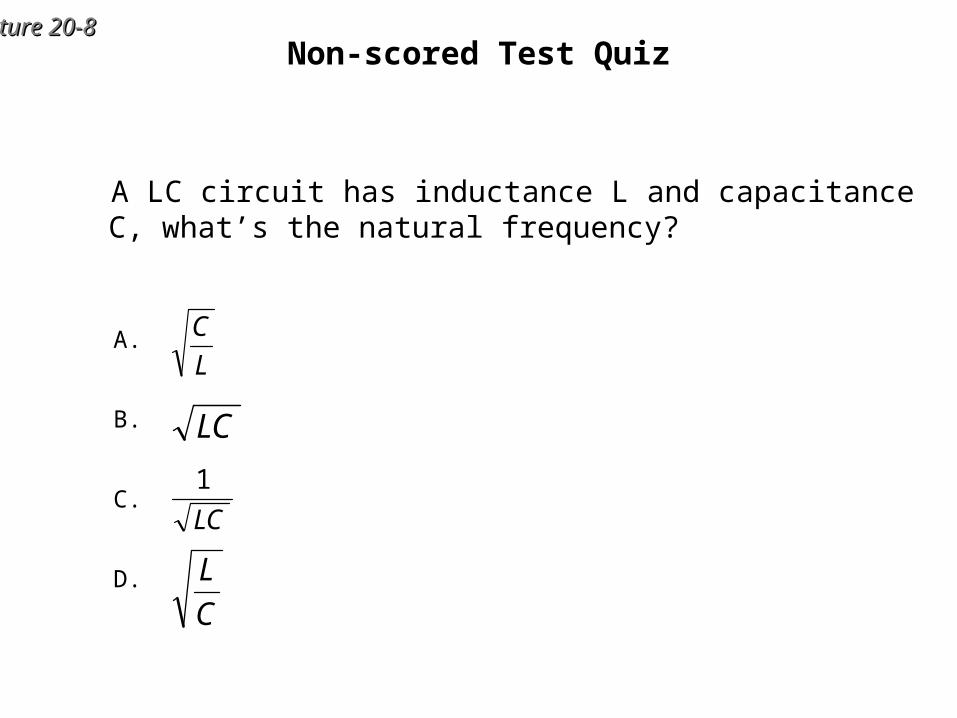
Lecture 20-Lecture 20-88Non-scored Test Quiz
A LC circuit has inductance L and capacitance C, what’s the natural frequency?
LC
1
LC
C
L
L
CA.
B.
C.
D.

Lecture 20-Lecture 20-99Series RLC Circuits
The resistance R may be a separate component in the circuit, or the resistance inherent in the inductor (or other parts of the circuit) may be represented by R.
Finite R Energy dissipation
damped oscillationonly if R is “small”
0dI Q
L IRdt C
2
2
10
d Q dQL R Q
dt dt C
2
20
d x dxm b kx
dt dt
multiply by I2
2 210
2 2
d d QLI I R
dt dt C
For large R
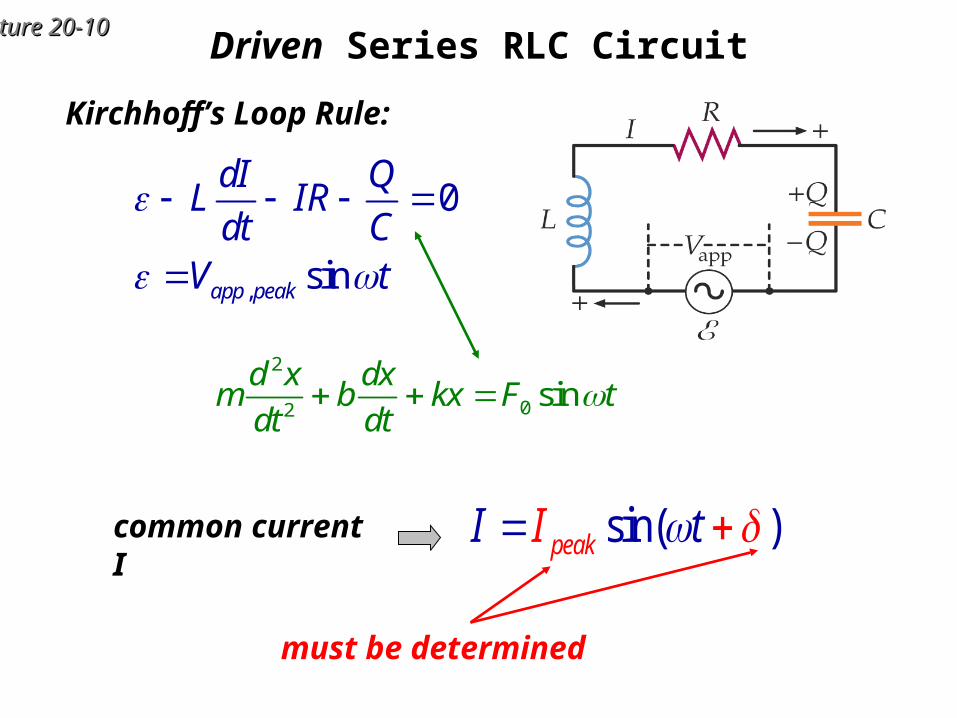
Lecture 20-Lecture 20-1010Driven Series RLC Circuit
Kirchhoff’s Loop Rule:
,
0
sinapp peak
dI QL IR
dt CV t
common current I sin( )peakII t
must be determined
2
02sin
d x dxm b kx F t
dt dt
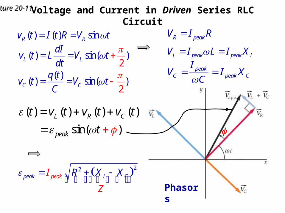
Lecture 20-Lecture 20-1111Voltage and Current in Driven Series RLC Circuit
R peakV I R
L peak peak LV I L I X
peakC peak C
IV I X
C
22peak L CpeakI
Z
R X X
( ) sin( )2L L
dIv t L V t
dt
( )( ) sin( )
2C C
q tv t V t
C
( ) ( ) sinR Rv t I t R V t
( ) ( ) ( ) ( )
sin( )L R C
peak
t v t v t v t
t
Phasors

Lecture 20-Lecture 20-1212
Impedance in Driven Series RLC Circuit
1
tan , cosL C
R
LV V RCV R Z
22 1
Z R LC
impedance,
22peak L CpeakI
Z
R X X
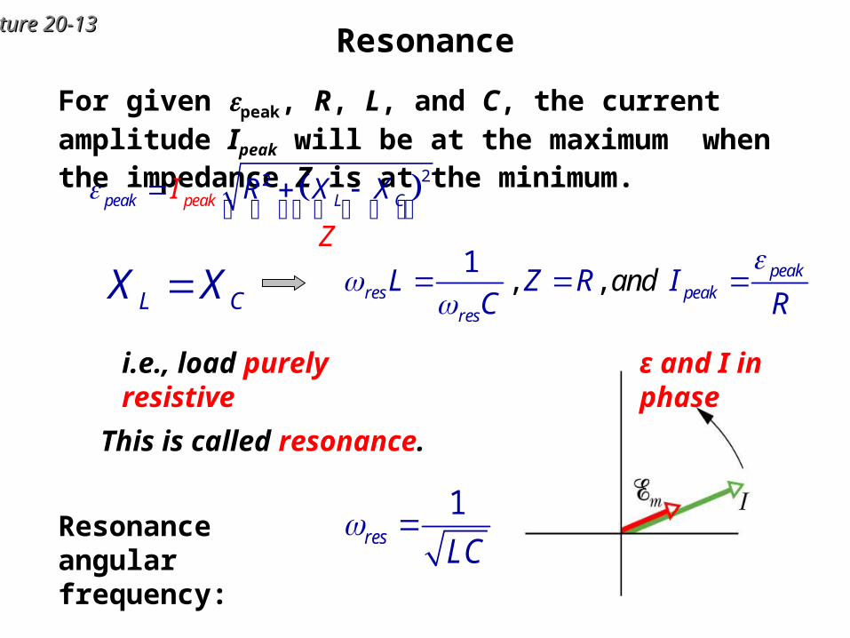
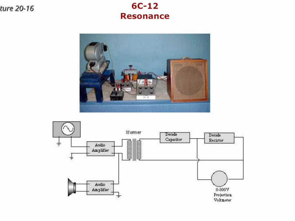
Lecture 20-Lecture 20-1313Resonance
For given peak, R, L, and C, the current amplitude Ipeak will be at the maximum when the impedance Z is at the minimum.
1res
LC Resonance angular
frequency:
This is called resonance.
i.e., load purely resistive ε and I in phase
22peak L CpeakI
Z
R X X
, ,1 peak
res peakres
aL Z nRC
d IR
L CX X
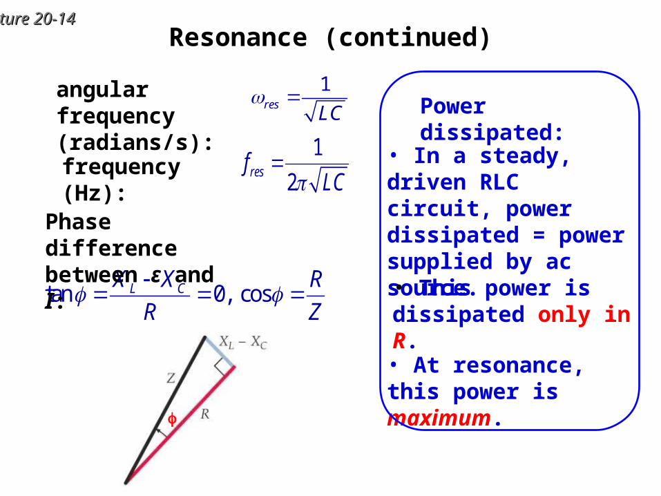
Lecture 20-Lecture 20-1414Resonance (continued)
1res
LC angular frequency
(radians/s):
• In a steady, driven RLC circuit, power dissipated = power supplied by ac source.
• This power is dissipated only in R.
• At resonance, this power is maximum.
Power dissipated:
1
2resf
LCfrequency (Hz):
tan 0, cosL CX X R
R Z
Phase difference between ε and I:
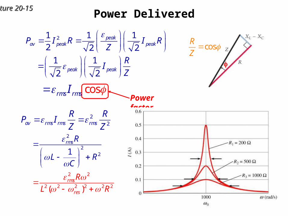
Lecture 20-Lecture 20-1515Power Delivered
21 1 1
2 2 2peak
av peak peakP I R I RZ
1 1
2 2peak peak
RI
Z
Power factorcosrms rmsI
22av rms rms rms
R RP I
Z Z
2 2
2 2 2 2
2
2
2 2
2
( )
1
rms
res
rms
R
L R
R
L RC
cosR
Z
Lecture 20-Lecture 20-1616
Lecture 20-Lecture 20-1717Transformer
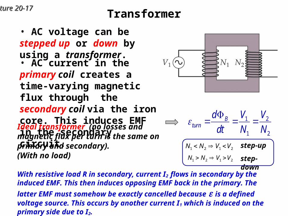
• AC voltage can be stepped up or down by using a transformer.
• AC current in the primary coil creates a time-varying magnetic flux through the secondary coil via the iron core. This induces EMF in the secondary circuit.
Ideal transformer (no losses and magnetic flux per turn is the same on primary and secondary). (With no load)
1 2
1 2
Bturn
d V V
dt N N
step-up
step-down
1 2 1 2N N V V
1 2 1 2N N V V
With resistive load R in secondary, current I2 flows in secondary by the induced EMF. This then induces opposing EMF back in the primary. The latter EMF must
somehow be exactly cancelled because is a defined voltage source. This occurs by another current I1 which is induced on the primary side due to I2.
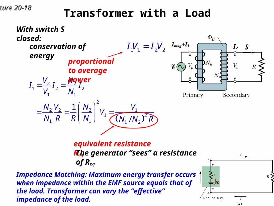
Lecture 20-Lecture 20-1818Transformer with a Load
2 21 2 2
1 1
2
2 2 2 11 2
1 1 1 2
1
/
V NI I I
V N
N V N VV
N R R N N N R
With switch S closed:
1 1 2 2I V I Vconservation of energy
proportional to average power
SImag+I1 I2
equivalent resistance Req
The generator “sees” a resistance of Req
Impedance Matching: Maximum energy transfer occurs when impedance within the EMF source equals that of the load. Transformer can vary the “effective” impedance of the load.
Lecture 20-Lecture 20-1919
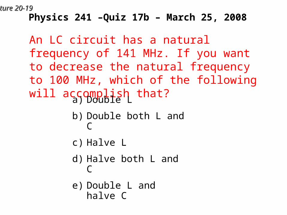
Physics 241 –Quiz 17b – March 25, 2008
An LC circuit has a natural frequency of 141 MHz. If you want to decrease the natural frequency to 100 MHz, which of the following will accomplish that?
a) Double L
b) Double both L and C
c) Halve L
d) Halve both L and C
e) Double L and halve C
Lecture 20-Lecture 20-2020
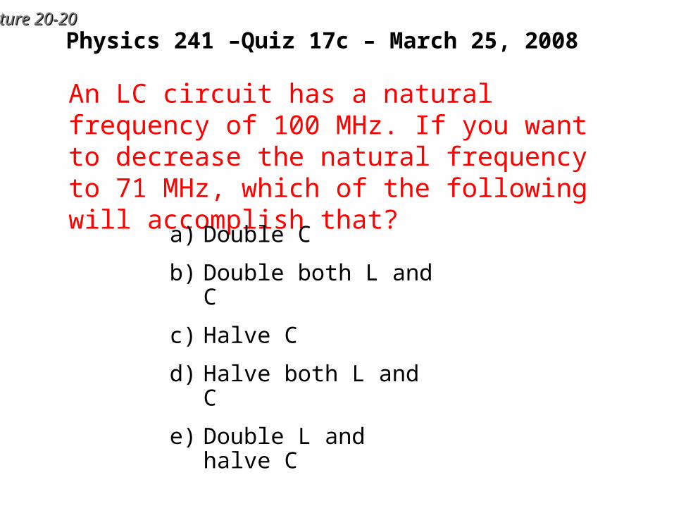
Physics 241 –Quiz 17c – March 25, 2008
An LC circuit has a natural frequency of 100 MHz. If you want to decrease the natural frequency to 71 MHz, which of the following will accomplish that?
a) Double C
b) Double both L and C
c) Halve C
d) Halve both L and C
e) Double L and halve C