Chapter 1-4 - Intersection Design - VHB.com
73
Intersection Design 1.4‐1 SECTION 1, CHAPTER 4 Intersection Design 4.1 Introduction An intersection is the area where two or more streets join or cross at‐grade. The intersection includes the areas needed for all modes of travel: pedestrian, bicycle, motor vehicle, and transit. Thus, the intersection includes not only the pavement area, but typically the adjacent sidewalks and pedestrian curb cut ramps. The intersection is defined as encompassing all alterations (for example, turning lanes) to the otherwise typical cross‐sections of the intersecting streets. Intersections are a key feature of street design in four respects: Focus of activity ‐ The land near intersections often contains a concentration of travel destinations. Conflicting movements ‐ Pedestrian crossings and motor vehicle and bicycle turning and crossing movements are typically concentrated at intersections. Traffic control ‐ At intersections, movement of users is assigned by traffic control devices such as yield signs, stop signs, and traffic signals. Traffic control often results in delay to users traveling along the intersecting roadways, but helps to organize traffic and decrease the potential for conflict. Capacity ‐ In many cases, traffic control at intersections limits the capacity of the intersecting roadways, defined as the number of users that can be accommodated within a given time period. This chapter describes the considerations and design parameters for intersections. The chapter begins by outlining definitions and key elements, and then describes the characteristics of intersection users, intersection types and configurations, capacity and quality of service considerations, geometric design elements, and other considerations.
Transcript of Chapter 1-4 - Intersection Design - VHB.com

Intersection Design 1.4‐1
SECTION 1, CHAPTER 4
Intersection Design
4.1 Introduction
Anintersectionistheareawheretwoormorestreetsjoinorcrossat‐grade.Theintersectionincludestheareasneededforallmodesoftravel:pedestrian,bicycle,motorvehicle,andtransit.Thus,theintersectionincludesnotonlythepavementarea,buttypicallytheadjacentsidewalksandpedestriancurbcutramps.Theintersectionisdefinedasencompassingallalterations(forexample,turninglanes)totheotherwisetypicalcross‐sectionsoftheintersectingstreets.Intersectionsareakeyfeatureofstreetdesigninfourrespects:
Focusofactivity‐Thelandnearintersectionsoftencontainsaconcentrationoftraveldestinations.
Conflictingmovements‐Pedestriancrossingsandmotorvehicleandbicycleturningandcrossingmovementsaretypicallyconcentratedatintersections.
Trafficcontrol‐Atintersections,movementofusersisassignedbytrafficcontroldevicessuchasyieldsigns,stopsigns,andtrafficsignals.Trafficcontroloftenresultsindelaytouserstravelingalongtheintersectingroadways,buthelpstoorganizetrafficanddecreasethepotentialforconflict.
Capacity‐Inmanycases,trafficcontrolatintersectionslimitsthecapacityoftheintersectingroadways,definedasthenumberofusersthatcanbeaccommodatedwithinagiventimeperiod.
Thischapterdescribestheconsiderationsanddesignparametersforintersections.Thechapterbeginsbyoutliningdefinitionsandkeyelements,andthendescribesthecharacteristicsofintersectionusers,intersectiontypesandconfigurations,capacityandqualityofserviceconsiderations,geometricdesignelements,andotherconsiderations.

1.4‐2 Intersection Design DRAFT
4.1.1 Intersection Users
Allroadwayusersareaffectedbyintersectiondesignasdescribedbelow:
Pedestrians.Keyelementsaffectingintersectionperformanceforpedestriansare:(1)amountofright‐of‐wayprovidedforthepedestrianincludingbothsidewalkandcrosswalkwidth,accuracyofslopesandcrossslopesoncurbcutrampsandwalkways,audibleand/ortactilecuesforpeoplewithlimitedsight,andabsenceofobstaclesinaccessiblepath;(2)crossingdistanceandresultingdurationofexposuretoconflictswithmotorvehicleandbicycletraffic;(3)volumeofconflictingtraffic;and(4)speedandvisibilityofapproachingtraffic.
Bicyclists.Keyelementsaffectingintersectionperformanceforbicyclesare:(1)degreetowhichpavementissharedorusedexclusivelybybicycles;(2)relationshipbetweenturningandthroughmovementsformotorvehiclesandbicycles;(3)trafficcontrolforbicycles;(4)differentialinspeedbetweenmotorvehicleandbicycletraffic;and(5)visibilityofthebicyclist.
Motorvehicles.Keyelementsaffectingintersectionperformanceformotorvehiclesare:(1)typeoftrafficcontrol;(2)vehicularcapacityoftheintersection,determinedprimarilyfromthenumberoflanesandtrafficcontrol(althoughthereareotherfactors);(3)abilitytomaketurningmovements;(4)visibilityofapproachingandcrossingpedestriansandbicycles;and(5)speedandvisibilityofapproachingandcrossingmotorvehicles.
Transit.Whentransitoperationsinvolvebuses,theysharethesamekeycharacteristicsasvehicles.Inaddition,transitoperationsmayinvolveatransitstopatanintersectionarea,andinfluencepedestrian,bicycle,andmotorvehicleflowandsafety.
Ownersandusersofadjacentlandoftenhaveadirectinterestinintersectiondesign,particularlywheretheintersectionissurroundedbyretail,commercial,historicorinstitutionallanduses.Primaryconcernsincludemaintenanceofvehicularaccesstoprivateproperty,turnrestrictions,consumptionofprivatepropertyforright‐of‐way,andprovisionofsafe,convenientpedestrianaccess.
4.1.2 Intersection Design Process
Theneedforintersectionimprovementisidentifiedandvariousoptionsforaddressingthisneedareconsideredandanalyzed.Thespecificdesignelementsofintersectionsmayimpactanyorallpotentialusers.Sections4.2through4.6definekeytermsanddiscussintersectionusers,configurations,trafficcontrol,capacity,andqualityofservice.Section4.7describestherangesofphysicaldimensionsandtheoperationalcharacteristicsofeachintersectiondesignelement.

Section 1 – Chapter 4
Intersection Design 1.4‐3
4.2 Definitions and Key Elements
Themajorstreetistypicallytheintersectingstreetwithgreatertrafficvolume,largercross‐section,andhigherfunctionalclass.Theminorstreetistheintersectingstreetlikelytohavelesstrafficvolume,smallercross‐sectionandlowerfunctionalclassificationthanthemajorstreet.Thetermintersectionencompassesnotonlytheareaofpavementjointlyusedbytheintersectingstreets,butalsothosesegmentsoftheintersectingstreetsaffectedbythedesign.Thus,thosesegmentsofstreetsadjacenttotheintersectionforwhichthecross‐sectionorgradehasbeenmodifiedfromitstypicaldesignareconsideredpartoftheintersection.Exhibit4‐1summarizestheextentandterminologyusedtodefineanintersection.
Exhibit 4‐1 Intersection Terminology
Source: Adapted from A Policy on the Geometric Design of Streets and Highways, AASHTO, 2004.
1.4‐4 Intersection Design DRAFT
Twogeometricfeaturesarecommontoallintersections.Theangleofintersectionisformedbytheintersectingstreets’centerlines.Wheretheangleofintersectiondepartssignificantly(morethanapproximately20degrees)fromrightangles,theintersectionisreferredtoasaskewedintersection.Intersectionlegsarethosesegmentsofroadwayconnectingtotheintersection.Thelegusedbytrafficapproachingtheintersectionistheapproachleg,andthatusedbytrafficleavingisthedepartureleg.Sidewalks,crosswalksandpedestriancurbcutrampsareconsideredtobewithintheintersection.Thepavementedgecorneristhecurveconnectingtheedgesofpavementoftheintersectingstreets.Inadditiontothebasicgeometricdesignfeatures,optionsmaybeaddedtoimproveserviceforvarioususers.Auxiliarylanesarelanesaddedattheintersection,usuallytoaccommodateturningmotorvehicles.Theymayalsobeusedtoaddthroughlanesthroughanintersection.Channelizinganddivisionalislandsmaybeaddedtoanintersectiontohelpdelineatetheareainwhichvehiclescanoperate,andtoseparateconflictingmovements.Islandscanalsoprovideforpedestrianrefuge.Aturningroadwayisashortsegmentofroadwayforarightturn,delineatedbychannelizingislands.Turningroadwaysareusedwhereright‐turnvolumesareveryhigh,orwhereskewedintersectionswouldotherwisecreateaverylargepavementarea.Trafficcontroldevicesassignrightofway,tobothmotorizedandnon‐motorizedtrafficandincludetrafficsignals,pavementmarkings,STOPsigns,YIELDsigns,pedestriansignalheadsandotherdevices(suchasraisedpavementmarkings,flashingbeacons,andelectronicblank‐outsigns).
4.3 User Characteristics
Thefollowingsectionsdescribecharacteristicsofintersectionusers.Pedestriansandbicyclistsarepresentedfirst,followedbymotorvehicleandpublictransitusers.Thisorderofpresentationreinforcestheneedtoconsiderthesemodesthroughouttheintersectiondesignprocess.
4.3.1 Pedestrians
Pedestrianrequirementsmustbefullyconsideredinthedesignofintersections.Thereareseveralimportantfeaturestoconsiderincluding:
CrossingsandPedestrianCurbCutRampLocations—Locationsshouldcorrespondtotheplacementofsidewalksalongapproachingstreets,andlikely
Section 1 – Chapter 4
Intersection Design 1.4‐5
crossinglocations.Pedestriancurbcutrampsneedtoensureaccessibilitytocrossinglocations.
WalkingSpeed—Undernormalconditions,pedestrianwalkingspeedsonsidewalksandcrosswalksrangefrom2.5feetpersecondto6feetpersecond.Elderlypedestriansandyoungchildrenwillgenerallybeintheslowerportionofthisrange.Awalkingspeedof3.5to4feetpersecondforcrosswalksignaltimingiswidelyacceptedasaguidelineforwalkingspeedincrosswalks.Thedesignershouldnotethatthecurrentreviseddraftversion(2005)oftheADAAccessibilityGuidelinesforPublicRight‐of‐wayandthecurrent(2009)ManualonUniformTrafficControlDevices(MUTCD)(bothnotadoptedatthetimeofthisGuidebook)requireamaximumwalkspeedof3.5feetpersecondovertheentirelengthofcrosswalk.
PedestrianFlowCapacity—Thenumberofpedestriansperhourthatcanbeaccommodatedbythefacilityundernormalconditions.
TrafficControl,YieldingandDelay—Inadditiontopedestrianflowcapacity,pedestriansaresignificantlyaffectedbythetypeoftrafficcontrolinstalledatanintersection,thespecificparametersofthecontrol,andtheresultingmotorvehicleoperations.AtSTOPcontrolled,YIELDcontrolled,anduncontrolledintersections,pedestrians’abilitytocrossthestreetandthedelayexperiencedisinfluencedbytheyieldingbehaviorofmotorvehicles.Atsignalizedintersections,thelengthandfrequencyoftimeprovidedforpedestriancrossings,theclarityofinformationprovided,conflictingturningmovements,andmotorvehicleyieldingarekeyinfluencesonpedestrians’abilitytocrossthestreet,andondelay.
4.3.2 Bicyclists
Bicyclists’needsmustbeintegratedintothedesignofintersections.Whentravelingwithmotorvehicles,bicyclistsaresubjecttomotorvehicletrafficlaws.Importantconsiderationsforbicycleaccommodationinclude:
Cross‐section—Bicyclistspositionthemselvesfortheirintendeddestinationregardlessofthepresenceofbikelanesorshoulders.Ifbicyclelanesarepresent,thedesignneedstoinsurethatbicyclistscanmergetotheproperlocationbasedonthebicyclist’sintendeddestination.
OperatingSpeed—Atunsignalizedintersections,anaveragebicyclespeedof15milesperhourcanbeassumedonthemajorstreet.Ontheminorstreet,bicyclistsusuallystoporslow,andtravelthroughtheintersectionatspeedswellbelow15milesperhour.Atsignalizedintersections,bicyclistsreceivingthegreensignalproceedthroughtheintersectionatanaveragespeedof15milesperhour.Bicyclistswhohavestoppedforasignalproceedthroughtheintersectionatspeedswellbelow15milesperhour.
1.4‐6 Intersection Design DRAFT
BicycleCapacity—Thenumberofbicyclesperhourthatcanbeaccommodatedbythefacilityundernormalconditions.
TrafficControl—Bicyclistsarerequiredbylawtoobeycontroldevicesatintersections.Therefore,trafficcontroldevicesneedtoaccountforbicycleactivity.Trafficsignalswhichoperateusingdetectionsystems(suchasloopdetection,videocamera,andmicrowave)mustbedesignedandfieldtestedtobesensitivetobicycles.Manyoftheaspectsoftrafficcontroldescribedformotorvehicles(below)alsoapplytobicyclists.
4.3.3 Motor Vehicles
Thefollowingimportantcharacteristicsofmotorvehiclesareconsideredinintersectiondesign:
DesignVehicle—Thelargesttypeofmotorvehiclethatisnormallyexpectedtobeaccommodatedthroughtheintersection.
DesignSpeed—Themotorvehiclespeedselectedonadjoiningsegmentsofroadway.
MotorVehicleCapacity—Thenumberofmotorvehiclesthatcanbemovedthroughanintersectionundernormalconditions.
TrafficControl‐Muchlikeotherusers,motorvehiclesareinfluencedbythetypeandtimingoftrafficcontrolinstalledatanintersection,andnumberofotherusers.Atroundabouts,STOPcontrolled,YIELDcontrolled,anduncontrolledintersections,motorvehiclecapacityanddelayareinfluencedbyconflictingtrafficstreams.Atsignalizedintersections,thetimeprovidedforeachmovement,conflictingturningmovements,andthevolumeandmixofotherusersarekeyinfluencesonbothmotorvehiclecapacityanddelay.
4.3.3.1 Design Vehicle
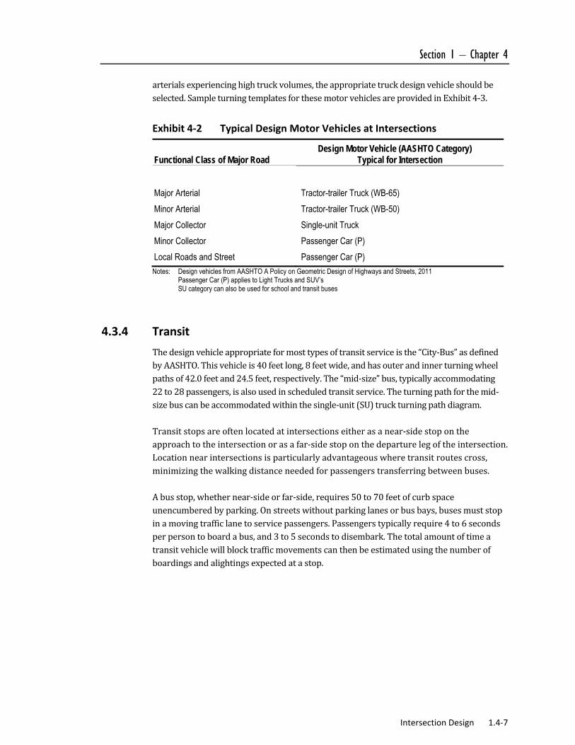
Thedesignmotorvehicleisthelargesttypeofvehicletypicallyexpectedtobeaccommodatedonthestreet.Atintersections,themostimportantattributeofdesignvehiclesistheirturningradius,whichinturninfluencesthepavementcornerradiusandthereforethesizeoftheintersection.Lanewidth,anotherfeaturerelatedtothedesignvehicle,hassomeimpactonintersectiondesign,butlessthanturningradius.Thedesignvehiclemayalsoaffectthechoiceoftrafficcontroldeviceandtheneedforauxiliarylanes.Thedesignvehicleforintersectionsisthelargerofthedesignvehiclesselectedfortheintersectingstreets.Forexample,attheintersectionofaminorarterialandalocalstreet,theappropriatedesignvehiclefortheintersectionisthatrequiredbytheminorarterial(i.e.,“larger”street).Exhibit4‐2,TypicalDesignVehiclesatIntersections,providesgeneralguidanceforselectingdesignvehiclesappropriateforintersectiondesignunderconditionsofnormaltrafficcomposition.Atlocationswherecollectorsintersectwith
Section 1 – Chapter 4
Intersection Design 1.4‐7
arterialsexperiencinghightruckvolumes,theappropriatetruckdesignvehicleshouldbeselected.SampleturningtemplatesforthesemotorvehiclesareprovidedinExhibit4‐3.
Exhibit 4‐2 Typical Design Motor Vehicles at Intersections
Functional Class of Major Road Design Motor Vehicle (AASHTO Category)
Typical for Intersection
Major Arterial Tractor-trailer Truck (WB-65)
Minor Arterial Tractor-trailer Truck (WB-50)
Major Collector Single-unit Truck
Minor Collector Passenger Car (P)
Local Roads and Street Passenger Car (P)
Notes: Design vehicles from AASHTO A Policy on Geometric Design of Highways and Streets, 2011 Passenger Car (P) applies to Light Trucks and SUV’s SU category can also be used for school and transit buses
4.3.4 Transit
Thedesignvehicleappropriateformosttypesoftransitserviceisthe“City‐Bus”asdefinedbyAASHTO.Thisvehicleis40feetlong,8feetwide,andhasouterandinnerturningwheelpathsof42.0feetand24.5feet,respectively.The“mid‐size”bus,typicallyaccommodating22to28passengers,isalsousedinscheduledtransitservice.Theturningpathforthemid‐sizebuscanbeaccommodatedwithinthesingle‐unit(SU)truckturningpathdiagram.Transitstopsareoftenlocatedatintersectionseitherasanear‐sidestopontheapproachtotheintersectionorasafar‐sidestoponthedeparturelegoftheintersection.Locationnearintersectionsisparticularlyadvantageouswheretransitroutescross,minimizingthewalkingdistanceneededforpassengerstransferringbetweenbuses.Abusstop,whethernear‐sideorfar‐side,requires50to70feetofcurbspaceunencumberedbyparking.Onstreetswithoutparkinglanesorbusbays,busesmuststopinamovingtrafficlanetoservicepassengers.Passengerstypicallyrequire4to6secondsperpersontoboardabus,and3to5secondstodisembark.Thetotalamountoftimeatransitvehiclewillblocktrafficmovementscanthenbeestimatedusingthenumberofboardingsandalightingsexpectedatastop.

1.4‐8 Intersection Design DRAFT
Exhibit 4‐3 Sample Vehicle Turning Template
Passenger Car (P) Single Unit Truck (SU-12 [SU-40])
Intermediate Semi-Trailer (WB-12 [WB-40]) Transit Bus (CITY BUS)
Source: Adapted from A Policy on the Geometric Design of Streets and Highways, AASHTO, 2011.
Note: Not to scale

Section 1 – Chapter 4
Intersection Design 1.4‐9
4.4 Intersection Types and Configurations
Intersectionscanbecategorizedintofourmajortypes,asillustratedinExhibit4‐4,IntersectionTypes.
4.4.1 Simple Intersections
Simpleintersectionsmaintainthestreet’stypicalcross‐sectionandnumberoflanesthroughouttheintersection,onboththemajorandminorstreets.Simpleintersectionsarebest‐suitedtolocationswhereauxiliary(turning)lanesarenotneededtoachievethedesiredlevel‐of‐service,orareinfeasibleduetonearbyconstraints.Generally,simpleintersectionsprovidetheminimumcrossingdistancesforpedestriansandarecommoninlow‐volumelocations.
4.4.2 Flared Intersections
Flaredintersectionsexpandthecross‐sectionofthestreet(main,crossorboth).Theflaringisoftendonetoaccommodatealeft‐turnlane,sothatleft‐turningbicyclesandmotorvehiclesareremovedfromthethrough‐trafficstreamtoincreasecapacityathigh‐volumelocations,andsafetyonhigherspeedstreets.Right‐turnlanes,lessfrequentlyusedthanleft‐turnlanes,areusuallyaresponsetolargevolumesofrightturns.Intersectionsmaybeflaredtoaccommodateanadditionalthroughlaneaswell.Thisapproachiseffectiveinincreasingcapacityatisolatedruralorsuburbansettingsinwhichlengthywideningbeyondtheintersectionis:notneededtoachievethedesiredlevel‐of‐service;notfeasibleduetonearbyconstraints;or,notdesirablewithinthecontextoftheproject.Intersectionapproachescanbeflaredslightly,notenoughforadditionalapproachlanesbutsimplytoeasethevehicleturningmovementapproachingordepartingtheintersection.Thistypeofflaringhasbenefitstobicycleandmotorvehicularflowsincehigherspeedturningmovementsattheintersectionarepossibleandencroachmentbylargerturningvehiclesintoothervehiclepathsisreduced.However,addingflaretoanintersectionincreasesthepedestriancrossingdistanceandtime.

1.4‐10 Intersection Design DRAFT
Exhibit 4‐4 Intersection Types
Source: Adapted from A Policy on the Geometric Design of Streets and Highways, AASHTO, 2011. Chapter 3 Elements of Design

Section 1 – Chapter 4
Intersection Design 1.4‐11
4.4.3 Channelized Intersections
Channelizedintersectionsusepavementmarkingsorraisedislandstodesignatetheintendedvehiclepaths.Themostfrequentuseisforrightturns,particularlywhenaccompaniedbyanauxiliaryright‐turnlane.Atskewedintersections,channelizationislandsareoftenusedtodelineaterightturns,evenintheabsenceofauxiliaryrightturnlanes.Atintersectionslocatedonacurve,divisionalislandscanhelpdirectdriverstoandthroughtheintersection.Atlargeintersections,shortmedianislandscanbeusedeffectivelyforpedestrianrefuge.Channelizationislandsarealsousedinsupportofleft‐turnlanes,formingtheendsofthetaperapproachingtheturnbay,andoftenthenarrowdivisionalislandextendingtotheintersection.At“T”‐typeintersections,achannelizationislandcanguideoncomingtraffictotherightoftheleft‐turnlane.Channelizedintersectionsareusuallylargeand,therefore,requirelongpedestriancrosswalks.However,thechannelizationislandscaneffectivelyreducethecrosswalkdistanceinwhichpedestriansareexposedtomovingmotorvehicles.Thedesignofchannelizedintersectionsneedstoensurethattheneedsofpedestriansareconsidered,includingpedestriancurbcutrampsor“cut‐throughs”thatallowwheelchairusersthesamesafeharborasotherpedestriansonchannelizationislands.
4.4.4 Roundabouts
Theroundaboutisachannelizedintersectionwithone‐waytrafficflowcirculatingaroundacentralisland.Alltraffic—throughaswellasturning—entersthisone‐wayflow.Althoughusuallycircularinshape,thecentralislandofaroundaboutcanbeovalorirregularlyshaped.Roundaboutscanbeappropriatedesignalternativetobothstop‐controlledandsignal‐controlledintersections,astheyhavefewerconflictpointsthantraditionalintersections(eightversus32,respectively).Atintersectionsoftwo‐lanestreets,roundaboutscanusuallyfunctionwithasinglecirculatinglane,makingitpossibletofitthemintomostsettings.Roundaboutsdifferfrom“rotaries”inthefollowingrespects:
Size—Singlelaneroundaboutshaveanoutsidediameterbetween80and140feet,whereas,rotariesaretypicallymuchlargerwithdiametersaslargeas650feet.
Speed—Thesmalldiameterofroundaboutslimitscirculatingvehiclespeedsto10to25milesperhour,whereas,circulatingspeedsatrotariesistypically30to40milesperhour.

1.4‐12 Intersection Design DRAFT
Capacity—Theslowercirculatingspeedsatroundaboutsallowenteringvehiclestoacceptsmallergapsinthecirculatingtrafficflow,meaningmoregapsareavailable,increasingthevolumeoftrafficprocessed.Atrotaries,vehiclesneedlargergapsinthecirculatingtrafficflowreducingthevolumeoftrafficprocessed.
Safety—Theslowerspeedsatroundaboutsnotonlyreducetheseverityofcrashes,butminimizesthetotalnumberofallcrashes,whereas,rotariestypicallyseehighnumbersofcrasheswithagreaterseverity.
Roundaboutsarealsoconsideredastraffic‐calmingdevicesinsomelocationssincealltrafficisslowedtothedesignspeedoftheone‐waycirculatingroadway.Thisisincontrastwithapplicationoftwo‐waystopcontrol,wherethemajorstreetisnotslowedbytheintersection,orall‐waystopcontrolwherealltrafficisrequiredtostop.Roundaboutscanalsobeconsideredforretrofitofexistingrotaries;however,incaseswithveryhightrafficvolumes,trafficsignalcontrolmaybemoresuitable.
4.4.5 Typical Intersection Configurations
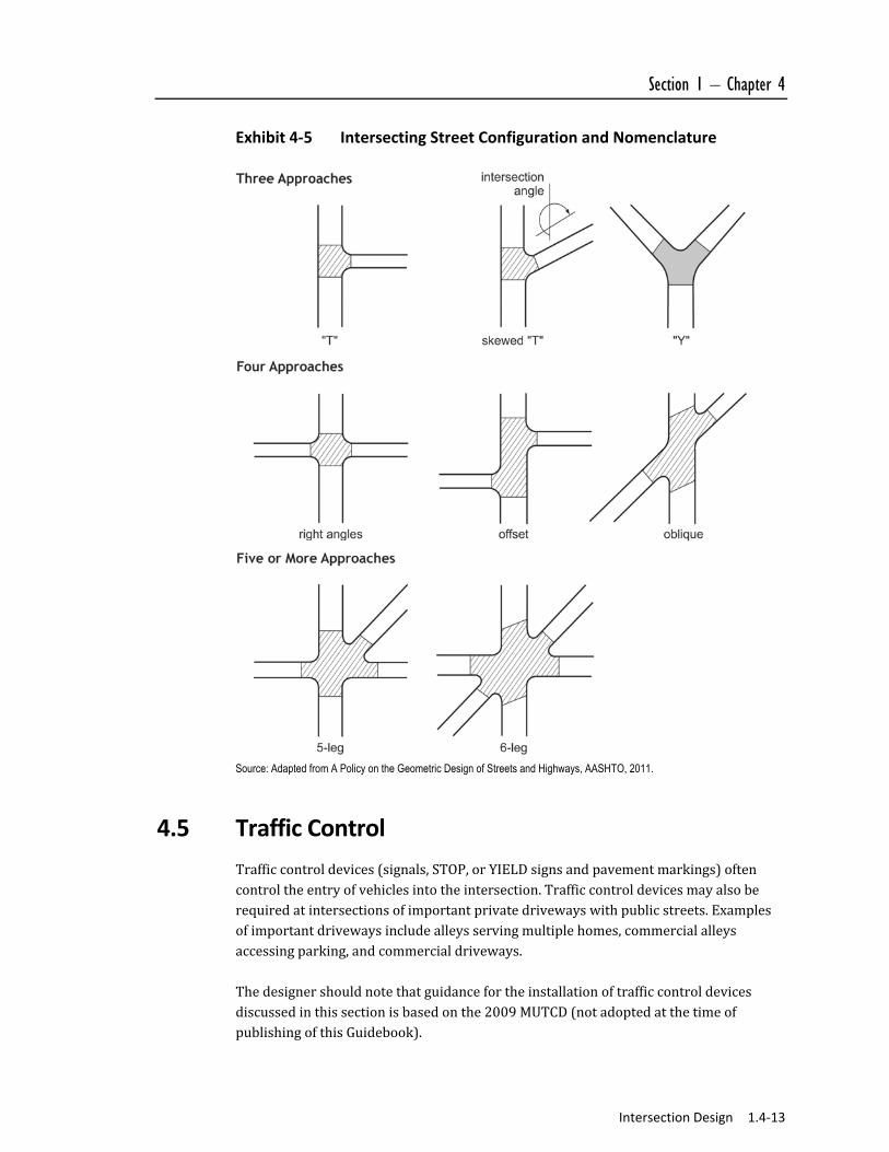
Mostintersectionshavethreeorfourlegs,butmulti‐legintersections(five‐andevensix‐legintersections)arenotunusual.ExamplesofintersectionconfigurationsfrequentlyencounteredbythedesignerareshowninExhibit4‐5.Ideally,streetsinthree‐legandfour‐legintersectionscrossatrightanglesornearlyso.However,skewedapproachesarearegularfeatureofintersectiondesign.Whenskewanglesarelessthan60degrees,thedesignershouldevaluateintersectionmodificationstoreducetheskew.
Section 1 – Chapter 4
Intersection Design 1.4‐13
Exhibit 4‐5 Intersecting Street Configuration and Nomenclature
Source: Adapted from A Policy on the Geometric Design of Streets and Highways, AASHTO, 2011.
4.5 Traffic Control
Trafficcontroldevices(signals,STOP,orYIELDsignsandpavementmarkings)oftencontroltheentryofvehiclesintotheintersection.Trafficcontroldevicesmayalsoberequiredatintersectionsofimportantprivatedrivewayswithpublicstreets.Examplesofimportantdrivewaysincludealleysservingmultiplehomes,commercialalleysaccessingparking,andcommercialdriveways.Thedesignershouldnotethatguidancefortheinstallationoftrafficcontroldevicesdiscussedinthissectionisbasedonthe2009MUTCD(notadoptedatthetimeofpublishingofthisGuidebook).

1.4‐14 Intersection Design DRAFT
4.5.1 Traffic Control Measures
Potentiallyconflictingflows(vehicle‐to‐vehicleorvehicle‐to‐non‐vehicle)areaninherentfeatureofintersections.Atmostintersections,therefore,trafficcontrolmeasuresarenecessarytoassigntherightofway.Typesofintersectiontrafficcontrolinclude:
Wheresufficientvisibilityisprovidedinlowvolumesituations,someintersectionsoperateeffectivelywithoutformalizedtrafficcontrol.Inthesecases,normalrightofwayrulesapply.
Yieldcontrol,withtrafficcontrolledby“YIELD”signs(sometimesaccompaniedbypavementmarkings)ontheminorstreetapproaches.Majorstreettrafficisnotcontrolled.
All‐wayyieldcontrolonroundabouts.
Two‐waystopcontrol,withtrafficcontrolledby“STOP”signorbeaconsontheminorstreetapproaches.Majorstreettrafficisnotcontrolled.Theterm“two‐waystopcontrol”canalsobeappliedto“T”intersections,eventhoughtheremaybeonlyoneapproachunderstopcontrol.STOPcontrolshouldnotbeusedforspeedreduction.
All‐waystopcontrol,withtrafficonallapproachescontrolledbySTOPsignsorSTOPbeacons.All‐waystopcontrolcanalsobeatemporarycontrolatintersectionsforwhichtrafficsignalsarewarrantedbutnotyetinstalled.
Trafficsignals,controllingtrafficonallapproaches.
Flashingwarningbeaconsonsomeorallapproaches.
Generally,thepreferredtypeoftrafficcontrolcorrelatesmostcloselywithsafetyconcernsandvolumeofmotorvehicles,bicyclesandpedestrians.Forintersectionswithlowervolumes,STOPorYIELDcontrolonthecross(minor)streetisthemostfrequentlyusedformofvehiculartrafficcontrol.
4.5.1.1 Stop and Yield Control Warrants
PartTwooftheMUTCDshouldbeconsultedforguidanceonappropriateSTOPandYIELDsignusageandplacement.Ingeneral,STOPorYIELDsignscouldbeusedifoneormoreofthefollowingexist:
Anintersectionofalessimportantroadwithamainroadwhereapplicationofthenormalrightofwayrulewouldnotbeexpectedtoprovidereasonablecompliancewiththelaw;
Astreetenteringadesignatedthroughhighwayorstreet;and/or
Anunsignalizedintersectioninasignalizedarea.

Section 1 – Chapter 4
Intersection Design 1.4‐15
Inaddition,theuseofSTOPorYIELDsignsshouldbeconsideredattheintersectionoftwominorstreetsorlocalroadswheretheintersectionhasmorethanthreeapproachesandwhereoneormoreofthefollowingconditionsexist:
Thecombinedvehicular,bicycle,andpedestrianvolumeenteringtheintersectionfromallapproachesaveragesmorethan2,000unitsperday;
Theabilitytoseeconflictingtrafficonanapproachisnotsufficienttoallowaroadusertostoporyieldincompliancewiththenormalright‐of‐wayruleifsuchstoppingoryieldingisnecessary;and/or
Crashrecordsindicatethatfiveormorecrashesthatinvolvethefailuretoyieldtheright‐of‐wayattheintersectionunderthenormalright‐of‐wayrulehavebeenreportedwithina3‐yearperiod,orthatthreeormoresuchcrasheshavebeenreportedwithina2‐yearperiod.
Atintersectionswhereafullstopisnotnecessaryatalltimes,considerationshouldbegiventousinglessrestrictivemeasures,suchasYIELDsigns.YIELDsignscouldbeinstalled:
Ontheapproachestoathroughstreetorhighwaywhereconditionsaresuchthatafullstopisnotalwaysrequired.
Atthesecondcrossroadofadividedhighway,wherethemedianwidthattheintersectionis30feetorgreater.Inthiscase,aSTOPorYIELDsignmaybeinstalledattheentrancetothefirstroadwayofadividedhighway,andaYIELDsignmaybeinstalledattheentrancetothesecondroadway.
Forachannelizedturnlanethatisseparatedfromtheadjacenttravellanesbyanisland,eveniftheadjacentlanesattheintersectionarecontrolledbyahighwaytrafficcontrolsignalorbyaSTOPsign.
AtanintersectionwhereaspecialproblemexistsandwhereengineeringjudgmentindicatestheproblemtobesusceptibletocorrectionbytheuseoftheYIELDsign.
Facingtheenteringroadwayforamerge‐typemovementifengineeringjudgmentindicatesthatcontrolisneededbecauseaccelerationgeometryand/orsightdistanceisnotadequateformergingtrafficoperation.
4.5.1.2 Multiway STOP Control
MultiwaySTOPcontrolcanbeusefulasasafetymeasureatintersectionsifcertaintrafficconditionsexist.Safetyconcernsassociatedwithmultiwaystopsincludepedestrians,bicyclists,andallroadusersexpectingotherroaduserstostop.MultiwaySTOPcontrolisusedwherethevolumeoftrafficontheintersectionroadsinapproximatelyequal.ThefollowingcriteriashouldbeconsideredformultiwaySTOPsigninstallation.

1.4‐16 Intersection Design DRAFT
Wheretrafficcontrolsignalsarejustified,themultiwaySTOPisaninterim
measurethatcanbeinstalledquicklytocontroltrafficwhilearrangementsarebeingmadefortheinstallationofthetrafficcontrolsignal;
Fiveormorereportedcrashesina12‐monthperiodthataresusceptibletocorrectionbyamultiwaySTOPinstallation.Suchcrashesincluderight‐turnandleft‐turncollisionsaswellasright‐anglecollisions;
Minimumvolumes:
Thevehicularvolumeenteringtheintersectionfromthemajorstreetapproaches(totalofbothapproaches)averagesatleast300vehiclesperhourforanyeighthoursofanaverageday,and
Thecombinedvehicular,pedestrian,andbicyclevolumeenteringtheintersectionfromtheminorstreetapproaches(totalofbothapproaches)averagesatleast200unitsperhourforthesameeighthours,withanaveragedelaytominorstreetvehiculartrafficofatleast30secondspervehicleduringthehighesthour,but
Ifthe85thpercentileapproachspeedofthemajorstreettrafficexceeds40mph,theminimumvehicularvolumewarrantsare70percentoftheabovevalues.
Wherenosinglecriterionissatisfied,butwherethesecondandthirdcriteriaareallsatisfiedto80percentoftheminimumvalues.The85thpercentilespeedcriterionisexcludedfromthiscondition.
Athighercombinationsofmajorstreetandminorstreetvolume,trafficsignalsbecomethecommontrafficcontrolmeasure.Roundaboutsshouldalsobeconsideredinthesesituations.Thedecisiontousetrafficsignalsshouldfollowthe“signalwarrants”specifiedintheMUTCD.Thesewarrantsaresummarizedinthefollowingsection.
4.5.1.3 Traffic Signal Warrants
TrafficsignalsshouldonlybeconsideredwheretheintersectionmeetswarrantsintheManualonUniformTrafficControlDevices(MUTCD).Wherewarrantedandproperlyinstalled,trafficsignalscanprovideforanorderlymovementoftraffic.Comparedtostopcontrol,signalscanincreasethetrafficcapacityoftheintersection,reducefrequencyandseverityofcrashes,particularlyright‐anglecrashes,andinterruptheavytrafficflowtopermitothermotorvehicles,pedestriansandbicyclestocrossthestreet.Unwarrantedorpoorlytimedtrafficsignalscanhavenegativeimpacts,includingexcessivedelaytovehicularandpedestriantraffic,disrespectfortrafficcontroldevices
The satisfaction of a traffic signal
warrant or warrants shall not, in
itself, require the installation of a
traffic control signal. The traffic
signal warrant analysis provides
guidance as to locations where
signals would not be appropriate
and locations where they could
be considered further.
Section 1 – Chapter 4
Intersection Design 1.4‐17
ingeneral,increased“cutthrough”trafficoninappropriateroutes,andincreasedfrequencyofcrashes.KeyfeaturesoftheMUTCDwarrantsare:
Warrant1:8‐hourvehicularvolume,metby500to600vehiclesperhouronthemajorstreet(bothdirections,two‐fourlanesrespectively)and150to200vehiclesontheminorstreet(majordirection,one‐twolanesrespectively),foranycombinationof8hoursdaily.Avariation(“interruptionofcontinuoustraffic”)warrantismetwith750to900vehicleshourlyonmajorstreet(two‐fourlanes,bothdirections),and75to100vehicleshourly(majordirection,one‐twolanes),ontheminorstreet.Thesevolumescanbereducedundercertaincircumstances(seePart4oftheMUTCDfordetails).
Warrant2:four‐hourvehicularvolume,metwhentheplottedpointsforeachofanyfourhoursrepresentingthevehiclesperhouronthemajorstreet(totalofbothapproaches)andthecorrespondingvehiclesperhouronthehigher‐volumeminor‐streetapproach(onedirectiononly)allfallabovetheapplicablecurveintheMUTCD.
Warrant3:peakhour,metwhentheplottedpointsforonehourrepresentingthevehiclesperhouronthemajorstreet(totalofbothapproaches)andthecorrespondingvehiclesperhouronthehigher‐volumeminor‐streetapproach(onedirectiononly)fallabovetheapplicablecurveintheMUTCD.
Warrant4:pedestrianvolume,metwhentheplottedpointsforeachofanyfourhoursofthevehiclesperhouronthemajorstreet(totalofbothapproaches)andthecorrespondingpedestriansperhourcrossingthemajorstreet(totalofallcrossings)allfallabovethecurveintheMUTCDforthePedestrianFourHourWarrant;orwhentheplottedpointsforonehourofthevehiclesperhouronthemajorstreet(totalofbothapproaches)andthecorrespondingpedestriansperhourcrossingthemajorstreet(totalofallcrossings)allfallabovethecurveintheMUTCDforthePedestrianPeakHourWarrant.
Warrant5:schoolcrossing,metwithaminimumof20studentscrossinginthehighestcrossinghour,andlessthanoneacceptablegapinthetrafficstreamperminuteduringthehighestcrossinghour.Engineeringjudgmentandattentiontootherremedies(suchascrossingguards,improvedsignage,andcrossingislands)arestronglyrecommended.
Warrant6:coordinatedtrafficsignalsystem,whereexistingtrafficsignalspacingdoesnotprovidethenecessarydegreeofplatooning(grouping)oftraffic,asneededtoprovideaprogressiveoperation.
Warrant7:crashexperience,metwhencrashdataindicatesaproblemremediablebytrafficsignalinstallation.
Warrant8:roadwaynetwork,metwhenthestreethasimportanceasaprincipalroadwaynetworkorisdesignatedasamajorrouteonanofficialplan.
Warrant9:intersectionnearagradecrossing,metwhenagradecrossingexistsonanapproachcontrolledbyaSTOPorYIELDsignandthetrackis

1.4‐18 Intersection Design DRAFT
within140feetofthestoplineoryieldlineontheapproach;andwhenduringthehighesttrafficvolumehourduringwhichrailtrafficusesthecrossing,theplottedpointrepresentingthevehiclesperhouronthemajorstreet(totalofbothapproaches)andthecorrespondingvehiclesperhourontheminor‐streetapproachthatcrossesthetrack(onedirectiononly,approachingtheintersection)fallsabovetheapplicablecurveintheMUTCD.
Aspartoftheintersectiondesignprocess,thedetailedwarrants,aspresentedintheManualonUniformTrafficControlDevices,shouldbefollowed.Evenifwarrantsaremet,asignalshouldbeinstalledonlyifitisdeterminedtobethemostappropriatetrafficcontrolbasedonthecontextoftheintersection,assignalsdonotaddcapacitytoanintersection,theyareintendedtoprovideorder.Inmanyinstances,trafficsignalinstallationwillrequiresomewidening.
4.5.1.4 Pedestrian Travel at Traffic Signals
Trafficsignaldesignshouldencompassthefollowingprinciplesforaccommodatingpedestrians:
Ingeneral,theWALKindicationshouldbeconcurrentwiththetrafficmovingontheparallelapproach.ItshouldbenotedthatConnDOTdoesnotutilizeconcurrentpedestriansignalphasingatStateownedandmaintainedsignalizedintersections.
TimingofpedestrianintervalsshouldbeinaccordancewithMUTCDandADArequirements.
Pedestriansshouldbegiventhelongestpossiblewalktime,whilemaintainingbalancebetweenmotorvehicleflowandpedestriandelay.Inmostcases,theWALKintervalshouldincludeallofthetimeinthevehiclegreenphase,exceptfortherequiredclearanceinterval.Althoughnotpreferred,theminimumlengthfortheWALKintervalonapedestriansignalindicationis7seconds,longenoughforapedestriantostepoffthecurbandbegincrossing.Insomelimitedcircumstances,wherepedestrianvolumeissmall,walkintervalsasshortas4secondsmaybeused.
Signalsshouldbetimedtoaccommodatetheaveragewalkingspeedsofthetypeofpedestrianthatpredominantlyusestheintersection.(Thelengthoftheclearanceintervaliscalculatedbasedoncrossingtheentirestreetfromcurbramptocurbrampwithanassumedcrossingspeedof3.5feetpersecond).Inareaswhereasignificantportionofexpectedpedestriansareolderorhavedisabilities,awalkingspeedoflessthan3.5feetpersecondshouldbeconsideredindeterminingthepedestrianclearancetime.
Signalcyclesshouldbeasshortaspossible.Shortsignalcyclesreducedelay,andthereforeimprovelevelofserviceforpedestrians,bicyclistsandmotorvehiclesalike.

Section 1 – Chapter 4
Intersection Design 1.4‐19
Simpletwo‐phasesignalsminimizepedestrianwaitingtimeandarethereforepreferableforpedestrianservice.Insomecases,simpletwo‐phasesignalsalsoprovidethebestserviceformotorvehicletraffic.
Leadingpedestrianintervals(LPI)givepedestriansanadvanceWALKsignalbeforethemotoristsgetaconcurrentgreensignal,givingthepedestrianseveralsecondstostartinthecrosswalk.Thismakespedestriansmorevisibletomotorvehiclesandallowspedestrianstoinitiatetheircrossingwithoutconflictwithothertraffic.
Goodprogressionformotorvehiclesthroughaseriesofsignalscanbeobtainedoverawiderangeofvehiclespeeds.Inareaswithhighvolumesofpedestrians,alowbutwell‐coordinatedvehicleprogressionspeed(20‐30mph)canbeusedwithlittleornonegativeimpactonvehicularflow.
Pedestrianphasesincorporatedintoeachsignalcycle,ratherthanon‐demandthroughacallbutton,maybepreferableforsomeconditions.
Callbuttonuseshouldbelimitedtoonlythoselocationswithtraffic‐actuatedsignals(i.e.,wherethesignaldoesnotcycleintheabsenceofminorstreettraffic).
Wherecallbuttonsareused,anotificationsignshouldbeprovided.
Pedestriancallbuttonactuationshouldprovideatimelyresponse,particularlyatisolatedsignals(i.e.,notinaprogressionsequence),atmid‐blockcrossings,andduringlow‐trafficperiods(night,forexample).
Atfour‐wayintersections,curbextensionscouldbeprovidedtodecreasethepedestriancrossinglength.
Pedestriancallbuttonsandthesignalstheyactivateshouldbemaintainedingoodrepair.Thisrequiresreliableandpredictablebuttonoperation,functionalsignaldisplays,andthecorrectorientationofpedestriansignalheads.
TheMUTCDrequiresthatallpedestriansignalheadsusedatcrosswalkswherethepedestrianchangeintervalismorethan7secondsshallincludeapedestrianchangeintervalcountdowndisplayinordertoinformpedestriansofthenumberofsecondsremaininginthepedestrianchangeinterval.Thecountdownishelpfultopedestriansbyprovidingtheexactamountofcrossingtimeremaining,therebyallowingthemtomaketheirowninformedjudgmentoninitiatingacrossing,ratherthansimplyfollowingtheWALK/DON’TWALKphases.GuidelinesforthedisplayandtimingofcountdownindicatorsareprovidedintheManualonUniformTrafficControlDevices.Accessiblepedestriansignalsanddetectorsprovideinformationinnon‐visualformatssuchasaudibletones,speechmessages,and/orvibratingsurfaces.GuidelinesfortheinstallationofsuchfeaturesareprovidedintheManualonUniformTrafficControlDevices.
1.4‐20 Intersection Design DRAFT
Locating Pedestrian Call Buttons
Pedestriansignalcallbuttonsareusedtoinitiateapedestriancrossingphaseattrafficsignals.Whereneeded,pedestriancallbuttonsshouldbelocatedtomeetthefollowingcriteria:
Theclosestcallbuttontoacrosswalkshouldcallthepedestriansignalforthatcrosswalk.
Anarrowindicatorshouldshowwhichcrosswalkthebuttonwillaffect.
Thecallbuttonshouldalignwiththecrosswalkandbevisibletoapedestrianfacingthecrosswalk,unlessspaceconstraintsdictateanotherbuttonplacement.
Pedestrianactuatedcallbuttonsshouldbeplacedinlocationsthatareeasytoreach,atapproximately3.5feetbutnomorethanfourfeetabovethesidewalk.
Accessible Pedestrian Signal Systems
Atsignalizedintersections,peoplewithvisionimpairmentstypicallyrelyonthenoiseoftrafficalongsidethemasacuetobegincrossing.Theeffectivenessofthistechniqueiscompromisedbyvariousfactors,includingincreasinglyquietcars,permittedrightturnsonred,pedestrianactuatedsignalsandwidestreets.Further,lowtrafficvolumesmaymakeitdifficulttodiscernsignalphasechanges.Technologiesareavailablethatenableaudibleandvibratingsignalstobeincorporatedintopedestrianwalksignalsystems.TheManualonUniformTrafficControlDevicesoffersguidelinesontheuseofaccessiblepedestriansignals.TheFederalAccessBoard’sreviseddraftversion(2005)oftheADAAccessibilityGuidelinesforPublicRight‐of‐Wayrequirestheuseofaudiblesignalswithallpedestriansignals.
4.6 Intersection Capacity and Quality of Service
The“capacity”ofanintersectionforanyofitsusers(motorvehicles,pedestrians,bicyclists,transitvehicles)isthemaximumrateofflowofthatusertypethatcanbeaccommodatedthroughtheintersection.Typically,capacityisdefinedforaparticularusergroupwithoutotherusergroupspresent.Thus,forexample,motorvehicularcapacityisstatedintermsofvehiclesperhour,undertheassumptionthatnootherflows(pedestrians,bicycles)aredetractingfromsuchcapacity.Multimodalcapacityistheaggregatecapacityoftheintersectionforallusersoftheintersection.Insomecases,themaximummultimodalcapacitymaybeobtainedwhilesomeindividualuserflowsareatlessthantheirindividualoptimumcapacity.Qualityofservicecanbedefinedinacoupleofdifferentways.Onemeasureofeffectivenessthatcanbeusedtounderstandthequalityoftransportationatanintersectionforagivenmodeisthecontroldelayencounteredbytheuseratthe

Section 1 – Chapter 4
Intersection Design 1.4‐21
intersection.Controldelay,aresultoftrafficcontroldevicesneededtoallocatethepotentiallyconflictingflowsattheintersection,reflectsthedifferencebetweentraveltimethroughtheintersectionatfreeflowversustraveltimeundertheencounteredconditionsoftrafficcontrol.Fordrivers,controldelayconsistsoftime“lost”(fromfree‐flowtime)duetodeceleration,waitingatsignals,STOPorYIELDsigns,waitingandadvancingthroughaqueueoftraffic,andacceleratingbacktofree‐flowspeed.Forpedestriansandbicyclists,decelerationandaccelerationtimesareinsignificant,andcontroldelayislargelythetimespentwaitingatsignals,STOP,orYIELDsigns.Anotherwayistodefinethequalityofserviceistodeterminethe“Levelofservice”whichisdefinedbytheHighwayCapacityManual,foreachtypeofintersectionuser.Foreachuser,levelofserviceiscorrelatedtodifferentfactorsbecauseeachmodehasuniqueissuesthatimpactthequalityofitsusers.Forautomobileslevelofserviceisgovernedbycontroldelay.Forbicyclesandpedestriansthelevelofserviceisdeterminedbyseveralfactorsthatdescribetheconditionsofthebicycleandpedestriansfacilities,theimpactsofmotorvehicletrafficonthesemodes,andthecharacteristicsofbicycleandpedestriantraffic.Eachoftheseanalysesisdescribedfurtherinsection4.6.2anddetaileddiscussionsoftheanalysesmethodologyarepresentedintheHighwayCapacityManual.Levelsofserviceanddelayaresomewhatcorrelatedtocapacityinthatlevelsofservicedeclinedascapacityisapproached.
4.6.1 Capacity
“Capacity”(themaximumpossibleflow)differsimportantlyfrom“servicevolumes”(flowsassociatedwiththequalityofflow,typicallystatedas“LevelofService”or“LOS”).Thesetwotermsarediscussed,forpedestrian,bicycle,andmotorvehicleflow,inthefollowingsections.
4.6.1.1 Pedestrian Flow Capacity
Unlikemotorvehiclesandbicycles,pedestrianfacilities(sidewalksandcrosswalks)donothaveadefaultcapacityforanalysispurposes.Onemeasurethatcanprovideinsightintothequalityandconditionofpedestrianfacilitiesisthepedestrianspacemeasuredinsquarefeetperpedestrian(ft2/p).TheHighwayCapacityManualsuggeststhatoncepedestrianspacefallsbelow15ft2/p,pedestrianspeedsbegintofallandtheabilityforpedestrianstomoveontheirdesiredpathbecomesrestricted.MethodsforcalculatingpedestrianspaceforsidewalksandcrosswalksarepresentedintheHighwayCapacityManual.Atsignalizedintersections,eachapproachwillaccommodatepedestriancrossingsfor10to20percentofthetime,reflectingtheintervalsthatpedestrianscanbegintocrosswithassuranceofcompletingtheircrossingwhiletrafficisstoppedfortheirapproach.Atunsignalizedlocations,thetimeavailableforpedestrianflowisdictatedbymotorvehiclevolumeandlengthofthecrossing.Thesetwofactors,whichgovernthenumber
1.4‐22 Intersection Design DRAFT
of“gaps”inthemotorvehiclestreamavailableforsafepedestriancrossing,mustbemeasuredon‐sitetoestablishthepedestrianflowcapacityofanunsignalizedintersection.ThesignalwarrantsintheMUTCDofferguidanceoncombinationsofmotorvehicleandpedestrianvolumesthatmayjustifyasignal,andthereforereflectthepedestriancapacityofunsignalizedintersections.
4.6.1.2 Bicycle Flow Capacity
Abicyclelane(4‐6feetinwidth)can,withuninterruptedflow,carryavolumeofaround2,000bicyclesperhourinonedirection.Atsignalizedintersections,bicyclelanesreceivethesamegreensignaltimeasmotorvehicles,typically20‐35percentofthetotaltime.Thehourlycapacityofabicyclelane,atasignalizedintersection,istherefore400to700bicyclesperhour.Atsignalizedintersectionswithoutbicyclelanes,bicyclesarepartoftheapproachingvehiculartrafficstream.Thecombinedvehicularcapacity(motorvehiclesaswellasbicycles)isestablishedasdefinedinSection4.6.1.3.Atunsignalizedintersectionswithbicyclelanesonthemajorstreet,thebicycleflowcapacityistheuninterruptedflowvolumeof2,000bicyclesperhour.FortheSTOP‐controlled(minorstreet)approach,theflowcapacityforbicycles,whetherinbicyclelanesornot,isgovernedbythespeed,motorvehiclevolume,andnumberoflanesofmajorstreettraffic.Thesefactorsrequiremeasurementon‐sitetoestablishthebicycleflowcapacityofSTOPcontrolledapproaches.
4.6.1.3 Motor Vehicle Capacity
Atunsignalizedintersections,motorizedvehiclecapacityisgovernedbytheabilityofmotorvehicles(ontheminorstreet)underSTOPcontrolorYIELDcontroltoenterorcrossthestreamofmovingmotorvehiclesonthemajorstreet.Thiscapacityisreachedasthenumberofmotorvehiclesonbothmajorstreetapproaches,plusthenumberonthebusiestminorstreetapproachtotals1,200motorvehiclesinasinglepeakhour,ortotals900motorvehicleshourlyoveracontinuous4‐hourperiod.Atthesepoints,enteringorcrossingthemajorstreetfromtheSTOPcontrolledorYIELDcontrolledminorstreetbecomesdifficultorimpossible.FurtherincreasesinintersectioncapacityatSTOPcontrolledorYIELDcontrolledintersectionscanbegainedbyreplacingstoporyieldcontrolwithsignalcontroloraroundabout.Trafficsignalwarrants1,2,and3discussedpreviouslyprovidedetailedguidanceonspecificcombinationsofmajorandminorstreetvolumesassociatedwiththetransitionfromSTOPcontrolorYIELDcontroltotrafficsignalcontrol.Atsignalizedintersections,motorvehiclecapacityisgovernedbythenumberoflanesapproachingtheintersection,thenumberofreceivinglanes,andtheamountofgreensignaltimegiventotheapproach.Thetotalgreentimeavailabledecreasesasmoresignalphasesandthereforemoreredandyellow“losttime”areincludedinthesignalsequences.
Section 1 – Chapter 4
Intersection Design 1.4‐23
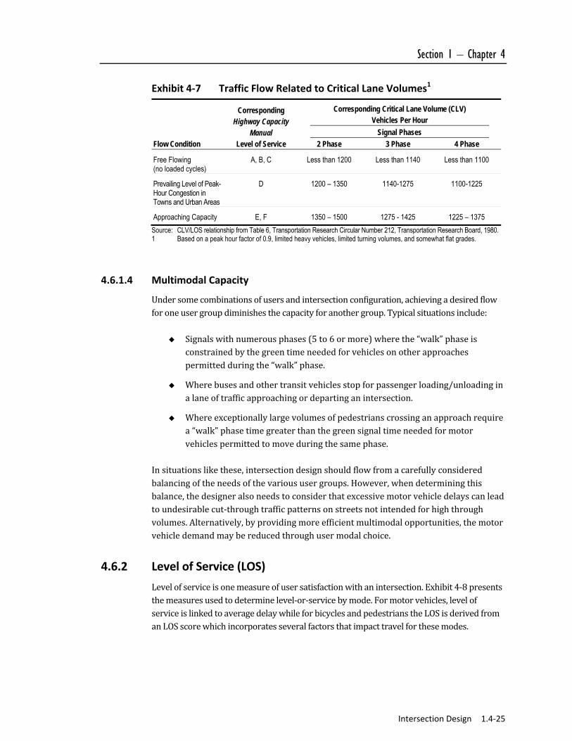
Asimplebutreliablemeasureofasignalizedintersection’scapacityisits“criticallanevolume”capacity(CLVcapacity),definedasthemaximumsumofconflictingmovementsthatcanbemovedthroughtheintersectionatagivenlevelofserviceasshowninExhibit4‐6.SignalizedintersectioncapacityisnearedastheCLVreaches1,500hourlymotorvehiclesforintersectionswithtwosignalphases(theminimumpossible)or1,375to1,425forintersectionswithmorethantwosignalphases.ThissimpleCLVmeasurecanbeusedforinitialassessmentofanintersection’scapacity,andalsoasareasonablenesscheckonproceduresintheHighwayCapacityManual.TherelationshipbetweenCLVcapacityandlevelofservice(describedinmoredetailinSection4.6.2)issummarizedinExhibit4‐7.Atroundabouts,motorvehiclecapacityisgovernedbytheabilityofenteringtraffictoenterthestreamofmotorvehiclesinthecirculatingroadway.Thiscapacityisnearedasthevehicularvolumeinthecirculatingroadway(singlelane)approaches1,800motorvehicleshourly.Atthispoint,enteringthestreamofcirculatingmotorvehicleswithintheroundaboutbecomesdifficultorimpossible.Atthisthreshold,additionallanesononeormoreapproachesandasecondcirculatinglaneshouldbeconsidered.

1.4‐24 Intersection Design DRAFT
Exhibit 4‐6 Computing Critical Lane Volume
Notes: Critical lane volume (CLV) is the sum of main street CLV plus the cross street CLV. The main street CLV is the greater of either: (A) eastbound through and right per lane + westbound left, or (B)
westbound through and right per lane + eastbound left. Similarly, the cross street CLV is the greater of either: (A) northbound through and right per lane + southbound left, or (B)
southbound through and right per lane + northbound left. Total intersection CLV = main street CLV + cross street CLV = 390 + 480 = 870. Source: Transportation Research Board, Circular Number 212, TRB 1980.
Section 1 – Chapter 4
Intersection Design 1.4‐25
Exhibit 4‐7 Traffic Flow Related to Critical Lane Volumes1
Flow Condition
Corresponding Highway Capacity
Manual Level of Service
Corresponding Critical Lane Volume (CLV) Vehicles Per Hour
Signal Phases
2 Phase 3 Phase 4 Phase
Free Flowing (no loaded cycles)
A, B, C Less than 1200 Less than 1140 Less than 1100
Prevailing Level of Peak-Hour Congestion in Towns and Urban Areas
D 1200 – 1350 1140-1275 1100-1225
Approaching Capacity E, F 1350 – 1500 1275 - 1425 1225 – 1375
Source: CLV/LOS relationship from Table 6, Transportation Research Circular Number 212, Transportation Research Board, 1980. 1 Based on a peak hour factor of 0.9, limited heavy vehicles, limited turning volumes, and somewhat flat grades.
4.6.1.4 Multimodal Capacity
Undersomecombinationsofusersandintersectionconfiguration,achievingadesiredflowforoneusergroupdiminishesthecapacityforanothergroup.Typicalsituationsinclude:
Signalswithnumerousphases(5to6ormore)wherethe“walk”phaseisconstrainedbythegreentimeneededforvehiclesonotherapproachespermittedduringthe“walk”phase.
Wherebusesandothertransitvehiclesstopforpassengerloading/unloadinginalaneoftrafficapproachingordepartinganintersection.
Whereexceptionallylargevolumesofpedestrianscrossinganapproachrequirea“walk”phasetimegreaterthanthegreensignaltimeneededformotorvehiclespermittedtomoveduringthesamephase.
Insituationslikethese,intersectiondesignshouldflowfromacarefullyconsideredbalancingoftheneedsofthevarioususergroups.However,whendeterminingthisbalance,thedesigneralsoneedstoconsiderthatexcessivemotorvehicledelayscanleadtoundesirablecut‐throughtrafficpatternsonstreetsnotintendedforhighthroughvolumes.Alternatively,byprovidingmoreefficientmultimodalopportunities,themotorvehicledemandmaybereducedthroughusermodalchoice.
4.6.2 Level of Service (LOS)
Levelofserviceisonemeasureofusersatisfactionwithanintersection.Exhibit4‐8presentsthemeasuresusedtodeterminelevel‐or‐servicebymode.Formotorvehicles,levelofserviceislinkedtoaveragedelaywhileforbicyclesandpedestrianstheLOSisderivedfromanLOSscorewhichincorporatesseveralfactorsthatimpacttravelforthesemodes.

1.4‐26 Intersection Design DRAFT
Exhibit 4‐8 Measures to Determine Level of Service by Mode
Intersection Type Mode
Pedestrian Bicycle Automobile
Signalized LOS score LOS score Delay
Unsignalized Delay N/A Delay and v/c ratio
Roundabout Delay N/A Delay and v/c ratio Source: Highway Capacity Manual, 2010
4.6.2.1 Pedestrian Level of Service
PedestrianlevelofserviceisdefinedbythepedestrianLOSscoreordelay,dependingonintersectiontype.Exhibit4‐8summarizespedestrianlevelofserviceforintersections.
Exhibit 4‐8 Pedestrian Level‐of‐Service (LOS) Criteria at Intersections
Intersection Type
LOS Signalized Intersection
LOS score Unsignalized Intersection
Delay (s) Roundabout
Delay (s)
A ≤ 2.00 0 – 5 0 – 5
B > 2.00 – 2.75 5 – 10 5 – 10
C > 2.75 – 3.50 10 – 20 10 – 20
D > 3.50 – 4.25 20 – 30 20 – 30
E > 4.25 – 5.00 30 – 45 30 – 45
F > 5.00 >45 >45
Source: Highway Capacity Manual, 2010
Forsignalizedintersections,thepedestrianLOSscoreiscalculatedbasedonseveralfactors.Thecrosswalkadjustmentfactorrepresentsthedeteriorationinpedestriantravelqualitycausedbyconflictingmotorvehicleandpedestrianpaths.Themotorizedvehiclevolumeadjustmentfactorrepresentsthevolumesofvehiclesthatwillconflictwiththepedestriancrosswalk.Themotorizedvehiclespeedadjustmentfactorrepresentstheimpactofvehiclespeedonpedestrian’sabilitytocrossanintersection.Lastly,thepedestriandelayfactorturnsthepedestriandelaycausedbyatrafficsignalintoafactorintheLOSscore.AtunsignalizedintersectionsdelayistheonlyfactorthatdeterminestheLOSforpedestrians.Thedelayincrossingthemajorstreet(i.e.,approachesnotcontrolledbySTOPcontrol)isthetimeneededforpedestrianstoreceiveagapintrafficadequatetocrosssafely.Gapsare,inturn,relatedtothevolumeoftrafficandthelikelihoodofdriver’syieldingtherightofwaytoapedestrianinthecrosswalk.PedestrianscrossingSTOPcontrolledorYIELDcontrolledapproachesdonothavetowaitforagapintraffic,butwaitforthefirstvehicleinlinetoyieldrightofway.PedestriancrossingsacrossSTOPcontrolledorYIELDcontrolledapproachesarelikelytohaveasignificantlybetterlevelofservicethancrossingsattheuncontrolledapproaches.

Section 1 – Chapter 4
Intersection Design 1.4‐27
Atroundabouts,pedestriansmaywalkfurtherthanatasignalizedintersectionduetothediameterofthecirculatingroadway.However,pedestrianscrossonlyasinglelaneoftrafficatatime,takingrefugeinthesplitterisland.Actualdelayislikelytobecomparableorlessthanatanormallysituatedcrosswalk.PedestrianLOSatroundaboutsiscalculatedusingthesamemethodasforunsignalizedintersections.
4.6.2.2 Bicycle Level of Service
Unlikeautomobiles,bicyclistsintheirlane(orshoulder)“bypass”stoppedmotorvehicles,andthereforeseldomexperiencedelayduetoqueuing.Delayduetoqueuingofbicyclesisafactoronlywithextraordinaryvolumes.Therefore,LOSforbicyclesisdeterminedbyanLOSscoremuchlikethepedestrianLOSatsignalizedintersections.LevelofserviceforbicyclesatsignalizedintersectionsissummarizedinExhibit4‐9.ThefactorsthatcontributetothebicycleLOSscorearethecross‐sectionadjustmentfactorandthemotorvehicleadjustmentfactor.HavingbicyclelanesandwideshoulderswillimprovetheLOSscorewhilelargevolumesofvehiclesorpoorlymanagedvehicleswillworsenthescore.
Exhibit 4‐9 Bicycle Level‐of‐Service (LOS) Criteria at Signalized Intersections
Level of Service LOS Score
A ≤ 2.00
B > 2.00 – 2.75
C > 2.75 – 3.50
D > 3.50 – 4.25
E > 4.25 – 5.00
F > 5.00 Source: Highway Capacity Manual, 2010
Atunsignalizedlocations,bicyclesonthemajorstreetarenotlikelytobedelayedbecausetheyhavepriorityoverminorstreetvehicles.BicyclistscrossingorenteringthemajorstreetfromaSTOPcontrolledminorstreetaredelayedbytheamountoftimerequiredtofindanacceptablegap.Fieldmeasurementofthistime,duringpeakaswellasoff‐peakperiods,isthepreferredmethodofestablishingthisdelay.Atroundabouts,bicyclesgenerallyexperiencethesamedelaysasmotorvehiclesasthey“takethelane”inapproachingthecirculatingroadway.Currently,thereisnotaHighwayCapacityManualrecommendedmethodforanalyzingbicycleLOSatunsignalizedintersectionsorroundabouts.
1.4‐28 Intersection Design DRAFT
4.6.2.3 Motor Vehicle Level of Service (LOS)
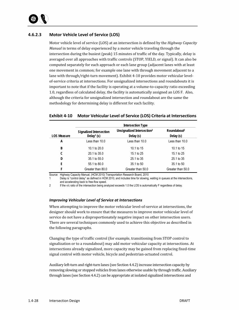
Motorvehiclelevelofservice(LOS)atanintersectionisdefinedbytheHighwayCapacityManualintermsofdelayexperiencedbyamotorvehicletravelingthroughtheintersectionduringthebusiest(peak)15minutesoftrafficoftheday.Typically,delayisaveragedoverallapproacheswithtrafficcontrols(STOP,YIELD,orsignal).Itcanalsobecomputedseparatelyforeachapproachoreachlanegroup(adjacentlaneswithatleastonemovementincommon;forexampleonelanewiththroughmovementadjacenttoalanewiththrough/right‐turnmovement).Exhibit4‐10providesmotorvehicularlevel‐of‐servicecriteriaatintersections.Forunsignalizedintersectionsandroundaboutsitisimportanttonotethatifthefacilityisoperatingatavolume‐to‐capacityratioexceeding1.0,regardlessofcalculateddelay,thefacilityisautomaticallyassignedanLOSF.Also,althoughthecriteriaforunsignalizedintersectionandroundaboutarethesamethemethodologyfordeterminingdelayisdifferentforeachfacility.
Exhibit 4‐10 Motor Vehicular Level of Service (LOS) Criteria at Intersections
Intersection Type
LOS Measure Signalized Intersection
Delay1 (s)
Unsignalized Intersection2
Delay (s)
Roundabout2
Delay (s)
A Less than 10.0 Less than 10.0 Less than 10.0
B 10.1 to 20.0 10.1 to 15 10.1 to 15
C 20.1 to 35.0 15.1 to 25 15.1 to 25
D 35.1 to 55.0 25.1 to 35 25.1 to 35
E 55.1 to 80.0 35.1 to 50 35.1 to 50
F Greater than 80.0 Greater than 50.0 Greater than 50.0
Source: Highway Capacity Manual, (HCM 2010) Transportation Research Board, 2010 1 Delay is “control delay” as defined in HCM 2010, and includes time for slowing, waiting in queues at the intersections,
and accelerating back to free-flow speed. 2 If the v/c ratio of the intersection being analyzed exceeds 1.0 the LOS is automatically F regardless of delay.
Improving Vehicular Level of Service at Intersections
Whenattemptingtoimprovethemotorvehicularlevel‐of‐serviceatintersections,thedesignershouldworktoensurethatthemeasurestoimprovemotorvehicularlevelofservicedonothaveadisproportionatelynegativeimpactonotherintersectionusers.Thereareseveraltechniquescommonlyusedtoachievethisobjectiveasdescribedinthefollowingparagraphs.Changingthetypeoftrafficcontrol(forexample,transitioningfromSTOPcontroltosignalizationortoaroundabout)mayaddmotorvehicularcapacityatintersections.Atintersectionsalreadysignalized,morecapacitymaybegainedfromreplacingfixed‐timesignalcontrolwithmotorvehicle,bicycleandpedestrian‐actuatedcontrol.Auxiliaryleft‐turnandright‐turnlanes(seeSection4.4.2)increaseintersectioncapacitybyremovingslowingorstoppedvehiclesfromlanesotherwiseusablebythroughtraffic.Auxiliarythroughlanes(seeSection4.4.2)canbeappropriateatisolatedsignalizedintersectionsand
Section 1 – Chapter 4
Intersection Design 1.4‐29
increaseintersectioncapacity.However,thelengthoftheauxiliarylanesforthereceivinglegwilldeterminetheabilityofthisextrathroughtraffictomerge.Ifauxiliarylanesaretooshort,theymaycongesttheintersectionandblocktheminorstreettraffic,andfailtoreducedelay.Thedesignershouldalsonotethataddingauxiliarylanesincreasesthecrossingdistanceforpedestrians.ThedesignershouldensurethatthelevelofserviceincreasesprovidedformotorvehiclesdonotresultinlargedegradationsinLOSforotherusers.Wherewideningtoprovideauxiliarylanesisplanned,thedesignershouldconsidercrossingislandsandotherfeaturestoensuretheabilityforpedestrianstocross.Atroundabouts,capacitycanbeincreasedbyanadditionalapproachlaneandacorrespondingsectionofadditionalcirculatinglane.Addingparallellinksofstreetnetworkmayreducetrafficvolumesatanintersection,therebyeliminatingorpostponingtheneedtoincreaseitscapacity.
4.6.2.4 Multimodal Level of Service
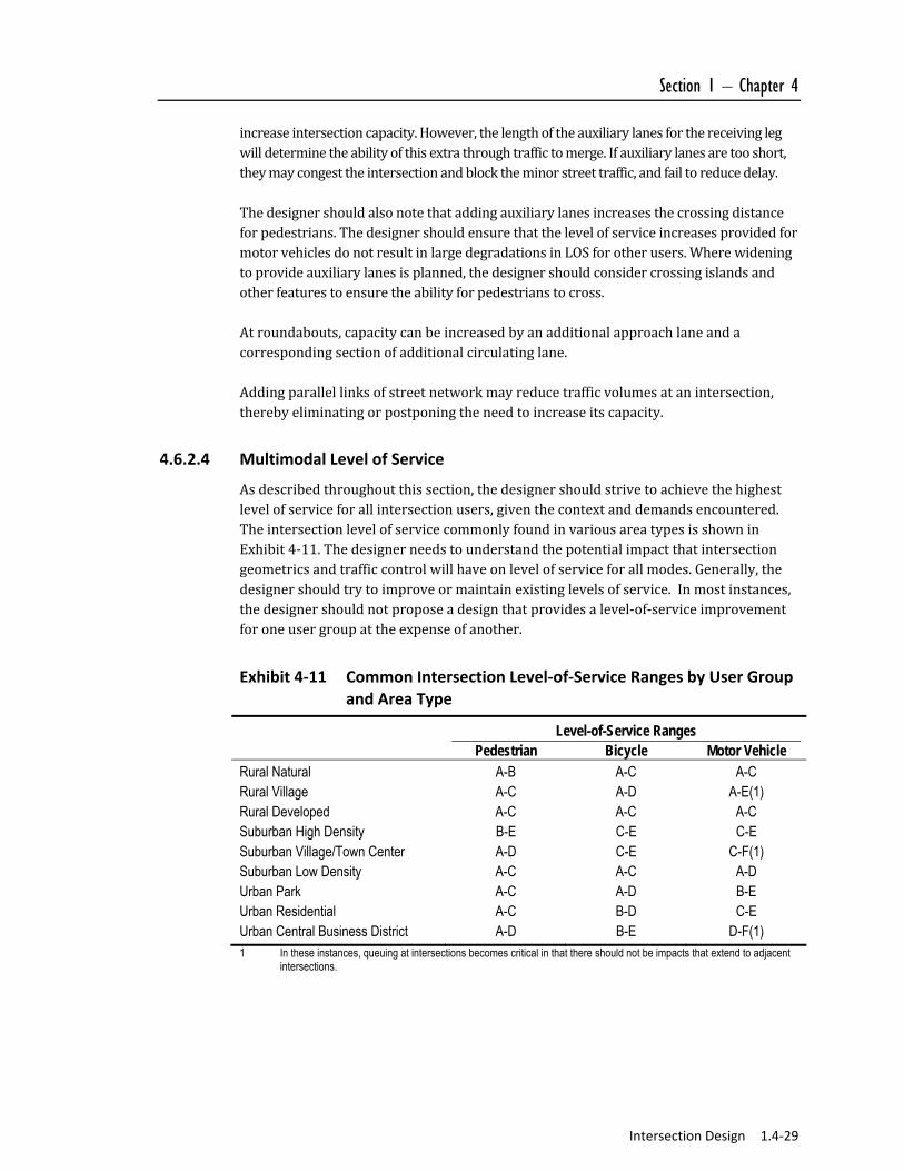
Asdescribedthroughoutthissection,thedesignershouldstrivetoachievethehighestlevelofserviceforallintersectionusers,giventhecontextanddemandsencountered.TheintersectionlevelofservicecommonlyfoundinvariousareatypesisshowninExhibit4‐11.Thedesignerneedstounderstandthepotentialimpactthatintersectiongeometricsandtrafficcontrolwillhaveonlevelofserviceforallmodes.Generally,thedesignershouldtrytoimproveormaintainexistinglevelsofservice.Inmostinstances,thedesignershouldnotproposeadesignthatprovidesalevel‐of‐serviceimprovementforoneusergroupattheexpenseofanother.
Exhibit 4‐11 Common Intersection Level‐of‐Service Ranges by User Group and Area Type
Level-of-Service Ranges Pedestrian Bicycle Motor Vehicle
Rural Natural A-B A-C A-C Rural Village A-C A-D A-E(1) Rural Developed A-C A-C A-C Suburban High Density B-E C-E C-E Suburban Village/Town Center A-D C-E C-F(1) Suburban Low Density A-C A-C A-D Urban Park A-C A-D B-E Urban Residential A-C B-D C-E Urban Central Business District A-D B-E D-F(1) 1 In these instances, queuing at intersections becomes critical in that there should not be impacts that extend to adjacent
intersections.
1.4‐30 Intersection Design DRAFT
4.7 Geometric Design Elements
Thefollowingsectionsdescribemanyofthedetaileddesignelementsassociatedwithintersectionsincludingintersectionalignment,pavementcornerradii,auxiliarylanes,channelizationislands,roundabouts,medianopenings,pedestriancurbcutrampsandcrosswalks,bicyclelanetreatments,andbusstops.
4.7.1 Intersection Alignment
Intersectionalignmentguidelinescontrolthecenterlinesandgradesofboththemajorandminorstreets,inturnestablishingthelocationofallotherintersectionelements(forexample,edgeofpavement,pavementelevation,andcurbelevation).
4.7.1.1 Horizontal Alignment
Ideally,streetsshouldintersectasclosetorightanglesaspractical.Skewedintersectionscanreducevisibilityofapproachingmotorvehiclesandbicycles,requirehigherdegreesoftrafficcontrol,requiremorepavementtofacilitateturningvehicles,andrequiregreatercrossingdistancesforpedestrians.GuidelinesforthemaximumcurvatureatintersectionsaregiveninExhibit4‐12.Curvaturethroughanintersectionaffectsthesightdistanceforapproachingmotorists,andmayrequireadditionaltrafficcontroldevices(warningsigns,stopsigns,signals,pavementmarkingsorroundabouts).Onhigher‐speedroads,superelevationoncurvesmayinclinethecrossslopeoftheintersectioninamanneruncomfortabletomotorists,orinconflictwithintersectionverticalalignmentguidelinesdescribedbelow.Theminimumtangentatcross‐streetapproach(TA)showninExhibit4‐12helpstoassurenecessarysightdistanceattheintersection,andtosimplifythetaskofdrivingformotoristsapproachingtheintersection.Often,insteepterrain,apermissiblegradecannotbeachievedwiththehorizontalalignmentguidelines.Typically,thisdesignchallengeisresolvedbyadheringtoverticalalignmentcriteria,whileincorporatingthenecessaryflexibilityinthehorizontalguidelines.

Section 1 – Chapter 4
Intersection Design 1.4‐31
Exhibit 4‐12 Horizontal Alignment Guidelines at Intersections
Design Speed (MPH)
Minimum Angle of Intersection (AI, degrees) Minimum Curve
Radius, Main Street (RM, feet)
Minimum Tangent Cross
Street Approach (TA, feet)
Arterial Major Street
Collector Major Street
Local Major Street
15 60 60 60 45 30 20 60 60 60 85 30 25 60 60 60 155 30 30 60 60 60 250 30 35 60 60 60 365 45 40 60 60 60 500 45 45 65 60 60 660 45 50 65 65 60 835 60 55 65 65 65 1065 60 60 70 65 65 1340 60
Source: MassDOT
4.7.1.2 Vertical Alignment
Themajorstreetandminorstreetprofileinfluencetheverticalalignmentofanintersection.
Major Street Profile
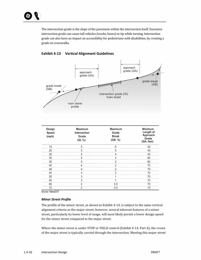
Theintersectionapproachgradeintheuphilldirection,asshowninExhibit4‐13,affectstheaccelerationofmotorvehiclesandbicyclesfromastoppedcondition,andthereforecanhaveanimpactonvehiculardelayattheintersection.Theintersectionapproachgradeinthedownhilldirectionaffectsthestoppingdistanceofapproachingmotorvehiclesandbicycles.
1.4‐32 Intersection Design DRAFT
Theintersectiongradeistheslopeofthepavementwithintheintersectionitself.Excessiveintersectiongradecancausetallvehicles(trucks,buses)totipwhileturning.Intersectiongradecanalsohaveanimpactonaccessibilityforpedestrianswithdisabilities,bycreatingagradeoncrosswalks.
Exhibit 4‐13 Vertical Alignment Guidelines
Source: MassDOT
Minor Street Profile
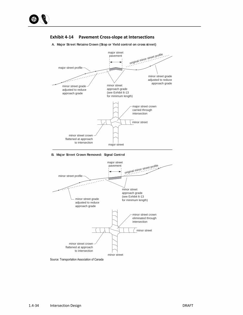
Theprofileoftheminorstreet,asshowninExhibit4‐14,issubjecttothesameverticalalignmentcriteriaasthemajorstreet;however,severalinherentfeaturesofaminorstreet,particularlyitslowerlevelofusage,willmostlikelypermitalowerdesignspeedfortheminorstreetcomparedtothemajorstreet.WheretheminorstreetisunderSTOPorYIELDcontrol(Exhibit4‐14,PartA),thecrownofthemajorstreetistypicallycarriedthroughtheintersection.Meetingthismajorstreet

Section 1 – Chapter 4
Intersection Design 1.4‐33
cross‐sectioncanresultinminorstreetgradesneartheintersectionthataresteeperthanthatwhichwouldoccurwiththemajorstreetcrownremoved.Atintersectionswherethemajorstreetretainsthecrownthroughtheintersection,theminorstreetcrownisgraduallyreduced,typicallystartingatthebeginningoftheapproachgrade,andcompletedslightlyoutsidetheintersection.Atintersectionswithsignalcontrol,itiscustomarytoremovethecrownfromboththemajorstreetandtheminorstreet.Thisremovalofthecrownisadvisableforthecomfortandsafetyofmotorvehicledriversandbicyclistsproceeding,oneitherstreet,atthedesignspeedthroughagreensignalindication.Atintersectionswithall‐waySTOPcontrol,itmaybedesirabletoremovethecrownfrombothintersectingstreets,toemphasizethatallapproachesareequalintermsoftheirtrafficcontrol.Eliminatingthecrownonthemajorstreetcan,undermanycircumstances,reducetheamountofmodificationthatmustbedonetotheminorstreetprofile(Exhibit4‐14PartB).Themajorstreetcrossslopecanbeinclinedinthesamedirectionattheminorstreetprofile,therebypermittingapproachgradesontheminorstreettobeaccommodatedwithminimalalterationtotheoriginalminorstreetprofile.Wherebothmajorstreetandminorstreetcrownsareeliminated,theirremovalisaccomplishedgradually,typicallyoverthelengthoftheapproachgrade.Whethercrownedornot,pavementgradeswithintheintersectionshouldnotexceedthevaluesgiveninExhibit4‐13.Inadditiontomeetingtheverticalprofileguidelinesasstatedabove,intersectionapproachesonbothmainandminorstreetsaresubjecttotheintersectionsighttrianglerequirements(seeChapter2).Undersomecircumstances,thesesighttrianglerequirementsmaydictateapproachgradesorlengthofapproachgradesdifferingfromthoseindicatedintheverticalalignmentguidelinesabove.
1.4‐34 Intersection Design DRAFT
Exhibit 4‐14 Pavement Cross‐slope at Intersections
Source: Transportation Association of Canada
A. Major Street Retains Crown (Stop or Yield control on cross street)
B. Major Street Crown Removed: Signal Control
major street profile
minor street gradeadjusted to reduceapproach grade
minor street crownflattened at approach
to intersection
minor street gradeadjusted to reduce
approach grade
major street crowncarried throughintersection
major streetpavement
major streetpavement
minor streetapproach grade(see Exhibit 6-13for minimum length)
original minor street profile
minor street profile
minor street gradeadjusted to reduceapproach grade
minor streetapproach grade(see Exhibit 6-13for minimum length)
original minor street profile
minor street
major street
minor street crownflattened at approach
to intersection
minor street crowneliminated throughintersection
minor street
minor street
Section 1 – Chapter 4
Intersection Design 1.4‐35
4.7.2 Pavement Corner Radius
Thepavementcornerradius—thecurveconnectingtheedgesofpavementoftheintersectingstreets—isdefinedbyeitherthecurbor,wherethereisnocurb,bytheedgeofpavement.Thepavementcornerradiusisakeyfactorinthemultimodalperformanceoftheintersection.Thepavementcornerradiusaffectsthepedestriancrossingdistance,thespeedandtravelpathofturningvehicles,andtheappearanceoftheintersection.Excessivelylargepavementcornerradiiresultinsignificantdrawbacksintheoperationofthestreetsincepedestriancrossingdistanceincreaseswithpavementcornerradius.Further,thespeedofturningmotorvehiclesmakingrightturnsishigheratcornerswithlargerpavementcornerradii.Thecompoundedimpactofthesetwomeasures—longerexposureofpedestrianstohigher‐speedturningvehicles—yieldsasignificantdeteriorationinsafetyandqualityofservicetobothpedestriansandbicyclists.Theunderlyingdesigncontrolinestablishingpavementcornerradiiistheneedtohavethedesignvehicleturnwithinthepermitteddegreesofencroachmentintoadjacentoropposinglanes.Exhibit4‐15illustratesdegreesofencroachmentoftenconsideredacceptablebasedontheintersectingroadwaytypes.Thesedegreesofencroachmentvarysignificantlyaccordingtoroadwaytype,andbalancetheoperationalimpactstoturningvehiclesagainstthesafetyofallotherusersofthestreet.AlthoughtheExhibitprovidesastartingpointforplanninganddesign,thedesignermustconfirmtheacceptabledegreeofencroachmentusingvehicleturningtemplatespresentedearlierinthischapterandinAASHTO’sAPolicyontheGeometricDesignofHighwaysandStreets.ForStateroadways,cornerradiishouldbeconsistentwiththeConnecticutDepartmentofTransportation’sHighwayDesignManual.Atthegreatmajorityofallintersections,whethercurbedorotherwise,thepavementcornerdesignisdictatedbytheright‐turnmovement.Leftturnsareseldomacriticalfactorincornerdesign,exceptatintersectionsofone‐waystreets,inwhichcasetheircornerdesignissimilartothatforrightturnsatintersectionsoftwo‐waystreets.ThemethodforpavementcornerdesigncanvaryasillustratedinExhibit4‐16anddescribedbelow.
Simplecurbradius:Atthevastmajorityofsettings,asimpleradius(curborpavementedge)isthepreferreddesignforthepavementcorner.Thesimpleradiuscontrolsmotorvehiclespeeds,usuallyminimizescrosswalkdistance,generallymatchestheexistingnearbyintersectiondesignsandiseasilydesignedandconstructed.
Compoundcurvesortaper/curvecombinations:Whereencroachmentbylargermotorvehiclesmustbeavoided,whereturningspeedshigherthanminimumaredesirable,orwhereangleofturnisgreaterthan90degrees,compoundcurvescandefineacurb/pavementedgecloselyfittedtotheouter(rear‐wheel)vehicletrack.Combinationsoftaperswithasinglecurveareasimple,andgenerallyacceptable,approximationtocompoundcurves.

1.4‐36 Intersection Design DRAFT
Turningroadways:Aseparateright‐turnroadway,usuallydelineatedbychannelizationislandsandauxiliarylanes,maybeappropriatewhereright‐turnvolumesarelarge,whereencroachmentbyanymotorvehicletypeisunacceptable,wherehigherspeedturnsaredesired,orwhereangleofturniswellabove90degrees.
4.7.2.1 Simple Curb Radius
Pavementcornerdesignatsimpleintersectionsiscontrolledbythefollowingfactors:
Theturningpathofthedesignmotorvehicle.DesignmotorvehiclesappropriateforthevariousroadwaytypesaresummarizedinSection4.3.3ofthischapter.
Theextent(ifany)ofencroachment,intoadjacentoropposingtrafficlanes,permittedbythedesignmotorvehicledeterminedfromExhibit4‐15.
The“effective”pavementwidthonapproachanddeparturelegsisshowninExhibit4‐17.Thisisthepavementwidthusable,bythedesignmotorvehicle,underthepermitteddegreeofencroachment.Ataminimum,effectivepavementwidthisalwaystheright‐handlaneandthereforeusuallyatleast11‐12feet,onboththeapproachanddeparturelegs.Whereon‐streetparkingispresent,theparkinglane(typically7‐8feet)isaddedtotheeffectivewidthonthoselegs(approach,departureorboth)withon‐streetparking.Typically,legswithon‐streetparkinghaveaneffectivepavementwidthofaround20feet.Theeffectivewidthmayincludeencroachmentintoadjacentoroppositelanesoftraffic,wherepermitted.Amaximumof10feetofeffectivewidth(i.e.,asinglelaneoftraffic)maybeassumedforsuchencroachment.

Section 1 – Chapter 4
Intersection Design 1.4‐37
Exhibit 4‐15 Typical Encroachment by Design Vehicle
To (Departure Street)
For Tractor/Trailer (WB 50) For Single-Unit Truck (SU) For Passenger Car (P)
F
rom
(App
roac
h St
reet
)
Arterial Collector Local Arterial Collector Local Arterial Collector Local
Arterial (Art)
A B C A B C A A A
Collector (Col)
B B C B B C A A A
Local (Loc)
B D D C C D A B B
A, B, C, D defined in above diagrams. Note: Cases C and D are generally not desirable at signal controlled intersections because traffic on stopped street has
nowhere to go. Source: Adapted from ITE Arterial Street Design Guidelines.

1.4‐38 Intersection Design DRAFT
Exhibit 4‐16 Methods for Pavement Corner Design
Source: Adapted from A Policy on the Geometric Design of Streets and Highways, AASHTO, 2011. Chapter 9 Intersections
Exhibit 4‐17 Effective Pavement Widths
Note: The letters A, B, C, and D refer to the typical encroachment conditions illustrated in Exhibit 4-15. Source: MassDOT

Section 1 – Chapter 4
Intersection Design 1.4‐39
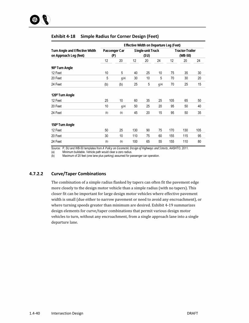
Exhibit4‐18summarizesthesimplecurbradiusneededforvariousdesignmotorvehicles,reflectingtheextentofencroachmentandeffectivepavementwidth.Generalguidelinescanbeconcludedforright‐angle(90degree)intersections:
A15‐footsimplecurbradiusisappropriateforalmostallright‐angle(90degree)turnsonlocalstreets.Thisradiuspermitspassengercarstoturnwithnoencroachmentandaccommodatesthesingleunit(SU)truckwithacceptabledegreesofencroachment.Theoccasionaltractor/trailertruck(WB‐50)canalsonegotiatethe15‐footcornerradiuswithinitsacceptabledegreeofencroachment.
Wherethemajorstreetisacollectorstreet,a20‐30footradiusislikelytobeadequate.Whereparkingispresent,yieldinganeffectivewidthof20feet,thetypicaldesignmotorvehiclefortheintersection(theSUtruck)canturnwithlessthana20footcornerradius,withoutencroachment.Onsinglelaneapproachesanddepartures,withnoon‐streetparking,theSUvehiclecanbeaccommodatedwitha25‐footradiusandan8‐footencroachment(i.e.,a20footeffectivewidth)onthedeparture.Atlocationswherenoencroachmentcanbetolerated,aradiusof40feetwillpermittheSUtrucktoapproachanddepartwithinasinglelane.
ForarterialstreetswheretheWB‐50truckisthedesignvehicle,a35‐footradiusisadequateundermostcircumstancesofapproachanddepartureconditions.However,withasingleapproachanddeparturelane,andwithnoencroachmenttolerated,aradiusashighas75feetisrequired.Inthissituation,aturningroadwaywithchannelizationislandmaybeapreferablesolution.
OnStateroadways,cornerradiidesignshouldbeconsistentwiththeCTDepartmentofTransportation’sHighwayDesignManual.Atskewedintersections(turnanglegreaterthan90degrees),thesimpleradiusrequiredfortheSUandWB‐50vehicleissignificantlylargerthanthatneededfor90degreeintersections.Curve/tapercombinationsorturningroadwaysmaybeappropriateinthesesituations.
1.4‐40 Intersection Design DRAFT
Exhibit 4‐18 Simple Radius for Corner Design (Feet)
Turn Angle and Effective Width on Approach Leg (feet)
Effective Width on Departure Leg (Feet)
Passenger Car (P)
Single-unit Truck (SU)
Tractor-Trailer (WB-50)
12 20 12 20 24 12 20 24
90O Turn Angle 12 Feet 10 5 40 25 10 75 35 30 20 Feet 5 5(a) 30 10 5 70 30 20
24 Feet (b) (b) 25 5 5(a) 70 25 15
120O Turn Angle
12 Feet 25 10 60 35 25 105 65 50
20 Feet 10 5(a) 50 25 20 95 50 40
24 Feet (b) (b) 45 20 15 95 50 35
150O Turn Angle
12 Feet 50 25 130 90 75 170 130 105
20 Feet 30 10 110 75 60 155 115 95
24 Feet (b) (b) 100 65 55 155 110 80
Source: P, SU and WB-50 templates from A Policy on Geometric Design of Highways and Streets, AASHTO, 2011. (a) Minimum buildable. Vehicle path would clear a zero radius. (b) Maximum of 20 feet (one lane plus parking) assumed for passenger car operation.
4.7.2.2 Curve/Taper Combinations
Thecombinationofasimpleradiusflankedbytaperscanoftenfitthepavementedgemorecloselytothedesignmotorvehiclethanasimpleradius(withnotapers).Thiscloserfitcanbeimportantforlargedesignmotorvehicleswhereeffectivepavementwidthissmall(dueeithertonarrowpavementorneedtoavoidanyencroachment),orwhereturningspeedsgreaterthanminimumaredesired.Exhibit4‐19summarizesdesignelementsforcurve/tapercombinationsthatpermitvariousdesignmotorvehiclestoturn,withoutanyencroachment,fromasingleapproachlaneintoasingledeparturelane.

Section 1 – Chapter 4
Intersection Design 1.4‐41
Exhibit 4‐19 Curve and Taper Corner Design
Source: Adapted from A Policy on the Geometric Design of Streets and Highways, AASHTO, 2011. Chapter 9 Intersections
Exhibit 6‐4‐20 Turning Roadways and Islands
Turning Roadway, Edge of Pavement Angle of Turn
(Degrees) Design Vehicle
Radius (feet) R1-R2-R1
Offset (OS feet)
75 P 100-75-100 2.0 SU 120-45-120 2.0 WB -50 150-50-150 6.5
90 P 100-20-100 2.5 SU 120-40-120 2.0 WB -50 180-60-180 6.5
105 P 100-20-100 2.5 SU 100-35-100 3.0 WB -50 180-45-180 8.0
120 P 100-20-100 2.0 SU 100-30-100 3.0 WB -50 180-40-180 8.5
150 P 75-20-75 2.0 SU 100-30-100 4.0 WB -50 160-35-160 7.0
Note: W (width) should be determined using the turning path of the design vehicle. Source: Adapted from A Policy on the Geometric Design of Streets and Highways, AASHTO, 2011. Chapter 9 Intersections

1.4‐42 Intersection Design DRAFT
4.7.3 Auxiliary Lanes
Thedesignelementsofthreeauxiliarylanestypesaredescribedinthefollowingsections:left‐turnlanes,right‐turnlanes,andthroughlanes.Decelerationandtaperdistancesprovidedbelowshouldbeacceptedasadesirablegoalandshouldbeprovidedforwherepractical.However,inurbanareasitissometimesnotpracticaltoprovidethefulllengthofanauxiliarylane.Insuchcases,atleastpartofthedecelerationmustbeaccomplishedbeforeenteringtheauxiliarylane.Chapter9ofAASHTO’sGeometricDesignofHighwaysandStreetsprovidesmoreinformationforthedesigner.ThedesignofauxiliarylanesonaStateroadwaysshouldbeconsistentwiththeCTDepartmentofTransportation’sHighwayDesignManual.
4.7.3.1 Left‐Turn Lane Design Elements
Left‐turnlanesremovestoppedorslow‐movingleft‐turningmotorvehiclesfromthestreamofthroughtraffic,eliminatingtheprimarycauseofrear‐endcrashesatintersections.Thesafetybenefitsofleft‐turnlanesincreasewiththedesignspeedoftheroad,astheygreatlyreduceboththeincidenceandseverityofrear‐endcollisions.Left‐turnlanesalsoimprovecapacitybyfreeingthetravellanesforthroughtrafficonly.Thesafetyandcapacitybenefitsofleft‐turnlanesapplytoallvehiculartraffic,motorizedaswellasnon‐motorized.However,left‐turnlanesaddtothepedestriancrossingdistanceandpedestriancrossingtime.Theadditionalstreetwidthneededforleft‐turnlanesmayrequirelandtakingorremovalofon‐streetparking.Thelengthsofleft‐turnlanes,illustratedinExhibit4‐21,dependonthevolumeofleft‐turningmotorvehiclesandthedesignspeed.Thelengthoftaperrequiredtoformtheleft‐turnlanevarieswithdesignspeed.Atsignalizedintersections,aconservativeguidelinefordeterminingthestoragelengthofaleft‐turnlaneis150percent(1.5times)ofthelengthoftheaveragenumberofleft‐turningvehiclesarrivingduringasinglesignalcycleinthepeakhour.Amoreanalyticalguidelineforthelengthofrequiredstoragelaneistoobtaintheexpectedlengthoftheleft‐turnqueueandassociatedprobabilitiesfromintersectionanalysiscomputations(computerizedversionsofHighwayCapacityManualmethodologyorderivativeprogramssuchasSYNCHRO).Typically,left‐turnlanesaresizedtoaccommodatethemaximumlengthofqueueforthe95thpercentiletrafficvolumes,aqueuelengththatisexceededononly5percentofthepeak‐hourtrafficsignalcycles.

Section 1 – Chapter 4
Intersection Design 1.4‐43
Exhibit 4‐21 Left‐Turn Lane Design Guidelines
Dimensions for Left-Turn Lane Elements (feet)
Design Speed (mph)
Lane Width
(W, feet)
Deceleration Distance
(feet)1
Storage Distance2
(feet)
Length of Lane2
(L, feet)
Taper Length
(T, feet)3
Widened Taper Length (T, feet)
15-25 10 115 50 165 100 See Note 4 30-35 10 170 50 220 100 See Note 4 40 10-11 275 75 350 110 See Note 4 45 10-11 340 75 415 150 See Note 4 50 11-12 410 75 485 180 See Note 4 55 11-12 485 75 560 180 See Note 4 60 12 530 75 605 180 See Note 4
Source: Adapted from A Policy on the Geometric Design of Streets and Highways, AASHTO, 2011. Chapter 9 Intersections 1 For deceleration grades of 3 percent or less. 2 Storage distance and therefore total lane length (L) are based on an unsignalized left-turn volume of 100 vehicles hourly.
For larger volumes, compute storage need by formula or from intersection analysis queue calculation. 3 This taper length is not applicable for “widened for turn lane” cases, see note 4. 4 For “widened for turn lane” cases, use T = WS2/60 for speeds less than 45 mph and T = WS for speeds 45 mph and greater.

1.4‐44 Intersection Design DRAFT
4.7.3.2 Right‐Turn Lane Design Elements
Rightturnlanesareusedtoremovedeceleratingright‐turningmotorvehiclesfromthetrafficstream,andalsotoprovideanadditionallaneforthestorageofright‐turningmotorvehicles.Wheretheright‐turnvolumeisheavy,thisremovaloftheturningmotorvehiclefromthetrafficstreamcanalsoremoveaprimarycauseofrear‐endcrashesatintersections.Designelementsforright‐turnlanesaresummarizedinExhibit4‐22.
Exhibit 4‐22 Right‐Turn Lane Design Guidelines
Dimensions for Right-Turn Lane Elements (feet)
Design Speed1 (mph)
Lane Width
(W. feet)
Turning Lane Width (WT, feet)
Deceleration Distance
(feet)
Storage Distance2
(feet)
Length of Lane2
(L, feet)
Taper Length (T, feet)
15-25 10 14 115 50 165 100
30-35 10 14 170 50 220 100
40 10-11 15 275 60 335 110
45 10-11 15 340 60 400 150
50 11-12 15 410 60 470 180
55 11-12 16 485 60 545 180
60 12 16 530 60 590 180 Source: Adapted from A Policy on the Geometric Design of Streets and Highways, AASHTO, 2004. Chapter 9 Intersections 1 Based on grades of less than three percent for speeds less than 60 mph. Based on grades of less than two percent for
speeds greater than 60mph. 2 Storage distance and therefore total lane length (L) are based on an unsignalized right-turn volume of 100 vehicles
hourly. For larger volumes, compute storage need by formula or from intersection analysis queue calculation.
Right‐turnlanesprovideasafetyandcapacitybenefitformotorizedtraffic.However,inareasofhighpedestrianorbicyclistactivity,thesebenefitsmaybeoffsetbytheadditionalpavementwidthintheintersection,higherspeedsofmotorvehicularturningmovements,

Section 1 – Chapter 4
Intersection Design 1.4‐45
andvehicle/bicyclistconflictcreatedasmotoristsenteraright‐turnlaneacrossanon‐streetbicyclelaneoracrossthepathofbicycletrafficoperatingnearthecurb.
4.7.3.3 General Criteria for Right‐Turn and Left‐Turn Lanes
Criteriaforconsideringinstallationofleft‐turnlanesaresummarizedinExhibit4‐23.Thesecriteriaarebasedonacombinationofleft‐turningmotorvehiclevolumesplusopposingthroughmotorvehiclevolumesatunsignalizedlocations.Forexample,if330vehiclesperhourtraveleastboundat40mphandfivepercentareturningleft,anexclusiveleft‐turnlaneiswarrantedoncethewestboundvolumeexceeds800vehiclesperhour.
Exhibit 4‐23 Criteria for Left Turn Lanes
A. Unsignalized Intersections, Two-Lane Roads and Streets1:
Design Speed
Opposing Volume (motor vehicles
per hour)
Advancing Motor Vehicle Volume (vehicles per hour) 5%
Left Turns 10%
Left Turns 20%
Left Turns 30%
Left Turns 30 mph or less 800 370 265 195 185 600 460 345 250 225 400 570 430 305 275 200 720 530 390 335 40 mph 800 330 240 180 160 600 410 305 225 200 400 510 380 275 245 200 640 470 350 305 50 mph 800 280 210 165 135 600 350 260 195 170 400 430 320 240 210 200 550 400 300 270 60 mph 800 230 170 125 115 600 290 210 160 140 400 365 270 200 175 200 450 330 250 215
B. Signalized Intersections2: Left-Turn Lane Configuration Minimum Turn Volume
Single exclusive left-turn lane 100 motor vehicles per hour Dual exclusive left-turn lane 300 motor vehicles per hour
1 AASHTO Green Book (1990) 2 Source: Highway Capacity Manaual (2000)
Considerableflexibilityshouldbeexercisedinconsideringleft‐turnlanes.Typically,theyinvolvelittleimpacttothesetting,whilegenerallyyieldinglargebenefitsinsafetyanduserconvenience.Left‐turnlanesmaybedesirableinmanysituationswithvolumeswellbelowthosestated.Theseincludetodestinationsofspecialinterest(shopping,majorinstitutions,etc.),orforlocationswithmarginalsightdistanceonthemainroadoraconsistentoccurrenceofrear‐endcrashes.

1.4‐46 Intersection Design DRAFT
Wherethereisaneedformultiple,closelyspacedleft‐turnlanes(duetodrivewaysorsmallblocks),itmaybeadvisabletodesignateacontinuouscenterlaneasa“two‐wayleftturnlane”(TWLTL)asdiscussedinChapters3and7.Criteriafortheinstallationofright‐turnauxiliarylanesaremorejudgmentalthanthenumericalguidelinesfortheirleft‐turnlanecounterpart.Positiveandnegativeindicators(i.e.,conditionsfavoringorarguingagainstright‐turnlanes)aresummarizedinExhibit4‐24.
Exhibit 4‐24 Criteria for Right‐Turn Lane Placement
Positive Criteria (Favoring Right-Turn Placement)
Negative Indicators (Arguing Against Right-Turn Lane Placement)
High speed arterial highways In residential areas
High right-turn motor vehicle volumes In urban core areas
High right-turn plus high cross-street left-turn volumes On walking routes to schools
Long right-turn queues Where pedestrians are frequent
Intersection capacity nearly exhausted Low right turn volumes
History of crashes involving right-turning vehicles
Little to no pedestrian activity
Source: Adapted from A Policy on the Geometric Design of Streets and Highways, AASHTO, 2011. Chapter 9 Intersections
4.7.3.4 Auxiliary Through Lane Design Elements
Shortsegmentsofadditionalthroughlane(wideningastreetthroughasignalizedintersection)canbeaneffectivewayofincreasingintersectioncapacityatrelatively“isolated”intersections(forexample,inruralareasandinsettledareaswithaminimumofaboutone‐milespacingbetweensignalizedintersections).Wherethroughlanesareprovided,motoristsapproachingtheintersectionarrangethemselvesintotwolanesoftrafficandmergebacktoasinglelaneoftrafficonthedeparturesideoftheintersection.Mergingunderacceleration(i.e.,onthedeparturesideoftheintersection)workswell,sincegaps(spacesbetweenmotorvehicles)areincreasingasvehiclesaccelerate,leavingnumerousopportunitiestomergeasthetrafficstreamleavestheintersection.DesignelementsforauxiliarythroughlanesaregiveninExhibit4‐25.

Section 1 – Chapter 4
Intersection Design 1.4‐47
Exhibit 4‐25 Auxiliary Through Lane Design Guidelines
Dimensions for Auxiliary Through-Lanes (feet)
Design Speed (mph)
Lane Width (feet)
Taper Length
(T, feet)1
Length of Lane
(L, feet)
15-25 10 WS2/60 See Note 2
30-35 10 WS2/60 See Note 2
40 10-11 WS2/60 See Note 2
45 10-11 WS See Note 2
50 11-12 WS See Note 2
55 11-12 WS See Note 2
60 12 WS See Note 2 1 W is the lateral shift required to form the additional through lane. 2 L should be based on anticipated queue derived from intersection operations analysis. Source: Adapted from A Policy on the Geometric Design of Streets and Highways, AASHTO, 2011. Chapter 9 Intersections and
the Manual on Uniform Traffic Control Devices
4.7.4 Channelization Islands
Channelizationislandsareusedto:
Delineatetheareainwhichmotorvehiclescanoperate; Reducetheareaofmotorvehicleconflict; Bringmotorvehiclemergingintoasafer(smaller)angleofmerge;and Providepedestrianrefuge.
Ideally,channelizationislandsareraisedabovepavementlevel,typicallytocurbheight(6inches).Lesspreferably,theymaybeflushwiththepavementlevel.Bothraisedandflushislandsmaybeconstructedofavarietyofmaterials,includingconventionallyfinishedconcrete,scoredconcrete,orrigidpaversofvarioustypes.Somegeneralcriteriaforthedimensionsofchannelizationislandsinclude:

1.4‐48 Intersection Design DRAFT
Triangularislandsshouldbeaminimumof100squarefeetinsurfaceareawithonesideatleast15feetinlength.Linearislandsshouldbeatleast2,andpreferably3feetormorewide.Iftheycontainsigns,theyshouldbeatleast4feetwide.Iftheyintersectpedestriancrosswalksorcontainsigns,theyshouldbeatleast6feetwidewithmaximum1.5percentslope.Theminimumlengthoflinearislandsshouldbe25feet.
Channelizationislandsshouldcontainat‐gradepassagesforbicyclelanes,wheelchairandpedestrianpaths,andshouldgenerallybeplacedtoavoidimpedingbicyclemovement,whetherornotbicyclelanesarepresent.
Theedgesofchannelizationislandsshouldbeoffsetfromthetravellanes,toguidedriverssmoothlyintothedesiredpath.Typically,a2‐footoffsetisappropriate.
TypicalarrangementsandapplicationsofchannelizationareshowninExhibit4‐26.
4.7.4.1 Right‐turn Channelization Islands
Asmallchannelizationislandcandelineatearight‐turnlaneatasimpleintersection(i.e.,whereneithertheapproachnordeparturelaneisflared).Thistypeofchannelizationisappropriateforlarge‐radiuscorners.Amorecommonusefortheright‐turnchannelizationislandisatflaredintersections,whereadecelerationlaneflareisprovidedontheapproachtotheintersection,sometimescombinedwithanaccelerationlaneflareonthedepartureside.Thelargestchannelizationislandsaretypicallyfoundwhereanauxiliaryright‐turnlaneisprovidedonboththeapproachanddeparturesideoftheintersection.Right‐turnchannelizationislandscanbenefitpedestrianscrossingtheaffectedapproachesbyprovidinganinterimrefugeinthecrosswalk.Thisrefugepermitspedestrianstodevotefullattentiontocrossingtheright‐turnlanewithoutneedingtoassureasafecrossingfortherestofthestreet.Fromthechannelizationisland,pedestrianscanthenproceedacrossthethroughlanesoftrafficwithoutthecomplicatingfactorofcrossingtheright‐turnmovement.
4.7.4.2 Divisional Islands
Divisionalislandsareusefulindividingopposingdirectionsoftrafficflowatintersectionsoncurves,orwithskewedanglesofapproach.Insuchinstances,theycanimprovethesafetyandconvenienceforapproachingmotorists.Althoughsuperficiallysimilartomedians,divisionalislandsdifferfromthemintheirshortlengthandrelativelynarrowwidthandarediscussedfurtherlaterinthischapterandinChapter6.
4.7.4.3 Left‐Turn Lane Delineator Islands
Theleft‐turndelineatorislandresemblesashortsectionofmedianisland,withtriangularstripingtoguidetrafficaroundit.Attheintersectionendoftheisland,itisnarrowedtoprovidestorageforleft‐turningmotorvehiclesandbicycles.
Section 1 – Chapter 4
Intersection Design 1.4‐49
Onundividedstreets,theleft‐turnlanedelineatorislandisusedtoformtheleft‐turnbay.Atitsupstreamnose(i.e.,ontheapproachtotheintersection),theislandandassociatedstripingshiftsthethroughtrafficlanetotheright,creatingroomforthetaperandleft‐turnbay.

1.4‐50 Intersection Design DRAFT
Exhibit 4‐26 Channelization Islands
Source: Adapted from A Policy on the Geometric Design of Streets and Highways, AASHTO, 2011. Chapter 9 Intersections
Section 1 – Chapter 4
Intersection Design 1.4‐51
4.7.5 Roundabout Geometric Design Elements
ThekeyelementsofgeometricdesignforroundaboutsareshowninExhibit4‐27andinclude:
Thecirculatingroadway,whichcarriesmotorvehiclesandbicyclesaroundtheroundaboutinacounterclockwisedirection.
Thecentralisland,definingtheinnerradiusofthecirculatingroadwayaroundit.
Acoreareawithinthecentralisland,fromwhichmotorvehiclesareexcluded.
Atruckapronareaontheouterperimeterofthecentralisland,traversablebylargemotorvehicles.
Theinscribedcircle,definedbytheouteredgeofthecirculatingroadway.
Splitterislands,onallapproaches,separatingtheenteringfromtheexitingtraffic.
Crosswalksacrossapproachanddepartureroadways.
Thekeydesignelementoftheroundaboutisitsouterdiameter,theinscribedcirclediameter(ICD).Thisdimensiondeterminesthedesignofthecirculatingroadwayandcentralislandwithinit.Thealignmentofapproachanddepartureroadwaysandtheresultingsplitterislandsarealsoestablishedbytheinscribedcircle.ForfurtherinformationonroundaboutdesignrefertotheFHWApublicationRoundabouts:AnInformationalGuide,2010.
4.7.5.1 Inscribed Circle
TheICDisderivedfromthemotorvehicle.Theinscribedcircleisestablishedbytheouterturningradiusofthedesignvehicle,plusamarginforcontingenciesencounteredinnormaloperation.
4.7.5.2 Width of Circulating Roadway
Thewidthofthecirculatingroadwayisestablishedfromtheturningpathofthedesignvehicleplusamargintoallowfornormaloperatingcontingencies.Thecriticalturningmovementistheleftturn,requiringa270degreemovementaroundthecirclewhich,inturn,producesthelargestsweptmotorvehiclepathandtherebyestablishesthewidthofthecirculatingroadway.

1.4‐52 Intersection Design DRAFT
Exhibit 4‐27 Circle Dimensions, Single Lane Roundabout
Note: The design vehicle should be the largest vehicle expected to be accommodated on the street. Source Roundabouts: An Informational Guide, FHWA 2010.
4.7.5.3 Central Island
Thediameterofthecentralislandisderivedfromthediameteroftheinscribedcirclelessthewidthofthecirculatingroadway.Typically,centralislandsconsistofacoreareanotintendedtobetraversedbymotorvehiclesandbicycles,borderedbyatruckapronofaslightlyraisedpavementnotintendedtobeusedbyvehiclessmallerthanaschoolbus,butavailablefortheinnerrearwheeltrackoflargermotorvehicles.
4.7.5.4 Entry and Exit Curves
Theentryradiuscanbevariedasdesiredtoachievethedesiredentryspeed.Curvatureislimitedonlybytheneedtoprovidesufficientclearanceforthedesignvehicle.Entranceroadwaysaredesignedsothatthecontinuationoftheinsideedgeoftheentrycurvejoinstangentiallytothecentralisland,whiletheoutsideedgeoftheentrycurvejoinssmoothlyandtangentiallytotheoutsideedgeofthecirculatingroadway.Typically,theentryradii(measuredattheoutsidepavementedge)rangefrom30to100feet.Exitcurvesjointangentiallytotheinnerandouterdiametersoftheroundaboutinthesamemannerastheentrycurve.Theoutsideexitcurvejoinssmoothlyandtangentiallytotheoutsideedgeofthecirculatingroadway,whiletheinsidecurve,ifcontinued,wouldjointangentiallytothecentralisland.Aswiththeentrycurve,thewidthoftheroadwayshouldaccommodatethedesignmotorvehicle.Theexitpathradius(measured

Section 1 – Chapter 4
Intersection Design 1.4‐53
atthecenterlineoftheexitcurve)shouldbeatleastasgreatasthemotorvehiclepatharoundthecirculatingroadway,sothatdriversdonotreducespeeduponleavingthecircle,or,failingthat,overruntheexitcurveandcollidewiththesplitterisland.Frequently,exitcurveshavelargerradiithanentrycurves,toreducethepossibilityofcongestionattheexitpoints.However,theexitspeedshouldalsobeinfluencedbytheaccommodationofpedestriansandbicyclists.
4.7.5.5 Splitter Islands
SplitterislandsareformedbytheseparationbetweentheentryandexitlanesasillustratedinExhibit4‐28.Splitterislandsguidemotorvehiclesandbicyclesintotheroundabout,separatetheenteringandexitingtrafficstreams,assureamergebetweenenteringandcirculatingtrafficatanangleoflessthan90degrees,andassistincontrollingspeeds.Further,splitterislandsprovidearefugeforpedestriansandbicyclists,andcanbeusedasaplaceformountingsigns.Largersplitterislandsaffordtheopportunityforattractivelandscaping,butsignsandlandscapingmustnotobstructsightdistanceforapproachingmotorists.Splitterislandsshouldbeatleast50feetintotallengthtoproperlyalertdriverstotheroundabout.Thesplitterislandshouldextendbeyondtheendoftheexitcurvetoassurethatexitingtraffichascompleteditsturn,andtopreventitfromcrossingintothepathofon‐comingtraffic.
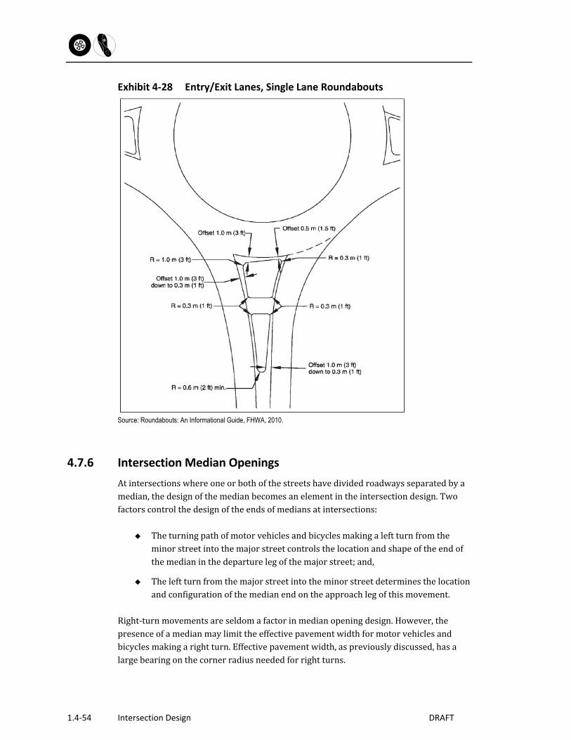
1.4‐54 Intersection Design DRAFT
Exhibit 4‐28 Entry/Exit Lanes, Single Lane Roundabouts
Source: Roundabouts: An Informational Guide, FHWA, 2010.
4.7.6 Intersection Median Openings
Atintersectionswhereoneorbothofthestreetshavedividedroadwaysseparatedbyamedian,thedesignofthemedianbecomesanelementintheintersectiondesign.Twofactorscontrolthedesignoftheendsofmediansatintersections:
Theturningpathofmotorvehiclesandbicyclesmakingaleftturnfromtheminorstreetintothemajorstreetcontrolsthelocationandshapeoftheendofthemedianinthedeparturelegofthemajorstreet;and,
Theleftturnfromthemajorstreetintotheminorstreetdeterminesthelocationandconfigurationofthemedianendontheapproachlegofthismovement.
Right‐turnmovementsareseldomafactorinmedianopeningdesign.However,thepresenceofamedianmaylimittheeffectivepavementwidthformotorvehiclesandbicyclesmakingarightturn.Effectivepavementwidth,aspreviouslydiscussed,hasalargebearingonthecornerradiusneededforrightturns.
Section 1 – Chapter 4
Intersection Design 1.4‐55
4.7.6.1 Design Vehicles for Median Openings
Thedesignvehicleformedianopeningsisthesameasthedesignvehicleselectedfortheintersection.Roadswithmediansarelikelytobeclassifiedasarterialroads,withtheappropriatedesignvehiclethereforebeingtheWB‐50truck.However,forsomemedianopenings,thepassengercar(P)orsingleunittruck(SU)designvehiclemaybeappropriate.
4.7.6.2 Permitted Encroachment at Median Openings
Atintersectionsofstreetswithmedians,turningvehiclesmaybepermittedtoencroachintoadjacentlanes,accordingtoguidelinesdiscussedearlier.However,ondividedhighways,encroachmentintoopposinglanesoftrafficisphysicallyimpossible,duetothemedian.Somecategoriesofencroachment,therefore,eventhoughpermissible,maynotbeavailablefortheturninquestion.
4.7.6.3 Median and Design Controls
Theleft‐turnmovementfromtheminorstreetintothedeparturelegofthemajorstreetcontrolstheplacementandshapeoftheaffectedmedianisland.Similarly,theleftturnfromthedividedmajorstreetintotheminorstreetcontrolstheplacementandshapeoftheaffectedmedianislandonthatapproachlegoftheintersection.Whereboththemajorstreetandtheminorstreetaredivided,thefourpossibleleftturnscontrolthelocationandshapesofallfourmedianislands.
4.7.6.4 Median Openings
Animportantdesignelementisthelengthofthemedianopening,assummarizedinExhibit4‐29.Openingdimensionsaregivenfortwoconfigurationsofmedianend:semi‐circularandbullet‐nose.Medianopeningsaregivenforthethreecategoriesofdesignvehicleaddressedthroughoutthischapter:passengercar(P),singleunittruck(SU),andthetractor/50‐foottrailer(WB‐50).

1.4‐56 Intersection Design DRAFT
Exhibit 4‐29 Median Openings
Note: R1, R2 and NL determined by design vehicle turning paths. Source: Adapted from A Policy on the Geometric Design of Streets and Highways, AASHTO, 2011. Chapter 9 Intersections

Section 1 – Chapter 4
Intersection Design 1.4‐57
4.7.7 Pedestrian Crosswalks
Crosswalksareacriticalelementofintersectiondesign.Crosswalksareessentialfordesignatingtheappropriatepathoftravelforapedestrianthroughtheintersection.Crosswalksaredefinedbypavementmarkings,texturedpavement,andcoloredpavementasdescribedbelow.Severaltechniquesareavailabletoshortenpedestriancrossingsandforimprovingcrosswalkvisibility,asdescribedbelow.
4.7.7.1 Crosswalk Pavement Markings
Pavementmarkingsindicatetopedestrianstheappropriaterouteacrosstrafficandremindturningmotorvehicledriversandbicyclistsofpotentialconflictswithpedestrians.Thecrosswalkedgenearesttotheintersectionshouldbealignedwiththeedgeofthesidewalknearesttotheroad.Whendifferentpavementtreatmentsareused,crosswalksmustbeboundedbyparallelbars.Atsignalizedintersections,allcrosswalksshouldbemarked.TobeconsistentwithConnDOTpolicy,crosswalksatsignalizedintersectionsshouldbe8‐feetwidewith16‐inchbarsandspaces(forstandardcrossings)or24‐inchbarsandspaces(forschool/elderlyandhandicappedcrossings)ifpossible.Atunsignalizedintersections,crosswalksshouldbemarkedwhenthey:
Helporientpedestriansinfindingtheirwayacrossacomplexintersection;
Helpshowpedestrianstheshortestrouteacrosstrafficwiththeleastexposuretomotorvehiclesandbicycles,andtotrafficconflicts;or
Helppositionpedestrianswheretheycanbestbeseenbyon‐comingtraffic.Whenusedwithoutotherintersectiontreatments,crosswalksaloneshouldnotbeinstalledwithinuncontrolledenvironmentswhenspeedsaregreaterthan40mph.Allcrosswalksontheentriesandexitsofroundaboutsshouldbemarked.Crosswalksaretypicallylocatedonecarlengthbackfromtheyieldlineorcirculatingroadwayatsingle‐laneroundabouts.Crosswalkstobe10‐feetwidewith16‐inchbarsandspaces(forstandardcrossings)or24‐inchbarsandspaces(forschool/elderlyandhandicappedcrossings)atmidblockandunsignalizedlocations.Formoreinformation,refertotheManualonUniformTrafficControlDevices.
4.7.7.2 Vehicular Stop Bar Placement
Wherecrosswalksareprovidedacrossastreetwithastoplineorwithtrafficsignals,thereshouldbeaminimum4‐footspacingbetweentheouteredgeofthecrosswalkandthenearestedgeofthestopbar.StopbarsshouldbedimensionedinaccordancewithguidelinesintheMUTCD.Atsignalizedintersections,theinstallationofloopdetectorswithincrosswalksshouldbeavoided.

1.4‐58 Intersection Design DRAFT
4.7.7.3 Methods to Reduce Pedestrian Crossing Distance
Markedorunmarked,crosswalksshouldbeasshortaspossible.Atallintersections,reducingthetimepedestriansareinthecrosswalkimprovespedestriansafetyandmotorvehicleandbicyclemovement.Atsignalizedintersections,reducingthepedestriancrossingdistancecanimprovecapacityforbothmotorvehicles(longergreentime)andforpedestrians(longerWALKinterval).
Curb Extensions
Curbextensionsshortenthecrossingdistance,provideadditionalspaceatthecorner,allowpedestrianstoseemotorvehiclesandbeseenbymotorvehicledriversbeforeenteringthecrosswalk,andkeepparkingawayfromcrosswalks.CurbextensionsarediscussedfurtherinChapter6.
Crossing Islands and Medians
Raisedmediansandtriangularchannelizationislandscanbeusedtointerruptextremelylongcrosswalks.Theseraisedareas:
Allowpedestrianstocrossfewerlanesatatime,reducingexposuretime;
Providearefugesothatslowerpedestrianscanwaitforabreakinthetrafficstream;
Allowpedestrianstofocusontrafficfromonlyonedirectionatatime;
Reducethetotaldistanceoverwhichpedestriansareexposedtoconflictswithmotorvehicles;and,
Mayprovideeasilyaccessiblelocationforpedestriansignalcallbuttons.Ingeneral,fiftyfeetisthelongestuninterruptedcrossingapedestrianshouldencounteratacrosswalk,butislandsandmediansarealsoappropriateforshorterdistances.Islandsandmediansshouldnotbeusedtojustifysignaltimingthatdoesnotallowpedestrianstocompletetheircrossinginonecycle.CrossingislandsarediscussedfurtherinChapter6.
4.7.7.4 Improving the Visibility of Pedestrian Crossings
Safepedestriancrossingisdependentonawarenessbymotoristsofthepedestrian.Methodstoimprovethevisibilityofpedestrians,inadditiontocurbextensions,sometimesincludetexturedcrosswalks,raisedcrosswalks,andflashingbeaconsatmid‐blocklocationsasdiscussedfurtherinChapter6.
4.7.7.5 Pedestrian Crossing Prohibitions
Someintersectioncrossingsincludeconflictsbetweenpedestriansandmotorvehicletrafficthatareespeciallydangerous;however,prohibitingpedestriancrossingshouldbeconsideredonlyinverylimitedcircumstances,forexample:

Section 1 – Chapter 4
Intersection Design 1.4‐59
Whereitwouldbeverydangerousforpedestrianstocross,aswherevisibility
(forpedestrians,motoristsorbicyclists)isobstructedandtheobstructioncannotbereasonablyremoved,andwheresignalizationisnotanoption.
Wheresomanylegalcrosswalksexistthattheyconflictunreasonablywithothermodes,asonanarterialstreetwithmultipleoffsetor"T"intersections.
Crosswalksat“T”andoffsetintersectionsshouldnotbeclosedunlessthereisasafercrosswalkwithin100feetoftheclosedcrosswalk."PedestriansUseMarkedCrosswalk"signsshouldbeusedforcrosswalksclosedtoreduceanexcessofcrosswalksonastreetwith“T”oroffsetintersections."NoPedestrianCrossing"signsshouldbeusedforcrosswalksclosedforpedestriansafety.ThesesignsneedtobeapprovedbytheOfficeofStateTrafficAdministration(OSTA)onroadwaysunderStatejurisdiction.
4.7.8 Pedestrian Curb Cut Ramps
Therearetwopreferredconfigurationsofpedestriancurbcutramps.Theseconfigurationsincludeseveraldesignelements.Boththeconfigurationsanddesignelementsaredescribedinthefollowingsections.
4.7.8.1 Ramp Types
Pedestriancurbcutrampsatmarkedcrossingshallbewhollycontainedwithinthemarkings,excludinganyflaredsides.Twotypesoframpconfigurationsarepreferred—perpendicularrampsandparallelramps.Thefirsthasarampleadingatrightanglesfromthesidewalkintoacrosswalk,whilethesecondhasarampleadingintoalandingthatisflushwiththestreetsurface.Athirdtype,adiagonalramp,isdiscouragedbutpermissibleforcertainspecificintersectionconditions(seebelow)underspecificconditions.
Perpendicular
Wheneverpossible,requiresthatapedestriancurbcutrampisorientedsothatthefalllineoftherampisinlinewiththecrosswalkandperpendiculartothecurb.Whereconditionsarenotconstrained,thedesignershouldlocatetherampsothatbothconditionscanbemet.Aminimumfourfeetlevellandingwithacrossslopedesignedatamaximumof1.5%foreachapproachatthesidewalkandstreetlevelwithinthedesignatedcrosswalkisrequired.
Parallel
Parallelcurbcutrampsareusedwheretheavailablespacebetweenthecurbandthepropertylineistootighttopermittheinstallationofbotharampandalanding.Aminimumfourfootlandingisnecessarybetweenthetworamps.

1.4‐60 Intersection Design DRAFT
Diagonal or Apex
Diagonalor“apex”curbcutrampsaresingleperpendicularpedestriancurbcutrampslocatedattheapexofthecorner.Diagonalrampsareonlypermittedunderthefollowingspecificconditionsby:a. Driverorpedestrianlineofsighttoorfromthefrontofthelevellandingontheramp
isimpaired,preventingsafeobservationofcrosswalksorapproachingtrafficattheintersectionbyasignificantimmovableorunalterablestreetscapefeaturesuchasabuildingstructureorhistoricelement,etc.
b. StoplineisbeyondtheallowedlimitasstatedintheManualonUniformTrafficControlDevices.
c. Vaultscontainingelectrical,telecommunication,etc.thatareunderorontheexistingsidewalk.
d. Largeradiuscorners(30feetorgreater).Whenusingdiagonalorapexcurbcutramps,theremustbea4footlevellandingatthebase(street)leveloftherampthatiswithinthemarkedcrosswalk.
4.7.8.2 Design Elements
Keydesignelementsofpedestriancurbcutrampsincludetherampedsection,landingareasandsideflaresasdescribedbelow.
Ramp Section
Theminimumslopepossible(givencurbheightsandsidewalkwidth)shouldbeusedforanypedestriancurbcutramp.Themaximumcurbcutrampslopeis8.33%inthebuiltconditionwithacrossslopeofnomorethan2%inthebuiltcondition.Toensurethatthebuildconditionsdonotexceedtheemaximums,designersshouldusestandardsspecificationsof7.5percentforslopesand1.5percentforcross‐slopes.Theminimumwidthofapedestriancurbcutrampisatleast3feet,with4feetpreferred,exclusiveofflaredsides.Acurbcutrampshallhaveadetectablewarningthatextendsthefullwidthandlengthofthecurbramp.DetectablewarningsshallcomplywiththeADAAccessibilityGuidelinesforBuildingsandFacilities.Curbcutrampsandtheirapproachesshallbedesignedsothatwaterwillnotaccumulateonwalkingsurfaces.Surfacesofpedestriancurbcutrampsshallbestable,firm,andslip‐resistant.
Landings
Thebasicprincipleisthateverycurbcutrampmusthavealandingatthetopandatthebottom.Thelandingatthetopofarampshouldbeaminimumoffourfeetlong(5feetpreferred)andatleastthesamewidthasthecentercurbcutrampitself.Itshouldbedesignedtoslopenomorethan1.5%inanydirection,allowingthebuiltconditionto
Section 1 – Chapter 4
Intersection Design 1.4‐61
slopenomorethan2%.Asinglelandingmayserveasthetoplandingforonerampandthebottomlandingforanother.Whenperpendicularrampsrundirectlyintoacrosswalk,thelandingatthebottomwillbeintheroadway.Thelanding,atleast4feetlong,shouldbecompletelycontainedwithinthecrosswalkpavementmarkingsandshouldnothavearunningslopewhenbuiltnogreaterthan5percent.Whentheparallelramplandingiswithinthesidewalkorcornerareawhereapersonusingawheelchairmayhavetochangedirection,thelandingmustbeaminimumoffivefeetlongandatleastaswideastheramp,althoughawidthoffivefeetispreferred.Thelandingmaynotslopemorethan2%whenbuilt(1.5%indesign)inanydirection.
Flares
Flaresaregradedtransitionsfromtherampsectiontothesurroundingsidewalk.Flaresaretypicallynotpartoftherouteforpeopleusingwheelchairs.Flaresmaybesteeperthantherampwherethereisa4‐footdeeplevellandingatthetopoftheramp’scenterlanding.Themaximumslopeoftheflareshallbe10%(9%indesign).Ifthelandingdepthatthetopofapedestriancurbcutrampislessthanfourfeet,thentheslopeoftheflaredsideshallnotexceed8.33%inthebuiltcondition(7.5%design).Whenintersectionsarelocatedonahill,itispossiblethatthesideflaresrampcannevermeetthe8.33%maximumsloperequirement.
Returned Curbs
Flaresarenotnecessarywherepedestrianswouldnotnormallywalkacrosstheramp,suchaswheretherampedgeabutsgrass,otherlandscaping,orothernon‐walkingsurface.Pedestriancurbcutrampsmayhavereturnedcurbsorotherwell‐definededgesonlywhentherampitselfisslopedat8.33%maximum,andthereisnopedestrianapproachfromeithersideoftheramp.Suchedgesshallbeparalleltothedirectionofpedestrianflow,andtheadjacentareashouldclearlyprohibitpedestrianusewith,forexample,plantings,railings,streetfurniture,etc.Thebottomoframpswithreturnedcurbsshallhaveafourfootminimumclear,levellandingthatdoesnotextendintoatravellaneandiswithinthecrosswalkmarkings.
4.7.9 Bicycle Lanes at Intersections
Onstreetswithoutbicyclelanes,abicyclist’stravelthroughintersectionsreflectsthebicyclist’saccommodationatadjacentnon‐intersectionstreetsegments.Wherebicyclistssharealanewithmotorists,theycontinuethroughintersectionsinthisshared‐lanemodeofaccommodation.Wherearoadshoulderispresentandusedbybicyclists,theyapproachanddepartintersectionsontheroadshoulderorinthetravellane.Onstreetswithbicyclelanes,thedesignofbicyclelanesatintersectionsiscomplicatedbytheneedtoaccommodatenumerousturningmovementsbybothmotoristsand

1.4‐62 Intersection Design DRAFT
bicyclists,oftenwithlimitedavailablespace.Intersectiondesignisbasedontheassumptionthat:
Motoristsmakingrightturnsshouldmaketheirturnfromasclosetotheright‐handcurbaspractical;
Bicyclistsgoingstraightaheadshouldbetotheleftofrightturningtraffic;and,
Bicycliststurningleftshouldturnfromaleftturnlaneortheleftsideofacombinationthrough/leftlane.
Thebicyclelanemarkingisa6‐inchwidewhitesolidstripe.Nearintersections,thesolidstripeshouldbereplacedbyabrokenlinestripe(two‐foot–longstripesseparatedbysix‐foot‐longspaces)wherebicyclesandvehiclesmerge.Theouterbicyclelanemarkingisskipstripedallthewaytothestopbaratcontrolledintersections,andtotheextensionofthepropertylineatuncontrolledintersections.Theskipstripealertsbicycliststothepotentialformotoriststobecrossingtheirpathandencouragessafemerginginadvanceoftheintersection.Thelanesshouldresumeonthefarsideoftheintersection.Whenabicyclelaneintersectswithaone‐waystreet,orwhererightturnsareprohibited,thebicyclelanemarkingsaresolidallthewaytotheintersection.Bicyclelanestripesshouldnotbeextendedthroughapedestriancrosswalkoranystreetintersection.Exceptionsincludedashedlinesthroughsomecomplexintersections,andthebicyclelanestripingonthesideacrossfromtheT‐intersectionshouldcontinuethroughtheintersectionareawithnobreak.AtypicalconfigurationforbicyclelanesatasimpleintersectionisillustratedinExhibit4‐30.ItshouldbenotedthatbicyclelanesonroadwaysunderStatejurisdictionrequireapprovalfromtheOfficeofStateTransportationAdministration(OSTA).

Section 1 – Chapter 4
Intersection Design 1.4‐63
Exhibit 4‐30 Typical Bicycle Accommodation at a Simple Intersection
Source: Guide for the Development of Bicycle Facilities, AASHTO, 2012.
4.7.9.1 Intersections with Bus Stops
Wherethereisabusorothertransitstop,eithernearsideorfarside,the6‐inchsolidlineshouldbereplacedbytwo‐inchdotsseparatedbysix‐footspacesforthelengthofthebusstop.
bike lane symbol and arrow
bike lane stripe issolid to intersection
parking lanes
sight distance requirementsrestrict vehicle parking within20’ of all intersections
For streets with no on-streetparking, the bike lane will beadjacent to the curb with noother necessary changes.
parking lanes
20’

1.4‐64 Intersection Design DRAFT
4.7.9.2 Intersections with Bus Stops
Wherethereisabusorothertransitstop,eithernearsideorfarside,the6‐inchsolidlineshouldbereplacedbytwo‐inchdotsseparatedbysix‐footspacesforthelengthofthebusstop.
4.7.9.3 Flared Intersections
Rightturnlanesshouldbeusedonlywherejustifiedbyatrafficstudysincetheyforceright‐turningvehiclesandthroughbicycliststocrosspaths.WhererightturnlanesareonstreetswithbicyclelanesasshowninExhibit4‐31,thecurblaneisdesignatedwithmarkingsandsignsindicating“RightTurnOnlyExceptforBicycles.”Thisimprovessafetyforbicyclistsbypreventingthroughmotoristsfrompassingontherightwhilestillallowingthroughbicycliststousethelane.Signsalsoindicatethatmotoristsshouldyieldthesharedlanetothebicyclist.Whenthewidthallows,thebicyclelaneisdottedtoencourageright‐turningvehiclestomergeright.Thebicyclelanethencontinuesforaminimumof30feetuntilthestopbar.Thebicyclelaneshouldnotbeplacedtotheleftofarightturnlaneinthreecircumstances:
Heavyrightturnvolumes‐Atfour‐leggedintersectionswithheavyright‐turnvolumesandwhereitisexpectedthatmostbicyclistswillmakearight‐turn(suchaswherethestraightthroughmoveleadstoaminorsidestreet),thebicyclelaneshouldbeplacedontheright.
T‐intersections‐Bicyclelanesshouldbeplacedtotherightoftheright‐turnlane.Whereleft‐turnvolumesareheavy,abicycleleft‐turnlanemaybeplacedbetweenthevehicleleft‐turnandright‐turnlanes.
Optionalright/straightandright‐turnonlylanes‐Stripedbicyclelanesshouldendwiththebeginningofthetaperfortheright‐turnlane,resumingonthefarsideoftheintersection.

Section 1 – Chapter 4
Intersection Design 1.4‐65
Exhibit 4‐31 Typical Bicycle Accommodation at a Flared Intersection
Source: Guide for the Development of Bicycle Facilities, AASHTO, 2012.
4.7.9.4 Bicycle Lanes at Roundabouts
Roundaboutdesignshouldaccommodatebicyclistswithawiderangeofskillsandcomfortlevelsinmixedtraffic.Bicyclistshavetheoptionofeithermixingwithtrafficorusingtheroundaboutasapedestrian,asillustratedinExhibit4‐32.
Wherebikelanesarepresent,low‐speed(approximately12to15mph)andsingle‐laneroundaboutsallowforsafemixingofbicyclesandmotorvehicleswithinthe

1.4‐66 Intersection Design DRAFT
roundabout.Thisoptionwilllikelybereasonablycomfortableforexperiencedbicyclists.Bicyclistswilloftenkeeptotherightontheroundabout;theymayalsomergelefttocontinuearoundtheroundabout.Motoristsshouldtreatbicyclistsasothervehiclesandnotpassthemwhileonthecirculatoryroadway.Thebicyclelaneshouldbediscontinuedabout100feetpriortolow‐speedroundaboutstoindicatethatbicyclistsshouldeithermixwithmotorvehicletrafficorexittothesharedusepath.
Ontheperimeterofroundabouts,thereshouldbeasidewalkthatcanbesharedwithbicyclists.Less‐experiencedbicyclists(includingchildren)mayhavedifficultyanddiscomfortmixingwithmotorvehiclesandmaybemoresafelyaccommodatedaspedestriansinsomeinstances.Bicyclelanesleadingtowardaroundaboutshouldbediscontinuedatthebeginningoftheentrycurveoftheroundabout,endinginarampleadingtowardasharedusebicyclepedestrianpatharoundtheroundabout.Bicyclelanesshouldresumeontheendoftheexitcurve,beginningwitharampfromasharedusepath.
Exhibit 4‐32 Bicycle Accommodations at Roundabouts
Source: Guide for the Development of Bicycle Facilities, AASHTO, 2012.
Bicyclistsrequireparticularattentionwithinhigherspeedanddoublelaneroundabouts,especiallyinareaswithmoderatetoheavymotorvehiclevolume.Itmaysometimesbepossibletoprovidebicyclistswithgradeseparationoranalternativeroutealonganotherstreetthatavoidstheroundabout,whichshouldbeconsideredaspartofoverall

Section 1 – Chapter 4
Intersection Design 1.4‐67
planning.Theprovisionofalternativeroutesshouldnotbeusedtojustifycompromisingthesafetyofbicycletrafficthroughtheroundaboutbecauseexperiencedbicyclistsandthosewithimmediatelyadjacentdestinationswilluseit.
4.8 Other Considerations
Severalotherconsiderationsimportantforintersectiondesignaredescribedinthefollowingsectionsincluding:sighttriangles;intersectionspacing;busstopconsiderations;othertypesofroadwaycrossings;mid‐blockpathcrossings;andhighway‐railroadgradecrossings;anddriveways.
4.8.1 Intersection Sight Triangles
Theintersectionsighttriangleisatriangular‐shapedzone,sufficientlyclearofvisualobstructionstopermitdriversenteringtheintersectiontodetectanyhazardsorconflictsandreactaccordingly.IntersectionsightdistanceandsighttrianglesarediscussedfurtherinChapter2.
4.8.2 Intersection Spacing
Aprimarypurposeofintersectionspacingguidelinesistominimizethepossibilityofconflictsintrafficoperationsbetweenadjacentintersections.Examplesofsuchconflictsarequeuesoftrafficextendingfromoneintersectionthroughanadjacentintersection,orintersectionspacingthatprecludesthepossibilityoftrafficsignalprogressionbetweenintersections.Onarterials,intersectionspacingrequirementsareintendedtominimizethe“friction”arisingfromsignalcontrolandturningmovementsatintersections.Intersectionspacingcanalsoinfluencethepedestrianconnectivityalongacorridorsincecrossingopportunitiesareoftenlocatedatintersections.
4.8.2.1 Spacing Between Public Street Intersections
GuidelinesforspacingbetweenpublicstreetsaregiveninExhibit4‐33.Inmostsituations,onlyaminimumspacingisrecommended.However,forstreetsinurbanareas,maximumspacingarealsorecommendedtoenableaproperdensityofconnectingstreetnetwork.
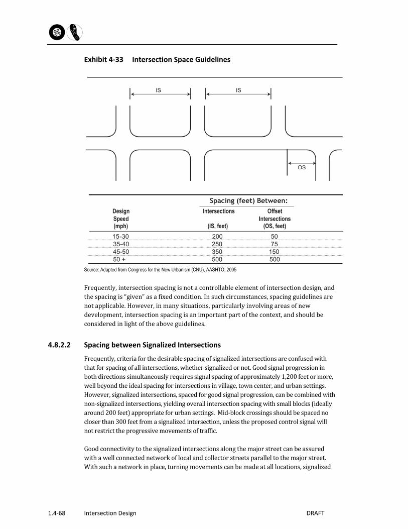
1.4‐68 Intersection Design DRAFT
Exhibit 4‐33 Intersection Space Guidelines
Source: Adapted from Congress for the New Urbanism (CNU), AASHTO, 2005Frequently,intersectionspacingisnotacontrollableelementofintersectiondesign,andthespacingis“given”asafixedcondition.Insuchcircumstances,spacingguidelinesarenotapplicable.However,inmanysituations,particularlyinvolvingareasofnewdevelopment,intersectionspacingisanimportantpartofthecontext,andshouldbeconsideredinlightoftheaboveguidelines.
4.8.2.2 Spacing between Signalized Intersections
Frequently,criteriaforthedesirablespacingofsignalizedintersectionsareconfusedwiththatforspacingofallintersections,whethersignalizedornot.Goodsignalprogressioninbothdirectionssimultaneouslyrequiressignalspacingofapproximately1,200feetormore,wellbeyondtheidealspacingforintersectionsinvillage,towncenter,andurbansettings.However,signalizedintersections,spacedforgoodsignalprogression,canbecombinedwithnon‐signalizedintersections,yieldingoverallintersectionspacingwithsmallblocks(ideallyaround200feet)appropriateforurbansettings.Mid‐blockcrossingsshouldbespacednocloserthan300feetfromasignalizedintersection,unlesstheproposedcontrolsignalwillnotrestricttheprogressivemovementsoftraffic.Goodconnectivitytothesignalizedintersectionsalongthemajorstreetcanbeassuredwithawellconnectednetworkoflocalandcollectorstreetsparalleltothemajorstreet.Withsuchanetworkinplace,turningmovementscanbemadeatalllocations,signalized

Section 1 – Chapter 4
Intersection Design 1.4‐69
andunsignalized,duringnon‐peakhours.Duringpeakhours,motoristsandbicyclistswantingtoenterorcrossthemajorstreetcanchoosetousethesignalizedintersections.
4.8.3 Transit Stop Considerations
Fromthepointofviewofbusoperations,itisdesirabletohavebusstopslocatednearintersectionssothatbusriderscanapproacheasilyfromboththestreetcarryingthebusrouteandfromtheminorstreets.Further,itisdesirabletointegratebusstopswiththeadjoiningpedestriansystem(sidewalks,sharedusepathsandcrosswalks)andalsowithanyadjoiningbikepath/lanesystem.Withrespecttointersections,busandothertransitstopsmaybeeither:
Nearside,locatedontheapproachlegoftheintersection;or,
Farside,locatedonthedeparturelegoftheintersection.
Busandothertransitstopsatintersections,whileadvantageousforbusservice,createchallengesforothervehicleflows,aswellasnon‐motorizedtravel:
Ifthebusstopisinitsownlane(typicallyanextensionofparkinglanestowardtheinterioroftheblock),itmustreenterthetrafficstreamaftercompletingastop.If,ontheotherhand,thebusstopsinalaneoftraffic,itblocksthatlaneforthedurationofthestop.
Atfar‐sidestops,astoppedbusmaycausefollowingvehiclestobackupthroughtheintersection.
Atnear‐sidestops,wherethestoppedbusisoutsidethetrafficstream,thereentryofthebusintothetrafficstreamislikelytooccuratapedestriancrosswalk.Atunsignalizedlocations,thispresentsavehicle/pedestrianconflictpossibility.Evenatsignalizedintersections,busdriversmaybegintheirexitfromtheirloadingspaceduringtheredsignalphase,thusconflictingwithcrossingpedestrians.
Busstopsandaccessibleon‐streetparkingwillcompeteforthelocationnearesttheintersection.Thelocationsofbothshouldberesolvedwithinputfromthelocaldisabilitycommission,regionalindependentlivingcenter,andtransitagency.
Thechallengesassociatedwithbusstopsatintersectionsareaddressedthroughthefollowingdesignguidelines:
Far‐sidebusstopsaregenerallypreferabletonear‐sidestops.
Itisdesirabletoseparatebusloadingareasfrommovinglanesoftraffic.Whereon‐streetparkingisgenerallypresentonthestreet,suchaloadingareacanbegainedbyrestrictingtheparkinginthevicinityoftheintersection.Onstreetswithouton‐streetparking,busbaysmaybeconsidered.

1.4‐70 Intersection Design DRAFT
Parkingshouldberestrictedforadistanceof60feetfromthebeginningofthepavementcornerradius.Thedesignatedbusloadingareashouldnotextendcloserthan20feettothepavementcornerradius.Thesedimensionsapplytobothnear‐sideandfar‐sidebusstops.
Buspullouts,undersomecircumstances,maybeappropriateatintersectionareas.However,thedrawbackofpullouts—difficultyforthebusinreenteringthetrafficstream—canbeproblematicnearintersections.Pulloutsaremorelikelytobeacceptableatfar‐sidestops,wheretheexitingbusvehicleismorelikelytoencounteracceptablegapsinthetrafficstream,comparedtoanear‐sidestopontheapproachlegoftheintersection.BuspulloutsonStateroadwaysshouldbeconsistentwiththeCTDepartmentofTransportation’sHighwayDesignManual.
4.8.4 Mid‐Block Path Crossings
Atintersections,sharedusepaths(forpedestrians,bicyclistsandothernon‐motorizedusers)areaccommodatedasintersectioncrosswalks,asdescribedinSection4.7.8.Wherepathscrossstreetsatlocationsotherthanatintersections,theyshouldconformtothefollowingguidelinesfor“mid‐block”crossings(theMUTCDprovidesfurtherguidanceonplacementandspacing):
Mid‐blockpathcrossingsshouldbeusedonlywhereneeded.Factorslikelytoproducethisneedareexistingrouteofpaths,availabilityofright‐of‐wayforpathextensions,distancetoalternatecrossinglocationsatintersections,andtopography.
Mid‐blockpathcrossingsshouldbeinstalledonlywherestoppingsightdistanceisfullyadequateforvehiculartrafficonthestreetbeingcrossed.
Mid‐blockpathcrossingsshouldprovideadequatesightdistanceforpedestrians,bicyclesandotherusersofthepath.
Wheremid‐blockpathcrossingsexceed60feetinlength,amedianislandshouldbeconsidered.Medianislandsprovidethedualbenefitofprovidingarefugeforcrossingpathusers,reducingthesizeofgapintrafficneededtocrossthestreetsafely,andmayhelpalertapproachingmotoristsandbicycliststothepresenceofthecrossing.
Medianislandsshouldbeatleast6feetwide,toshieldbicyclesormorethanonepedestrian.
Treesalongtheroadsideatthepathcrossing,andinlargermedians,cancallattentionofon‐comingmotoriststothepresenceofthetrailcrossing.However,treesandotherlandscapingshouldnotbeallowedtoinfringeonthesightdistanceofpedestriansormotoristsinthevicinityofthecrossing.
Allmedianorchannelizingislandsshouldhavepedestriancurbcutrampsorat‐gradecut‐throughs.At‐gradecut‐throughsshouldbeslopedgently(maximumof2percentinthebuildconditionand1.5%indesign))toallowdrainage.

Section 1 – Chapter 4
Intersection Design 1.4‐71
Onmulti‐lanearterialstreets,pedestriancallbutton‐actuatedtrafficsignalsmaybeappropriate.Wheninstalled,suchsignalinstallationsshouldhaveasupplementarycallbuttonatthemedian,aswellasateithercurb.TheFederalAccessBoard’scurrentreviseddraftversion(2005)oftheADAAccessibilityGuidelinesforPublicRight‐of‐way(notadoptedatthetimeofthisGuidebook)requiresaudibletrafficsignalswhereverwalksignalsareinstalled.Althoughnotyetrequired,these,alongwithdetectablewarnings,willprovidestrongcuesforpeoplewithlimitedsight.
Pedestriancallbuttonsshouldhavelocatortonesforpedestrianswithlimitedsight.
Pathsshouldbemarkedbywhitecontinentalcrosswalkmarkings(longitudinalstripes).
On‐streetparkingshouldberemovedforadistance(typically40to60feet)adequatetoassuresightdistanceforpathuserswaitingonthecurb.
Analternativetreatmentwhereparkingispresentistoprovideacurbextension,typically6feetdeepfora7to8footparkinglane.Curbextensionsreduceoreliminatetheneedforremovingparking,anddecreasethecrossingdistanceforthepath.
Atcrossingswithmarginalsightdistance,advancesigningorevenadvanceflashingindicatorsmaybeappropriate.
4.8.5 Railroad‐Highway Grade Crossings
Thefollowingguidelinesaffectthehorizontalalignmentofstreetsatarailroad‐highwaygradecrossing:
Crossingsshouldbeavoidedonbothhighwayandrailroadcurves.Railroadcurvespresentaproblemofsuperelevatedtrackcrossingtheroadway.Acurveonthecrossinghighwaypreventsanysuperelevationonthehighway,resultinginanawkwardorunsafecurve.
Thehighwayshouldintersecttracksasnearaspossibleto90degrees.
Ideally,thereshouldnotbenearbyintersectionswithstreetsordriveways.Whereitisnotpossibletoprovidesufficientdistancebetweenthecrossingandnearbyintersections,trafficsignalsatthenearbyintersectioncanbeinterconnectedwiththegradecrossingsignal,toenablevehiclestoclearthegradecrossingasatrainapproaches.
Thecrossingshouldbewideenoughtopermitbicycliststocrossthetracksatrightangles,whilestayingintheirtrafficlane.
Thefollowingguidelinesapplytotheverticalalignmentofstreetsatrailroadhighwaygradecrossings:

1.4‐72 Intersection Design DRAFT
Thestreetsurfaceshouldbeatthesameplaneasthecross‐slopeofthetopoftherails(levelfortangentrailandadoptingthegradeofsuper‐elevatedrail)foradistanceof2feetoutsideeitherrail.Beyondthispoint(i.e.,2feetfromoutsideedgeofrail),thegradeshouldnotbemorethan1percentgreaterthanthegradeacrossthetracks.
Verticalcurvesshouldbeusedtomakethetransitionfromthestreetgradetotherailcross‐slopeplanedescribedabove.
Trafficcontroldevicesforrailroad‐highwaygradecrossingsrangefrompassive(signs,pavementmarkings)toactive(flashinglightsignals)torestrictive(automaticgates).ConsulttheMUTCDfordetailedcriteriaforthedesignandoperationofthesedevices.Atcrossingsprotectedbyactivesignalsorgates,thesightdistancerequirementisdeterminedbythedesignspeedofthecrossingstreet(seeChapter2ofthisGuidebook).AtgraderailcrossingsshouldbeconsistentwiththeDepartmentofTransportation’sHighwayDesignManual.Atcrossingswithouttrainactivatedwarningdevices,thesightdistancemustallowthedriverorbicyclisttoobservetheapproachingtrainatsufficientdistancetopermitstoppingpriortoreachingthecrossing.Thedistanceneededforthiscasedependsonthespeedofthevehicleandthespeedofthetrain.DetailedsightdistancesaregivenfortheWB‐65designvehicleintheAASHTOGreenBook.Wherepublicsidewalkscrossrailsystemsat‐grade,thesurfaceofthecontinuouspassageshallbelevelandflushwiththerailtopattheouteredgeandbetweentherails.
4.8.6 Driveways
Drivewaysarepointsofaccessfrompublicstreetstoprivateproperty,andarethereforenotintersections,asdefinedinthischapter,althoughsomelargevolumedrivewaysshouldbedesignedasintersections.GuidelinesfordrivewaydesignandspacingareofferedinChapter7.
4.9 For Further Information
HighwayCapacityManual,TransportationResearchBoard,Washington,D.C.,2010.
ManualonUniformTrafficControlDevices,FederalHighwayAdministration,2009.
APolicyonGeometricDesignofHighwaysandStreets,AASHTO,2011.
Roundabouts:AnInformationalGuide,FederalHighwayAdministration,2010.
GuideforthePlanning,DesignandOperationofPedestrianFacilities,AmericanAssociationofStateHighwayandTransportationOfficials(AASHTO),2004.

Section 1 – Chapter 4
Intersection Design 1.4‐73
GuidefortheDevelopmentofBicycleFacilities,AmericanAssociationofStateHighwayandTransportationOfficials(AASHTO),2012
UrbanBikewayDesignGuide,NACTO,2011.
ADAAccessibilityGuidelinesforBuildingsandFacilities,TheAccessBoard,amendedthroughAugust2005.
GuidelinesforDrivewayLocationandDesign,InstituteofTransportationEngineers(ITE),1987.