Types of intersection of road and design parameters of road intersection

6. Intersection Design
6. INTERSECTION DESIGN INTRODUCTION ............................................................................................................................... 1
ESSENTIAL PRINCIPLES OF INTERSECTION DESIGN ......................................................................... 1
INTERSECTION GEOMETRY ............................................................................................................. 2
Intersection Skew ........................................................................................................................ 3
Corner Radii ................................................................................................................................ 4
Curb Extensions .......................................................................................................................... 7
Crosswalk and Ramp Placement ............................................................................................... 10
On‐Street Parking Near Intersections ....................................................................................... 13
Right‐Turn Channelization Islands ............................................................................................ 13
YIELD AND STOP CONTROLLED INTERSECTIONS .......................................................................... 16
SIGNALIZED INTERSECTIONS ......................................................................................................... 16
Operational Design ................................................................................................................... 17
Phasing ...................................................................................................................................... 17
ROUNDABOUTS ............................................................................................................................. 22
Advantages and Disadvantages ................................................................................................ 23
General Design Elements of Roundabouts ............................................................................... 24
Roundabout Design Criteria ...................................................................................................... 25
Operations and Analysis ........................................................................................................... 26
Single‐Lane Roundabouts ......................................................................................................... 26
Multi‐Lane Roundabouts .......................................................................................................... 27
Mini‐Roundabouts .................................................................................................................... 28
Neighborhood Traffic Circles .................................................................................................... 29

6. Intersection Design
(Credit: Kimley‐Horn and Associates, Inc.)

INTROD
trains. TIntersectof confliintersectfor safetusers is pthe comm This chasignalizatmobility appropri
ESSENT The folloserve all
G
M
U
Ao
Sa
F
Li
Bro
DUCTION
The diverse tions have thcts betweentions. This chty. Designingperformed omunity objec
apter descrtion, as welfor all userate use and
TIAL PRINC
owing interusers of inte
Good interse
Minimize con
Unusual conf
Accommodatf service.
imple right‐are worsened
ree‐flowing
ively intersectio
oward Comp
uses of inthe unique chn all modesharacteristicg multimodon a case‐by‐ctives and p
ibes designl as roundars. The bendesign of ea
CIPLES OF I
rsection desersections:
ction design
nflicts betwe
flicts should
te all modes
angle intersd at skewed
movements
on (Credit: Dan
plete Streets
tersections haracteristics, and mostc is the basisal intersecti‐case basis. Triorities rela
n consideratbouts and onefits and cach feature a
NTERSECT
sign princip
ns are compa
een modes.
be avoided.
s with appro
ections are and multi‐le
s should be a
n Burden)
s Guidelines
Most cointersecother’s indicatewhat tExceptioare lowshared intersecpedestrto theirreducedintersecbicycles
involve a hc of accommt collisions for most inions with thThe designeated to desig
tions in inother featuronstraints oare describe
TION DESIG
ples apply t
act.
opriate leve
best for all egged inters
avoided.
s • Chapter 6
onflicts betwctions, whe
path. Ges to those ahey must dons to this i
w (typically lespace desigctions withrians and bicr greater vud visibility tctions ops, cars, busehigh level o
modating theon major ttersection dhe approprier should beggn tradeoffs.
tersection res to improof each feated.
GN
to
els
users since ections.
“Busyto cro
‐
6, Page 6‐1
ween roadwere traveleGood interapproachingdo and whinclude placess than 20 gn causes ush caution.cyclists are ulnerability, to other userate wites, trucks, anof activity ae almost conthoroughfaredesign standate accommgin with an .
geometry aove safety, ature are ex
many inters
y streets aoss." (Broward survey resp
6. Interse
ay users occers cross rsection dg the interseho has to yes where spmph) or whsers to appr Conflicts exacerbatedlesser size,
sers. Multimh pedestnd in some cand sharedstant occurres take placards, particumodations founderstandi
and interseaccessibilityxamined and
section prob
are not fr
Complete pondent)
ection Design
cur at each esign ection yield. peeds ere a roach
for d due , and modal rians, cases, use.
rence ce at ularly or all ing of
ection , and d the
blems
riendly
Streets
n

6. Intersection Design
Broward Complete Streets Guidelines • Chapter 6, Page 6‐2
Avoid elimination of travel modes from the typical section due to intersection design constraints.
Access management practices should be used to remove additional vehicular conflict points near the intersection.
Signal timing should consider the safety and convenience of all users and should not hinder bicycle or foot traffic with overly long waits or insufficient crossing times.
Ensure intersections are fully accessible.
INTERSECTION GEOMETRY Intersection geometry is a critical element of intersection design, regardless of the type of traffic control used. Geometry sets the basis for how all users traverse intersections and interact with each other. The principles of intersection geometry apply to both street intersections and freeway on‐ and off‐ramps. Intersection layout is primarily comprised of the alignment of the legs; width of traffic lanes, bicycle lanes, and sidewalks on each approach (number of lanes, median and roadside elements); and the method of treating and channelization of turning movements. The design of an intersection’s layout requires a balance between the needs of pedestrians, bicyclists, vehicles, freight and transit in the available right‐of‐way.
Intersections should be designed to serve all types of users comfortably, even on wide arterial boulevards (Credit: Kimley‐Horn and Associates, Inc.)

6. Intersection Design
Broward Complete Streets Guidelines • Chapter 6, Page 6‐3
Intersections are comprised of a physical area. The functional area is where drivers make decisions and maneuver into turning movements. The three parts of a functional area include the perception‐reactions distance, maneuver distance and storage distance. AASHTO’s Policy on Geometric Design of Highways and Streets, addresses the issues and provides guidance for the detail geometric design of the functional area. The basic types of intersections in urban contexts include the T‐intersection, cross intersection, multi‐leg intersection, and modern roundabout.
INTERSECTION SKEW Skewed intersections are generally undesirable and introduce the following complications for all users:
The travel distance across the intersection is greater, which increases exposure to conflicts and lengthens signal phases for pedestrians and vehicles.
Skews require users to crane their necks to see other approaching users, making it less likely that some users will be seen.
Obtuse angles encourage speeding. To alleviate the problems with skewed intersections, several options are available:
Every reasonable effort should be made to design or redesign the intersection closer to a right angle. Some right‐of‐way may have to be purchased, but this can be offset by the larger area no longer needed for the intersection, which can be sold back to adjoining property owners or repurposed for a pocket park, rain garden, greenery, etc.
Converting stop‐controlled and signalized intersections into modern roundabouts. Roundabouts’ benefits include improved safety, speed reduction, aesthetics and operational functionality and capacity.
Pedestrian refuges should be provided if the crossing distance exceeds approximately 40 feet.
General use travel lanes and bike lanes may be striped with dashes to guide bicyclists and motorists through a long undefined area.

6. Intersection Design
Broward Complete Streets Guidelines • Chapter 6, Page 6‐4
Realigning the skewed intersection in the graphic on the left to the right‐angle connection in the graphic on the
right results in less exposure distance and better visibility for all users. (Credit: Michele Weisbart)
Multi‐leg intersections (more than two approaching roadways) are generally undesirable. Making it clear to drivers that pedestrians use the intersections, and providing proper indication to pedestrians where the best place is to cross are some or the problems with this type of intersections. Multi‐leg intersections also present the following complications for all users:
Multiple conflict points are added as users arrive from several directions.
Users may have difficulty assessing all approaches to identify all possible conflicts.
At least one leg will be skewed.
Users must cross more lanes of traffic and the total travel distance across the intersection is increased.
To alleviate the problems with multi‐leg intersections, several options are available:
Every reasonable effort should be made to design the intersection so there are no more than four legs. This is accomplished by removing one or more legs from the major intersection and creating a minor intersection further up or downstream.
As an alternative, one or more of the approach roads can be closed to motor vehicle traffic, while still allowing access for pedestrians and bicyclists.
Roundabouts should be considered.
Pedestrian refuges should be created if the crossing distance exceeds approximately 40 feet.
General use travel lanes and bike lanes may be striped with dashes to guide bicyclists and motorists through a long undefined area.
CORNER RADII Corner radii (also called curb return radii) are the curved connection of curbs in the corners. This intersection geometry feature has a significant impact on the comfort and safety of non‐

6. Intersection Design
Broward Complete Streets Guidelines • Chapter 6, Page 6‐5
motorized users. The use of the smallest practical corner radii to shorten the length of the crosswalk is usually desirable. Small corner radii provide the following benefits:
Smaller, more pedestrian‐scale intersections resulting in shorter crossing distances
Slower vehicular turning speeds
Reduced pedestrian crossing distance and crossing time
Better geometry for installing perpendicular ramps for both crosswalks at each corner
Simpler, more appropriate crosswalk placement, in line with the approaching sidewalks
Tighter corner radii reduce crossing distance and slow turning traffic.
(Credit: Michele Weisbart)
6. Intersection Design
Broward Complete Streets Guidelines • Chapter 6, Page 6‐6
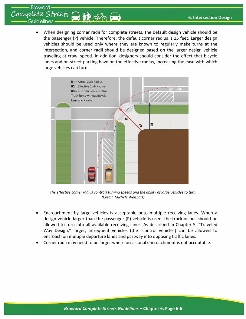
When designing corner radii for complete streets, the default design vehicle should be the passenger (P) vehicle. Therefore, the default corner radius is 15 feet. Larger design vehicles should be used only where they are known to regularly make turns at the intersection, and corner radii should be designed based on the larger design vehicle traveling at crawl speed. In addition, designers should consider the effect that bicycle lanes and on‐street parking have on the effective radius, increasing the ease with which large vehicles can turn.
The effective corner radius controls turning speeds and the ability of large vehicles to turn.
(Credit: Michele Weisbart)
Encroachment by large vehicles is acceptable onto multiple receiving lanes. When a design vehicle larger than the passenger (P) vehicle is used, the truck or bus should be allowed to turn into all available receiving lanes. As described in Chapter 5, “Traveled Way Design,” larger, infrequent vehicles (the “control vehicle”) can be allowed to encroach on multiple departure lanes and partway into opposing traffic lanes.
Corner radii may need to be larger where occasional encroachment is not acceptable.

6. Intersection Design
Broward Complete Streets Guidelines • Chapter 6, Page 6‐7
Corner radii can be kept smaller by allowing trucks and buses to turn into multiple receiving lanes. (Credit: Michele Weisbart)
CURB EXTENSIONS Where on‐street parking is allowed, curb extensions (also called bulb‐outs) should replace the parking lane at crosswalks. Curb extensions should be the same width as the parking lane. The appropriate corner radius should be applied based on the guidance in the section above. Due to reduced road width, the corner radius on a curb extension may need to be larger than if curb extensions were not installed. Curb extensions offer many benefits related to livability:
Reduced pedestrian crossing distance resulting in less exposure to vehicles and shorter pedestrian clearance intervals at signals
Improved visibility between pedestrians and motorists
A narrowed roadway, which has a potential traffic calming effect
Additional room for street furniture, landscaping, and curb ramps
Slower turning vehicles
Additional on‐street parking potential due to improved sight lines at intersections. Since curb extensions allow pedestrians to walk out toward the edge of the parking lane without entering the roadway, pedestrians can better see vehicles and motorists can better see pedestrians.
Management of streetwater runoff
Separate parking maneuvers from turning vehicles.

6. Intersection Design
Broward Complete Streets Guidelines • Chapter 6, Page 6‐8
To fully achieve livability goals, the curb extension and parking area can be integrated into the furniture zone portion of the sidewalk corridor. This technique involves using similar surface materials for the curb extension, parking area, and the sidewalk as shown in the figure below. Instead of the curb extensions appearing to jut out into the street, the parking appears as “parking pockets” in the furniture zone. Curb extensions can be used in any context zone, but they should be standard in T‐5 and T‐6. Curb extensions must always be outside of the width of the bike lane or the location within the traveled way that bicyclists are expected to ride.
Curb extensions improve sight distance between pedestrians and motorists, possibly allowing additional on‐street parking.
(Credit: Michele Weisbart)

6. Intersection Design
Broward Complete Streets Guidelines • Chapter 6, Page 6‐9
Integrating curb extensions and on‐street parking into the sidewalk corridor enhances pedestrian safety and the walking experience. (Credit: Michele Weisbart)
To reinforce this design where street grades permit, the gutter line and drainage grates should be placed between the travel lane and the parking lane/curb extensions. This is called a “valley gutter” and creates a stronger visual cue separating the parking lane from the bicycle lane or travel lane. It can sometimes allow existing drainage infrastructure to be left in place.
An example of integrating curb extensions and parking into the sidewalk corridor by
placing a valley gutter between the parking and the traveled way. (Credit: Michele Weisbart)

6. Intersection Design
Broward Complete Streets Guidelines • Chapter 6, Page 6‐10
CROSSWALK AND RAMP PLACEMENT Crosswalks are used to assist pedestrians in crossing the street. Florida State Statute 316
makes it clear that unmarked crosswalks can exist only at intersections whereas marked
crosswalks can exist at intersections or elsewhere. This is consistent with the Manual on
Uniform Traffic Control Devices (MUTCD). Crosswalks and ramps at intersections should be
placed so they provide convenience and safety for pedestrians. The following recommended
practices will help achieve these goals:
Allow crossings on all legs of an intersection, unless there are no pedestrian accessible
destinations on one or more of the corners. Closing a crosswalk usually results in a
pedestrian either walking around several legs of the intersection, exposing them to
more conflicts, or crossing at the closed location, with no clear path or signal indication
as to when to cross.
Provide marked crosswalks at signalized intersections.
Provide marked crosswalks at an intersection approach controlled by stop sign.
Marked crosswalks shall be 10 feet wide in urban zones.
Strongly consider providing marked crosswalks at major unsignalized intersections with
medians for pedestrian refuges or on one‐way streets.
Place crosswalks as close as possible to the desire line of pedestrians, which is generally
in line with the approaching sidewalks.
Provide as short as possible a crossing distance to reduce the time that pedestrians are
exposed to motor vehicles; this is usually as close as possible to right angles across the
roadway, except for skewed intersections.
Ensure that there are adequate sight lines between pedestrians and motorists. This
typically means that the crosswalks should not be placed too far back from the
intersection.
When a raised median is present, extend the nose of the median past the crosswalk
with a cut‐through for pedestrians.
Provide one ramp per crosswalk (two per corner for standard intersections with no
closed crosswalks). Ramps must be entirely contained within a crosswalk (the crosswalk
can be flared to capture a ramp that cannot be easily relocated). Align the ramp run
with the crosswalk when possible, as ramps that are angled away from the crosswalk
may lead some users into the intersection.

6. Intersection Design
Broward Complete Streets Guidelines • Chapter 6, Page 6‐11
At intersections where roads are skewed or where larger radii are necessary for trucks,
it can be difficult to determine the best location for crosswalks and sidewalk ramps. In
these situations, it is important to balance the recommended practices above. Tighter
curb radii make implementing these recommendations easier.
At signalized crossings, shared‐use path crossing, or any other particular high emphasis crosswalk markings (ladder style crosswalk) should be used to increase visibility.
Curb ramp opening on shared‐use path shall be the same width as the path itself.
Detectable warning surfaces shall be provided per MUTCD 3B.18 and 49 Code of Federal Regulations Part 37.
Pedestrian warning sign (W11‐2) at a high emphasis crosswalk. Note the yield bars (series of isosceles triangles
painted on the approach to the crosswalk. (Credit: Kimley‐Horn and Associates, Inc.)

6. Intersection Design
Broward Complete Streets Guidelines • Chapter 6, Page 6‐12
One curb ramp per crosswalk should be provided at corners. Ramps should align with sidewalks and crosswalks. (Credit: Michele Weisbart)

6. Intersection Design
Broward Complete Streets Guidelines • Chapter 6, Page 6‐13
ON‐STREET PARKING NEAR INTERSECTIONS On‐street parking should be positioned far enough away from intersections based on providing adequate sight distance to allow for good visibility of pedestrians preparing to cross the street. Curb extensions allow parking to be placed closer to the intersection since pedestrians can queue in a more visible location for which parked cars do not block the sight line of an oncoming motorist.
RIGHT‐TURN CHANNELIZATION ISLANDS In the context suburban zone (T3) through urban core zone (T6), high speed channelized right‐
turns are inappropriate because they create conflicts with pedestrians. Right‐turn lanes should
generally be avoided as they increase the size of the intersection, the pedestrian crossing
distance, and the likelihood of right‐turns‐on‐red by inattentive motorists who do not notice
pedestrians on their right. However, where there are heavy volumes of right turns
(approximately 200 vehicles per hour or more), a right‐turn lane may be the best solution to
provide additional vehicle capacity without adding additional lanes elsewhere in the
intersection. For turns onto roads with only one through lane and where truck turning
movements are rare, providing a small corner radius at the right‐turn lane often provides the
best solution for pedestrians’ safety and comfort.
At intersections of multi‐lane roadways where trucks make frequent right turns, a raised
channelization island between the through lanes and the right‐turn lane is a good alternative to
an overly large corner radius and enhances pedestrian safety and access. If designed correctly,
a raised island can achieve the following objectives:
Allow pedestrians to cross fewer lanes at a time
Allow motorists and pedestrians to judge the right turn/pedestrian conflict separately
Reduce pedestrian crossing distance, which can improve signal timing for all users
Balance vehicle capacity and truck turning needs with pedestrian safety
Provide an opportunity for landscape and hardscape enhancement
The following design practices for right‐turn lane channelization islands should be used to
provide safety and convenience for pedestrians, bicyclists, and motorists:
The provision of a channelized right‐turn lane is appropriate only on signalized
approaches where right‐turning volumes are high or large vehicles frequently turn and
conflicting pedestrian volumes are low .
Provide accessible islands for refuge.
Provide a yield sign for the channelized right‐turn lane.
Tighter angles are preferred for multiple reasons.

6. Intersection Design
Broward Complete Streets Guidelines • Chapter 6, Page 6‐14
Provide at least a 60‐degree angle between vehicle flows, which reduces turning speeds
and improves the yielding driver’s visibility of pedestrians and vehicles.
Place the crosswalk across the right‐turn lane about one car length back from where
drivers yield to traffic on the other street, allowing the yielding driver to respond to a
potential pedestrian conflict first, independently of the vehicle conflict, and then move
forward, with no more pedestrian conflict.
If vehicle‐pedestrian conflicts are a significant problem in the channelized right‐turn
lane, it might be appropriate to provide signing to remind drivers of their legal
obligation to yield to pedestrians crossing in the crosswalk. Regulatory signs such as the
R10‐15 sign from the MUTCD or warning signs such as the W11‐2 sign could be placed in
advance of or at the crossing location.
Removing channelized right‐turn lanes further assists pedestrians.
These goals are best accomplished by creating an island that is roughly twice as long as it is
wide. The corner radius will typically have a long radius (150 feet to 300 feet) followed by a
short radius (20 feet to 50 feet). When creating this design, it is necessary to allow large trucks
to turn into multiple receiving lanes. This design is often not practical for right‐turn lanes onto
roads with only one through lane. This right‐turn channelization design is different from designs
that provide free‐flow movements (through a slip lane) where right‐turning motorists turn into
an exclusive receiving lane at high speed. Right turns should be signal‐controlled in this
situation to provide for a signalized pedestrian walk phase.
This TURNING TRAFFIC MUST YIELD TO PEDESTRIANS AND BICYCLISTS sign is an R10‐15 (modified). The modification is for use on shared‐use paths.
(Credit: Kimley‐Horn and Associates, Inc.)

6. Intersection Design
Broward Complete Streets Guidelines • Chapter 6, Page 6‐15
Traffic channelization is an effective mitigation strategy when intersection radii reduction is not an option.
(Credit: Michele Weisbart)
Sharper angles of slip lanes are important to slow cars and increase visibility (Credit: Michele Weisbart)

6. Intersection Design
Broward Complete Streets Guidelines • Chapter 6, Page 6‐16
YIELD AND STOP CONTROLLED INTERSECTIONS Unsignalized intersection control options include the following:
Yield control, which is under‐utilized and should be considered to reduce unnecessary stops caused by the overuse of STOP signs.
Uncontrolled intersections are yield controlled by default.
Two‐way stop control, which is the most common form of intersection control. This is an overused device. At many intersections a neighborhood traffic calming circle is a preferable and more effective option.
All‐way stops are often overused, incorrectly, to slow traffic. The use of all‐way stops should be consistent with the MUTCD. At many intersections a neighborhood traffic calming circle is a preferable and a more effective option.
Crosswalks may be marked consistent with Florida State Statute 316.
SIGNALIZED INTERSECTIONS Signalized intersections provide unique challenges and opportunities for livable communities and complete streets. On one hand, signals provide control of pedestrians and motor vehicles with numerous benefits. Where signalized intersections are closely spaced, signals can be used to control vehicle speeds by providing appropriate signal progression on a corridor. Traffic signals allow pedestrians and bicyclists to cross major streets with only minimal conflict with motor vehicle traffic. On the other hand, traffic signals create challenges for non‐motorized users. Signalized intersections often have significant turning volumes, which conflict with concurrent pedestrian and bicycle movements. In many cases, roundabouts offer safer, more convenient intersection treatment than signals. To improve livability and pedestrian safety, signalized intersections should meet the following principles:
Provide signal progression at speeds that support the target speed of a corridor whenever feasible
Provide short signal cycle lengths, which allow frequent opportunities to cross major roadways, improving the usability and livability of the surrounding area for all modes
Ensure that signals detect bicycles through video detection zones for video monitoring or loop detectors in‐pavement.
Place pedestrian signal heads in locations where they are visible
At locations with many crossing pedestrians, time the pedestrian phase to be on automatic recall, so pedestrians don’t have to seek and push a pushbutton.
Where few pedestrians are expected and automatic recall of walk signals is not desirable, place pedestrian pushbuttons in convenient locations, using separate pedestals if necessary. Use the recommendations regarding pushbutton placement for

6. Intersection Design
Broward Complete Streets Guidelines • Chapter 6, Page 6‐17
Pole‐mounted signal (Credit: Ryan Snyder)
accessible pedestrian signals found in the Manual on Uniform Traffic Control Devices (MUTCD).
Include pedestrian signal phasing that increases safety and convenience for pedestrians, as discussed in more detail below.
OPERATIONAL DESIGN Approximately 2 percent of intersections are signalized, and approximately 20 percent of all intersection crashes occur at signalized intersections. Unfortunately, in many locations signalization is the only option because of right‐of‐way limitations, high vehicle volumes, and the need to create gaps to provide reasonable operation for all users.
Over the years, the most common signal hardware has transitioned from post‐mounted signals to span‐wire signals to overhead mast arms. This change has lifted drivers’ eyes upward and created a situation in many east/west streets where drivers must look toward a rising or setting sun that can block vision of a signal. In urban areas the large mast arms are intrusive. As part of the conversion to healthier streets, changing to post‐mounted signals in urban areas could lower the cost of installing and maintaining signals, reduce the vision intrusion, and help lower a driver’s vision back to pedestrians. There are two primary advantages for pedestrians and bicyclists
to pole‐mounted signals:
Drivers have to stop back from the crosswalk to see the indication so they are less likely to encroach into the crosswalk, and more likely to see pedestrians and bicyclists when turning right.
Mast‐arm signals encourage higher speeds since drivers can see several in a row. If they are green, drivers are more likely to accelerate. But pole‐mounted signals are only visible to drivers closer to the intersection, causing them to drive slower on the approach.
PHASING A signal phase is defined as the cycle length allocated to a traffic movement at an intersection receiving the right‐of‐way, or to any combination of traffic movements receiving the right of way simultaneously. The combination of all phases is equal to one cycle length.

6. Intersection Design
Broward Complete Streets Guidelines • Chapter 6, Page 6‐18
Basic Signal Timing The “timing” is the time in seconds allocated to various vehicular and pedestrian movements. A traffic control signal transmits information to the users by selective illumination of different color lights at a signalized intersection. The illuminated color indicates the user should take a specific action at the signalized intersection:
Green phase. Green phase is when motorists and bicyclists may proceed through the intersection.
Yellow phase. Yellow phase is the cycle phase before changing to the red interval that prohibits traffic movement. It signifies to users the light is about to turn red and they should stop if they can safely do so, or continue proceeding if that is safer. A properly timed yellow time interval is important to reduce signal violations by users passing through the intersection.
All‐red phase. All‐red phase is that portion of a traffic cycle time where all vehicles are prohibited from any movements at the intersection. The all‐red time follows the yellow time interval and precedes the next green interval. The purpose of the all‐red time is to allow vehicles that entered the intersection late during the yellow time to clear the intersection before the traffic signal displays green time for conflicting approaches.
Left‐Turn Phasing The most commonly used “left turn” phases at an intersection with a left‐turn lane are
Permissive. Under permissive left turn phasing, through traffic may proceed straight through the intersection with a circular green signal indication, as side traffic is stopped (with a circular red signal indication); the left turning vehicles are permitted to make the turn when they find a safe and adequate gap from the approaching vehicles. Permissive left turn phases create conflicts with pedestrians crossing the street as the timing puts the two on a collision course.
Protected‐permissive. Under protected‐permissive left turn phasing, left turns are allowed to pass the intersection with a green arrow first during the protected phase (opposing through traffic is stopped); usually three to five vehicles are allowed in the cycle before the left turn is changed from a left arrow to a circular green indication, and opposing through traffic is allowed to pass through the intersection. During the permissive phase motorists may turn left while others go straight. Protected‐ permissive
Permissive left‐turn signal (Credit: Michele Weisbart)
Protected‐permissive left‐turn signal
(Credit: Michele Weisbart)
Protected left‐turn signal (Credit: Michele Weisbart)

6. Intersection Design
Broward Complete Streets Guidelines • Chapter 6, Page 6‐19
left turn phases create conflicts with pedestrians crossing the street as the timing puts the two on a collision course, especially with left‐turning drivers who arrived after the left‐turn phase and are impatient to turn left before the signal reverts to red.
Protected only. Under protected left turns, drivers can only turn left with a left‐turn green arrow. The protected left turns can be either “leading” or “lagging.” A leading protected left turn allows left‐turns during the beginning of the cycle. A lagging protected left allows left turns at the end, after opposing through traffic has proceeded. Protected left‐turn phases are preferred to both permissive phases because they eliminate the inherent conflict between left turning vehicles and pedestrians. Protected left turns provide the greatest safety for pedestrians. Permissive phases are typically used to maintain a higher LOS for motorists.
Pedestrian Phasing Basic pedestrian signal timing principles should be combined with innovative pedestrian signal timing techniques to enhance pedestrian safety and convenience. Pedestrian signal heads provide indications exclusively intended for controlling pedestrian
traffic. These signal indications consist of the illuminated symbols of a WALKING PERSON
(symbolizing WALK) and an UPRAISED HAND (symbolizing DON’T WALK). Pedestrian signal head
indications have the following meanings:
A steady WALKING PERSON (WALK) signal indication means that a pedestrian facing the signal indication is permitted to start to cross the roadway in the direction of the signal indication, possibly in conflict with turning vehicles.
A flashing UPRAISED HAND (DON’T WALK) signal indication means that a pedestrian shall not start to cross the roadway in the direction of the signal indication, but that any pedestrian who has already started to cross shall proceed to the far side of the traveled way of the street or highway, unless otherwise directed by a traffic control device to proceed only to a median or pedestrian refuge area.
A steady UPRAISED HAND (DON’T WALK) signal indication means that a pedestrian shall not enter the roadway in the direction of the signal indication.
The text below discusses the timing of each of these indicators.
Walk Interval The WALK interval (clear WALKING PERSON) must typically be a minimum of 7 seconds. However, to provide more convenience for pedestrians, and possibly more safety due to better pedestrian behavior, the WALK interval should be maximized using the following techniques:

Ininthapbco
Exresishacy
Wstmwthsepn
PedestriaThe propedestriaincluded pedestriapedestriainterval second crosswalone curbThis spechildren,MUTCD the WALto be suwalking sthe crossthe bottothat is should bwhere hsuch as
Bro
nstead of pnterval, maxhe availabccomplishededestrian elow) from oncurrent ve
xcept at inteelatively fewignals are sehould be seutomaticallyycle.
Where a majtreet, the Wminor street with the grhrough vehiet to recedestrian deo impact to
an Clearancocedures foan clearancein the MUTan clearancan who lefttraveling atto travel tk length shob ramp to theed allows and ADA uincludes anoK interval pufficient to speed of 3 feswalk, measom of the orequired toe added to igh numbernear senior
oward Comp
providing tximize the Wble green d by subtraclearance the availablehicular mov
ersections ww, and anyet on fixed tet on “recay provided
jor street intWALK intervcan be set reen intervcle movemeall as weelay along tmotor vehic
e Interval or calculatine interval (flTCD, but have interval it the curb at a walkingthe length ould be meae center of s pedestriausers, to cleother test tlus the pedeallow a pe
eet per secosured from opposing rao satisfy ththe walk inrs of slow pcenters, re
plete Streets
he minimuWALK intervinterval.
acting the ninterval (le green timvements.
where pedesywhere thatime, WALKall” so that during eve
tersects a mval for croon recall, coval for theent, which isell. This mthe major stcle capacity.
ng the timashing oranve recently cs calculatedat the end og speed of of the crosured from the opposinans, especiear the intehat requiresestrian clearedestrian trnd to travel the top of mp. Any adhis second terval. In nepedestrians habilitation
s Guidelines
m WALK val within This is
necessary discussed
me for the
trians are at vehicle K intervals they are
ery signal
minor side ssing the oncurrent e parallel s typically minimizes treet with
ming of thnge hand) archanged. Thd to allow of the WAL3.5 feet peosswalk. Ththe center ong curb rampally seniorrsection. Ths the total orance intervaraveling at the length oone ramp tdditional timrequiremeneighborhoodare presencenters, an
• Chapter 6
(
Pe
he re he a LK er he of p. rs, he of al a of to me nt ds nt, nd
6, Page 6‐20
Walk signal (Credit: Sky Yim
edestrian count(Credit: Sk
6. Interse
m)
tdown signals ky Yim)
ection Design
n

6. Intersection Design
Broward Complete Streets Guidelines • Chapter 6, Page 6‐21
disabled centers, the interval should be set for even slower speeds. The MUTCD also requires that countdown pedestrian signals be installed for all pedestrian signals where the pedestrian change interval is more than 7 seconds. These signals count down the pedestrian clearance interval and provide more information to pedestrians, allowing them to more easily adjust their walking patterns to ensure they are out of the crosswalk before the end of the pedestrian clearance interval. Research on pedestrian countdown signals has determined
Pedestrians understand how they work.
Fewer people start walking in the pedestrian clearance interval.
Very few pedestrians are left in the crosswalk during the steady orange hand.
Drivers don’t accelerate to beat the light.
Research in San Francisco shows a 25 percent reduction in all crashes. Other Signal Design Changes for Pedestrians Where appropriate, use signal timing and operations techniques that minimize conflicts with pedestrians and motor vehicles, including the following:
Protected only left‐turn phases.
Leading pedestrian intervals (LPI) where the pedestrian WALK interval is displayed 2 to 5 seconds prior to the concurrent green interval. This enables pedestrians to enter the crosswalk before drivers turn, increasing their visibility to drivers.
Prohibiting right‐turns‐on‐red where there are restricted sight lines between motorists and pedestrians, where there are an unusual number of pedestrian conflicts with turns on red compared to right‐turns‐on‐green, or where a leading pedestrian interval is used.
Signs that remind drivers to yield to pedestrians when turning at signals.
Pedestrian‐user‐friendly‐intelligent (PUFFIN) signals, which detect slower pedestrians in crosswalks and add clearance interval time to the pedestrian signal.
Exclusive Pedestrian Phase, which stop traffic on all legs of the intersection and allow pedestrians to cross diagonally, may be used where turning vehicles conflict with very high pedestrian volumes. Although pedestrians can cross in any direction during the pedestrian phase, pedestrians typically have to wait for both vehicle phases before they get the walk signal again. Exclusive Pedestrian Phase intersections can incorporate a walk phase concurrent with the green phase for pedestrians continuing along a straight path to eliminate this delay.

6. Intersection Design
Broward Complete Streets Guidelines • Chapter 6, Page 6‐22
ROUNDABOUTS Modern roundabouts are low‐speed, compact designs and are not the same as the old, fast, and dangerous high speed rotaries found in the Northeast or the old traffic circles such as Young Circle in Hollywood and DuPont Circle in Washington DC. Modern roundabouts are becoming more widely accepted in the United States. Modern roundabouts are potentially the cheapest, safest, and most aesthetic form of traffic control for many intersections. The Federal Highway Administration states that modern roundabouts reduce fatalities by approximately 90 percent. A roundabout is an intersection design with the following characteristics and features.
Users approach the intersection, slow down, yield and/or stop for pedestrians in a crosswalk, and then enter a circulating roadway, yielding to drivers already in the roundabout. The circulating roadway encircles a central island around which vehicles travel counterclockwise. Splitter islands force drivers to turn right, and provide a refuge for pedestrians. Horizontal deflection encourages slow traffic speeds, but allows movement by trucks. A landscaped visual obstruction in the central island obscures the driver’s view of the road beyond, to discourage users from entering the roundabout at high speeds. The central island should not
include pedestrian attractions, such as benches, because it’s not desirable for pedestrians to walk in or across the roundabout circulating lanes. The central island can vary in shape from a circle to a “square‐a‐bout” in historic areas, ellipses at odd shaped intersections, dumbbell, or even peanut shapes. Each leg of a modern roundabout has a triangular splitter island that provides a refuge for pedestrians, prevents drivers from turning left (the “wrong‐way”), guides drivers through the roundabout by directing them to the edge of the central island, and helps to slow drivers. Roundabouts can range from quite small to quite large, from a central island diameter of about 12 feet for a traffic calming device at a neighborhood intersection to 294 feet to the back of sidewalk on a large multi‐lane roundabout. Modern roundabouts should be designated to reduce the relative speeds between conflicting traffic streams. This section of the chapter briefly describes roundabout application and design information. For more detailed information, refer to NCHRP Report 672, Roundabouts: An Informational Guide, Second Edition.
Acacia Roundabout (Credit: Ken Sides)

6. Intersection Design
Broward Complete Streets Guidelines • Chapter 6, Page 6‐23
ADVANTAGES AND DISADVANTAGES Modern roundabouts reduce vehicle‐to‐vehicle and vehicle‐to‐pedestrian conflicts and, thanks to a substantial reduction in vehicle speeds, reduce all forms of crashes and crash severity. In particular, roundabouts eliminate the most lethal crashes : head on and T‐bone collisions. Other benefits of roundabouts include the following:
Little to no delay for pedestrians, who have to cross only one direction of traffic at a time
Improved accessibility to intersections for bicyclists through reduced conflicts and vehicle speeds
A smaller carbon footprint (no electricity is required for operation and fuel consumption is reduced as motor vehicles spend less time idling and don’t have to accelerate as often from a dead stop)
They work well in South Florida, especially during hurricane season.
The opportunity to reduce the number of vehicle lanes between intersections (e.g., to reduce a five‐lane road to a two‐lane road, due to increased vehicle capacity at intersections)
Little to no stopping during periods of low flow
Significantly reduced maintenance and operational costs because the only costs are related to the landscape
Reduced delay, travel time, and vehicle queue lengths
Lowered noise levels
Less fuel consumption and air pollution
Simplified intersections
Facilitated U‐turns
The ability to create a gateway and/or a transition between distinct areas through landscaping
When constructed as a part of a new road or the reconstruction of an existing road, the cost of a roundabout is minimal and can be cheaper than the construction of an intersection and the associated installation of traffic signals and additional turn lanes
Light rail can pass through the center of a roundabout without delay because rail has the right of way
A possible disadvantage is that sight‐impaired people can have difficulty navigating around large roundabouts. But this can be mitigated with ground level wayfinding devices. Roundabouts are not always the most appropriate solution, it requires location specific analysis. Also roundabouts may not be the best solution near active railroad crossings.

6. Intersection Design
Broward Complete Streets Guidelines • Chapter 6, Page 6‐24
GENERAL DESIGN ELEMENTS OF ROUNDABOUTS Central Island The design of the central island is an important element of a roundabout. In conjunction with well‐designed approach and departure lanes, the central island controls vehicle speeds through deflection and controls the size of vehicles that can pass through and turn at a roundabout. It provides space for landscaping to beautify an intersection or create a focal point or community enhancement, but it also provides space for the inclusion of an uplighted vertical element such as a tree, which is important in providing long range conspicuity of a roundabout.
Single‐lane roundabout (Credit: Michele Weisbart)
Splitter Islands Splitter islands and/or medians on each approach serve several functions. They provide a refuge for pedestrians crossing at the roundabout, breaking the crossing into two smaller crossings. This allows pedestrians to select smaller gaps and cross more quickly. Splitter islands and medians direct vehicles into the circulating lane and limit the ability of drivers to make left turns the wrong way into the circulating roadway. Splitter islands should have a minimum width

6. Intersection Design
Broward Complete Streets Guidelines • Chapter 6, Page 6‐25
of 6 feet, and preferably 8 feet, from the face‐of‐curb to the opposite face‐of‐curb. This width provides a comfortable, safe refuge for groups of pedestrians and pedestrians with bicycles. Truck Apron Because central islands must be made large enough to deflect and hence control the speed of passenger vehicles, they can limit the ability of trucks to pass through or turn at a roundabout. To accommodate large vehicles, a truck apron (a paved, load‐bearing area) is included around the perimeter of the central island. The truck apron is often paved with a fairly rough texture, and raised enough to discourage encroachment by smaller high‐speed passenger cars. The outer curb of the truck apron creates a distinction between the truck apron and the circulating lane, usually by means of unusual contrast and a maintainable curb as high as three inches. Pedestrian Crossings Pedestrian crossings are located one or more car lengths back from the circulating roadway to shorten the crossing distance and separate vehicle‐to‐pedestrian conflicts from vehicle‐to‐vehicle conflicts, so pedestrians don’t cross in front of drivers looking left. Signing and Marking Signing and marking should be in compliance with the current version of the MUTCD. For detailed design guidance on roundabouts, refer to the NCHRP Report 672, Roundabouts: An Informational Guide, Second Edition, 2010. However, care must be taken to not oversign roundabouts by including every sign allowed at roundabouts, except for needed directional signs; most roundabouts are designed so their function and use are self‐explanatory.
ROUNDABOUT DESIGN CRITERIA Before starting the design of a roundabout it is very important to determine the following:
The number and type of lane(s) on each approach and departure as determined by a capacity analysis
The design vehicle for each movement
The presence of on‐street bike lanes
The goal/reason for the roundabout, such as crash reduction, capacity improvement, speed control, or creation of a gateway or a focal point
Right‐of‐way and its availability for acquisition if needed
The existence or lack of sidewalks
Effects on pedestrian route directness
The approach grade of each approach
Transit, existing or proposed
6. Intersection Design
Broward Complete Streets Guidelines • Chapter 6, Page 6‐26
OPERATIONS AND ANALYSIS Roundabouts operate on the principle that drivers approach a roundabout and look left for any circulating vehicles that could conflict with their travel path. If there is no possible conflict, the approaching driver can enter the roundabout without delay. If there is a vehicle, or many conflicting vehicles, the approaching drivers stop and yield to the conflicting vehicle(s) on their left and wait for a safe gap to enter the roundabout. In simple terms, a roundabout capacity analysis determines the number of vehicles seeking to enter a roundabout from each approach and the availability of gaps. Based on this gap acceptance analysis, the number and type of approach and departure lanes can be determined to provide the desired level of operation. Since roundabouts keep traffic moving they have greater capacity than both signalized and stop‐controlled intersections. Roundabout designer Michael Wallwork has observed about a 30 percent increase in intersection capacity with roundabouts over traffic signals.
SINGLE‐LANE ROUNDABOUTS Single‐lane roundabouts can vary in size with central island diameters from 12 to 90 feet to fit a wide range of intersections and accommodate through movements and different turn movements by various design vehicles. As such, they can be used at a large number of intersections to achieve various objectives. In some cases, roundabouts are constructed to accommodate through movements by large articulated trucks but do not permit them to make turn movements. However, they do accommodate turn movements by single unit trucks such as ladder trucks and garbage trucks. In some cases, restricting or not accommodating turn movements by articulated trucks enables the construction of a smaller roundabout without acquisition of right‐of‐way and with all the benefits of roundabouts at the cost of forcing the occasional large truck to take an alternate route. Design Following a careful assessment of the need to accommodate some or all design vehicle movements and the impact of that accommodation, the size of the roundabout is selected and a concept plan is prepared. The concept plan is then refined with the simultaneous application of design vehicle templates and design speed checks until a suitable design is prepared that meets design requirements. Pedestrian and bike facilities are as applicable and the overall design is refined with the signing and marking, along with construction details. In some cases, right turn lanes can be added to accommodate specific high right turn volumes.

6. Intersection Design
Broward Complete Streets Guidelines • Chapter 6, Page 6‐27
MULTI‐LANE ROUNDABOUTS When single‐lane roundabouts prove to be inadequate for the traffic volume, consideration should be given to using roundabouts that have two through lanes on the major street and a single lane on the minor street with or without additional turn lanes before automatically designing a full multilane roundabout. Because these roundabouts are larger than single‐lane roundabouts, they often accommodate all turn movements by most large vehicles. However, it is still necessary to confirm the size and movements by the design vehicle(s) because these roundabouts often have to accommodate larger trucks or special vehicles. With many old style freeway interchanges failing, often because of a lack of storage for turning vehicles, retrofitting a roundabout on both sides of the freeway can reduce congestion and improve pedestrian mobility without widening the freeway bridge. Sometimes, the retrofit of a standard interchange with roundabouts can reduce the space allocated to the interchange, freeing the land for other community uses.
Multi‐lane roundabout
(Source: 2009 Manual on Uniform Traffic Control Devices, Figure 3C‐6)

6. Intersection Design
Broward Complete Streets Guidelines • Chapter 6, Page 6‐28
Accessibility Multi‐lane roundabouts are more complex than one lane roundabouts for pedestrians and bicyclists to use because of the additional lanes, slightly higher speeds, and longer crossing distances. Crossing by some pedestrians with disabilities is a more complex task. As a consequence, the current draft (Proposed Right‐of‐Way Accessibility Guidelines) PROWAG includes a requirement to install accessible pedestrian signals at all crosswalks across any roundabout approach with two or more lanes in one direction. The PROWAG requirement does not specify the type of signal except that it must be accessible, including a locator tone at the pushbutton, with audible and vibrotactile indications of the pedestrian walk interval. Metering signals Often a roundabout capacity is only exceeded during one peak period and often for only a short period. Rather than constructing a larger multi‐lane roundabout, consideration should be given to constructing a smaller roundabout that is adequate for 23 hours a day and adding a metering signal for the short peak period when congestion can occur. A metering signal is similar to ramp metering where the approaching vehicle queue is metered and a part time signal is used to stop the conflicting vehicle flow to allow the congested approach to enter the roundabout. The result is a smaller, slower roundabout that is more appropriate for all users for most of the day. Design Multi‐lane roundabouts are more complex to design. However, the design process is the same as for single‐lane roundabouts: confirm the design vehicle for each movement, prepare a concept plan, and refine it with the simultaneous use of design vehicle templates or software like AutoTURN and speed curves.
MINI‐ROUNDABOUTS Mini‐roundabouts are a new form of roundabout that includes a traversable central island and traversable splitter islands to accommodate large vehicles. Appropriate Applications Mini‐roundabouts are used in low‐speed urban environments, where operating speeds are 30 mph or less, and right‐of‐way constraints preclude the use of a standard roundabout. The design is based on passenger vehicles passing through the roundabout without travelling over the central island, whereas large vehicles will turn over the central island and in some cases, the splitter islands.
6. Intersection Design
Broward Complete Streets Guidelines • Chapter 6, Page 6‐29
Design The design of mini‐roundabouts is similar to other roundabouts in that the design vehicle for each movement must be determined following a capacity analysis. The design is undertaken using the same combination of design vehicle templates and speed curves.
NEIGHBORHOOD TRAFFIC CIRCLES
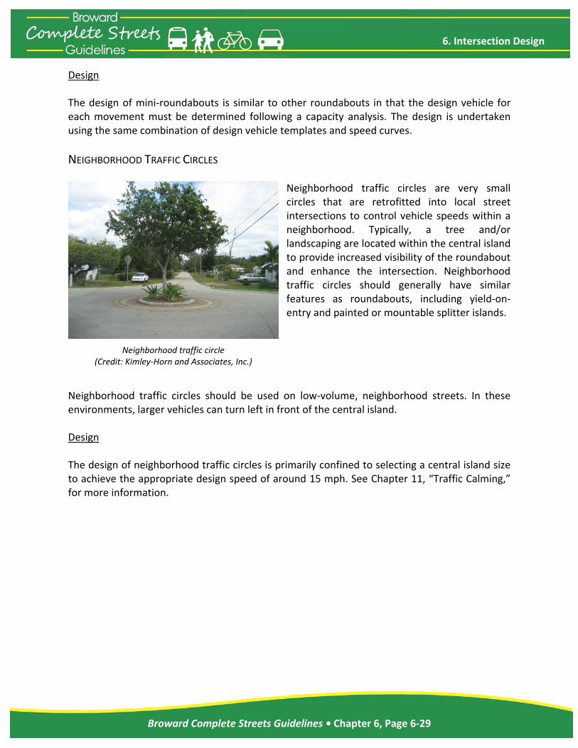
Neighborhood traffic circles are very small circles that are retrofitted into local street intersections to control vehicle speeds within a neighborhood. Typically, a tree and/or landscaping are located within the central island to provide increased visibility of the roundabout and enhance the intersection. Neighborhood traffic circles should generally have similar features as roundabouts, including yield‐on‐entry and painted or mountable splitter islands.
Neighborhood traffic circles should be used on low‐volume, neighborhood streets. In these environments, larger vehicles can turn left in front of the central island. Design The design of neighborhood traffic circles is primarily confined to selecting a central island size to achieve the appropriate design speed of around 15 mph. See Chapter 11, “Traffic Calming,” for more information.
Neighborhood traffic circle (Credit: Kimley‐Horn and Associates, Inc.)

6. Intersection Design
Broward Complete Streets Guidelines • Chapter 6, Page 6‐30
This page left blank intentionally.