CCU NanoGrid Configuration Manual (English) · CCU NanoGrid Configuration Manual (English)...
26
CCU NanoGrid Configuration Manual (English) Pd_CM_004. Version A.1 ChargeStorm AB March 16, 2018
Transcript of CCU NanoGrid Configuration Manual (English) · CCU NanoGrid Configuration Manual (English)...

CCU NanoGridConfiguration Manual
(English)Pd_CM_004. Version A.1
ChargeStorm AB
March 16, 2018

CCU NanoGridConfiguration Manual (English)
Contents1 Introduction 3
1.1 Connecting the CCU . . . . . . . . . . . . . . 31.2 Overview . . . . . . . . . . . . . . . . . . . . 5
2 License 7
3 NanoGrid™ 83.1 Server . . . . . . . . . . . . . . . . . . . . . . 83.2 Client . . . . . . . . . . . . . . . . . . . . . . 9
4 NanoGrid™ Configuration 104.1 Introduction . . . . . . . . . . . . . . . . . . . 104.2 Configuration . . . . . . . . . . . . . . . . . . 104.3 GCU/Master configuration - nanogrid.ini . . . 11
4.3.1 Contents . . . . . . . . . . . . . . . . 124.3.2 Fuse Format . . . . . . . . . . . . . . 134.3.3 Station format . . . . . . . . . . . . . 144.3.4 Installation . . . . . . . . . . . . . . . 15
4.4 NanoGrid node configuration - chargemanager.ini 164.4.1 FW prior to r3.6 . . . . . . . . . . . . . 16
4.5 Verification . . . . . . . . . . . . . . . . . . . 174.6 Complete Example . . . . . . . . . . . . . . . 174.7 Advanced Configuration . . . . . . . . . . . . 19
4.7.1 Scheduler . . . . . . . . . . . . . . . . 204.7.2 Phase-switching . . . . . . . . . . . . 204.7.3 Fallback configuration . . . . . . . . . 214.7.4 HCC units . . . . . . . . . . . . . . . . 234.7.5 Feedback from non-EVSE loads . . . 244.7.6 Aggregated feedback node . . . . . . 25
2

CCU NanoGridConfiguration Manual (English)
1 IntroductionThis document is a guide for service technicians to config-
ure a NanoGrid master station or GCU.For general information on how to configure the charging
station via the web based interface and how to upload con-figuration files, see the “CCUManual (English)”. Appropriatetechnical knowledge and certification for work with electri-cal installations and maintenance work is required to preventdanger to persons or property.
1.1 Connecting the CCUWindows machine to configure the CCU, and it is the firsttime you connect to the CCU, then please follow the providedinstruction to set up the driver correctly.
1. Power up the board.
2. Attach the mini-B USB connector to the CCU board,see Figure 1.1.
3. Open your preferred web browser and enter 192.168.7.2in the URL bar and press enter.
3

CCU NanoGridConfiguration Manual (English)
Figure 1.1: USB connector connected to the CCU.
4

CCU NanoGridConfiguration Manual (English)
1.2 OverviewThe first page after you connected to the system are the signin page. Some parts of the configurations interface are ex-plained below.
Figure 1.2: Sign in page.
1. Information box that shows some help text about everypage you navigate to. Click the box to expand the text.
2. The navigation menu, grayed out when your not signedin.
3. Click the flag to select the preferred language.
4. Input field to sign in. Username: ccu and password:ccu.
5

CCU NanoGridConfiguration Manual (English)
5. Connection status. Shows if the browser has a con-nection to the system. Green arrows indicates that thecontroller is connected. Flashing red arrow indicatesthat the browser trying to reconnect to the system.
We’ll only have a look at the license and NanoGrid pageshere. For the rest, have a look in the “CCU Manual (En-glish)”.
6

CCU NanoGridConfiguration Manual (English)
2 LicenseSome functionality on the station requires an appropriate
software license. Please contact your vendor for more in-formation. On this page you can upload a new license fileor download present file and see what the current licensecover.
Figure 2.1: License overview.
7

CCU NanoGridConfiguration Manual (English)
3 NanoGrid™3.1 ServerNanoGrid™ allows the charging station to adapt chargingto local grid conditions. For advanced configuration pleasecontact the manufacturer.On this page you can upload new NanoGrid configuration
or download current file.
Figure 3.1: Overview of NanoGrid server tab.
Uninterruptible Power Supply Detect if the site is runningon UPS battery power. Do not activate unless youknow what you are doing.
8

CCU NanoGridConfiguration Manual (English)
3.2 Client
Figure 3.2: Overview of NanoGrid client tab.
NGC Endpoint Endpoint to the NanoGrid controller. Leaveblank for auto-detection.
Outlet fallback current Current to assign the outlet in caseof lost NanoGrid communication.
Outlet fallback output Phase(s) to assign the outlet in caseof lost NanoGrid communication (only applicable forphase-shifting units).
9

CCU NanoGridConfiguration Manual (English)
4 NanoGrid™Configuration4.1 IntroductionNanoGrid is a load balancing solution for electrical vehicle(EV) charging. It will ensure that the available electrical ca-pacity is not exceeded by the connected NanoGrid EVSEunits.NanoGrid compliant EVSE units (e.g CCU R1.95+) are
required for a NanoGrid installation. Management of non-NanoGrid units in a NanoGrid scenario is out of scope forthis document.
4.2 ConfigurationIn order for NanoGrid to make correct decisions and actionstheNanoGrid installation needs to be configured for NanoGrid.The most important configuration is the configuration of
the local controller unit.The local controller unit comes in two variants:
• Grid Controller Unit (GCU) - A unit that is dedicated tothe task of load balancing. Typically placed in a sepa-rate cabinet.
• Master Controller Unit (Master) - A unit that is also actsas a charging station. The exterior is typically the sameas controlled charging stations.
The GCU offers more possible configurations of NanoGridas well as is able to manage more units. For example, the
10

CCU NanoGridConfiguration Manual (English)
GCU can manage a system with non-NanoGrid units sharingthe electrical capacity of the installation. For more advancedand optional configuration, please refer to the “Advanced”section.Documentation contained herein is applicable to both sce-
narios.Before the configuration of a NanoGrid installation please
ensure the following:
• NanoGrid compliant units are in use
• Units are equipped with appropriate licenses
• The local electrical grid conditions are known
• Electrical installation is finished andwill not shortly change
• Units contain a valid LAN configuration (non-LAN con-figuration is out of scope for this document)
• Appropriate firmware is in use. As of writing 3.5.7 orlater is recommended.
4.3 GCU/Master configuration -nanogrid.ini
The central piece of configuration in a NanoGrid installationis the NanoGrid configuration file placed on the local con-troller unit.This file defines how the nodes are connected electrically
as well as how they may be reached by the local controllerunit.
11

CCU NanoGridConfiguration Manual (English)
The configuration file is canonically named nanogrid.iniand is in a INI-file format (for more information about the INI-file format see: https://en.wikipedia.org/wiki/INI_file).Create (or edit an existing) nanogrid.ini with a text edi-
tor that understands and respects UNIX-style line-endings.WindowsNotepad is NOT acceptable. For an acceptable ed-itor available forWindows see: https://notepad-plus-plus.org/. Do NOT use symbols not covered by ASCII (e.g åäö).
4.3.1 ContentsThe file contains two things:
• General NanoGrid configuration
• Node configuration
General NanoGrid configuration is out of scope for thisdocument. General configuration include but is not limitedto configuration of the NanoGrid scheduler. Default optionsthat will be used in the absence of configuration will sufficefor the intended audience of this document.In scope for this document is two of the most common
node types:
Fuse A fuse, circuit breaker or earth breaker. The node cannot be controlled but imposes a limit on the amount ofavailable electrical capacity.
Station A NanoGrid compliant charging station. The nodecan be directly controlled by the local controller.
12
CCU NanoGridConfiguration Manual (English)
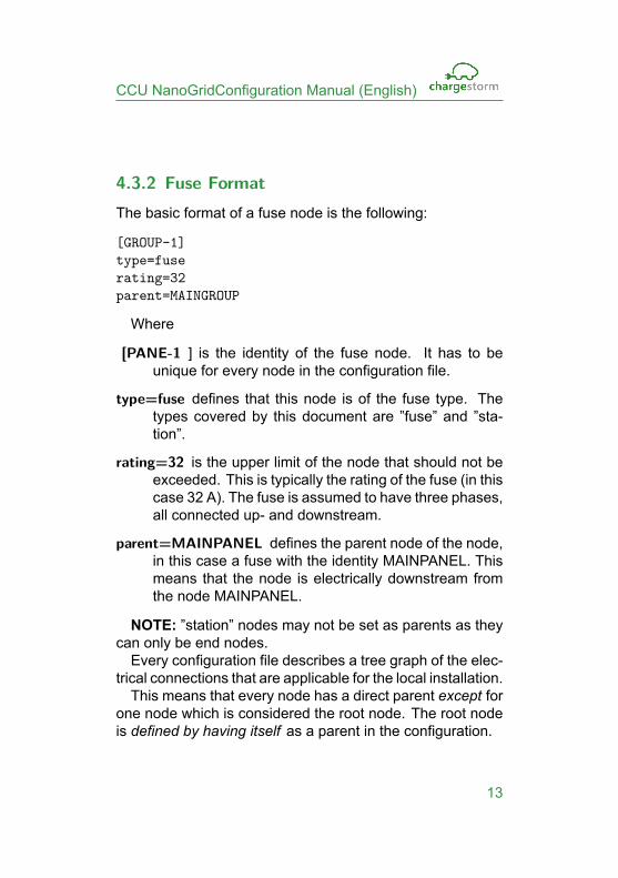
4.3.2 Fuse FormatThe basic format of a fuse node is the following:
[GROUP-1]type=fuserating=32parent=MAINGROUP
Where
[PANE-1 ] is the identity of the fuse node. It has to beunique for every node in the configuration file.
type=fuse defines that this node is of the fuse type. Thetypes covered by this document are ”fuse” and ”sta-tion”.
rating=32 is the upper limit of the node that should not beexceeded. This is typically the rating of the fuse (in thiscase 32 A). The fuse is assumed to have three phases,all connected up- and downstream.
parent=MAINPANEL defines the parent node of the node,in this case a fuse with the identity MAINPANEL. Thismeans that the node is electrically downstream fromthe node MAINPANEL.
NOTE: ”station” nodes may not be set as parents as theycan only be end nodes.Every configuration file describes a tree graph of the elec-
trical connections that are applicable for the local installation.This means that every node has a direct parent except for
one node which is considered the root node. The root nodeis defined by having itself as a parent in the configuration.
13

CCU NanoGridConfiguration Manual (English)
Example:
[MAINPANEL]type=fuserating=40parent=MAINPANEL
4.3.3 Station formatThe basic format of a station node is the following:
[NG-STATION-1]type=stationendpoint=mqttrating=16parent=MAINPANELoutlet/size=2outlet/1/connections=1,0,0outlet/2/connections=2,3,1
Where
[NG-STATION-1 ] is the identity of the station node. It hasto be unique for every node in the configuration file. Italso has to correspond with the chargeboxidentity pa-rameter set on the charging station.
type=station defines that this node is of the station type.The types covered by this document are ”fuse” and”station”.
endpoint=mqtt defines the endpoint of the NanoGrid sta-tion. The endpoint configuration in scope for this doc-ument is a mqtt endpoint. In this case the node will beaccessed via the local MQTT server.
14
CCU NanoGridConfiguration Manual (English)
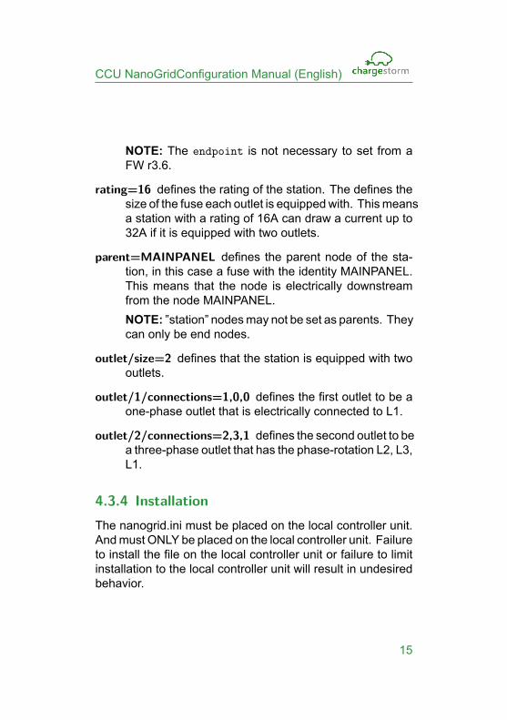
NOTE: The endpoint is not necessary to set from aFW r3.6.
rating=16 defines the rating of the station. The defines thesize of the fuse each outlet is equippedwith. Thismeansa station with a rating of 16A can draw a current up to32A if it is equipped with two outlets.
parent=MAINPANEL defines the parent node of the sta-tion, in this case a fuse with the identity MAINPANEL.This means that the node is electrically downstreamfrom the node MAINPANEL.NOTE: ”station” nodesmay not be set as parents. Theycan only be end nodes.
outlet/size=2 defines that the station is equipped with twooutlets.
outlet/1/connections=1,0,0 defines the first outlet to be aone-phase outlet that is electrically connected to L1.
outlet/2/connections=2,3,1 defines the second outlet to bea three-phase outlet that has the phase-rotation L2, L3,L1.
4.3.4 InstallationThe nanogrid.ini must be placed on the local controller unit.Andmust ONLY be placed on the local controller unit. Failureto install the file on the local controller unit or failure to limitinstallation to the local controller unit will result in undesiredbehavior.
15

CCU NanoGridConfiguration Manual (English)
The nanogrid.ini file may be uploaded via the stations webinterface. Select: ”CCUNanoGrid Configuration” and choosethe prepared file and click ”Upload NanoGrid configuration”.NOTE: If the nanogrid.ini file is malformed the firmware
will abort execution.
4.4 NanoGrid node configuration -chargemanager.ini
NOTE: NanoGrid node configuration has to take place onevery node that is to be managed by the local controller.The configuration needs to take place even on a master con-troller.Regular configuration of chargemanager.ini is out of scope
for this document. It is assumed to have been completedcorrectly.From the web interface ensure that ”Enable NanoGrid™
Load Balancing” is set to ”Yes”.
4.4.1 FW prior to r3.6Not necessary on r3.6 or later.Next a ”hidden” parameter need to be edited/added. This
parameter cannot be seen nor edited via the web interface.Download the chargemanager.ini configuration file from
the web interface with ”Retrieve the current ChargeManagerconfiguration”Edit the retrieved chargemanager.ini with a text editor that
understands and respects UNIX-style line-endings. Windows
16

CCU NanoGridConfiguration Manual (English)
Notepad is NOT acceptable. For an acceptable editor avail-able for Windows see: https://notepad-plus-plus.org/ . DoNOT use symbols not covered by ASCII (e.g åäö).Once open, the file needs the parameter gcuendpoint un-
der [General] category in the file. The endpoint should bemqtt://[IP]. Where [IP] is the IP address of the localcontroller.Example:
[General]...gcuendpoint=mqtt://192.168.1.1...
Once the parameter is set, save the file and upload it tothe station being configured.
4.5 VerificationOnce the local controller and all NanoGrid stations have beenconfigured, it is time to verify the installation.Should a station fail to start a charge, faulty configuration
or network issues may be suspected.Should the electrical grid have been incorrectly described
this will either result in sub-optimal performance or a risk oftripping fuses.
4.6 Complete ExampleBelow is a complete example of a configuration file. Theconfiguration starts with a 63 A main fuse with two 35 A sub-
17

CCU NanoGridConfiguration Manual (English)
fuses. On each 35 A sub-fuse two 16 A single phase stationsare connected.
[MAINPANEL]type=fuserating=63parent=MAINPANEL
[GROUP-1]type=fuserating=35parent=MAINPANEL
[GROUP-2]type=fuserating=35parent=MAINPANEL
[STATION1]type=stationendpoint=mqttrating=16parent=GROUP-1outlet/size=2outlet/1/connections=1,0,0outlet/2/connections=2,0,0
[STATION2]type=stationendpoint=mqttrating=16parent=GROUP-1
18

CCU NanoGridConfiguration Manual (English)
outlet/size=2outlet/1/connections=3,0,0outlet/2/connections=1,0,0
[STATION3]type=stationendpoint=mqttrating=16parent=GROUP-2outlet/size=2outlet/1/connections=2,0,0outlet/2/connections=3,0,0
[STATION4]type=stationendpoint=mqttrating=16parent=GROUP-2outlet/size=2outlet/1/connections=1,0,0outlet/2/connections=2,0,0
4.7 Advanced ConfigurationFor some scenarios more advanced NanoGrid™ configura-tion is required.
19

CCU NanoGridConfiguration Manual (English)
4.7.1 SchedulerThe scheduler controls how scheduling will take place. Asof writing three schedulers exist.
• Equal - Attempts to maintain a “fair” distribution
• Fifo - First in first out scheduling
• French - A feedback based scheduler
The first two schedulers are designed for open-loopNanoGrid™scenarios. If the site is equipped with working energy metersthe “French” scheduler should be prefered.The scheduler is controlled by setting the “scheduler” pa-
rameter at the top-level category “[General]”.
Example
[General]scheduler=FIFO
...
4.7.2 Phase-switchingIf a station is phase-switching it has the capability to eitherprovide three-phase current or a single phase which it canchoose as appropriate.An outlet is configured as phase-switching by setting the
connections to the word “switch”.NOTE:As of writing not all schedulers support phase-switching.
Only the FIFO scheduler and FRENCH scheduler are sup-ported.
20

CCU NanoGridConfiguration Manual (English)
Example
...
[SWITCHING-A]type=stationendpoint="mqtt"rating=16parent=MAINPANELoutlet/size=2outlet/1/connections="switch"outlet/2/connections="switch"
...
4.7.3 Fallback configurationIn the event that a managed node loses contact with a localcontroller it will not be able to charge any EV unless a fallbackconfiguration has been specified.The fallback configuration consists of one or two parame-
ters depending on the type of node.For non-phase switching nodes only a fallback current is
required while phase switching nodes requires a fallback out-put as well.NOTE: As of writing it is up to the person configuring the
system to ensure that the combined fallback currents do notassign too much in the event of a local controller failure.The fallback current is an integer which by default is as-
sumed to be 0 i.e no allowed current when in fallback mode.The value is in amperes, e.g setting the parameter to 16 will
21

CCU NanoGridConfiguration Manual (English)
tell the local controller to reserve 16 A and the station to pro-vide 16 A when communication is lost.The fallback output tells a phase switching station onwhich
output should be provided when offline. The value has thefollowing possible values:
• 0 - No output
• 1 - Three phase output
• 2 - Single phase L1
• 3 - Single phase L2
• 4 - Single phase L3
Example
...
[STATIC-1]type=stationendpoint="mqtt"rating=16parent=MAINPANELoutlet/size=2outlet/1/connections=1,0,0outlet/1/fallback_current=8outlet/2/connections=2,0,0outlet/2/fallback_current=8
[SWITCHING-A]type=station
22

CCU NanoGridConfiguration Manual (English)
endpoint="mqtt"rating=16parent=MAINPANELoutlet/size=2outlet/1/connections="switch"outlet/2/connections="switch"outlet/1/fallback_current=8outlet/1/fallback_output=2outlet/2/fallback_current=8outlet/2/fallback_output=3
...
4.7.4 HCC unitsAHCCunit with proper firmwaremight be present in a NanoGrid™scenario. To add HCC unit to the “hcc” node type needs tobe specified. In addition a path to the HCC unit and its asso-ciated energy meter is required. The meter might be omittedif only open-loop scheduling is required.The specification of the HCC and meter path takes the fol-
lowing form: “modbus/X/Y” where X is the RS485 channel onthe local controller logic board and Y is the assigned modbusslave address.NOTE:While the configuration of the HCC itself is outside
the scope of this document the HCC requires correct manualconfiguration in order to participate in the NanoGrid™ sce-nario.
23

CCU NanoGridConfiguration Manual (English)
Example
...
[HCC-1]type=hccendpoint="modbus/1/1"meter="modbus/1/2"rating=16parent=MAINPANELoutlet/size=2outlet/1/connections=1,0,0outlet/2/connections=2,0,0
...
4.7.5 Feedback from non-EVSE loadsIf a node has an external load that is measured the schedulercan take it into consideration. For example assume that afuse both have a charging station and large fan attached.Then if the load of the fan is measured the scheduler cantake it into account.
Example
...
[SHARED-FUSE]type=measuredfusemeter="modbus/1/1"rating=20
24

CCU NanoGridConfiguration Manual (English)
parent=MAINPANEL
[STATION-1]type=stationendpoint="mqtt"rating=16parent=SHARED_FUSEoutlet/size=2outlet/1/connections=1,0,0outlet/2/connections=2,0,0
...
4.7.6 Aggregated feedback nodeIf a node has an energy meter attached that measures theload at that point, i.e the aggregated load of the sub nodesthe scheduler may use that information to make its schedul-ing.This is in contrast to the measured fuse where only the
external load is measured. In essence the aggregated fuseis the sum of non-EV loads and EV loads.
Example
...
[AGGREGATED-FUSE]type=aggregatedfusemeter="modbus/1/1"rating=20
25

CCU NanoGridConfiguration Manual (English)
parent=MAINPANEL`
[STATION-1]type=stationendpoint="mqtt"rating=16parent=SHARED_FUSEoutlet/size=2outlet/1/connections=1,0,0outlet/2/connections=2,0,0
...
26