Capstone project CIVI 490
125
4/2/2013 Rehabilitation of the Grey Nuns Building Complex CAPSTONE CIVIL ENGINEERING DESIGN PROJECT 2012-2013 TEAM 8 PRESENTED TO: DR. A. M. HANNA
description
CIVI 490 capstone project 2013
Transcript of Capstone project CIVI 490

4/2/2013 Rehabilitation of
the Grey Nuns Building Complex CAPSTONE CIVIL ENGINEERING
DESIGN PROJECT 2012-2013
TEAM 8 PRESENTED TO: DR. A. M. HANNA
1 | P a g e
Contents
1.0 TEAM MEMBERS AND TASK DISTRIBUTION................................................................. 4
2.0 INTRODUCTION .................................................................................................................... 5
2.1 Site Visits and Plan Obtainment............................................................................................ 6
2.2 Building Condition Prior To Modernization ......................................................................... 6
2.3 Concordia University’s Contribution .................................................................................... 8
3.0 REMODELING & FEATURES OF THE GN BUILDING ..................................................... 9
3.1 Structural Features................................................................................................................. 9
3.1.1 Columns .......................................................................................................................... 9
3.1.2 Floor slab ...................................................................................................................... 11
3.1.3 Steel Deck ..................................................................................................................... 11
3.2 Architectural Features ......................................................................................................... 14
3.2.1 Interior walls ................................................................................................................. 14
3.2.2 Parking .......................................................................................................................... 15
3.2.3 Features ......................................................................................................................... 15
4.0 GLASS DOME ....................................................................................................................... 16
4.1 Steel Framework & Glazing Design ................................................................................... 19
4.2 Improvements ...................................................................................................................... 21
4.3 Load Calculations ................................................................................................................ 22
4.4 Foundation Design .............................................................................................................. 23
4.5 Structural Analysis of the Dome ......................................................................................... 23
4.5.1 Structural components ............................................................................................ 24
4.6 Slab & Column Design ....................................................................................................... 26
4.7 Stairs Design ....................................................................................................................... 27

2 | P a g e
4.8 Environmentally Sustainable Design .................................................................................. 28
4.8.1 Solar Energy ................................................................................................................. 28
4.8.2 Rainwater Collection & Recycling System ................................................................... 29
5.0 TUNNEL................................................................................................................................. 45
5.1 Introduction ......................................................................................................................... 45
5.2 Geotechnical Report ............................................................................................................ 46
5.3 Load Calculations ................................................................................................................ 46
5.4 Tunnel Properties and Assumptions .................................................................................... 47
5.5 Alternative Tunnel Design .................................................................................................. 48
6.0 COMPREHENSIVE COST ANALYSIS ............................................................................... 49
6.1 WinEstimator Software ....................................................................................................... 49
6.2 Subcontractor Price Quotations ........................................................................................... 51
6.3 Total Estimated Cost Analysis ............................................................................................ 51
7.0 CONSTRUCTION PROCESSES: TUNNEL......................................................................... 53
7.1 Excavation ........................................................................................................................... 53
7.2 Precast Concrete Placement ................................................................................................ 54
7.3 Paving & Finishing ............................................................................................................. 54
8.0 CONSTRUCTION PROCESSES: GN BUILDING .............................................................. 56
8.1 Demolition of the Kitchen Building .................................................................................... 56
8.2 Demolition and Replacement of Structural Components .................................................... 56
8.3 Interior Finishing & Landscaping ....................................................................................... 57
9.0 CONSTRUCTION PROCESSES: DOME ............................................................................. 58
9.1 Destruction of Existing Building......................................................................................... 58
9.2 Handling of debris ............................................................................................................... 58
9.3 Erection of the Dome Structure ........................................................................................... 58

3 | P a g e
10.0 GANTT CHART FOR WORK SCHEDULE....................................................................... 59
Appendix ......................................................................................................................................... 0
1.0 STEEL DECK DIAPHRAGM DESIGN .................................................................................. 1
1.1 Earthquake Load ................................................................................................................ 1
1.2 Design of steel deck ........................................................................................................... 3
1.3 Check deflection of the selected roof steel deck ............................................................... 3
2.0 TUNNEL SAP2000 ANALYSIS ........................................................................................ 5
2.1 Concrete Frame ..................................................................................................................... 5
2.2 Bending Moment Diagram of Concrete Tunnel Frame ................................................... 5
2.3 Shear Force Diagram of Concrete Tunnel Frame ............................................................ 6
3.0 DOME SLAB ETABS ANALYSIS FOR REINFORCEMENT .............................................. 7
4.0 DOME: COLUMN REINFORCEMENT ............................................................................... 11
5.0 DOME STAIRS DESIGN ...................................................................................................... 13
Design procedure for flight of stairs ...................................................................................... 13
5.1 Design of Stair Slab ......................................................................................................... 14
6.0 RAINWATER COLLECTION SYSTEM .............................................................................. 18
7.0 COMPLETE QUANTITY TAKE-OFF ................................................................................... 0

4 | P a g e
1.0 TEAM MEMBERS AND TASK DISTRIBUTION
NAME I.D. SPECIALIZATION TASK DESCRIPTION
Kethayini
Kanthasamy 9607285 Infrastructure
AutoCAD
Surveying
Base Plate Design
Tunnel Design
Maryia Koneva 9575340
CEM
(Construction
Management)
Surveying
Project Management & Scheduling
Cost Estimation
Karl Lai 9579303 Infrastructure
Dome Structural Design
GN Remodelling Design
Surveying
Dome SAP2000 Modeling
Steel & Concrete Structural Design
AutoCAD Drafting
Basma Salame 9652620 Environmental
Dome Layout/Design AutoCAD
Environmentally Safe Design Standards
(LEED)
Rainwater Recycling System
Surveying
Jordano Serio 9580484
CEM
(Construction
Management)
Material Quantity & Cost Estimation
Subcontractor Contact & Co-ordination
Construction & Project Management
Surveying
Sara Syed 9279822 Infrastructure
AutoCAD
Surveying
GN Column Design
SAP 2000 Tunnel Modeling
Tunnel Design
Smail Taghzout 6013511 Infrastructure
AutoCAD Drafting
Structural Analysis & Design
ETABS Modelling GN
Surveying
Table 1

5 | P a g e
2.0 INTRODUCTION
The project entails the renovation and redesign of a section of the Grey Nun’s Building
(GN building) in order to progress and develop its use for both Faculty members and students of
Concordia University. The remodeling aspect consists primarily of structurally and architecturally
modernizing a section of the F-wing inside the GN Building for Concordia headquarters, which
includes the office of the President, Vice-Presidents, Administrative Staff, Facilities Management,
and accompanying staff for the above-mentioned members. In addition, a solar geodesic dome
designed entirely by the team is proposed as a replacement of the cafeteria building located at the
heart of the Grey Nuns domicile. The dome is constructed mainly of steel and glass, and serves as
a green area for Concordia University as well as a cafeteria and sitting quarter. Concordia
University headquarters are currently situated inside rented duplexes by the Finance Department
along the downtown campus, and therefore having a general unit specifically intended for the
university’s headquarters is proposed as a solution. The GN Building has not been inaugurated
with a specific function for the university as of yet; the building’s aesthetically pleasing structure
as well as its’ historical and religious design detailing is a pride for Concordia University, and
therefore using this building will provide a practical, elegant, yet modern headquarter complex for
the university.
Since the central cafeteria building is excluded as a historical component, the complete demolition
and rebuilding can be easily accomplished for the dome structure. A supplementary structural
element for the proposed design is a connecting tunnel from the GN building to the Toronto
Dominion Bank Building of Concordia University. As a result, all students, faculty, and staff will
have easy access from Guy-Concordia Metro, and a main floor parking lot will provide access to
the GN building. .

6 | P a g e
2.1 Site Visits and Plan Obtainment
Prior to designing, an important task was to coordinate with the facilities management
department of the university in order to obtain the official layouts and plans of the GN building.
Comprehensive measures from the entire team were taken to regularly meet with the Capstone lead
professor, Dr. Hanna, as well as with Mr. Jacques Lachance, Mrs. Martine Lehoux, and Mrs. Dorice
Desbiens. Some difficulties arose throughout the plan obtainment, since the team was dealing with
official documents and AutoCAD plans that belong to the university. A three-week delay resulted
from the initial approval to have access to the plans. An agreement was signed by all team members
and authorized by Dr. Hanna for confidentiality requirements, and was sent to the security
department of the Hall Building.
2.2 Building Condition Prior To Modernization
A site investigation was conducted at the GN building on Guy Street to evaluate the current
state of the structure. Only the basement and the ground floor were visited, due to privacy and
security, access were not permitted to the upper floors where the nuns currently reside.
First, the ground floor was surveyed visually
to make an educated assessment of the overall
condition of the building. The visible materials of
the existing structure on the ground and basement
level were a mix of concrete and wood. The
existing slabs at the ground floor level are made
of wood dating back to the 1870s as shown in
Figure 1. They are in a good condition but are not
suitable for the change in load that a modernization will bring to the GN building. The state of
some structural components such as columns, shear walls and bracing were not observed because
they were not visible. Also, the restricted accessibility to most the rooms prevented a thorough
investigation of the components mentioned above. Next, the basement was visited where a low
ceiling of 5’5” exposed the current concrete walls, columns and beams as shown in Figure 2. The
basement was unoccupied except for the use mechanical rooms.
Figure 1 Overview of the wooden slab

7 | P a g e
Figure 2 – Overview of the basement showing concrete components
Due to the historical value of the building, exterior changes to the façade are not permissible. This
applies to windows and the roof as well.
Thanks to the assistance of Concordia University’s architectural technician, Stephanie
Bradley, images of the upper
floors and of the roof have been
provided for further insight of the
structural integrity. The upper
floors appears to be built of
concrete and wood components
and are well preserved. On the
other hand, the roof is completely
made of wood as shown in Figure
3. It is in a deteriorating state
probably due to temperature
change throughout the seasons.
Figure 3 Roof structure of the GN building

8 | P a g e
The overall state of the building is in an acceptable condition. However, since the building was
constructed in 1870s, it does not conform to the updated national building code of Canada. In order
to modernize the building, a retrofit of the structural components of the GN building would be
necessary. Furthermore, the occupancy will change from residential to office areas, which will
require a change of the structural components to withstand the new loads.
2.3 Concordia University’s Contribution
The university’s Engineering and Computer Science faculty members and staff greatly
contributed to the accomplishment of this project. Several supervisors alongside our Capstone
Instructor, Dr. Hanna, guidance into the right ways of designing and gave us useful ideas and
modifications to simplify the structural design process. Dr. Galal, our supervisor, along with Dr.
El-Sokkary, Dr. Tirca, Dr. Willis, Dr.Han, and Dr. Mulligan assisted with practical and
constructive guidelines for the design and project completion.
Furthermore, it was fortunate for the team to have access to the university’s surveying
equipment, through a written request to Mr. Lachance, who helped the team obtain all necessary
equipment in order to survey both the indoor and outdoor domicile of the GN Building. The
surveying of the basement, first, and second floor of the F-Wing of the GN were accomplished, as
well as the garage, outdoor circumference, parking lot, and building elevation. In addition, the
team attended a guided tour by the Grey Nuns recreational administration, where a thorough visit
to the building’s historical landmarks and rooms was done.

9 | P a g e
3.0 REMODELING & FEATURES OF THE GN BUILDING
The east wing of the Grey nun’s residence will be undertaking some major renovations, it is
important to note that
the outside layer of the
structure is not to be
touched or damaged
because of its historical
importance. Therefore,
the indoor structures of
the building will all be
remodeled and updated
with some of the latest
features in the
construction industry.
The demolition process
of the structure will
require a lot of
planning and will need to be conducted in several steps.
3.1 Structural Features
3.1.1 Columns
The columns of the building are currently in Concrete. Although they seem to still be in a fair
condition, an analysis will be required in order to determine fully their current condition. The edge
and corner columns will not be replaced, since they are part of the external structure of the building.
A reinforcement of these columns might be necessary, but a coring sample would be necessary so
that the concrete column will be subjected to the necessary test. As for the interior columns, they
will be replaced by steel columns of different sizes. A detailed calculation of column design can
be found in the annexe of this report. Every column will be seated on a base plate for its respective
dimension. The base plate will help on increasing the torsional resistance of the column as well as
its resistance toward buckling.
Figure 4 Existing condition of the structure
10 | P a g e
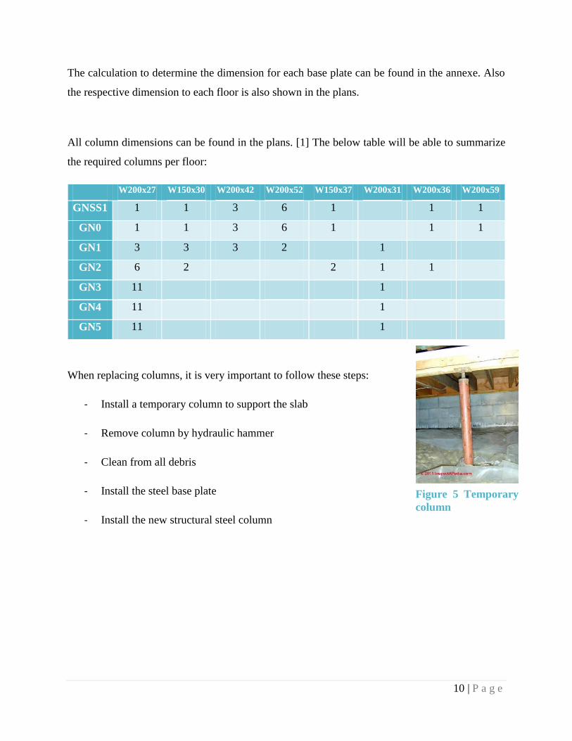
The calculation to determine the dimension for each base plate can be found in the annexe. Also
the respective dimension to each floor is also shown in the plans.
All column dimensions can be found in the plans. [1] The below table will be able to summarize
the required columns per floor:
W200x27 W150x30 W200x42 W200x52 W150x37 W200x31 W200x36 W200x59
GNSS1 1 1 3 6 1 1 1
GN0 1 1 3 6 1 1 1
GN1 3 3 3 2 1
GN2 6 2 2 1 1
GN3 11 1
GN4 11 1
GN5 11 1
When replacing columns, it is very important to follow these steps:
- Install a temporary column to support the slab
- Remove column by hydraulic hammer
- Clean from all debris
- Install the steel base plate
- Install the new structural steel column
Figure 5 Temporary
column

11 | P a g e
3.1.2 Floor slab
The existing floor system is mainly consisting of a series of wood beams which are supported by
concrete columns. The
secondary beams are also
composed of wood. Its
condition seems to continue
holding the structure firmly but
some deterioration is occurring
on the secondary beams. It can
be caused by moisture, humidity
or simply by aging. To be able
to accommodate the new weight
on the structure, the slab will
need to be fully replaced.
Before undertaking any
demolition, it will be important to install a temporary structure before removing any pieces
pertaining to the floors, this will help in supporting any temporary live weight but also facilitate
the demolition process.
3.1.3 Steel Deck
The wood slab in this structure will be replaced by a steel deck. Selecting a proper steel deck is
dependant not only of gravitational loads, but also lateral loads. For the location of our structure,
the dominating lateral load is the Earthquake load, which was found to be 297.31 kN at its highest
value, which is the top floor of the structure. Following the CANAM standards, the proper steel
deck to use would be the P-3606. [2]Once installed, the horizontal brace is used as a diaphragm.
The design requirement for a steel deck are as follow:
- The deck profile and thickness;
- The spacing and the type of connectors at support;
- The spacing and the type of connectors at side-lap;
- The span of the deck.
Figure 6 Initial column and slab condition

12 | P a g e
Figure 7 Steel Deck Design
13 | P a g e
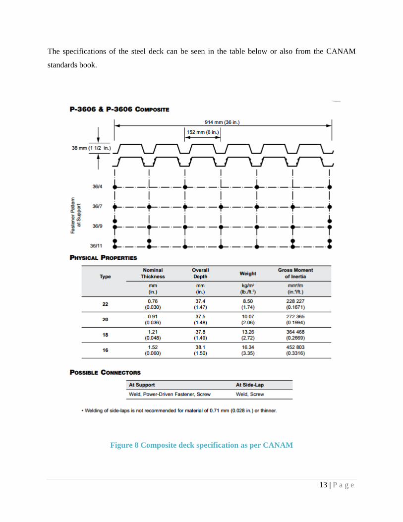
The specifications of the steel deck can be seen in the table below or also from the CANAM
standards book.
Figure 8 Composite deck specification as per CANAM

14 | P a g e
3.2 Architectural Features
3.2.1 Interior walls
The initial condition of the indoor wall is mainly
composed of gypsum sheets. And contain no structural
value. The walls serve only as a separation wall. These
interior walls will be replaced by a modern interior glass
curtain wall. These interior wall will still serve no
structural values to the building and will only add some
dead weight to the structure. The purpose of using these
type of walls are not only for a better esthetic but also they
permit better light transmittance and better natural heat
distribution. The thickness of the glass and its thermal property is what determine the heat loss
property of the wall. Other interior wall will follow standard construction. A rigid frame
withholding gypsum sheets. The location of every wall is well details in the layout plans of the
structure.
Figure 9 Interior of the grey nuns residence
Figure 10 Interior curtain wall sample

15 | P a g e
3.2.2 Parking
The parking is located on the North West side of the F-wing
of the structure. It is a 2 story structure where the upper floor
is used as storage. To optimize the spacing for parking, only
a new parking markings will be needed. On the upper floor,
it will be used as a resting area for the maintenance staff.
Therefore there is no particular demolition to be followed.
Only aesthetic adjustment will be required. The layout of this
new structure can be seen in the plan.
3.2.3 Features
The remodeling of the GN building will permit the installation of many new features, many will
be explained in details further in the report. Some of the features include, a recycling water system,
an acoustics amphitheatre and high ceilings. The floor finish will be a mixture of carpentry and
acrylic. Standard industrial and office lightning will be used. As per doors, office doors will be
standard wood doors with frost tempered glass. Revolving glass doors will also be used in the main
entrance lobby. The windows will not be touched since it may damage the exterior structure.
Window cocking will be replaced to reduce any heat dissipation.
Figure 12 Sample office layout rendering
Figure 11 Initial parking condition

16 | P a g e
4.0 GLASS DOME
An important addition to the design and renovation of the Grey Nuns building is the
construction of a glass dome. This 653 m2, 10 m high glass structure is composed of a steel
framework and glazing surface. The function of this structural component serves several purposes:
Provides the Concordia University downtown campus with an open green area for
leisure, eating, and meeting purposes for Faculty, staff members, and visitors
Presents an energy-efficient headquarter for Concordia University, satisfying
numerous LEED requirements
Demonstrates a unique and aesthetically-pleasing steel structural design in the
center of downtown for officials and university heads to benefit
Exhibits a semi-circular and cylindrical shape, which altogether provide strength,
durability, and flexibility
Figure 13 Dome Architectural Layout (AutoCAD)

17 | P a g e
As shown in the figure, the layout includes a one story open hall divided into two different
compartments. The main lobby at the entrance includes a reception desk for guests and visitors
where the office of the receptionist and administrators will be situated. The semi-dome will
originate at 28 m of the rectangular layout and extend towards a 9.25 diameter. This semi-circular
location will serve as an indoor garden, with a large seating area. As shown in the figure, the
architectural layout illustrates the green area with interior-grown grass and trees.
Figure 14: Indoor Garden Design for Dome [3]
The heavily constructed concrete buildings occupying the downtown area of Montreal are
reducing the amount of green space available. Being a central area for key economic, political, and
social vicinities, the lack of natural “green” landmarks are understandable. A proposed solution is
to allow Concordia University’s downtown campus to encompass a green space for professional
services contributing to the Concordia community. While the GN building’s renovation will
comprise of designing new offices for the university officials, the glass dome will be a central
leisure location, with a kitchen in the basement, serving all those individuals who reside in the
surrounding Grey Nuns area during work hours.

18 | P a g e
There is an existing building and basement at the location where the dome will be built.
The basement currently serves as a kitchen to supply food to the GN building’s cafeteria. It is
furnished with kitchen equipment as shown in the picture below. It is intended that the kitchen is
to be renovated and re-used for preparing and providing food at the buffet in the main lobby area.
Doing so will reduce the cost for refurnishing the new kitchen.
Figure 15 Picture of existing kitchen provided by Concordia University

19 | P a g e
4.1 Steel Framework & Glazing Design
The final design for the dome’s structural composition was based on several alternative
steel truss combinations. Using SAP2000 as the main load and design analysis, two alternative
designs were made.
Figure 16: Alternative Design 1 Trapezoidal Truss System [4]
For this specific design, the truss system chosen
is composed of trapezoids of differing base
lengths and heights. This design, although less
structurally stable than the triangular orientation,
since it is not exclusively rectangular-shaped, it
still contains side slopes which strengthen the
truss system. Due to the side slopes, the truss is
stronger and is able to withstand wind and
seismic loads. The trapezoidal structure also
exhibits more glass surface area, allowing
“window” like glazing all across the dome.
The most structurally stable shape is that of the
triangle. The three-sided sloped figure is able to
withstand loads more effectively than all other
shapes. This type of dome is referred to as
geodesic domes, where the steel structure
encompasses triangles throughout the entire
surface area. The structurally rigid shape
distributes the point load very effectively, since
as the loads reach the vertex and sides, the forces
are evenly distributed. The tension and
compression forces balance efficiently compared
to rectangular, spherical, and trapezoidal cross-
sectional areas.
Figure 17 Alternative Design 2 Triangular Truss
System [24]

20 | P a g e
Spherical dome shapes in general perform well structurally, especially when the
construction material is composed of steel. Bracing increases structural stability, regardless of the
shape used. For the dome, the first design alternative was chosen, with the trapezoidal truss cross-
section. Although less stable compared to the triangular trusses, the trapezoidal shape allows larger
surface area for glazing, and conveniently fits with the dome’s cylindrical shape. Using triangles
will also conflict with the longitudinal steel framework needed to connect the rectangular section
of the dome. If the entire building was designed as a full sphere, the triangular shape would have
been suitable; however, the rectangular extension requires immediate connections from the semi-
sphere which become flat on the other side of the dome. Having triangular sections will complicate
the steel framework, since the cylindrical shape becomes flat at the other end of the building.
Referring to Figure 18, the dome shown displays two semi-spherical domes connected between a
portions of a cylinder of the same radius. The dome designed at the center of the Grey Nuns
building will have a flat edge instead of a semi-spherical shape at the end; this reasoning is merely
aesthetic, since the purpose of this edifice is professional rather than sport or recreational. As
shown in Figure 19, the dome model was designed using the software SAP2000. The steel
framework is illustrated with 5 strut layers, of respective angle measurements.
Figure 18 Alternative Edge Design of Dome [24]

21 | P a g e
Figure 19 Preliminary Design Figure 20 Final Design with Braces
As a result, the final design for the dome structure is a combination of a cylindrical vault
and a half sphere made of HSS steel tube members as shown in the following figures taken from
SAP2000. The main changes added to the preliminary design have been the addition of bracing
members to achieve the geodesic’s triangular shape connections to provide a higher stability to the
structure. By doing so, the dome’s shell increased from a two way grid to a four way grid design
which provides a better structural rigidity.
4.2 Improvements
There are spaces for improvements in the current dome design. The whole shell consists a
single layer grid and could have been greatly reinforced if it was a double layer grid. A double
layer grid would resist to lateral loads in all direction and would be more rigid. This alternative
would require more HSS member which is undesirable. Considering that the dome will be covered
in all three interior faces of the GN building, it is assumed that the dome will be exposed to less
lateral load and therefore does not require a double layer grid design.

22 | P a g e
4.3 Load Calculations
The loads taken into account for the design of the dome are the snow, dead, wind and
seismic loads. They are calculated based on NBCC 2010 which provides values and guidelines in
determining the estimated load that would be applied on the dome for analysis. All load
calculations are attached to the design brief at the end of the report.
The snow loads have been calculated considering the slope on the sides of the dome. Taking
into account the slope angles, it is assumed that snow or rain will slide off the roof through gravity
pull and melt on contact with the glass. Due to the change in angles, the snow load on each member
will decrease gradually from the top to the bottom member as instructed in the NBCC 2010. A
thickness of 5mm of ice has been considered for the case of extreme cold weathers which would
add an approximated value of 0.045 kPa to the snow load.
The dead loads considered in the design of the dome are the self-weight of the hollow steel
members and the self-weight of the glass. The choice of steel hollow members is for aesthetical
purposes and also contributes to an overall light weight of the structure. Also, hollow steel
members are more flexible and can be bent more easily than W section members.
The wind lateral load applied on the dome is calculated based on the NBCC 2010 static
method for building of less than 20 m in height. The lateral force applied on the dome is projected
so that the force is perpendicular at the dome’s glass or HSS member which resulted into different
lateral wind pressures at each level.
The seismic load is calculated using the NBCC 2010 assuming that the soil is class C in
reference to the geotechnical report used for the design of the tunnel. The values for Rd and Ro
taken in the code are 3.0 and 1.0 respectively assuming that the dome’s structure is moderately
ductile concentrically braced frame. Since the height of the dome is only 10m and it is surrounded
by the interior faces of the GN building, we also assumed that seismic load governs over wind load
which was later confirmed by the hand calculations of the lateral loads.

23 | P a g e
4.4 Foundation Design
There is an existing foundation under the building where the dome will be built.
Considering that the dome is composed of steel hollow members, it is assumed that the weight of
the new dome would be a very light weighted structure which can possibly be lighter than the
existing building. Without knowing the current foundation layout, type and design information, it
was suggested by Dr. A. Hanna, Foundation professor at Concordia University, that the existing
foundation can be reused for the new dome. The current basement is used as a kitchen for providing
food to the Grey Nuns’ building. As the new dome will mainly serve as a sitting and eating area,
it is proposed to use the basement as a kitchen as well to provide food to the ground floor which
will be mainly a buffet area. However, the column layout will be changed and redesigned to
support the weight of the slab at the ground floor level.
4.5 Structural Analysis of the Dome
The analysis of the dome with respect to the gravity (see Figure 21) and lateral loads (see
Figure 22) has been done using SAP 2000. The model was assembled using the existing cylindrical
vault and sphere templates for which we determined the common height and the total length which
were then merged together. Thereafter, the gravity loads and seismic lateral were assigned and the
analysis was done on the model made up of HSS members. The results shows that the dome is
structurally sound when using HSS 219X10 for the horizontal members and HSS 60X3 for the
vertical and bracing members.
Figure 21 Dome analysis under gravity loads

24 | P a g e
Figure 22 Dome analysis under seismic load
4.5.1 Structural components
4.5.1.1 Steel members
The dome structure will be entirely made up of HSS steel members for aesthetical reasons
and also because the self-weight of the member is lighter than other steel members. Due to its light
weight, the HSS members are an advantageous choice of material because they are more
economical. Other advantages of HSS steel members include their strength to weight ratio, their
ease of fabrication, they are easily bent compared to W-section members and they can be recycled
for other purposes.
4.5.1.2 Bracing
Bracings have been added to the preliminary design of the dome in order to achieve
triangular shapes knowing that triangles are the most stable shapes due to their fixed angles which
will increase the durability and stability of dome.
4.5.1.3 Connections
The HSS tube members need to be connected at each joint and they can be done through
bolting or welding. However, it is not always convenient due to the angle created by the sloped
members of the dome. As a result, extruded aluminum nodes along with triodetic connections have
been chosen to connect the HSS members because they are specifically designed for this type of

25 | P a g e
connections. There is no calculation design required for this type of nodes because they are
manufactured and are chosen based on the axial forces exerted on them by the steel members.
Figure 23 Triodetic Node and Connection [5]

26 | P a g e
4.6 Slab & Column Design
The slab has a thickness of 245 mm and is made of reinforced concrete. The slab design
has been separated into two parts due to the different loads that are being applied on the slab. The
ground floor has been separated into two categories: the assembly area and the sitting area. The
assembly area has a live load of 4.8 kPa which has been determined from the NBCC 2010. Whereas
the sitting area will include grass, trees and soil which explains the need of considering a 10 kPa
live load.
In order to support the weight of the new slab with variable live loads, new columns have
been designed in respect to the new loading. However, the dimensions of the new columns
supporting the slab at the basement level will not be uniform for the interior, edge and corner
columns. The new dimensions are listed in the table below:
Interior Corner Edge
Assembly area 400x400 mm 200x200 mm 450x450 mm
Sitting area 800x800 mm 300x300 mm 850x850 mm
Table 2 New Columns Dimensions
Figure 24 Assembly area NS (Bottom reinforcement)

27 | P a g e
4.7 Stairs Design
The stairs have been designed in concrete inside the dome, since the entire slab and
columns of the dome, leading to the basement, are in concrete. The design procedure involves
calculating dead and live loads and separating these into stairs slab and flight section of stairs.
According to the National Building Code of Canada, for stair design regulations, a rise of 200 mm
following a run of 250 mm was chosen as a suitable combination for the service type stairs of
height of 3.60 m, with a railing of 0.8 m or 800 mm. The slab design length was determined to be
1.495 m, 0.245 m thick (245 mm slab thickness). The dome staircase will originate in the basement
and lead to the ground floor upstairs, in a simple two-way staircase design. The width of each
staircase is 1.25 m, with a total 2.50 m for both sides longitudinally.
The stairs will be supported by the foundation columns and beams, designed in concrete.
The slab thickness, as mentioned previously, has a thickness of 245 mm and this is also the
thickness of the stairs slab, from both levels.
In terms of the structural analysis, the stairs were designed based on concrete stairs design.
The reactions were calculated and the maximum moment was determined to be 43 kN.m. The
design was also analyzed using the ETABS software and maximum reactions and bending moment
were determined. The reinforcement detailing is provided in the Appendix, along with the
calculations.
Figure 25 Concrete Stairs, Dome (AutoCAD)

28 | P a g e
4.8 Environmentally Sustainable Design
One of the objectives of designing an energy-efficient glass dome is to provide Concordia
University’s campus with a sustainable building, able to positively contribute to the environment
and preserve the natural resources, such as sunlight and water. Although ecological buildings are
costly and require more maintenance than regularly-constructed buildings, the long-term effects
are outnumbered and significantly proficient. The goal of this project is to construct a building that
may eventually become LEED certified. The Leadership in Energy and Environmental Design has
become increasingly renowned throughout Canada, and several buildings in Montreal have
become accredited. Having a certified building as part of Concordia University’s central campus
buildings will encourage positive conservation action and benefit the community’s health and
overall quality of the environment.
4.8.1 Solar Energy
An approximate 1600 m2 surface area of glazing will cover the steel framework for the
dome. This glass area is considered in design as “glazing”; it replaces exterior walls and
provides a distinguished architectural detailing. The glass dome is an overall green building,
using natural light as the main energy source. The heat penetrating the glass structure allows a
constant supply of heat and light during daylight hours, which significantly reduces electricity
usage throughout the building. Furthermore, the glass dome has a curvilinear roof which allows
water and snow to easily flow down since minimal friction is present on glass rooftops.
Research indicates that glass roofs also facilitate drainage and water collection when the
building has an existing heating system. During the winter season, the region of Montreal
experiences numerous snowfalls, and this increases the dead load on the roof. However, since
the glass dome is a heated building, most of the snow will melt and slide into the collecting
gutters on the sides of the building.

29 | P a g e
4.8.2 Rainwater Collection & Recycling System
An additional environmental aspect designed in the glass dome is the rainwater recycling and
collection system. Glass is a type of material that has minimal frictional losses when fluids come
into contact with it. Since Montreal’s climatic conditions include several rain and snow falls, it
is reasonable to find ways to use this water for indoor building usages.
1. Design Brief
The overall design includes two aspects: the pipe network for water collection, and the
pumping system for running indoor water usages. The rainwater will initially be filtered from dirt
and debris before entering the vertical pipes. The water will be recycled from a series of collecting
pipes, which will connect to an underground pipe network. This network will then merge into a
water tank of 24 m3, where all the rainwater will sit. A pumping system able to bring the water
from the basement level to the ground floor, will pump water used for drinking or sanitary purposes.
2. Rational Method for Estimating Peak Flow Rate
The rational method was used for estimating peak flow rate in this design. In order to ensure
a both safe and economical design, the maximum flow rate is used as the main flow rate, that is
Q= Qp. In this procedure, three components are needed: the rational method coefficient, C, the
surface area, and the rainfall intensity. The peak flow rate is the product of CiA. For most rooftops
having a slope, C is estimated as 0.9. The area of the glass roof for the dome is 653 m2. For
calculating rainfall intensity, a design equation for the Montreal region was used.
t (min) Rainfall Intensity (mm/h) Rainfall Intensity (mm/h)
Duration of
Rainfall
2184.4 / (t + 12) 2743.2 / (t + 14)
30 52.01 62.35
45 38.32 46.49
60 30.34 37.07
75 25.11 30.82
100 19.50 24.06
120 16.55 20.47
Table 3 Alternative Estimation, Montreal Rainfall Intensity

30 | P a g e
Alternative Method 1:
Determining Rainfall Intensity from Return Period and Duration
The above mentioned formula provides an estimate of the rainfall intensity in mm/h in the
Montreal region. For a 10 year return period of a 60 min rainfall duration, the intensity is calculated
as 37.07 mm/h. This results in a peak flow rate of 0.00604 m3/s. In Quebec, most rainfall intensities
are studied based on a 10-year return period. This corresponds to the frequency of having a similar
storm repeated with the same intensity. A return period of 5-10 years is applicable for urban
drainage applications, such as this design.
Alternative Method 2:
Determining Rainfall Intensity Using Historical/Statistical Data
Month Rainfall
(mm)
Rainfall
(inches)
Snowfall
(mm)
Snowfall (inches) Wet Snow
(inches)
Total Precipitation
(inches)
January 28.40 1.12 45.90 1.81 0.18 1.30
February 22.70 0.89 46.60 1.83 0.18 1.08
March 42.20 1.66 36.80 1.45 0.14 1.81
April 65.20 2.57 11.80 0.46 0.05 2.61
May 86.10 3.39 0.40 0.02 0.00 3.39
June 87.50 3.44 0.00 0.00 0.00 3.44
July 106.20 4.18 0.00 0.00 0.00 4.18
August 100.60 3.96 0.00 0.00 0.00 3.96
September 100.80 3.97 0.00 0.00 0.00 3.97
October 82.10 3.23 0.00 0.00 0.00 3.23
November 68.90 2.71 2.20 0.09 0.01 2.72
December 44.40 1.75 24.90 0.98 0.10 1.85
Sum Wet Snow,
inches/year
∑0.66 ∑2.80
Table 4 Historical Data from Weather Statistics
31 | P a g e
Another method was used to estimate rainfall intensity which incorporated statistical and
historical rainfall and snowfall data, as shown above. The total rainfall and snowfall for a one year
time span was calculated and divided into a monthly period. The snowfall depths were converted
into water depths, and this amount was added to the rainfall depth. A total average monthly rainfall
calculation was obtained as 70.86 mm/month; this calculation included both rain and snowfall
depths. This method has proved to be inaccurate since the return period and the average duration
of the rainfall were both neglected in the calculation. For this reason, the first method is deemed
more accurate and is used as the main procedure for determining Montreal’s average rainfall
intensity.
An important design aspect to consider for the peak flow rate is the area of the dome surface.
In other design situations, the area is much larger, and the resulting peak flow rate is consequently
higher. However, the surface area being used in this design is where the water will be collected,
which is from the rooftop of the dome.
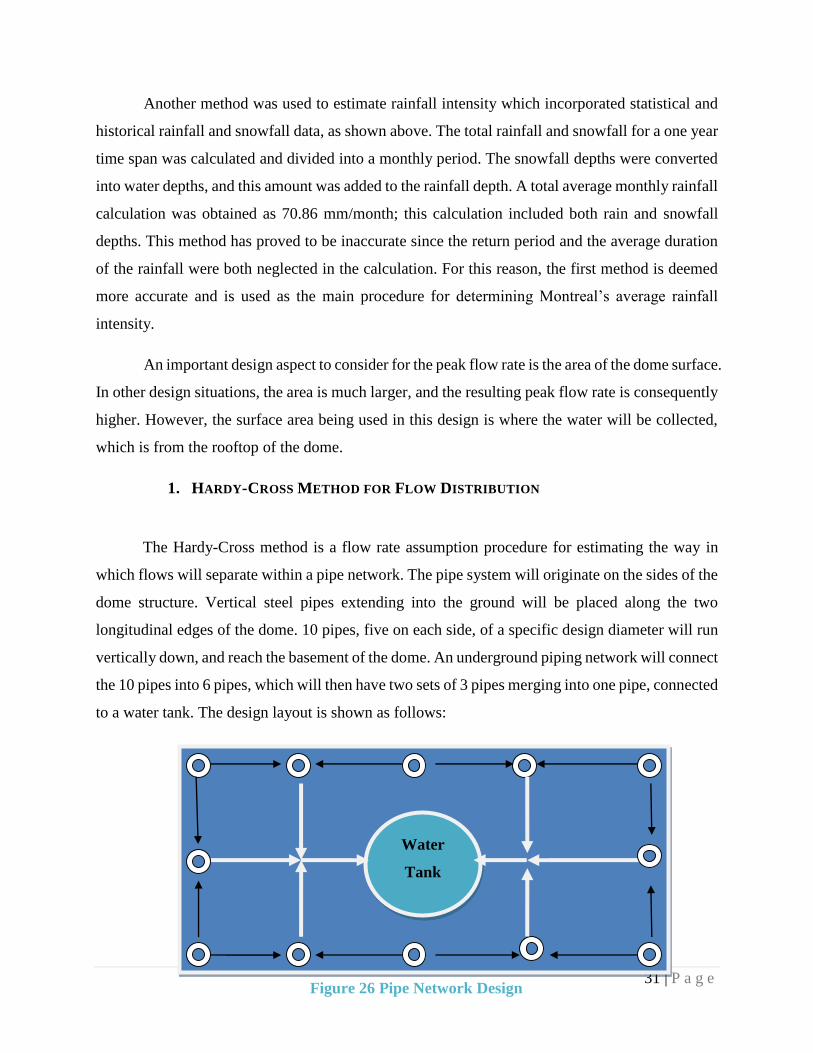
1. HARDY-CROSS METHOD FOR FLOW DISTRIBUTION
The Hardy-Cross method is a flow rate assumption procedure for estimating the way in
which flows will separate within a pipe network. The pipe system will originate on the sides of the
dome structure. Vertical steel pipes extending into the ground will be placed along the two
longitudinal edges of the dome. 10 pipes, five on each side, of a specific design diameter will run
vertically down, and reach the basement of the dome. An underground piping network will connect
the 10 pipes into 6 pipes, which will then have two sets of 3 pipes merging into one pipe, connected
to a water tank. The design layout is shown as follows:
Figure 26 Pipe Network Design
Water
Tank

32 | P a g e
The initial estimation is done using the Hardy-Cross method. The peak flow rate calculated
of 0.00604 m3/s is divided into 10 separate flow rates entering the vertical pipes. Therefore, the
individual flow rates entering are each 0.000604 m3/s. The assumption for estimating flow
distribution is that the entire flow rate will separate into 50% when it reaches the underground
piping system (shown as white arrows). In other words, 50% of 0.000604 m3/s will go to the left
pipe and the remaining 50% will enter the right pipe. This assumption is valid for all the outside
pipes, except for those pipes overlapping. In this case, all 0.000604 m3/s is assumed to enter the
second pipe, as well as the 50-50 left/right distribution. As a result, the flow rate is distributed
evenly and assumed to be balanced under the Hardy-Cross estimation method. This method for
estimating flow rate distribution is based on a 50% division of flow; this means that the flow
separates according to an assumption that every pipe opening intakes 50% of the incoming flow.
The initial flow rate, estimated as 0.000604 m3/s for each vertical pipe, eventually
accumulates to a flow rate of 0.00604 m3/s. The flow rate was assumed to divide into a 50%
division because this allows for maximum flow rate analysis. It is also much easier in terms of
analyzing the flow rate sequence, and since the total flow rate is the same, it is safe for one to
assume a 50% distribution within the pipes.
2. OPEN-CHANNEL FLOW
The initial phase of designing a pipe network is the type of flow occurring throughout the
channel. In this case, since rainwater will be collected and passed through a series of pipes, open-
channel flow design is chosen. The free flow is also estimated to fill the pipe at 2/3 the total cross-
sectional area. The design is therefore approximated as a partially-filled open channel pipe system.
Figure 27 Partially-filled Pipe [6]

33 | P a g e
The ration d/D of 2/3 is seen as the most reasonable approximation for open-channel pipes.
The rainfall intensity and duration are both unpredictable quantities which may differ from period
to period. The channel cannot be approximated as closed-channel because this limits the design to
one direction of analysis. Therefore, after several consultations with the hydraulics department of
the university, the estimation of 2/3 filled channel was chosen, since is provides a relatively even
assessment of open-channel flow with a pipe 2/3 fully filled.
3. PIPE DESIGN & MATERIAL
The pipe material was chosen based on reliability, strength, and economy. Although
aluminum and iron pipes were suitable for the design, corrugated commercial steel was chosen
because it is inexpensive, performs well under pressure, and fits reasonably with the overall dome
steel framework. Since the pipes on the outside will be connected to the steel framework, this will
also provide an aesthetic balance of material for the steel structure.
The design procedure was accomplished using the Manning’s equation for open-channel
flow. Manning’s equation related the roughness of the material, the hydraulic radius of the pipe,
as well as the slope of the pipe to obtain the velocity or flow rate required. In this case, the flow
rate (peak flow rate) is known; the only missing parameter is the diameter which is indirectly
obtained from the hydraulic radius.
For partially-filled pipes, the hydraulic radius is calculated using the following equation:
Rh (partially filled pipe) = 0.25 * (a - sina)/a * D
Where a is the internal angle illustrated between the arrows in figure 2, and D is the total pipe
diameter
The Manning’s equation is used to determine the design diameter, using 2/3 of the total area:
1/n *(0.25 * (1 - sin a)/a * D) 2/3 * (So) 0.5= Q / (2/3 * A)
Based on these two mentioned equations, a design formula was determined to design for
the required design diameter of the pipes. Referring to the Appendix, the outside pipe diameter for
the vertical pipes collecting the rainwater was designed to be 6 inches (168 mm diameter). This

34 | P a g e
design was based on combining the slope requirements and flow rate mergence from the rainfall.
In the underground pipe network, where all pipes of diameter 6 inches merge into one flow, as
shown in the figure, a larger diameter is required. Combining three flow rates Q1 + Q2 + Q3 will
result in a maximum flow of 0.00302 m3/s. From this design flow rate, a new equation is
formulated based on the design slope and Manning’s equation to find a suitable diameter. Referring
to the appendix, the design diameter is calculated to be 10 inches.
The ratio of d/D is that of the distance between the bottom of the pipe to the surface of the
water, with the total height or diameter of the pipe. The assumption used for this design is that d/D
is 2/3 or 67% full. This assumption is valid for partially-filled pipes. In order to determine the pipe
diameter, Manning’s equation is used, with a Manning’s friction coefficient of 0.024 for design n
in steel pipes.
The slope is determined according to the design layout of the dome’s interior area. The
height of the dome is 10 m, and the basement extends 4 m underground. Several trial and error
procedures have been made to obtain an optimal slope that will result in a large enough diameter
without great frictional losses. Horizontal pipes are found all around the pipe network, right below
the vertical connecting pipes. These horizontal pipes connect to 6 sloped pipes, two pairs of 2 on
the longer side of the dome, and one pair on each side on the short section of the dome, as shown
in the following figure.
The first slope is measured as 1.5/7 (0.214) whereas the second slope is 0.85/9 (0.0944).
Including sloped pipelines will increase the velocity and will provide kinetic energy from the
energy potential. However, to ensure a balanced increase in velocity that will not damage the steel
pipe, an expansion is designed between the two connecting sections to control the velocity increase.
In addition, the merging pipes will then connect horizontally (slope = 0) and lead to the collecting
water tank on both sides.
35 | P a g e
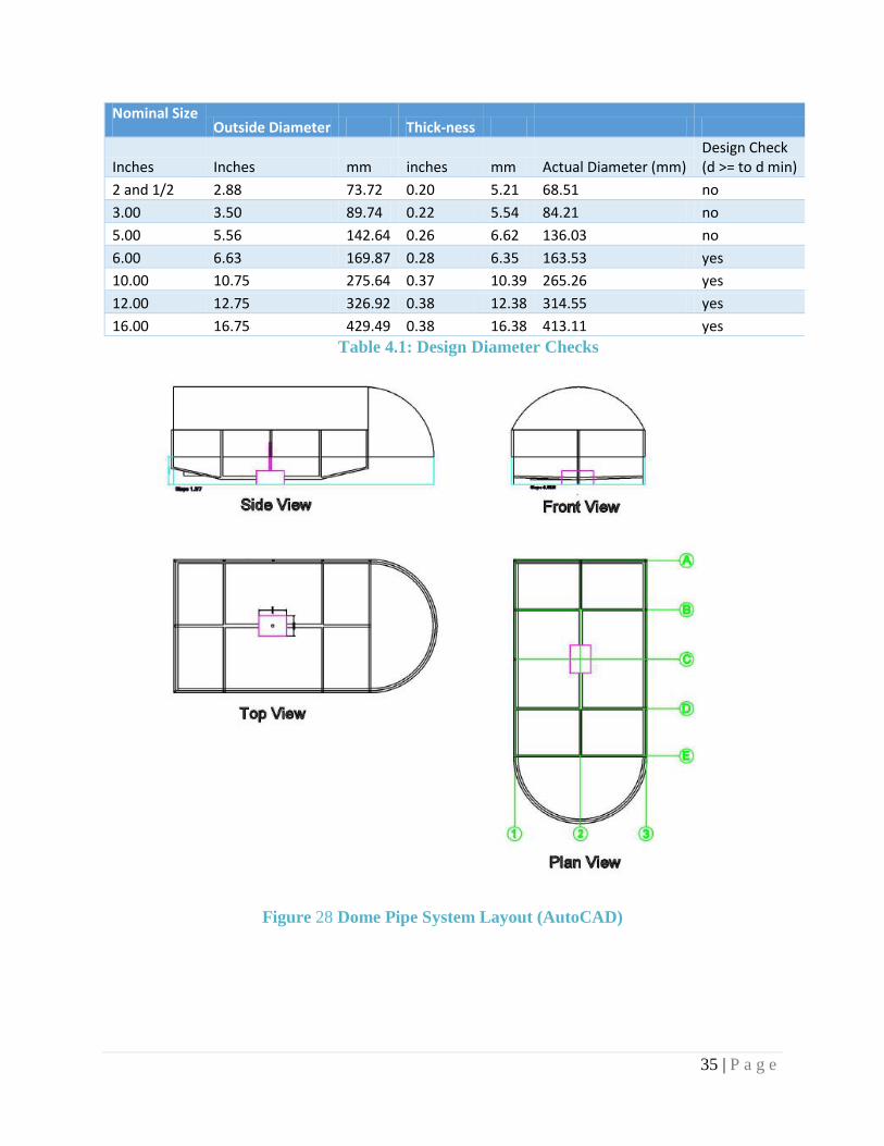
Nominal Size Outside Diameter Thick-ness
Inches Inches mm inches mm Actual Diameter (mm) Design Check (d >= to d min)
2 and 1/2 2.88 73.72 0.20 5.21 68.51 no
3.00 3.50 89.74 0.22 5.54 84.21 no
5.00 5.56 142.64 0.26 6.62 136.03 no
6.00 6.63 169.87 0.28 6.35 163.53 yes
10.00 10.75 275.64 0.37 10.39 265.26 yes
12.00 12.75 326.92 0.38 12.38 314.55 yes
16.00 16.75 429.49 0.38 16.38 413.11 yes
Table 4.1: Design Diameter Checks
Figure 28 Dome Pipe System Layout (AutoCAD)

36 | P a g e
4. PIPE FITTINGS & GUTTERS
According to the pipe network layout as well as the design diameters, pipe fittings are
drawn based on the required measurements. It is important to note that each pipe has an internal
and external diameter, due to the thickness of the pipe. Referring to the appendix, specific pipe
thicknesses have been used based on the desired design diameter. The 6-inch pipe has an external
diameter of 6.75 inches, and a thickness of 0.28 inches. The corner pipe fittings of 90 degree angles
will have three openings of 6 inch diameters: one at the top from the vertical pipe, and two on the
sides, connected to the left and right pipes respectively. The second type of pipe fitting is the
connection between left and right pipes to the central pipe, as shown as A-A’ in the layout. This
fitting has the same dimensions as the corner pipe, except the third opening will be a horizontal
central opening, rather than on the top. The third pipe fitting is the most complex, containing four
connections from the top, the two sides, and the center, of 6 inch diameters. Lastly, the system will
be connected to two individual pipes of 10 inch diameters, where the back side, front side, and left
and right sides will include openings. The only difference is that the front side will lead to the
water tank, and therefore will have the diameter of 10inches, whereas all the others will have a
diameter of 8 inches to merge into one large pipe of 10 inches.
The gutters for this specific pipe network layout depend on size, material, and gutter type.
The stainless steel U-shaped gutter is the most suitable type of gutter for the dome, since the
rounded nature of the gutter allows water to easily flow into the vertical pipe, which has a circular
cross-section and fits properly with the steel framework of the dome. The following image depicts
the type of connection designed for the gutter system around the dome.
Figure 29 U-Shaped Steel Gutter [7]

37 | P a g e
As shown above, the gutters will have a circular cross-section, of diameter 250 mm, based
on the calculated diameter for the vertical pipes. A gutter size of 250 mm is chosen to accommodate
the 6 inch (15 cm) diameter vertical pipes running vertically down the gutter system. The gutter
system will be supported by a series of half-round gutter brackets, also of 25 cm diameter. These
supports will run along the perimeter of the dome in order to sustain the steel gutter system. A
detailed drawing for the U-shaped gutter ad bracket has been provided in the appendix.
5. WATER RECYCLING & USAGE
The purpose of providing a rainwater harvesting system inside the dome building is to
recycle the water and benefit from its collection. Several uses can be made simply by filtering and
recycling the water, however due to limited water supply and design knowledge, the recycled water
may be used for supplying a central water fountain at the center of the dome, or for kitchen and
bathrooms situated inside the dome. The water tank collecting all the water from the runoff is
located in the basement. After a heavy rainfall, the water will flow into the two pipes connected to
the water tank, which will have sand filters along the cross-section between the water tank and the
pipes.
Rather than using water supply provided from water storage tanks, the proposed design
allows the dome to obtain its own water recycling system, where original rain water can be filtered
and used to supply small quantities where needed. Figure 3 describes the main procedure of
Figure 30 Longitude U-Shaped Gutter System Component [22]
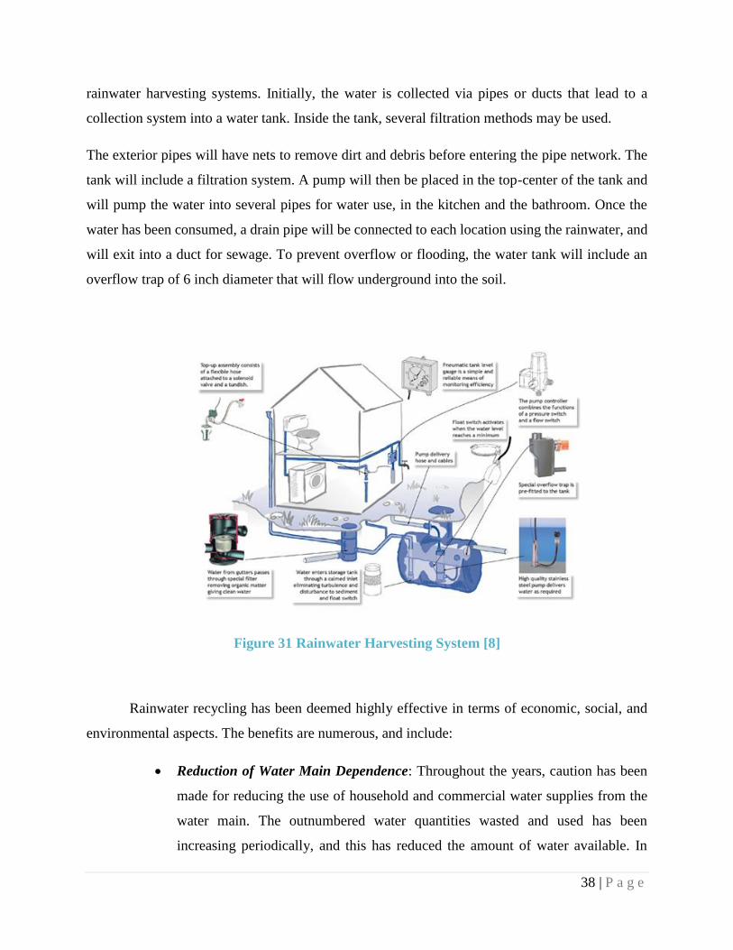
38 | P a g e
rainwater harvesting systems. Initially, the water is collected via pipes or ducts that lead to a
collection system into a water tank. Inside the tank, several filtration methods may be used.
The exterior pipes will have nets to remove dirt and debris before entering the pipe network. The
tank will include a filtration system. A pump will then be placed in the top-center of the tank and
will pump the water into several pipes for water use, in the kitchen and the bathroom. Once the
water has been consumed, a drain pipe will be connected to each location using the rainwater, and
will exit into a duct for sewage. To prevent overflow or flooding, the water tank will include an
overflow trap of 6 inch diameter that will flow underground into the soil.
Figure 31 Rainwater Harvesting System [8]
Rainwater recycling has been deemed highly effective in terms of economic, social, and
environmental aspects. The benefits are numerous, and include:
Reduction of Water Main Dependence: Throughout the years, caution has been
made for reducing the use of household and commercial water supplies from the
water main. The outnumbered water quantities wasted and used has been
increasing periodically, and this has reduced the amount of water available. In

39 | P a g e
order to promote sustainability, recycling rainwater will preserve the water supply
and benefit the environment by saving water supplies.
Economic and Sustainable: Collecting and recycling rainwater is beneficial for
reducing costs and wastage. The overall electricity bill is reduced when water is
recycled, since the water collected is free of charge. Although installation and
pump operating costs are required, these costs are minute in comparison to the total
energy savings for the dome.
Health Benefits to Society: Harvesting rainwater is said to be healthier for
individuals than the treated water supplies, of which undergo several filtration and
chemical treatment processes, such as purifying with chlorine and other hazardous
chemicals. Rainwater is more beneficial and provides a safe water and natural
water supply.
6. PUMP REQUIREMENTS
Laboratory experiments have been used to determine the power required to lift water in
horsepower. Since the two pipes carrying flow rates of 0.00302 m3/s will merge into one flow rate,
the total flow inside the tank will be 0.00604 m3/s. According to the calculated flow rate of 0.00604
m3/s, the conversion to gallons per minute becomes 95.8 gpm. This flow rate is high because the
rainwater flow rates from each of the ten exterior pipes will merge into one flow rate. Referring to
the Appendix, the table provided includes the flow rate and pumping height as variables to
determine the pumping power required. From double interpolation, with a pumping height of 4
meters (13 ft), the approximate horsepower required for the pump is 0.3416 hp. For safety and
economic measures, a ½ hp commercial submersible pump will be placed at the center of the tank
to pump the water into ducts, which will eventually flow water to supply the kitchen and bathrooms.
7. LOSSES IN PIPES
The two important aspects when determining losses in the pipe network designed are the
major and minor losses. Major losses, calculated using the Darcy-Weisbach Equation, are
frictional losses due to the length of the pipe. The minor losses are present from the bends, curves,

40 | P a g e
sudden expansions or contractions along a pipe. In this design, energy conservation and
minimization of energy losses must be taken into consideration.
For pipe flow, the optimal design is one which has the least major and minor losses. Material of
pipe, length, flow rate, and diameter are all important parameters influencing the losses in the pipe.
For the pipe network, individual minor and major losses were calculated based on the known flow
rate and design diameters.
Major Head Loss = HL = (f) X (L/D) (V2/2g), where f is the Darcy friction factor
Minor Head Loss = HL = (k) (V2)/2g, where k is the minor loss coefficient
According to the appendix, the losses for both lengths of the pipes and the bends and curves
are insignificantly low. This is because large losses come from long lengths of the pipes, over 100
m long, and the ones designed for this pipe system are altogether less than 100 m, which therefore
significantly reduces the frictional losses. In addition, the flow rate for each pipe is low compared
to average flow rates, since it was determined based on the rational method and intensity, and then
divided into 10 different flow rates. The total flow then reduces from 0.00604 to 0.000604 m^3/s,
or 0.64 L/s.
8. DESIGN LIMITATIONS AND DIFFICULTIES
The rainwater collection and harvesting system requires several design procedures and
considerations. The main difficulty arose when formulating a method to determine the design
diameter. Initial considerations were made regarding the type of channel flow for analysis. After
several consultations with the Hydraulics Department of Concordia University, the type of channel
most suitable for this pipe network was chosen as open-channel flow, with a d/D ratio of 2/3 (67%).
The approximation was considered to be most accurate since 67% is larger than a half-filled pipe
but smaller than a closed-channel flow analysis. From this chosen analysis, the Manning’s equation
was the acceptable method to determine the design diameter from the calculated flow rate.
Furthermore, since the basis of all analysis and design calculations originates from the flow
rate, Q, the method to determine the most accurate flow rate was another limitation for the pipe

41 | P a g e
network design. Although numerous methods and research formalities exist to estimate peak flow
rates and rainfall intensities, the design was limited to the procedures learnt in the “Water
Resources Engineering” course. The rational method for estimating peak flow rate was used,
however the rainfall intensity was difficult to calculate. Three different techniques were used to
estimate rainfall intensity, all of which resulted in different measurements. In addition, snowfall
was also taken into consideration in some procedures, but neglected in others. Overall, the most
accurate method for rainfall intensity calculation was chosen based on the Montreal region, return
period, and rainfall duration. These variables were tabulated and the rainfall intensity was
calculated for a 10-year return period of 60-min storm duration, which was most reasonable.
An additional calculation concern resulted in the analysis of the pipe network. The water
velocities inside pipes, according to laboratory research, ranges between 1-3 m/s. When the
velocities were calculated according to the diameter cross-sectional areas and flow rates, the
velocity was very low in comparison to the usual range. This problem was due to the flow rate
distributions along the pipe, as well as from the overdesign of the pipe diameters to prevent
overflow and corrosion. A design buffer time is included to slow down the velocity as the water is
collected along the steel gutters. This buffer time allows the rainwater to reach the vertical pipes
at a reasonable velocity, within the acceptable range. Converting the potential energy to the kinetic
energy also allows one to determine the speed of the water flowing down. Due to the buffer time,
the velocity is stabilized and the results become reasonable. In addition, the pressure drop between
the pipes is very low; roughly 0.05 Pa along one pipe connection. With a small Darcy friction
factor, and a low flow rate, the total pressure difference between the 7 m pipe of Q = 0.001208
m3/s is almost negligible.
9. RESOURCES USED FOR DESIGN
The pipe network design has been designed according to the nominal pipe diameters,
Manning’s equation for open-channel flow, the Hardy-Cross method for estimating flow rate
distribution, the rational method for estimating peak flow, and the Hazen-Williams equation for
calculating frictional losses. With the aid of research, scholarly articles and texts, as well as
individual consultations with professors from Concordia University, the network has been
designed. Dr. Samuel Li, Dr. Han, as well as Dr. Catherine Mulligan are the faculty members that
42 | P a g e
guided the design process and answered any questions or concerns regarding the design
considerations.
Several useful handbooks and text material served as an aid to the design process, including
the “Water Resources Engineering” textbook by Wurbs and James, as well as nominal pipe ASTM
standards. In addition, online research regarding pipe network design and analysis was done for
ensuring that correct procedures were followed. Rainwater recycling was another key research
item for designing the rainwater collection system.
10. LEADERSHIP IN ENERGY AND ENVIRONMENTAL DESIGN (LEED)
The objective for designing and constructing the glass dome in the center of Concordia
University’s future headquarters is principally to have an environmentally sustainable,
aesthetically pleasing, LEED building for faculty, staff, students, and visitors. With the increasing
concern for the environment becoming a central design consideration for architects and engineers,
it is with no doubt that the new innovative buildings being designed nowadays must incorporate
LEED standards. Several aspects have been taken into consideration to gain LEED certification.
The glass dome’s environmentally sustainable characteristics have been outlined in the following
section. The main points were adapted from the Construction Week Article as well as the U.S
Green Building Council on Leed Certification [9].
1. Site selection: The Grey Nun’s site location, along Rene-Levesque and St. Mathieu, with a
proximity to the main St. Catherine’s street, is a grey area, since it is far from sensitive areas
like “farmland, flood zone, endangered species habitat, and wetlands” This site selection is
therefore safe for humans and protects the habitat by not conflicting with natural areas [10]

43 | P a g e
2. Density and community connectivity: For the site to be deemed community-connected, it
must be within 0.8 km radius of at least “10 basic services and 3 residential zones”. The Grey
Nun’s building is located less than 0.5 km away from basic services offered on St. Catherine
Street, as well 1 km away from residential duplexes on St. Mathieu Street.
As displayed in Figure 32, the
proximity to both basic services along
St. Catherine Street and Rene-
Levesque provide nearby access from
the Grey Nuns building. In addition,
several residential duplexes are
located around the Grey Nuns
building, along St. Mathieu and St.
Marc.
3. Alternative transportation, public transportation access, parking capacity: This site is
located in the central downtown area of Montreal, with a minimum of 3 bus lines, and 2 metro
stations (Peel and Guy-Concordia), as well as Lucien-L’Allier metro station slightly further on
Rene-Levesque street.
4. Rainwater management: A rainwater recycling and collection system has been designed
using ASTM pipe measurements, which allows rainwater to enter the building and reach an
underground piping system for filtration. The collected water will then be pumped up to the
ground floor of the building for water usage.
5. Building Daylight Maximization: The entire surface area of the dome is composed of glass
material for glazing. This allows constant supply of daylight into the building as well as heat.
The solar energy provided by the sun entering the dome will account for maximal energy
savings on electricity and heat.
Figure 32 Grey Nun’s Building Map

44 | P a g e
6. Storage and collection of recyclables: Storage bins for three individual materials (plastics,
paper, and garbage) will be placed in 5 locations around the dome to encourage compost and
recycling.
7. Building reuse: The demolished kitchen building will contain several materials (concrete, steel,
brick, wood, pipes) that may be reused for the construction of the dome or the renovation of the
GN Building. Roughly 15% of the demolished material will be inputted into the new
construction inside the concrete mix for columns and slabs.
8. Construction waste management: The waste generated from the excavation, demolition, and
construction processes will be redirected to manufacturing industries to recover the resources
rather than placed into landfills and incinerators.
9. Regional materials: Building materials such as concrete, steel, stainless steel pipes, storage
tanks, pumps, glass, and steel staircase models are all from regional companies (around the
Montreal region) to encourage local industrial development.
10. Parking and Open Space: Extra parking spaces as well as green area were included in the
design to allow easy access to and from the GN and dome buildings; bike racks are to be
installed near the park behind the GN building, where the dome is placed to encourage
alternative green transportation modes.

45 | P a g e
5.0 TUNNEL
5.1 Introduction
The Montreal region experiences extreme temperatures in both summer and winter
conditions. Exterior passageways have an increased amount of traffic during the academic year,
and this decreases travel convenience for students and staff. A solution to both the traffic and
climate concerns is the construction of an underground tunnel, initiating from the basement
extremity of the GN F-wing building and merging onto the Toronto Dominion Bank Building (TD),
along the Ste. Catherine and Guy Street intersection. A similar tunnel, connecting the TD Bank
building with the previously constructed MB Building tunnel, is a proposed design from another
coordinating civil engineering team. This team project coordination facilitates both designs since
the tunnel connection will serve as a comfortable
passageway from the GN building to across the MB
building, which already has an easy access to Guy-
Metro and the rest of Concordia University.
The proposed 200-meter-long underground
tunnel runs parallel to Guy St. and intersects St.
Catherine Street and connects to the TD Bank
building as shown in Figure 33Error! Reference
source not found.. The purpose of the tunnel is to
provide residents and faculty of Concordia
University a safe and easy access to the Guy-
Concordia Metro and to the rest of Concordia
University. Furthermore, it will decrease the
pedestrian traffic on the main roads especially during
rain and winter seasons. With the Administration & Governance office and a Cafeteria in the Grey
Nun’s building it’s also necessary that Chartwells, Concordia’s on-campus food services, and
Concordia’s courier service have a passage for them to make their necessary deliveries.
Figure 33 Map of Tunnel

46 | P a g e
5.2 Geotechnical Report
Since a thorough site investigation was not performed due to limited resources and time,
the previous geotechnical report of the Hall building tunnel was used as a reference. According to
the geotechnical report, the site condition consist of a fill layer, glacial till layer, and the bedrock
layer. The fill layer consists of loose to compact brown silts and sand. Furthermore, three to four
inches of asphalt pavement and 6 to 12 inches thick reinforced concrete slab layer was found
resting on top of the fill layer. Compacted to very dense glacial till, which is composition of sand
silt and some gravel, was found at 2.3ft to 4ft, and as the depth increases glacial till becomes
coarser. The bedrock is clayey limestone approximately at 18 to 27ft elevation and according to
the report it is of good quality. Moreover there is also groundwater at about 18 to 22ft depth.
5.3 Load Calculations
The loads on the tunnel are the self-weight of the tunnel, soil pressure, and the truck load.
There are two types of load that were accounted for: live and dead load. For simplification of the
design and analysis purpose, all loads were based on a meter strip. The live load was considered
as the maximum truck load that a tunnel will have to withstand. It was assumed that the heaviest
truck on Rue Guy and Rue St. Catherine would be a triaxial truck. According to the Vehicle Load
and Size Limits Guide of Quebec,
a trixial truck has a weight of
15500kg [11]. Any moving load
was not accounted for since the
depth of the tunnel is 3.0m (10ft)
and has minimal effect on the
tunnel. Additionally, all live
loads were increased with a
factor of 1.7 and all dead loads
were increased with a factor of
1.25 as prescribed as by the Canadian Highway Bridge Code Design Code [12]. The analysis of
the tunnel was done on SAP2000, where it was design as a frame and all loads were inputted in
kilo-newton per meter. To consider the uplift force on the tunnel from the soil below in the
Figure 34 Load Summary

47 | P a g e
SAP2000 model, springs, with a subgrade reaction of 20MN, were assigned to the bottom frame
[13]. Furthermore, according to the geotechnical report, it was advised that for load analysis
purposes, earth pressure coefficient at rest (Ko) for fill material should be considered instead of
active earth pressure coefficient (Ka).
5.4 Tunnel Properties and Assumptions
The tunnel dimensions were based on the current hall building-Guy Concordia Metro. The
cross sectional dimension of the tunnel are 4.55m width with a height of 3.4m. The clear span of
the tunnel is 2.6m and the height is 3.0m. The thickness of the slabs and wall are 0.4m which were
approximated. The tunnel was designed as a concrete box frame and analyzed as slabs and
basement walls, with concrete strength to be 30MPa and steel strength to be 400MPa. It was also
assumed that the geotechnical properties were similar to the properties of the Hall building tunnel
because of the close proximity. Through collaboration with team four member, Julien, and the
geotechnical report it was decided that since the water table is close to the bedrock, it will be
drained out using a simple piping system. This decision was taken to eliminate design and analysis
complication due to water, since the water table above the bedrock is about two to three feet,
knowing that the tunnel is one to two feet above the bedrock. Refer to the appendix for the final
design of the tunnel.
Figure 35 Tunnel Cross Section

48 | P a g e
5.5 Alternative Tunnel Design
Initially the design of tunnel was assumed as a beam column structure. The preliminary
calculations for the structure were done based on the final load calculations. The beam column
connections were pinned on the top therefore the axial load on the column was determined by
calculating the reactions of the simply supported beam. The fixed end moments were determined
by the Moment Distribution Method. Please refer to the appendix for sample calculations of the
beam column design. For the analysis of the tunnel, the structure was modeled on ETABS as a
frame with both top ends with pin connections and fixed supports at the bottom ends of the frame.
According to the bending moment diagram from ETABS results (Figure 36) there is no moment
at section A and B due to the pin connections thus no moment transfer in the column. Therefore,
the moment at the mid span is increased compared to the actual moment on the top slab of the
tunnel. Hence, the beam column analysis for the tunnel was not appropriate. The tunnel was
redesigned as a combination of slabs and basement walls as recommended by Dr. Galal, professor
at Concordia University.
Figure 36: Bending Moment Diagram Generated by ETABS for Alternative Design

49 | P a g e
6.0 COMPREHENSIVE COST ANALYSIS
For a project of this complexity, a detailed cost estimate is required for each of the 3 main
components of the project. Each component of the construction process had to be measured out
and recorded into a thorough quantity take-off. Unit costs then required applying final costs to the
quantities measured in the take-off. These costs were combined in order to achieve a final
construction cost for each of the sections of the project in order to determine the feasibility of the
project, as well as aid in the production of a comprehensive and realistic project schedule.
6.1 WinEstimator Software
The majority of the estimate was completed using a high quality estimating software;
WinEstimator. This software uses a virtual quantity take-off which allows the user to import
AutoCAD drawings of the construction documents, scale the drawings based on the proper
dimensions and measure lengths or areas of the construction components required for the project.
For example, the renovation of the GN building required the installation of a new steel deck for
each floor of the building. Using WinEst, the thickness of the slab was entered, the materials
needed, such as 30 MPa concrete with aggregate, structural steel decking, sprayed fireproofing,
welded wire mesh and finishing were chosen, and the area of the slab was digitized as seen in
Figure 377. The program combines this data and outputs quantities for each of the selected
materials under a specific assembly name “Slab on Deck”, which can then be detailed further by
noting the location as “GN2” and the work breakdown structure as “Structural Components” as
seen in Figure 388. These details allow for the final quantities to be shown either in their entirety
in a typical CSI Hierarchy, or organized based on specific sections of the work such as the total
cost of the structural components of the GN building reconstruction.

50 | P a g e
Many sections of the estimate were completed using WinEst; demolition, interior finishing,
structural steel, slabs, precast concrete, millwork, interior glazing, excavation and generalized
pricing for mechanical and electrical components. These items were priced based on typical unit
costs from similar historical construction projects. The majority of these construction materials are
used in almost every construction project and average prices were readily available. Though
constructing an underground tunnel in an occupied urban atmosphere is a complicated procedure,
the materials and work needed to be done are fairly typical and require commonly used processes
such as; excavation, precast concrete sections, cement finishing, waterproofing and paving. The
complete 20 page quantity take-off was transferred to Excel format and can be found in the
appendix.
Figure 37 WinEst Virtual Take-Off Slab Area Example
Figure 38 Slab on Deck Assembly Example on WinEst

51 | P a g e
6.2 Subcontractor Price Quotations
Other components of this construction were more complex and could not be priced based
on historical projects due to the uniqueness of this project. These prices had to be obtained through
quotations from subcontracted specialty companies that could supply a more realistic price for
work of this scale. The first company that provided a quotation was Vergo Construction for the
supply and installation of the 260 m2, 224-seat auditorium; which was designed including the
necessary structure, seating and speaker’s podium. Due to the work needed to put the building to
code and construct the auditorium in a structure this old, the price was more than a typical
auditorium would cost. The final price was entered at $1.4M for the entirety of the work which
spans over 2 stories.
The second specialty contractor that was planned to provide a quotation for this project
was Seele, a company at the forefront of the specialty structural steel and glazing industry having
completed a number of glass dome projects of similar nature and far bigger size. The slab beneath
the dome was priced using WinEst. As for the quantities, the dome was calculated to have over
1,370 m2 of steel and glass. Unfortunately, Seele was unable to provide a proper quotation in time
for the final estimate, but an estimated cost of $600,000 was provided by a Concordia University
Professor. Along with the remainder of the work, the total cost of the dome was entered at slightly
under $1.1M.
6.3 Total Estimated Cost Analysis
The cost estimate was completed once the unit prices and quoted prices were entered into
WinEstimator and the final cost breakdown was completed. All labor and materials were taken
into account for the completion of the cost analysis, though certain components such as
contingencies, general conditions, permits and precise mechanical, electrical and plumbing prices
were not included which would increase the total cost of the project considerably.
The final cost of the GN building renovation is $9,130,285 which includes demolition, as
well as structural and interior renovation. The total cost of the Dome was found to be $1,078,586
which includes the addition of a kitchen to the basement, the slab, the structure, glazing and interior
finishing. The total cost of materials and labor of the tunnel was found to be $2,795,205 which
includes the excavation, concrete, interior finishing and hard landscaping. This brings the total
project cost to $13,010,601 for which a general cost breakdown for each section
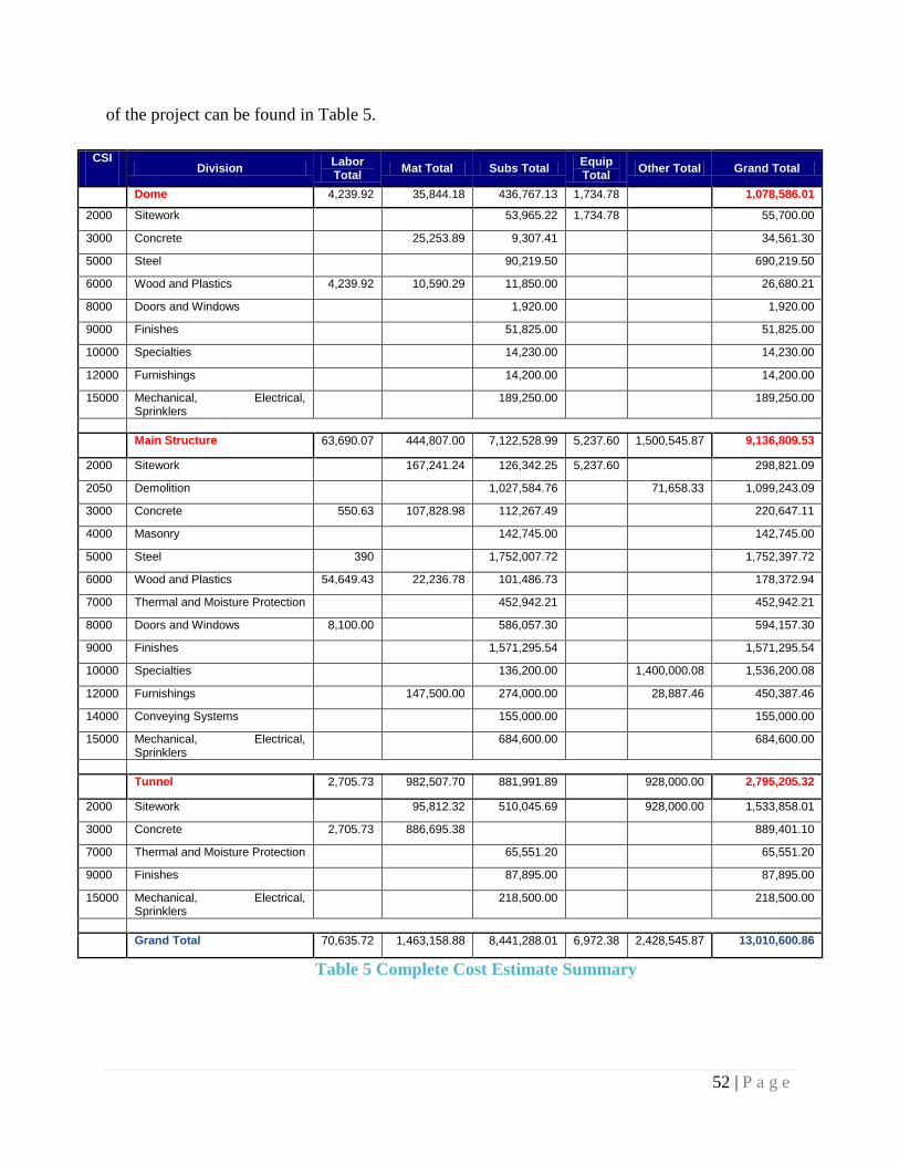
52 | P a g e
of the project can be found in Table 5.
Table 5 Complete Cost Estimate Summary
CSI Division
Labor Total
Mat Total Subs Total Equip Total
Other Total Grand Total
Dome 4,239.92 35,844.18 436,767.13 1,734.78 1,078,586.01
2000 Sitework 53,965.22 1,734.78 55,700.00
3000 Concrete 25,253.89 9,307.41 34,561.30
5000 Steel 90,219.50 690,219.50
6000 Wood and Plastics 4,239.92 10,590.29 11,850.00 26,680.21
8000 Doors and Windows 1,920.00 1,920.00
9000 Finishes 51,825.00 51,825.00
10000 Specialties 14,230.00 14,230.00
12000 Furnishings 14,200.00 14,200.00
15000 Mechanical, Electrical, Sprinklers
189,250.00 189,250.00
Main Structure 63,690.07 444,807.00 7,122,528.99 5,237.60 1,500,545.87 9,136,809.53
2000 Sitework 167,241.24 126,342.25 5,237.60 298,821.09
2050 Demolition 1,027,584.76 71,658.33 1,099,243.09
3000 Concrete 550.63 107,828.98 112,267.49 220,647.11
4000 Masonry 142,745.00 142,745.00
5000 Steel 390 1,752,007.72 1,752,397.72
6000 Wood and Plastics 54,649.43 22,236.78 101,486.73 178,372.94
7000 Thermal and Moisture Protection 452,942.21 452,942.21
8000 Doors and Windows 8,100.00 586,057.30 594,157.30
9000 Finishes 1,571,295.54 1,571,295.54
10000 Specialties 136,200.00 1,400,000.08 1,536,200.08
12000 Furnishings 147,500.00 274,000.00 28,887.46 450,387.46
14000 Conveying Systems 155,000.00 155,000.00
15000 Mechanical, Electrical, Sprinklers
684,600.00 684,600.00
Tunnel 2,705.73 982,507.70 881,991.89 928,000.00 2,795,205.32
2000 Sitework 95,812.32 510,045.69 928,000.00 1,533,858.01
3000 Concrete 2,705.73 886,695.38 889,401.10
7000 Thermal and Moisture Protection 65,551.20 65,551.20
9000 Finishes 87,895.00 87,895.00
15000 Mechanical, Electrical, Sprinklers
218,500.00 218,500.00
Grand Total 70,635.72 1,463,158.88 8,441,288.01 6,972.38 2,428,545.87 13,010,600.86

53 | P a g e
7.0 CONSTRUCTION PROCESSES: TUNNEL
The construction of the precast tunnel from the GN building to the TD Bank building will
require several important steps in the construction process in order to minimize the necessary road
closures to downtown Montreal roads. In order to decrease road closures on the most trafficked
street that the tunnel will encounter, Ste. Catherine street, the excavation work will begin at the
South-most point of the tunnel, at the entrance to the Grey Nuns facility.
7.1 Excavation
The first step in the excavation process is the
pulverization of the existing asphalt pavement. This will
be done using a Caterpillar RM500 Rotary Mixer. This
material is then loaded into a Freight Liner dump truck
to be hauled off-site. Once the pavement has been
removed, a Caterpillar 390 DL Hydraulic Excavator
will be used to dig a trench of approximately 6.3m x
6.3m. The width of this trench is to accommodate the
4.5m width of the precast tunnel sections as well as
extra working space for the crew who will work around
these precast sections once they have
been placed. The depth is to include
the 3.5m height of the precast, as well
as extra depth for the stone placed
below the tunnel, along with a layer of
backfill, crushed stone and a new layer
of heavy duty asphalt pavement. The
majority of this material will be hauled
off-site, though a part of it will be left
in-place to be used as backfill on either
side of the tunnel. The trench will
have vertical walls due to the fact that
Figure 39 Caterpillar RM500 Asphalt
Pulverization Process. [15]
Figure 40 Caterpillar 30 DL Hydraulic Excavator. [15]

54 | P a g e
the number of lanes to be closed on Guy street must be minimized. In order to accommodate this,
trench sheets with large horizontal hydraulic braces will be used to shore the trench and hold back
the earth from the remainder of the road during construction. This shoring technique allows for a
wide span to allow space for insertion of the precast sections.
7.2 Precast Concrete Placement
Once a section of excavation is completed, a
second crew will enter the trench to place a 12” layer
of clean net stone throughout the trench in order to
prepare the ground to receive the weight of the tunnel
sections without any risk of future settlement. As the
excavation crews progress, precast sections of
dimension 4.5m x 3.5m x 3.0m will arrive on trucks
where each truck has a capacity of 3 sections per haul.
A Liebherr LTR 1060 crawler crane will be used to
lower each 80 ton section into place. The crane will
move along the trench placing sections as a hydraulic
excavator is used to push the section together into
place. The joints are then sealed with waterproofing
and shotcrete on both the interior and exterior of the
tunnel.
7.3 Paving & Finishing
The crews continue the cycle of excavation, precast sections and waterproofing as the
tunnel progresses until the entire length of the tunnel is complete. At this point the shoring is
removed and the sides of the trench are backfilled with the remaining excavated material. The
tunnel will also receive 1m of this material on top of the entire trench. Enough space is left above
the tunnel to lay down an 0.5m thick sub base layer of 0-56mm crushed aggregate, followed by a
0.15m thick base layer of 0-20mm crushed aggregate. These layers are to prepare the ground for
the application of heavy duty asphalt pavement, which will be placed using a Caterpillar AP500E
Asphalt Paver.
Figure 40 Liebherr LTR 1060 Telescopic
Crawler Crane [17]

55 | P a g e
Once the roads have been paved, the public will regain
access to the roads above the tunnel. At this point interior
finishing and electrical work can be completed in the
tunnel as these are the least vital phases of the work in
terms of road closures. The concrete will be sealed;
lighting, ceramic tile flooring, doors & wall coverings
will be installed and the tunnel will be completed in its
entirety. The tunnel will connect at one end to the TD
Bank building basement which will have already been
renovated. The other end will attach to the basement
lobby elevators which will access the main ground floor
lobby.
Figure 41: Caterpillar Ap500e Asphalt Paver [18]

56 | P a g e
8.0 CONSTRUCTION PROCESSES: GN BUILDING
8.1 Demolition of the Kitchen Building
The kitchen building is the two-story plus basement structure that was built as an addition
to the main GN building in the 1940’s. The main GN building is protected by the Ministry of
Culture as a historical landmark and cannot be touched, but the protection does not extend to the
kitchen building, which was built much later and presents no historical value. Therefore, it will be
demolished to make way for the renovations. However, the demolition will be partial, because the
basement of the structure will be reused in the dome. To tear down the walls, it is suitable to use a
method that would not endanger the basement from cave-ins, as well as provide a green alternative
to the traditional method. Therefore the selective demolition method is the most suitable for this
project.
Since the kitchen building is attached to the main compound by a ground floor tunnel,
before beginning construction of the dome, the opening left from the demolition of the tunnel will
be used for any work related to demolition and structural reconstruction. This will be the ideal
solution considering that the main building facade cannot be touched, and therefore the largest
opening available to work with will be the tunnel wall.
8.2 Demolition and Replacement of Structural Components
The entire project is considered a green initiative project. Therefore, it would be suitable
to employ selective demolition and attempt to recycle/repurpose the salvaged materials. This
would be an environmentally friendly solution for a green space such as the new GN building. The
demolished materials will have one location to enter and exit the building - the tunnel opening
connecting the GN building to the kitchen building. This opening will be extended upward
throughout all 5 floors of work in order to allow access to the equipment required for the
demolition and installation of a new structure. The stones that are removed from this exterior wall
will be recuperated and replaced once the work is completed, these walls can be removed because
they are in the inner courtyard of the building.
The perimeter structural steel columns in the existing building cannot be removed due to
the preservation of the exterior walls. The column design was done based on a completely new
structure, but in practice the columns will be reinforced by welding additional steel plates onto the

57 | P a g e
existing steel members in order for the structure to achieve and equivalent strength to the new
design. The interior columns that can be removed and replaced will be demolished and replaced
by temporary columns to support the slab until the new structural steel members are in place. The
new steel slab on deck cannot be installed using a crane due to the existing roof to be preserved,
therefore the crew will construct a temporary access ramp using steel and lumber in order to be
able to install the sheets of steel deck individually. These sheets are placed in an interlocking
pattern and a layer of reinforced concrete is poured on top of the steel in order to achieve the
necessary strength from the new slab. As one section of the existing slab is demolished and
removed from the building, the columns beneath it are being reinforced or replaced based on their
location. The new slab is then installed and filled with concrete for that particular section. The four
floors of slabs will have a staggered pattern of slab sections that will alternate being demolished
and replaced in an order than will ensure constant structural integrity of the building. This will be
the most efficient way of installing such a large amount of structural steel into a building in this
condition. Structural steel reinforcement will be the longest and most tedious step in the
reconstruction of the GN building as the careful removal and replacement of the structure must be
done slowly in a confined space.
8.3 Interior Finishing & Landscaping
Once the complex structural renovation is complete, sprayed fireproofing will be applied
to the structure where necessary throughout the empty building. Interior finishing is the next step
is the process of renovating the GN building; the drywall will be the first item to be installed. The
exterior walls will be cladded with exterior sheathing, batt insulation, vapour barrier, steel studs
and painted interior drywall. The interior walls will be constructed according to building standards
with fire resistant walls around corridors and stairs, as well as sound insulated walls between
offices for a quiet working environment. Once the drywall is installed, many of the remaining
interior finishes will be installed simultaneously by several subcontractors. First the lighting will
be installed, followed by the ceilings, floors finishes, miscellaneous metals, elevators, interior
glazing, doors, painting and finally the millwork and furniture will be installed.

58 | P a g e
While the interior
renovation is reaching its final
stages, the exterior landscape of
the land will be renovated to
create access to the site as it was
designed. New access roads will
be constructed to connect the
exterior parking to Guy Street,
new cast in place concrete curbs
will be installed using a Power
Curber 5700C, concrete sidewalks will be installed and trees/shrubs will be planted along the
perimeter of the property.
9.0 CONSTRUCTION PROCESSES: DOME
9.1 Destruction of Existing Building
The existing building on site of future glass dome is the kitchen building, whose demolition
process has been discussed in section 8.1.
9.2 Handling of debris
In the selective demolition approach, the structure is disassembled carefully, to facilitate
recycling and refurbishing of the construction materials. So the debris will be carefully sorted and
hauled away for their respective purpose. This will be done for the entire 2 story, 1000 m2 building
until only the ground floor slab remains. The basement kitchen equipment will be stored and reused
while the slab is being demolished using a hydraulic excavator with a breaking attachment. The
concrete slab material will be collected and hauled off site while trying to minimize damage to the
basement below.
9.3 Erection of the Dome Structure
Once demolition is complete, jacks will be placed in the kitchen basement in order to
support formwork for the pouring of a new concrete floor slab. The formwork will be installed and
30 MPA concrete will be poured into a semi-rectangular, semi-ovular shape.
Figure 42 Power Curber 5700C Cast In Place Concrete Curb
Fabricator. [19]

59 | P a g e
Once the work on the slab is finished, the work on the structure of the dome can start. First it will
be necessary to secure the base plates around the ring beam. The ring beam is the structure along
the bottom perimeter of the dome that will serve as anchor for the steel frame and will support the
dome. Then, a crane will be used to erect the steel components. Multiple crews will anchor the
first level of steel into the concrete deck. The following sections will be raised, fitted and fastened
into place as done with a typical steel structure. In order to ensure the stability of the structure,
the long cylindrical portion of the structure will be built followed by the rounded end-section. The
crane will be kept in place and will be used by another set of construction crews who will install
the exterior glazing. After the steel framing is complete, it will be necessary to put in place the
space framing structure which will be the one directly supporting the glass. The space framing is
a structure that is essentially supported at the nodes of the main steel structure and is elevated from
the main steel structure. Its purpose is solely to support the glass panels, which it holds with
fasteners and gasket lining. Then, the rectangular and triangular glass sections will be hooked to
the crane by one crew, raised into place by a second crew, and fitted into place by a third and final
set of workers. The last step of the construction process is to apply sealant to the top of the glass
structure to ensure its water tightness and protection.
Once the structural steel and glazing have been erected, interior finishing is the final step
in the construction of the dome. The basement will be repaired depending on the extent of the
damage caused by the construction process. The existing kitchen equipment will be placed back
into the newly renovated kitchen. The interior of the dome will have floor finishes, fountain
systems, washrooms and furnishings put in place in order to finalize the construction of the dome
building.
10.0 GANTT CHART FOR WORK SCHEDULE
A project with three distinct sections required a schedule for the simultaneous construction
of each component of the project. A start date of June 3rd, 2013 was decided for all parts of the
project in order to minimize work to be done in winter conditions. The tunnel was scheduled to be
installed fairly rapidly due to the speed of precast section placement in comparison to the cast in
place tunnel option. Excavation and shoring durations were determined based on the length and
area of work to be completed. It was assumed that three sections of the precast tunnel could be

60 | P a g e
placed per day. This was used in order to determine the time required to install the tunnel in its
entirety. The remainder of the work for the tunnel was scheduled based on typical construction
production rates due to the commonality of the work left to be done. The resulting duration of the
tunnel construction was 6.5 months, which was comprised of 130 work days and 6 months of road
closures for which the completed schedule can be found on Figure 44.
The construction of the dome and the renovation of the GN building were scheduled to be
done simultaneously and in close proximity, the Gantt charts are therefore represented together in
order to follow the progress of both works. The demolition and structural reinforcement of the GN
building are the most lucrative and time-consuming processes in the schedule. The installation of
new slabs and reinforcement of existing columns require much more time than what is required
for a new construction. The dome construction can only begin several months after the GN
reconstruction has begun in order to allow access through an opening in the building for demolition
and structural work. Once these tasks are nearing completion, the large-scale interior finishing
work can begin in order to complete the GN building as per the designs.
The structural steel and glazing of the dome are the only activities that did not have typical
durations based on historical projects. The complexity of the structural work lead to the assumption
of added time to the schedule for this unique construction. The interior finishing of the dome was
designed to be very simple and the work will, in turn, be done very quickly once the structure has
been mounted. The schedule that was produced based on the combination of these activities
resulted in a total project duration of 11 months. The GN building will require the entire 11 months
to renovate, including 240 days of labor. The dome will only require 7 months to construct but
will be completed at the same time as the GN building due to the delayed construction start date.
The combined schedule for both of these project components can be found on Figure 45.

61 | P a g e
Fig
ure
43 G
an
tt C
hart
for
Tu
nn
el C
on
stru
ctio
n
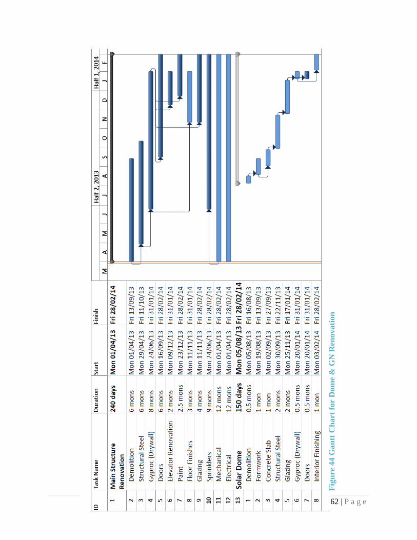
62 | P a g e
Fig
ure
44 G
an
tt C
hart
for
Do
me
& G
N R
enova
tion

63 | P a g e
11.0 REFERENCES
[1] CISC, Steel Handbook Of Steel Construction, CISC, 2008.
[2] CANAM, "Steel Deck," 02 2006. [Online]. Available: http://www.canam-
steeljoist.ws/www/v4/epublica.nsf/va_doc/722FD94ACC3827798525796B004D90E2/$File/et
abliercan.pdf. [Accessed 10 02 2013].
[3] Nazmiya Antiques, "Indoor Garden Spaces Interior Design," [Online]. Available:
http://nazmiyalantiquerugs.com/blog/2011/11/indoor-garden-spaces-interior-design/.
[4] GrabCAD, "Steel Frame Structure," [Online]. Available: http://grabcad.com/library/dome--2.
[5] "Triodectic Node and Connection," TATA Steel, [Online]. Available:
http://www.tatasteelconstruction.com/file_source/Images/Construction/Reference/architectural
%20studio/design/3.9.12.jpg. [Accessed 21st March 2013].
[6] H. Bengtson, "Spreadsheet Use for Partially Filled Pipe Calculations," [Online]. Available:
http://www.cedengineering.com/upload/Partially%20Full%20Pipe%20Flow%20Calculations.p
df.
[7] KME, "Architecture and Building: Gutter," 2012. [Online]. Available:
http://www.kme.com/en/rainwatersystem-gutters.
[8] Docstoc, "Rainwater Harvesting System," [Online]. Available:
http://www.docstoc.com/docs/22304257/A-typical-domestic-rainwater-harvesting-system-
based-on-an-underground-GRP-storage-tank-WISY-vortex-type-filter-and-a-submersible-
pump-giving-a-pressurised-supply-THE-PNUEMATIC-TANK-LEVEL-GAUGE-I.
[9] U. G. B. Council, "LEED," 2013. [Online]. Available: http://new.usgbc.org/leed/applying-leed.
[10] "Construction Weekly.," February 2012. [Online]. Available:
http://www.constructionweekonline.com/article-7606-28-ways-to-make-a-leed-platinum-
building/2/#.UVHBsFfLuSQ.
[11] M. d. T. d. Québec, "Vehicle Load and Size Limits Guide," 2005. [Online]. Available:
http://www.mtq.gouv.qc.ca/portal/page/portal/Librairie/Publications/en/camionnage/charges_di
mensions/guide_en.pdf. [Accessed January 2012].
[12] C. S. Association, Canadian Highway Bridge Design Code, Mississauga: Canadian Standards
Association, 2006.
[13] B. M. Das, Geotechnical Engineering Handbook, Ft. Lauderdale, FL: J. Ross Pub., 210.
[14] C. A. o. Canda, Concrete Design Handbook, CSA A23.3-04, 2005.

64 | P a g e
[15] "Caterpillar RM500 Rotary Mixer Specifications. Caterpillar," 2007. [Online]. Available:
http://www.wagnerasia.com/pics/paving/rm300l-3.jpg. [Accessed 15 March 2013].
[16] "Caterpillar 390D L Hydraulic Excavator Specifications," [Online]. Available:
http://xml.catmms.com/servlet/ImageServlet?imageId=C756279&imageType=2. [Accessed
23rd March 2013].
[17] "Liebherr LTR Crane Product Guide. Liebherr,," [Online]. Available:
http://www.liebherr.com/catXmedia/cr/Thumbnails/LTR_1060%20%281%29_8998-
0_W300.jpg. [Accessed 23rd March 2013].
[18] "Caterpillar AP500e Asphalt Paver Product Brochure. Caterpillar," [Online]. Available:
http://www.wagnerasia.com/pics/paving/ap555l-1.jpg. [Accessed 15 March 2013].
[19] "Power Curber 5700C Specifications. Salisbury, NC," Power Curbers Inc, 2012. [Online].
[Accessed 15th March 2013].
[20] L. D. Gray, "DOMES," [Online]. Available:
http://larrydgray.files.wordpress.com/2011/07/dome1.png. [Accessed 23rd Feburary 2013].
[21] "Domes," GrabCAD, [Online]. Available: http://grabcad.com/library/dome--2. [Accessed 23rd
Feburary 2013].
[22] KFC, "U-Shaped and Round Shaped Gutters," 2013. [Online]. Available:
http://www.kfcroofing.com.au/catalog/index.php?main_page=index&cPath=3_36.
[23] Google, "Map of Grey Nuns Building," 2013. [Online]. Available:
https://plus.google.com/109818459329026541253/about?hl=en.
[24] L. D. Gray, "Metal Buildings, Outdoors and Green Living," [Online]. Available:
http://blog.larrydgray.net/tag/domes/.
[25] Drish Infotech Ltd., "Punjab Pollution Control Board," 2009. [Online]. Available:
http://www.ppcb.gov.in/rwhs.php.
[26] NBCC, "NBCC Guidelines for Stair Design," [Online]. Available:
http://www.amezz.com/cnbcstairref.html.
[27] E. Tool, "Nominal Pipe Sizes," [Online]. Available:
http://www.engineeringtoolbox.com/nominal-wall-thickness-pipe-d_1337.html.
[28] Zambelli, "Stainless Steel Gutters," [Online]. Available:
http://www.zrainwaterproducts.com.au/zambelli_rainwater_products_pty.htm.

Appendix

1.0 STEEL DECK DIAPHRAGM DESIGN
1.1 Earthquake Load
The calculations for earthquake load, demonstrated in Appendix A, yielded a final resulting force
applied for each floor of the building. These values are shown in terms of W which represents the
overall dead load applied on the corresponding floor. The following steps were used (in accordance
with the NBCC) to determine the lateral load on the structure:
This equations will determine the lateral earthquake force on the structure:
𝑉 = 𝑆(𝑇𝑎)𝑀𝑣𝐼𝐸𝑊/(𝑅𝑑𝑅𝑜)
For Braced frames condition i. of the NBCC states that the following should be considered in a
design:
𝑇𝑎 = 0.025(ℎ𝑛) 𝑤ℎ𝑒𝑟𝑒 ℎ𝑛 = 28.5𝑚
𝑇𝑎 = 0.7125 𝑠𝑒𝑐𝑜𝑛𝑑𝑠
Since site class A and by interpolation:
𝐹𝑎 = 0.764 𝑎𝑛𝑑 𝐹𝑣 = 0.5
Determine the design ground motion values:
𝑆𝑎(0.2) = 0.69
𝑆𝑎(0.5) = 0.34
𝑆𝑎(1.0) = 0.14
𝑆𝑎(2.0) = 0.048
Which yields (Assume soil class C),
𝑆𝑎(0.2)
𝑆𝑎(2.0)≥ 14.375 & 𝑇𝑎 = 0.5𝑠 × 2 = 1.0𝑠 ∴ 𝑀𝑣 = 1.0
For braced frame:
𝐴𝑠𝑠𝑢𝑚𝑒 𝑅𝑑𝑅𝑜 = 3 × 1.3 = 3.9
For importance category – Normal:
𝐼𝐸 = 1.0
Determine S(Ta):
𝑆(𝑇𝑎) = 𝐹𝑣𝑆𝑎(1.0) 𝑓𝑜𝑟 𝑇 = 1.0𝑠 𝑆(𝑇𝑎) = (1.0)(0.14) = 0.14
Input the results in the original equation:
𝑉 = 0.035𝑊

𝑉𝑚𝑖𝑛 =𝑆(2.0)𝑀𝑣𝐼𝐸𝑊
𝑅𝑑𝑅𝑜=
0.048 × 1.0 × 1.0𝑊
3 × 1.3= 0.012 𝑊
𝑉𝑚𝑎𝑥 =
23
(𝑆(0.2)𝐼𝐸𝑊)
𝑅𝑑𝑅𝑜= 0.11 𝑊
Next determine the Total weight per floor of the structure
Area (m2) Floor DL (kN) Cladding (kN) Beams (kN) Columns (kN) Total (kN)
5th 845 3500 1690 338.78 35 5481.88
4th 845 3500 1690 338.78 35 5481.88
3th 845 3500 1690 338.78 35 5481.88
2th 845 3500 1690 256.88 27 5473.88
1st 845 3500 1690 256.88 27 5473.88
Total Building Weight 27393.40
1. Calculate Base Shear
𝑉 = 0.035 × 27393.40 = 958.77 𝑘𝑁
𝑉𝑚𝑖𝑛 = 0.012 × 27393.40 = 328.72 𝑘𝑁
∴ 𝑡ℎ𝑒 𝑏𝑎𝑠𝑒 𝑠ℎ𝑒𝑎𝑟 𝑖𝑠 958.77 𝑘𝑁
2. Base shear distribution over building height
𝑆𝑖𝑛𝑐𝑒 𝑇 > 0.7𝑠 → 𝐹𝑡 = 0.07𝑇𝑉 = 0.07 × 1.0 × 958.77 = 67.11 𝑘𝑁
𝑉 − 𝐹𝑡 = 958.77 − 67.11 = 891.66 𝑘𝑁
𝐹 =𝑉𝑖ℎ𝑖
∑(𝑉𝑗ℎ𝑗) (𝑉 − 𝐹𝑡)
𝐹5𝑡ℎ =5481.88 × 21
345257.64× 891.66 = 297.31𝑘𝑁
𝐹4𝑡ℎ = 5481.88 ×16.8
345257.64× 891.66 = 237.85𝑘𝑁
𝐹3𝑡ℎ = 5481.88 ×12.6
345257.64× 891.66 = 178.38𝑘𝑁
𝐹2𝑡ℎ = 5473.88 ×8.4
345257.64× 891.66 = 118.75𝑘𝑁

𝐹1𝑠𝑡 = 5473.88 ×4.2
345257.64× 891.66 = 59.37𝑘𝑁
∑𝐹𝑖 = 891.66 𝑘𝑁
1.2 Design of steel deck
The shear length is 16m
The lateral load is 891.66 kN
The linear Shear force is 891.66
16= 55.73
𝑘𝑁
𝑚
The total linear shear force is then 55.73(Earthquake) + 1.525(Wind) = 57.25 kN/m
Since the shear load is high, the P-3606 profile will be used.
Joist Spacing = 1.5m
Deck Profile = P-3606
Thickness = 1.21 mm
Side-lip spacing = 150 mm
Pattern = 36/9
From catalogue of CANAM, 19mm puddle weld and side-lap fastening #10 screw.
Therefore, Q = 27.1 and G’ = 24.1
1.3 Check deflection of the selected roof steel deck
Consider the same steel deck of 1.21 mm everywhere in this case.
Calculate deflection
∆𝑒𝑙𝑎𝑠𝑡𝑖𝑐= ∆𝐹 + ∆𝑆
𝐼 = 2 ∗ 𝐴𝑏𝑒𝑎𝑚 (𝐿
2)
2
(𝑊ℎ𝑒𝑟𝑒 𝐴 = 8140 𝑚𝑚2)
𝐼 = 2 ∗ 8140 ∗ (100800
2)
2
= 41.35 × 10¹²𝑚𝑚4
∆𝐹=5𝑤𝐿4
384𝐸𝐼=
5 ∗ 57.25 ∗ 160004
384 ∗ 200000 ∗ 41.35 × 1012= 0.059𝑚𝑚

∆𝑠= 𝑤𝐿2
8𝐺′𝑏=
57.25 × 10−3 ∗ 160002
8 ∗ 24.1 ∗ 100800= 0.754𝑚𝑚
Therefore,
∆𝑒𝑙𝑎𝑠𝑡𝑖𝑐= 0.059 + 0.754 = 0.813 𝑚𝑚
∆𝐴𝑙𝑙𝑜𝑤𝑎𝑏𝑙𝑒=ℎ
500=
5
500= 10𝑚𝑚
∆𝑒𝑙𝑎𝑠𝑡𝑖𝑐≤ ∆𝐴𝑙𝑙𝑜𝑤𝑎𝑏𝑙𝑒∴ 𝑂𝐾

2.0 TUNNEL SAP2000 ANALYSIS
2.1 Concrete Frame
Frame thickness: 400mm
Frame width: 1000mm
2.2 Bending Moment Diagram of Concrete Tunnel Frame

2.3 Shear Force Diagram of Concrete Tunnel Frame

3.0 DOME SLAB ETABS ANALYSIS FOR REINFORCEMENT
The following figures show the moment analysis from Etabs which were used to design the
reinforcement for the slab of the dome
Assembly area EW (Bottom reinforcement)
Assembly area NS (Bottom reinforcement)
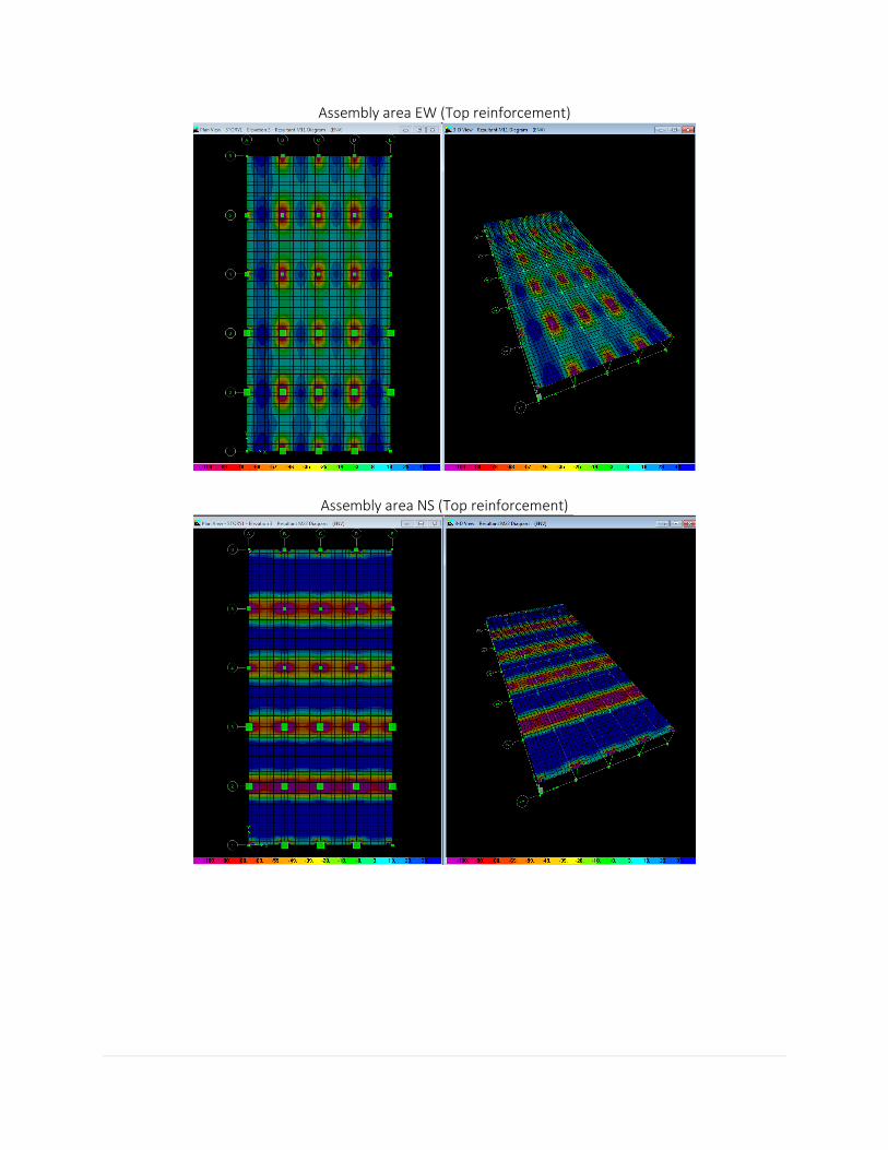
Assembly area EW (Top reinforcement)
Assembly area NS (Top reinforcement)

Sitting area EW (Bottom reinforcement)
Sitting area NS (Bottom reinforcement)

Sitting area EW (Top reinforcement)
Sitting area NS (Top reinforcement)

4.0 DOME: COLUMN REINFORCEMENT
Reinforcement of Dome Columns (Occupancy: Assembly) [14]
COLUMN SIZE 450X450 400X400 200X200 450X450
Column Location Edge Interior Edge Interior
e/h 0.721 0.046 0.543 0.068
Reinforcement
distribution 2 side 4 sides 2 sides 4 sides
Mf, kN∙m 139.43 18.66 16.79 13.02
Pf, kN 429.54 1010.97 154.68 423.34
e 324.603 18.458 108.547 30.755
γH 365 325 125 370
γ 0.811 0.813 0.625 0.822
Pf/Ag 2.121 6.319 3.867 2.091
Mf/Ag*h 1.530 0.292 2.099 0.143
ρt 0.010 0.010 0.010 0.010
K 593 610 528 661
As, mm2 2025 1600 400 2025
db 25 15 15 20
Ab, mm2 500 200 200 500
Number of rebars 6 8 4 6
Smin =max}
35 21 21 28
42 42 42 42
30 30 30 30
Smin, mm 42 42 42 42

Reinforcement of Dome Columns (Occupancy: Sitting area) [14]
COLUMN SIZE 300X300 850X850 850X850 800X800
Column Location Corner Interior Edge Interior
e/h 0.725 0.030 0.394 0.030
Reinforcement
distribution 2 sides 4 sides 2 sides 4 sides
Mf, kN∙m 44.09 15.04 203.07 32.23
Pf, kN 202.72 592.07 605.81 1364.88
e 0.22 25.40 335.20 23.61
γH 220 760 760 710
γ 0.733 0.894 0.894 0.888
Pf/Ag 2.252 0.819 0.838 2.133
Mf/Ag*h 1.633 0.024 0.331 0.063
ρt 0.010 0.010 0.010 0.010
K 610 661 593 661
As, mm2 900 7225 7225 6400
db 20 30 30 30
Ab, mm2 300 700 700 700
Number of rebars 3.000 10.321 10.321 9.143
Smin =max}
28 42 42 42
42 42 42 42
30 30 30 30
Smin, mm 42 42 42 42

5.0 DOME STAIRS DESIGN
Total span 4.74 m
//sum of 2*1.450 + 1.750
= 4.74 m
L= 4.74-0.5 = 4.24 m (clear span)
ts = L/20 0.21 m
rise = 0.20 m
run= 0.25 m
tanϴ= 0.80
ϴ = 38.66
Design procedure for flight of stairs
Average ts = ts + ((0.5*rise*run)/((rise2+ run2)0.5))
= 0.29 m
wlive= 7.20 kN/m
wdf landing = 11.14 kN/m //1.25* 0.29* 24/ cos(38.66)
wdf stairs = 8.15 kN/m
RB= 42.57 kN/m width of the slab
RA= 39.13 kN/m width of the slab
point of zero shear: V(x)= 0
X = 2.26 m
Mf max = 42.48
kN.m/m width of the
slab
Mf max = (7.20 + 8.15)*(4.74^2)/8 = 43 kN.m

5.1 Design of Stair Slab
d = ts - cover - db/2 = 177.00 mm
Mr=Mf max = 42.48 kN.m
b= 1000.00 mm
Kr = Mr/(bd^2)= 1.36
Based on Kr and Area Ratio Table, check for satisfaction of
min As ratio
Kr1= 0.90
Kr2= 1.36
Kr3= 1.30
Check if row > row-min
Assume b = 1000 mm
ρ1= 0.0027
//Using table 2.1 of CAA Concrete Design Handbook, obtain ratios of ρ with
Kr
ρ2= 0.00418147 // Interpolate between 0.9 and 1.3: (D42+((D44-D42)*((B43-B42)/(B44-B42))))
ρ3= 0.004
ρ= 0.00418147 > ρmin=0.002 OK
As min= ρbd = 740.12 mm^2
Try 20M @200 mm c/c:
20 M = 300 mm^2 200.00 mm
As = 1256 mm^2 > As min OK
Therefore, A = (20^2)*3.14/4 * 4 = 1256 mm^2 > 740.12,
place 4-20M at a spacing of 200 mm

Figure 1.A: ETABS Stair Model, Dead Load
*Figure 1.B: Stairs Bending Moment Diagram, Dead and Live Loads
*Figure 1.C: Stairs Analysis and Deformation
*ETABS Stairs Model was analyzed through the help and collaboration of Julien Egron, member of Team 4.

Flexure Design
try section L550x250 mm:
Beam width 250.00 mm
Height of Beam 550.00 mm
Height of Wall 3.60 m
Span Length (ln) 5 m
Weight of Wall 2.00 kPa
= 2.0*(hwall-hb)= 6.10 kN/m
beam weight= bw*(hb-ts)*24= 2.03 kN/m
wf = Ra + beam weight +wwall = 47.26 kN/m
V = (wf ln)/2 = 106.57 kN
Mf max= (wf ln^2)/8 = 120.16 kN.m
d = hb-40 510.00 mm
hf= ts = 212 mm
L1 4740 mm
b' (mm) = ln/12 = 0.375833333
6hf = 1272
(L1-bw)/2 = 2245
Units in mm
beff. = b'+bw = 250.38
mm
// calculate the effective beam
width
Kr = (Mr *10^6)/(beff.d^2) = 1.8451 // calculate Kr ratio
Kr1= 0.99 ρ1= 0.003
Kr2= 1.85 ρ2= 0.005655151
Kr3= 1.32 ρ3= 0.004
As min= ρbd =
722.12
mm^2
// A =
(0.0047)(250.38)(510.00) =
610.89 mm^2

Try 2-30M: 706.5 mm^2
As = 2*700 = 1400.00
mm^2 >
Asmin // Satisfies Area requirement
Check if As will fit in one layer:
Smin 1.4 db = 1.4*20 = 28
1.4 *(Concrete Unit
Weight, 25MPa) 35
30.00 30
use 10M bars for stirrups
Bmin = 2(cover) 2(dbs)+ 2(db)+
1(Smin) 175.00
<
bw=300
OK
// Bmin = 2*30 + 2*10 + 2*30
+35 = 175 mm
spacing = 140.00 mm
Clear for stirrups = 60 mm

6.0 RAINWATER COLLECTION SYSTEM
a) Rain Intensity
Method 1 (by average rainfall depth)
Rainfall Intensity Calculation
Month Rainfall
(mm)
Rainfall
(inches)
Snowfall (mm) Snowfall (inches)
January 28.4 1.118108 45.9 1.807083
February 22.7 0.893699 46.6 1.834642
March 42.2 1.661414 36.8 1.448816
April 65.2 2.566924 11.8 0.464566
May 86.1 3.389757 0.4 0.015748
June 87.5 3.444875 0 0
July 106.2 4.181094 0 0
August 100.6 3.960622 0 0
September 100.8 3.968496 0 0
October 82.1 3.232277 0 0
November 68.9 2.712593 2.2 0.086614
December 44.4 1.748028 24.9 0.980313
Wet Snow (inches) Total Precipitation
(inches)
0.1807083 1.2988163
0.1834642 1.0771632
0.1448816 1.8062956
0.0464566 2.6133806
0.0015748 3.3913318
0 3.444875
0 4.181094
0 3.960622
0 3.968496
0 3.232277
0.0086614 2.7212544
0.0980313 1.8460593
0.6637782 2.795138767 Average Monthly Intensity (in/month)
Table 1: Estimated Monthly Precipitation converted to RAINFALL

Notes
a. Data from Weather Network Statistics
b. Wet Snow = Snow depth (inches) / 10 , ratio of 1000 kg/m^3 / 160 kg/m^3
c. Average Monthly = sum ( Total Precipitation) / 12 = 2.795 in/month
d. Hourly Intensity = 2.795 in / month * 1 month/ 30 days * 1 day/ 24 hours =
0.00388 in/hour
Month
Rainfall
(mm)
Rainfall
(inches) Snowfall (mm)
January 47 1.85039 36
February 32 1.25984 39
March 32 1.25984 43
April 0 0 34
May 0 0 22
June 67 2.63779 0
July 64 2.51968 0
August 74 2.91338 0
September 82 3.22834 6
October 81 3.18897 21
November 94 3.70078 31
December 51 2.00787 41
Table 2: Maximum Montly Precipation converted to RAINFALL (Recorded)
Snowfall (inches) Wet Snow (inches)
Total
Precipitation
(inches)
1.41732 0.141732 1.992122
1.53543 0.153543 1.413383
1.69291 0.169291 1.429131
1.33858 0.133858 0.133858
0.86614 0.086614 0.086614
0 0 2.63779
0 0 2.51968
0 0 2.91338
0.23622 0.023622 3.251962
0.82677 0.082677 3.271647
1.22047 0.122047 3.822827
1.61417 0.161417 2.169287
Total Precipitation (inches/year) 25.641681
Total Precipitation (mm/year) 651.256
Table 2: Maximum Montly Precipation converted to RAINFALL (contd)

Sample Calculation
651.256 * year/12months * 1month/30 days *1day/24 hours = 0.075 mm/hour
*this does NOT take into account return period, or duration, and is not accurate for design
purposes involving rain intensity.
Rainfall Intensity Calculation: Method 2
This calculation is more accurate and is based on formulas obtained from “Sewage,
Distribution, Rainfall Analysis” by Francois Briere. It includes the return period, rainfall
duration, and specific equations related to rainfall intensities in Montreal.
Montreal Region
Return
Period 5 years 10 years
t (min)
Rainfall Intensity
(mm/h)
Rainfall Intensity
(mm/h)
Duration of
Rainfall 2184.4 / (t + 12) 2743.2 / (t + 14)
30 52.00952381 62.34545455
45 38.32280702 46.49491525
60 30.33888889 37.07027027
75 25.10804598 30.82247191
100 19.50357143 24.06315789
120 16.54848485 20.47164179
Montreal (Dorval
Airport)
Return
Period 5 years 10 years
t (min)
Rainfall Intensity
(mm/h)
Rainfall Intensity
(mm/h)
Duration of
Rainfall
1121.542 /(t +
7.507)^0.856
1562.794 / (t +
9.094)^0.892
30 50.3936005 59.39358202
45 37.78414629 44.45624129
60 30.47143884 35.73723564
75 25.66252706 29.99240872
100 20.46000285 23.77844021
120 17.67984341 20.46319919
Table 1B: Estimating Rainfall Intensity (Dorval)
For a 10 year, average duration of 60 min storm, the average rainfall intensity is 35.73 - 37.07 mm/h
This does not take into account SNOW
Using this intensity, use Rational Method: Qp = CiA to determine PEAK FLOW RATE.

b) Rational Method for Estimating Peak Flow Rate:
According to Wurbs and James, “Water Resources
Engineering”, the following formula is applicable to estimating
the peak flow rate of drainage and runoff areas, such as roofs,
parkings, roads, and grasslands:
Qp = CiA
C = 0.9 (based on rational constant table for roofs)
I = intensity, the maximum intensity is used in this case = 37.07 mm/h --> 37.07*0.1/2.54
= 1.46 in/hour
A = Area of drainage = Surface area of Dome: 653 m^2
Qp = 0.9*0.03707 m/hour * 653 * 1hour/3600 s = 0.00604 m^3/s
PEAK FLOW RATE (Qp) = 0.00604 m^3/s
Based on this estimation, the pipes must be able to provide a diameter large enough to accommodate
a flow rate
of 0.00604 m^3/s.
*Approved by Dr. Han, BCEE
Concordia University
c) Manning’s Equation for Open-Channel Flow
Design Assumptions
1 Open-Channel Flow
2 Pipe filled at 2/3 (d/D = 0.67)
3 Material Used: Corrugated STEEL, n design = 0.024
4 A = 2/3 Actual
Formulas Applicable:
1. Manning Equation: Q = 1/n * Rh^2/3 * So^1/2
2. Rh (partially filled pipe) = 0.25 * (a - sina)/a * D, where a = internal angle
3. internal angle (a) = 0.5* ( 1 - cos a/2) = d/D, a =219.753 degrees

A) Hardy-Cross Method to
Determine Flow Rate
Distribution
Assume: Flow rate of Qp = 0.0064 m^3/s
flows onto area of 653 m^2, into 10 vertical
pipes
Qi = Qp/10 = 0.0064
m^3/s / 10 = 0.00064
m^3/s
Assume: every flow rate entering from the exterior pipes divides into 50% left, 50% right
directions, therefore the MAXIMUM flow rate obtained is 2*0.000604 = 1.208*10^-3
m^3/s
Figure 1 : Partially Filled Pipe
d) Hardy-Cross Method
The assumption involves dividing the
pipe flow into 50% running from each
side, therefore the total flow in each
vertical pipe is estimated as
Q = 0.000604 m3/s, this flow rate will move down the vertical pipe and divide into 2 directions.
The important factor to consider in this case, is that a buffer time is included from the time the
flow reaches the dome to when it enters the pipe and flows down. This buffer time therefore acts
as a control or "lag", which considerable slows the velocity inside the pipe. Preliminary design
is drawn as follows:

Figure 2.1 : Sketch of Pipe System
Based on the mentioned design, 2 different pipe sizes will be needed: one for the vertical pipe
entrance, as well as the bends entering the underground system, and another at points A and
B of a larger size, entering the water tank at the intersection of the 3 pipes.
Design Equation by Trial & Error
The slopes in this case were designed by trial and error, based on best fit according to lengths of
pipes and heights of the dome and basement foundation.
For partially-filled pipes, the hydraulic radius is calculated using the following equation:
Rh (partially filled pipe) = 0.25 * (a - sina)/a * D
Where a is the internal angle illustrated between the arrows in figure 2, and D is the total pipe
diameter
The Manning’s equation is used to determine the design diameter, using 2/3 of the total area:
1/n *(0.25 * (1 - sin a)/a * D )2/3 * (So)0.5= Q / (2/3 * A)
Based on the steel piping alignment, and the overall dome structure, various slopes were tested by
trial and error for design. So1 was chosen as 3/7 and So2 was chosen as 1.5/7. These slopes were
determined according the height of the dome, the height of the vertical pipes, as well as the height
of the basement.
So1 =
3/7
1/0.024 *(0.25 * (1 - sin 219.75)/219.75 * D )^2/3 * (3/7)^0.5 = 2 * Q / (2/3 * pi D^2/4),
where Q = 0.001208 m^3/s , 2*0.000604 m^3/s
So2 =
1.5/7
1/0.024 *(0.25 * (1 - sin 219.75)/219.75 * D )^2/3 * (1.5/7)^0.5 = 2 * Q / (2/3 * pi
D^2/4), where Q = 0.001208 m^3/s , 2*0.000604 m^3/s

D1 0.143 m = 143.2 mm
D2 0.16346 m = 163.46 mm
Convert to inches: 163.46/10 *1/2.54 cm = 6.43 inches, use minimum required as 6 inches.
The minimum diameter needed is 8 inches. According to the Nominal Pipe Sizes of Table, use
either 8 in (8.625 outside diameter, or 6 in (6.75 outside diameter)
for optimal design. To be safe and economical, use a diameter of 6 inches , or 150 (15.32 cm)
mm.
A and B Convergence
Points A and B have 3 individual pipes merging into one large pipe, which will then transport the
rainwater into a water tank.
In order to accommodate for the flow rates entering the pipes, another pipe design calculation is
required.
The maximum Q possible according to the Hardy-Cross method is 2* 0.001208 + 0.000604 m^3/s
= 3.02*10^-3 m^3/s. This is based on the assumption that half the flow rates will enter each pipe,
where as the entire flow rate will pass through the pipes that are vertically connected to the dome.
New Design Equation by Trial & Error
(for large merging pipe at intersection)
So1 = 0.5/9 D1 =
1/0.024 *(0.25 * (1 - sin 219.75)/219.75 * D )^2/3 *
(0.5/9)^0.5 = Q / (2/3 * pi D^2/4), where
Q = 0.00302 m^3/s, D = 296.12mm
So2 = 0.0001(~ 0) D2 =
1/0.024 *(0.25 * (1 - sin 219.75)/219.75 * D )^2/3
* (0.0001)^0.5 = Q / (2/3 * pi D^2/4), where
Q = 0.00302 m^3/s, D = 123.8 mm
So3 = 0.85/9 D3 =
1/0.024 *(0.25 * (1 - sin 219.75)/219.75 * D )^2/3 *
(0.85/9)^0.5 = Q / (2/3 * pi D^2/4), where
where Q = 0.00302 m^3/s, D = 268.07 mm
*Design Equation developed by the help of Dr. Li
For optimal slope and design, use D = 255
mm, for a horizontal slope leading to tank. Conversion to inches: 26.8/2.54 = 10.55 inches
According to the nominal pipe sizes, a safe and economical design diameter is chosen as
10 (10.75 outer diameter) inches.

As displayed in figure 2.2, the flow
rate will increase three times the
initial flow rate, since 3 pipes will
merge into one larger pipe. This
connection illustrates the A and B
convergence system. As a result, a
larger diameter will be needed for
the pipe. According to the above
calculations, a pipe diameter of 10
inches has been used for optimal
design.
Figure 2.2: Pipe Convergence
Figure 2.3: Pipe Cross-Section Comparisons

Table 3 : Nominal Pipe Sizes, Steel
Nominal
Size
Outside
Diameter
Thick
ness
Inches Inches mm inches mm
2 and 1/2 2.875
73.7179
487 0.203 5.205128205
3 3.5
89.7435
897 0.216 5.538461538
5 5.563
142.641
026 0.258 6.615384615
6 6.625
169.871
795 0.28 6.345
10 10.75
275.641
026 0.365 10.385
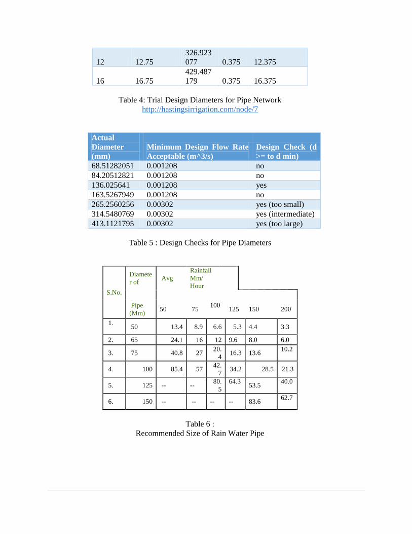
12 12.75
326.923
077 0.375 12.375
16 16.75
429.487
179 0.375 16.375
Table 4: Trial Design Diameters for Pipe Network
http://hastingsirrigation.com/node/7
Actual
Diameter
(mm)
Minimum Design Flow Rate
Acceptable (m^3/s)
Design Check (d
>= to d min)
68.51282051 0.001208 no
84.20512821 0.001208 no
136.025641 0.001208 yes
163.5267949 0.001208 no
265.2560256 0.00302 yes (too small)
314.5480769 0.00302 yes (intermediate)
413.1121795 0.00302 yes (too large)
Table 5 : Design Checks for Pipe Diameters
S.No.
Diamete
r of Avg
Rainfall
Mm/
Hour
Pipe
(Mm) 50 75
100
125 150 200
1.
50 13.4 8.9 6.6 5.3 4.4 3.3
2. 65 24.1 16 12 9.6 8.0 6.0
3. 75 40.8 27 20.
4 16.3 13.6
10.2
4. 100 85.4 57 42.
7 34.2 28.5 21.3
5. 125 -- -- 80.
5
64.3
53.5
40.0
6. 150 -- -- -- -- 83.6 62.7
Table 6 :
Recommended Size of Rain Water Pipe

Figure 4.1 : Steel Pipes
Figure 4.2 : Steel Gutter and Bracket (drawn using AutoCAD)
According to figure 4.2, the steel brackets and gutters have been designed according to
nominal gutter and bracket sizes. The following AutoCAD drawing displays the diameter of
250 mm, which is the optimal measurement able to connect a pipe diameter of 200 mm,
which is the size of the vertical pipes connected to the gutter system.

Figure 5 : Steel Gutter System
Figure 6: Pipe Fittings Examples

Half-round gutter bracket, NFH, load rating: H
N. parts produced Nominal size Length Material
10 200x25x4 230 TECU® Classic
galvanized steel
8 250x25x4 280 TECU® Classic
galvanized steel
7 280x30x4 290 TECU® Classic
galvanized steel
7 280x30x5 290 TECU® Classic
6 333x30x5 300 TECU® Classic
galvanized steel
6 333x40x5 300 TECU® Classic
5 400x30x5 340 TECU® Classic
Table 6.1: Bracket Design Sizes
Figure 7: Welded Pipe Fittings

Volume of Water Tank
Maximum Q = 2*0.00302 = 0.00604 m^3/s * 3600s/1h = 21.7 m^3
(This is the volume of water collected after a 60 min storm)
21 m^3 * 1gal/3.78 L * 1 L / 10^-3 L = 5752.4 gph = 95.8 gpm
Choose a suitable tank size from construction industry:
Since the minimum volume needed is 22 m^3, choose a design of
4m width, 2 m height, and 3 m wide rectangular water tank (iron
plates), Volume Capacity = 4*2*3 = 24 m^3
Water Tank
Material: Galvanized Steel, volume of 24 m^3
Tant considerations (adapted from the National Environmental Health Forum, Guidance on the
use of Water Tanks)
Inlet to tank will have a mesh covering to prevent mosquitos/insects/debris/leaves from
entering
Since tank is underground, it will ensure that no light will penetrate the water tank, to
prevent growth of algae (which affects health, odour, colour, and taste of water)
Both 10-inch pipe entrances will include a water filter
Figure 3: Galvanized Steel Water Tank
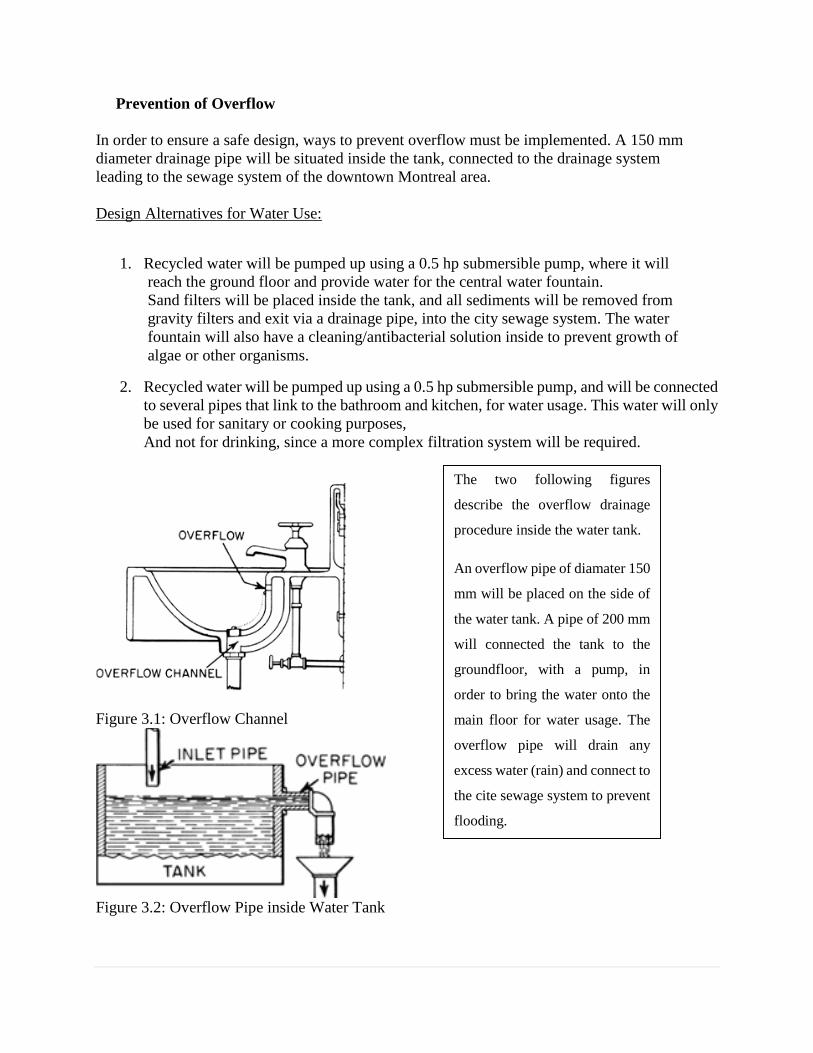
Prevention of Overflow
In order to ensure a safe design, ways to prevent overflow must be implemented. A 150 mm
diameter drainage pipe will be situated inside the tank, connected to the drainage system
leading to the sewage system of the downtown Montreal area.
Design Alternatives for Water Use:
1. Recycled water will be pumped up using a 0.5 hp submersible pump, where it will
reach the ground floor and provide water for the central water fountain.
Sand filters will be placed inside the tank, and all sediments will be removed from
gravity filters and exit via a drainage pipe, into the city sewage system. The water
fountain will also have a cleaning/antibacterial solution inside to prevent growth of
algae or other organisms.
2. Recycled water will be pumped up using a 0.5 hp submersible pump, and will be connected
to several pipes that link to the bathroom and kitchen, for water usage. This water will only
be used for sanitary or cooking purposes,
And not for drinking, since a more complex filtration system will be required.
Figure 3.1: Overflow Channel
Figure 3.2: Overflow Pipe inside Water Tank
The two following figures
describe the overflow drainage
procedure inside the water tank.
An overflow pipe of diamater 150
mm will be placed on the side of
the water tank. A pipe of 200 mm
will connected the tank to the
groundfloor, with a pump, in
order to bring the water onto the
main floor for water usage. The
overflow pipe will drain any
excess water (rain) and connect to
the cite sewage system to prevent
flooding.

Energy Losses in Pipes
* All friction values and formulas were obtained from Water Resources Engineering, Wurbs
and James, in the section Hydraulic Pipes.
Major Losses: hL = f*L/D* Q^2 / A^2 * 1/ 2g
Minor Losses: hL = K* (Q/A)^2 * 1/2g
Material e (mm) e (inches)
Concrete 0.3 - 3.0 0.012 - 0.12
Cast Iron 0.26 0.010
Galvanized Iron 0.15 0.006
Asphalted Cast Iron 0.12 0.0048
Commercial or Welded Steel 0.045 0.0018
PVC, Glass, Other Drawn Tubing 0.0015 0.00006
Table 7: Relative Roughness for Pipes of Different Material
Figure 3.3: Friction Factor for Energy Losses in Pipes

According to figure 3.3, a relative roughness of 2.25*10^-4 and a Reynolds number of 1.08*10^6
will result in a friction factor of roughly 0.015.
Between sections 1 and 2, convert potential energy to kinetic energy: mgh = 0.5 mv2,
v = (2*gh) 0.5
With a height of 1.5 m,(1.5*9.81*2)^0.5 = 5.4 m/s
The velocity according to complete conversion of potential energy to kinetic energy, neglecting
the buffer time, is 5.4 m/s.
Since this velocity does not take into account the buffer time, or energy loss, it can be assumed
to fit the range of 1-3.5 m/s after subtraction of time and
losses.
To calculate the energy loss, the pipe is a 90 degree curved pipe, having a K value of 0.1, length
of 7 m
Minor Head Loss = k.v^2/2g = 0.1*5.4^2/2g = 0.148 m
f is obtained from the Moody diagram, knowing the roughness of the pipe and the Reynold's
number, Re.
Reynold's Number:
Re = VD/v = 5.4*0.2/(1*10^-6 m^2/s) at 20 degrees Celsius
Re = 1.08 * 10^6 ---> TURBULENT FLOW
Relative Roughness (e/D) = 0.045/200 m = 0.000225
f according to table = 0.015
Major Head Loss = f*(L/D)(V^2/2g) = 0.015*(7/0.2)*(5.4^2)/(2*9.81) = 0.78 m
For the pipes located on the opposite corner, parallel to the circular dome, the energy conversion
becomes:
Slope is 0.85/9m
V = (2*0.85*9.81)^0.5 = 4 m/s
Again, the velocity does not include buffer time or frictional losses, and therefore the velocity
is much lower than calculated.

Minor Head Loss = 0.1*4^2/2g = 0.0815 m
Major Head Loss = 0.015*(4^2/2g)*(9/0.2) = 0.55 m
Note:
In terms of design, since the flow rate is very low based on the Rational Method, the frictional
and energy losses will be minimized.
As a result, the losses were calculated with the velocities obtained from energy conservation.
Although this is an approximate method
to estimate the losses, the conclusion is that the velocity is low enough to not cause high
frictional losses, since the diameter of the pipes is fairly large.
Pump Requirements
Table 7: Theoretical Pumping Power Required for Head (ft.)

7.0 COMPLETE QUANTITY TAKE-OFF
CSI Item
Code Item Description
Takeoff
Qty Unit
Labor
$/Unit
Mat
$/Unit
Mat
Quantity
Mat
Conversion
Mat
Price
Mat
Unit
Subs Unit
Price
Total
$/Unit Grand Total
Dome 1,078,586.01
2000 – Site work
2800 - Site
Improvements**
2820 - Fountains
10 Central 7m x 7m Fountain System 1 lsum 50,000.00 50,000.00 50,000.00
Fountains Total 50,000.00
Site Improvements** Total 50,000.00
2900 - Landscaping **
2950 - Trees Plants and
Ground Covers
180 Indoor Trees - 20' 6 each each 660.87 950 5,700.00
Trees Plants and Ground Covers
Total
5,700.00
Landscaping ** Total 5,700.00
Site work Total 55,700.00
3000 - Concrete
3200 - Concrete
Reinforcement
3201 - WireMesh **
50 Wire Mesh 4x4 4/4 8,323.70 sqft 9,156.07 0.3 0.3 2,497.11
100 Installation of Wire Mesh 7,567.00 sqft 0.1 0.1 756.7
WireMesh ** Total 3,253.81
Concrete Reinforcement Total 3,253.81
3300 - Cast In Place
Concrete
3301 - BCI Concrete
Supply **
1 Environmental Cost 240.6 cy 2.49 184.03 0.765 3.25 M3 2.49 598.08
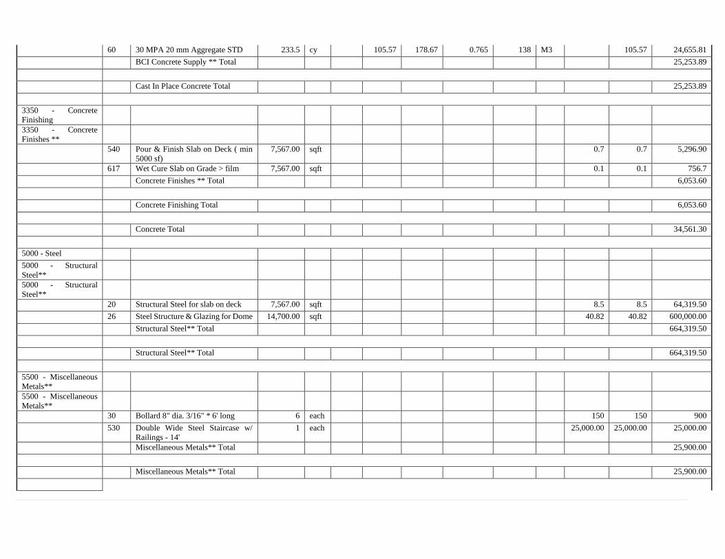
60 30 MPA 20 mm Aggregate STD 233.5 cy 105.57 178.67 0.765 138 M3 105.57 24,655.81
BCI Concrete Supply ** Total 25,253.89
Cast In Place Concrete Total 25,253.89
3350 - Concrete
Finishing
3350 - Concrete
Finishes **
540 Pour & Finish Slab on Deck ( min
5000 sf)
7,567.00 sqft 0.7 0.7 5,296.90
617 Wet Cure Slab on Grade > film 7,567.00 sqft 0.1 0.1 756.7
Concrete Finishes ** Total 6,053.60
Concrete Finishing Total 6,053.60
Concrete Total 34,561.30
5000 - Steel
5000 - Structural
Steel**
5000 - Structural
Steel**
20 Structural Steel for slab on deck 7,567.00 sqft 8.5 8.5 64,319.50
26 Steel Structure & Glazing for Dome 14,700.00 sqft 40.82 40.82 600,000.00
Structural Steel** Total 664,319.50
Structural Steel** Total 664,319.50
5500 - Miscellaneous
Metals**
5500 - Miscellaneous
Metals**
30 Bollard 8" dia. 3/16" * 6' long 6 each 150 150 900
530 Double Wide Steel Staircase w/
Railings - 14'
1 each 25,000.00 25,000.00 25,000.00
Miscellaneous Metals** Total 25,900.00
Miscellaneous Metals** Total 25,900.00

Steel Total 90,219.50
6000 - Wood and
Plastics
6140 - Rough
Carpentry Labor **
6140 - Rough Carp
Labor **
125 Carpenter Blocking Toilet Access 26 each 32.5 32.5 845
150 2 Carpenters to Install Plywood
(4x8)
578 sqft 2.5 2.5 1,445.00
Rough Carp Labor ** Total 2,290.00
6145 - Misc
Installation **
100 Install Toilet Accessories 26 each 75 75 1,949.92
Misc Installation ** Total 1,949.92
Rough Carpentry Labor ** Total 4,239.92
6150 - Rough
Carpentry Material **
6153 - Plywood
130 3/4" Standard Ply 4'x8' 636 sqft 0.93 21.86 0.031 27 ea 0.93 590.29
Plywood Total 590.29
Rough Carpentry Material ** Total 590.29
6200 - Finish
Carpentry**
6219 - Millwork**
20 Reception Desk Allowance 2 each 5,000.00 2 5,000.00 each 5,000.00 10,000.00
240 Melamine Counter & Cupboards 55 lnft 150 150 8,250.00
270 Standard Commercial Vanity 24 lnft 150 150 3,600.00
Millwork** Total 21,850.00
Finish Carpentry** Total 21,850.00
Wood and Plastics Total 26,680.21

8000 - Doors and
Windows
8800 - Glazing **
8800 - Glazing **
130 Mirror 96 sqft 20 20 1,920.00
Glazing ** Total 1,920.00
Glazing ** Total 1,920.00
Doors and Windows Total 1,920.00
9000 - Finishes
9300 - Tile
9310 - Ceramic Tile
160 Ceramic Tile - Standard Grade 5,575.00 sqft 5 5 27,875.00
210 Ceramic Tile Base 4" Thin Set 300 lnft 1.5 1.5 450
250 Ceramic Tile Base Installation 300 lnft 4 4 1,200.00
400 Ceramic Floor Tile Installation 5,575.00 sqft 4 4 22,300.00
Ceramic Tile Total 51,825.00
Tile Total 51,825.00
Finishes Total 51,825.00
10000 - Specialties
10150 - Compartments
and Cubicles
10150 - Toilet
Partitions/Urinal
Screens **
220 Toilet Partitions - Plam - Floor
Mount
6 each 690 690 4,140.00
310 Urinal Screens Plastic laminate
Wall Hung
2 each 450 450 900
Toilet Partitions/Urinal Screens **
Total
5,040.00
Compartments and Cubicles Total 5,040.00

10800 - Toilet and
Bath Accessories **
10800 - Toilet
accessories **
3000 Toilet Paper Dispensers Multi Roll 6 each 35 35 210
3010 Soap Dispenser Liquid Surface
Mntd
5 each 130 130 650
3020 Towel Dispensers w/Waste
Receptacle
2 each 500 500 1,000.00
3030 Pair Grab Bars Handicap 2 each 90 90 180
3040 Feminine Napkin Disposal 4 each 150 150 600
3050 Baby Change Table 2 each 500 500 1,000.00
3070 Mirrors - Stainless Steel Frame 24"
x 36"
5 each 270 270 1,350.00
Toilet accessories ** Total 4,990.00
Toilet and Bath Accessories **
Total
4,990.00
10900 - Miscellaneous
Specialties
10900 - Miscellaneous
Specialties
220 Interior Benches 6 each 700 700 4,200.00
Miscellaneous Specialties Total 4,200.00
Miscellaneous Specialties Total 4,200.00
Specialties Total 14,230.00
12000 - Furnishings
12800 - Office
Furnishings
12800 - Office
Furnishings
50 Waiting Area Chair 6 each each 250 250 1,500.00
50 Waiting Area Couch 3 each each 600 600 1,800.00
50 Dining Table -12 People 3 each each 300 300 900
50 Renovation of Kitchen Equipment 1 each each 10,000.00 10,000.00 10,000.00
Office Furnishings Total 14,200.00

Office Furnishings Total 14,200.00
Furnishings Total 14,200.00
15000 - Mechanical
15000 - Mechanical
5051 - Basic
Mechanical Materials
9010 Mechanical, Electrical, Sprinklers
& Pumbing Allowance for Dome
7,570.00 sqft 25 25 189,250.00
Mechanical Total 189,250.00
10 Dome 1,078,586.01
Main Structure 9,130,284.53
2000 - Sitework
2221 - Pavement
Sitework **
02221 - Pavement
Sitework **
120 Pavement Infra 0-20 mm 623.4 cy 40.5 1,122.17 1.8 22.5 mton 22.5 63 39,276.07
130 Pavement Backfill 0-56 mm 1,246.90 cy 38.88 2,244.35 1.8 21.6 mton 21.6 60.48 75,410.05
170 Regrade, Recompact & + Min 3,740.60 sy 1.5 1.5 5,610.87
350 105mm Asphalt (MTL, 3-River,
Que)
3,740.60 sy 25 1,103.89 0.295 84.71 mton 25 93,514.45
380 Final Grade Stone - Asphalt HD 3,740.60 sy 1.5 1.5 5,610.87
430 Geotextile membrane 3,740.60 sy 1.25 1.25 4,675.72
Pavement Sitework ** Total 224,098.03
Pavement Sitework ** Total 224,098.03
2222 - Hard
Landscaping **
02222 - Hard
Landscaping **
30 Cast in Place Concrete Curbs 1,191.30 lnft 16 16 19,061.12
120 Infrastructure for Hard
Landscaping
36.5 cuyd 65.73 1.8 mton 22.5 22.5 821.65
140 Concrete sidewalk 1,972.00 sf 7.5 7.5 14,789.77
Hard Landscaping ** Total 34,672.55

Hard Landscaping ** Total 34,672.55
2900 - Landscaping **
2900 - Landscaping
130 Sodded Areas w/ Topsoil 2,083.40 sy 6 6 12,500.52
Landscaping Total 12,500.52
2950 - Trees Plants and
Ground Covers
180 Interior Decorative Planter 12 each each 500 543.75 6,525.00
180 Outdoor Trees - 20' 10 each each 660.87 950 9,500.00
180 Outdoor Shrubs 2' 40 each each 92.59 125 5,000.00
Trees Plants and Ground Covers
Total
21,025.00
Landscaping ** Total 33,525.52
Sitework Total 292,296.09
2050 - Demolition
2050 - Demolition **
02050 - Demolition
30 Demolish Existing Elevator - 5
Stops
1 each 3,000.00 3,000.00
45 Demolition of Slab on Grade 10,907.50 sqft 5 5 54,537.40
45 Demolition of Steel Structure 30' &
Roofing
10,907.50 sqft 2.5 2.5 27,268.70
45 Demolition of Existing Slab sqft 1.5 1.5
45 Demolition of Concrete Slab 8,876.00 sqft 5 5 44,379.95
45 Demolition of Existing Wood Slab 97,000.00 sqft 1.5 1.5 145,500.00
45 Demolition of Steel Deck 10,907.50 sqft 1 1 10,907.48
55 Sawcutting Concrete Slab 133.7 lnft 2 2 267.44
200 Demolish Interior Block Wall 4,389.10 sf 2 2 8,778.11
200 Demolish Interior Partition 22,855.80 sf 2 2 45,711.70
200 Demolish Exterior Brick Wall &
Backup 30'
13,731.70 sf 5 68,658.33
200 Demolish Interior Partition 59,039.70 sf 2 2 118,079.47
200 Demolish Furring Partition 43,800.80 sf 1.5 1.5 65,701.24
200 Demolish Interior Partition 7,215.70 sf 2 2 14,431.31

200 Demolish Furring Partition 3,243.10 sf 1.5 1.5 4,864.64
200 Remove and Recuperate Exterior
Stone
2,000.00 sf 5 5 10,000.00
225 Remove Single Door/Frame 381 each 40 40 15,240.00
Remove Existing Ceilings 119,781.50 sf 2 2 239,563.04
350 Remove Existing Floor Finishes 120,976.20 sf 1.75 1.75 211,708.26
375 Remove counters/millwork 1,764.00 lf 1.5 1.5 2,646.02
530 Demolish Wood Stairs, 5 Floors,
65' h
1 each 2,000.00 2,000.00 2,000.00
600 Remove RTU 6 each 1,000.00 1,000.00 6,000.00
Demolition - BCI Total 1,099,243.09
Demolition ** Total 1,099,243.09
Demolition Total 1,099,243.09
3000 - Concrete
3200 - Concrete
Reinforcement
3201 - WireMesh **
50 Wire Mesh 4x4 4/4 100,401.80 sqft 110,442 0.3 0.3 30,120.55
100 Installation of Wire Mesh 91,274.40 sqft 0.1 0.1 9,127.44
WireMesh ** Total 39,247.98
Concrete Reinforcement Total 39,247.98
3300 - Cast In Place
Concrete
3301 - BCI Concrete
Supply **
1 Environmental Cost 1,015.60 cy 2.49 776.91 0.765 3.25 M3 2.49 2,524.96
60 30 MPA 20 mm Aggregate STD 986 cy 105.57 754.28 0.765 138 M3 105.57 104,090.83
BCI Concrete Supply ** Total 106,615.79
Cast In Place Concrete Total 106,615.79
3350 - Concrete
Finishing
3350 - Concrete
Finishes **

540 Pour & Finish Slab on Deck ( min
5000 sf)
91,274.40 sqft 0.7 0.7 63,892.07
617 Wet Cure Slab on Grade > film 91,274.40 sqft 0.1 0.1 9,127.44
Concrete Finishes ** Total 73,019.51
3355 - Concrete
Curing
900 Concrete Sealer 4,409.60 sqft 0.12 0.28 33.07 0.007 36.68 gal 0.4 1,763.83
Concrete Curing Total 1,763.83
Concrete Finishing Total 74,783.34
Concrete Total 220,647.11
4000 - Masonry
4100 - Masonry
Accessories **
4165 - Reinforcement
& Ties **
260 Masonry Reinforcing @ 24" 6,736.60 sqft 1.8 1.8 12,125.90
Reinforcement & Ties ** Total 12,125.90
4170 - Masonry
Sealants **
100 Fire rated Sealant 419.2 lnft 1 1 419.17
Masonry Sealants ** Total 419.17
Masonry Accessories ** Total 12,545.06
4200 - Unit Masonry
**
4202 - Standard Block
**
110 Standard Block 6" 1,601.00 sf 1,857.18 1.16 ea 14 14 22,414.18
190 Fire-rated Block 8" - 1 hrs Fire
Rating
6,736.60 sf 7,814.47 1.16 ea 16 16 107,785.75
Standard Block ** Total 130,199.93
Unit Masonry ** Total 130,199.93

Masonry Total 142,745.00
5000 - Steel
5000 - Structural
Steel**
5000 - Structural
Steel**
20 Structural Steel for slab on deck 91,274.40 sqft 8.5 8.5 775,832.26
10 Steel Column Reinforcement 450 each 2,000.00 2,000.00 900,000.00
Structural Steel** Total 1,675,832.26
Structural Steel** Total 1,675,832.26
5500 - Miscellaneous
Metals**
5500 - Miscellaneous
Metals**
30 Bollard 8" dia. 3/16" * 6' long 14 each 150 150 2,100.00
30 Elevator Pit Ladder 3 each 130 300 430 1,290.00
30 Painting & Repair of 4 Storey
Exterior Glav. Emergency Stairs
2 each 4,000.00 4,000.00 8,000.00
530 Steel Ext. Fire Escape - 5 Stories,
53' w/ Railings
1 each 4,000.00 4,000.00 4,000.00
530 Steel Staircase - 5 Stories, 53' w/
Railings
2 each 20,000.00 20,000.00 40,000.00
560 Interior Guard Rail 175.9 lnft 80 80 14,075.46
665 Elevator hoist beam 10 each 300 300 3,000.00
675 Elevator divider beam 4 each 200 200 800
705 Loose Lintel Single x 4' 22 each 150 150 3,300.00
Miscellaneous Metals** Total 76,565.46
Miscellaneous Metals** Total 76,565.46
Steel Total 1,752,397.72
6000 - Wood and
Plastics
6140 - Rough
Carpentry Labor **

6140 - Rough Carp
Labor **
10 Carp-Blueskin Application 2/Hr 22 each 32.5 32.5 715
125 Carpenter Blocking Toilet Access 344 each 32.5 32.5 11,180.00
140 2 Carpenters to install 2x4/2x6 440 lnft 2.5 2.5 1,100.00
150 2 Carpenters to Install Plywood
(4x8)
6,342.20 sqft 2.5 2.5 15,855.47
Rough Carp Labor ** Total 28,850.47
6145 - Misc
Installation **
100 Install Toilet Accessories 344 each 75 75 25,798.97
Misc Installation ** Total 25,798.97
Rough Carpentry Labor ** Total 54,649.43
6150 - Rough
Carpentry Material **
6151 - Lumber 2x
215 2 x 6 x 12' STD 440 lnft 0.49 0.48 0.001 445 mbft 0.49 215.38
Lumber 2x Total 215.38
6153 - Plywood
130 3/4" Standard Ply 4'x8' 7,100.20 sqft 0.93 244.07 0.031 27 ea 0.93 6,589.86
Plywood Total 6,589.86
6155 - Insulation &
Membranes
400 Primer for Blueskin Membrane 440 lnft 0.1 0.57 0.001 80 ea 0.1 45.3
410 Blueskin Membrane Roll 12" 440 lnft 0.88 6.44 0.013 60 ea 0.88 386.23
Insulation & Membranes Total 431.53
Rough Carpentry Material ** Total 7,236.78
6200 - Finish
Carpentry**
6219 - Millwork**
20 Upgrade Reception Desk
Allowance
1 each 15,000 1 15,000.00 each 15,000.00 15,000.00
240 Melamine Counter & Cupboards 498.5 lnft 150 150 74,770.27
270 Standard Commercial Vanity 178.1 lnft 150 150 26,716.46

Millwork** Total 116,486.73
Finish Carpentry** Total 116,486.73
Wood and Plastics Total 178,372.94
7000 - Thermal and
Moisture Protection
7200 - Insulation
7200 - Insulation
580 3" Sprayed Urethane 74,918.70 sqft 3 3 224,756.25
Insulation Total 224,756.25
Insulation Total 224,756.25
7250 - Fireproofing
7250 - Fireproofing
9000 Fireproof Structural Steel
Framing/Deck
91,274.40 sqft 2.5 2.5 228,185.96
Fireproofing Total 228,185.96
Fireproofing Total 228,185.96
Thermal and Moisture Protection
Total
452,942.21
8000 - Doors and
Windows
8100 - Metal Doors
8110 - Hollow Metal
Doors **
10 Install Insulated Metal Doors 22 each 175 175 3,850.00
15 Install FR Metal Doors 32 each 150 150 4,800.00
180 Insulated Metal Door - 3-0 x 7-0 22 each 275 275 6,050.00
280 FR Metal Door - 3-0 x 7-0 32 each 275 275 8,800.00
Hollow Metal Doors ** Total 23,500.00
8120 - Hollow Metal
Frames **

25 Install Metal Frames in Block 22 each 175 175 3,850.00
140 Hollow Metal Frame - 3-0 x 7-0 44 each 120 120 5,280.00
180 Hollow Metal Frame - 6-0 x 7-0 5 each 200 200 1,000.00
240 FR Metal Frame - 3-0 x 7-0 32 each 150 150 4,800.00
340 Insulated Metal Frame - 3-0 x 7-0 22 each 200 200 4,400.00
Hollow Metal Frames ** Total 19,330.00
Metal Doors Total 42,830.00
8200 - Wood Doors
8201 - Wood Doors **
50 Install Wood Door Pre-Machined 54 each 150 150 8,100.00
260 Hollow Core Masonite - 3-0 x 7-0 54 each 125 125 6,750.00
Wood Doors ** Total 14,850.00
Wood Doors Total 14,850.00
8400 - Entrances and
Storefronts
8400 - Entrances and
Storefronts
100 All Glass Entrance Doors 99 each 1,000.00 1,000.00 99,000.00
120 Revolving Doors 2 each 30,000.00 30,000.00 60,000.00
310 Aluminum Entrance Door 4 ea 1,000.00 1,000.00 4,000.00
350 Handicap Door Operators 2 each 2,500.00 2,500.00 5,000.00
400 Interior Vestibule 572.6 sqft 35 35 20,041.20
420 Aluminum Entrance Door 2 each 1,000.00 1,000.00 2,000.00
Entrances and Storefronts Total 190,041.20
Entrances and Storefronts Total 190,041.20
8700 - Hardware
8710 - Hanging
Hardware
20 Butt Hinge set - Steel - Std Duty 108 each 40 40 4,320.00
Hanging Hardware Total 4,320.00
8720 - Latching
Hardware

140 Lockset - Entrance Lock - Medium
Duty
108 each Each 80 80 8,640.00
Latching Hardware Total 8,640.00
8730 - Controlling
Hardware
210 Door Closer - Reg Parallel Arm -
Medium Duty
108 each each 210 210 22,680.00
Controlling Hardware Total 22,680.00
8740 -
Weatherstripping and
Seals
115 Threshold - 3' x 6" Wide Ext Alum
Thermal Break
22 each 50 50 1,100.00
Weatherstripping and Seals Total 1,100.00
Hardware Total 36,740.00
8800 - Glazing **
8800 - Glazing **
100 Single Glazing Tempered 6.9 sqft 9 9 62.5
100 Glass for Guard Rail in Lobby 616 sqft 20 20 12,320.00
100 Single Glazing Tempered 12.5 sqft 9 9 112.5
200 Int Glazed Wall w/ Silicone joints 11,885.40 sqft 20 20 237,707.66
220 Privacy film for glazed wall 7,436.70 sqft 8 8 59,493.44
Glazing ** Total 309,696.10
Glazing ** Total 309,696.10
Doors and Windows Total 594,157.30
9000 - Finishes
9250 - Drywall
9251 - Drywall
Framing
90 Bulkhead Bracing 1,039.50 each 5 5 5,197.69
95 Bulkhead Framing 18,392.50 sqft 2 2 36,784.92
110 Metal Studs Galv - 25 ga 1-5/8" 59,461.90 sqft 1.5 1.5 89,192.82

115 Metal Studs Galv - 25 ga 2-1/2" 15,865.30 sqft 1.6 1.6 25,384.40
155 Metal Studs Galv - 25 ga 3-5/8" 46,998.30 sqft 1.75 1.75 82,247.00
Drywall Framing Total 238,806.83
9252 - Gypsum
Wallboard
80 Drywall - Standard 1/2" on Walls 93,968.80 sqft 0.32 0.32 30,070.01
90 Drywall - Standard 1/2" on Ceilings 15,150.00 sqft 0.3 0.3 4,545.01
125 Drywall - Std 5/8" on bulkhead 5,108.70 sqft 0.32 0.32 1,634.77
170 Drywall - Fire Resist. 5/8" on Walls 53,521.30 sqft 0.32 0.32 17,126.83
230 Drywall - Moisture Resistant 5/8"
on Walls
10,555.60 sqft 0.35 0.35 3,694.45
400 Install Bulkhead Gypse 5,108.70 sqft 1 1 5,108.66
420 Install Interior Gypse to walls 166,989.60 sqft 0.75 0.75 125,242.17
600 Drywall Tape 15,420.30 sqft 0.75 0.75 11,565.21
Gypsum Wallboard Total 198,987.11
9260 - Drywall Finish
55 Joints/Finish Drywall 154,343.70 sqft 0.7 0.7 108,040.62
60 Joints/Finish @ Bulkhead 4,899.60 sqft 1 1 4,899.64
360 Fire rated Sealant 4,626.40 lnft 1 1 4,626.37
365 Acoustic Sealant Caulking 4,430.10 lnft 1 1 4,430.13
Drywall Finish Total 121,996.77
9270 - Insulation in
Drywall Systems
210 Acoustic Insulation - 3 5/8" 46,998.30 sqft 2.5 2.5 117,495.72
Insulation in Drywall Systems
Total
117,495.72
Drywall Total 677,286.43
9300 - Tile
9310 - Ceramic Tile
160 Ceramic Tile - Standard Grade 4,290.60 sqft 5 5 21,453.03
210 Ceramic Tile Base 4" Thin Set 923.7 lnft 1.5 1.5 1,385.55
250 Ceramic Tile Base Installation 923.7 lnft 4 4 3,694.81
320 Ceramic Wall Tile - Standard
Grade
4,654.80 sqft 5 5 23,273.85

400 Ceramic Floor Tile Installation 4,290.60 sqft 4 4 17,162.42
410 Ceramic Wall Tile Installation 4,654.80 sqft 4 4 18,619.08
Ceramic Tile Total 85,588.75
Tile Total 85,588.75
9500 - Acoustical
Treatment
9506 - Acoustical
Ceiling Tiles
20 Ceiling Tiles - 2x2 - Standard 98,964.90 sqft 2.5 2.5 247,412.29
Acoustical Ceiling Tiles Total 247,412.29
Acoustical Treatment Total 247,412.29
9550 - Wood Flooring
9550 - Wood Flooring
430 Maple Hardwood Flooring 4,309.40 sqft 10 10 43,094.29
510 Maple Hardwood Base 913.1 lnft 6 6 5,478.58
Wood Flooring Total 48,572.87
Wood Flooring Total 48,572.87
9600 - Stone Flooring
9600 - Stone Flooring
210 Granite Tile Base 6" 256.2 lnft 10 10 2,562.33
Stone Flooring Total 2,562.33
9620 - Granite
Flooring
20 Granite Flooring in Lobby 2,445.60 sqft 20 20 48,912.97
Granite Flooring Total 48,912.97
Stone Flooring Total 51,475.30
9650 -
Resilient Flooring
9650 - Resilient
Flooring

430 Vinyl Composition Tile - 1/8" - Std 15,489.70 sqft 2 2 30,979.44
510 Rubber Base - 4" 2,025.60 lnft 1.5 1.5 3,038.39
Resilient Flooring Total 34,017.83
Resilient Flooring Total 34,017.83
9680 - Carpet
9680 - Carpet
20 Roll Carpet 9,578.60 sqyd 30 30 287,358.21
160 Extra Cost for Pattern in Carpet 9,578.60 sqyd 2 2 19,157.20
300 Carpet Base Standard 9,968.20 lnft 1.5 1.5 14,952.28
Carpet Total 321,467.69
Carpet Total 321,467.69
9900 - Painting
9900 - Painting
600 Paint Drywall 154,588.60 sqft 0.6 0.6 92,753.17
620 Paint Block Wall 3,202.00 sqft 0.6 0.6 1,921.22
710 Paint Door & Frame 108 each 100 100 10,800.00
Painting Total 105,474.39
Painting Total 105,474.39
Finishes Total 1,571,295.54
10000 - Specialties
10050 - Footgrills **
10050 - Footgrills **
110 Footgrill - 4 x 6' 12 each 1,000.00 1,000.00 12,000.00
Footgrills ** Total 12,000.00
Footgrills ** Total 12,000.00
10150 - Compartments
and Cubicles

10150 - Toilet
Partitions/Urinal
Screens **
220 Toilet Partitions - Floor Mounted
Plastic Laminate
14 each 690 690 9,660.00
220 Toilet Partitions - Plam - Floor
Mount
49 each 690 690 33,810.00
310 Urinal Screens Plastic laminate
Wall Hung
22 each 450 450 9,900.00
Toilet Partitions/Urinal Screens **
Total
53,370.00
Compartments and Cubicles Total 53,370.00
10800 - Toilet and
Bath Accessories **
10800 - Toilet
accessories **
3000 Toilet Paper Dispensers Multi Roll 70 each 35 35 2,450.00
3010 Soap Dispenser Liquid Surface
Mntd
76 each 130 130 9,880.00
3020 Hand Dryer 4 each 500 500 2,000.00
3020 Towel Dispensers w/Waste
Receptacle
26 each 500 500 13,000.00
3030 Pair Grab Bars Handicap 20 each 90 90 1,800.00
3040 Feminine Napkin Disposal 50 each 150 150 7,500.00
3050 Baby Change Table 18 each 500 500 9,000.00
3070 Mirrors - Stainless Steel Frame 24"
x 36"
80 each 270 270 21,600.00
Toilet accessories ** Total 67,230.00
Toilet and Bath Accessories **
Total
67,230.00
10900 - Miscellaneous
Specialties
10900 - Miscellaneous
Specialties
10 Auditorium Structure, Chairs &
Finishes
2,795.40 sqft 500.82 1,400,000.08
10 Speaker Podium Structure 1 each
220 Exterior Benches 6 each 600 600 3,600.00

Miscellaneous Specialties Total 1,403,600.08
Miscellaneous Specialties Total 1,403,600.08
Specialties Total 1,536,200.08
12000 - Furnishings
12600 - Furniture and
Accessories
12600 - Furniture and
Accessories
10 Storage Shelving Units 8' High 361.1 lnft 80 28,887.46
Furniture and Accessories Total 28,887.46
Furniture and Accessories Total 28,887.46
12800 - Office
Furnishings
12800 - Office
Furnishings
20 Furniture Delivery 54 each 400 400 21,600.00
20 Equipment Delivery 6 each 400 400 2,400.00
20 Furniture Delivery 60 each 400 400 24,000.00
20 Equipment Delivery 8 each 400 400 3,200.00
20 Furniture Delivery 95 each 134.74 134.74 12,800.00
20 Equipment Delivery 4 each 400 400 1,600.00
20 Furniture Delivery 24 each 50 50 1,200.00
50 Standard Office Desk - w/ Chairs &
Furniture
36 each each 2,000.00 2,000.00 72,000.00
50 VP Office Desk - w/ Chairs &
Furniture
3 each each 4,500.00 4,500.00 13,500.00
50 Large Cubicle, 8 employees w/
Desk & Accessories
13 each each 6,500.00 6,500.00 84,500.00
50 Medium Cubicle, 6 employees w/
Desk & Accessories
2 each each 5,000.00 5,000.00 10,000.00
50 Printing Room Equipment 6 each 1,500.00 6 1,500.00 each 1,500.00 9,000.00
50 Medium Cubicle, 6 employees w/
Desk & Accessories
4 each 1,500.00 4 1,500.00 each 1,500.00 6,000.00
50 Large Cubicle, 8 employees w/
Desk & Accessories
8 each 2,000.00 8 2,000.00 each 2,000.00 16,000.00

50 VP Office Desk - w/ Chairs &
Furniture
6 each 2,500.00 6 2,500.00 each 2,500.00 15,000.00
50 Standard Office Desk - w/ Chairs &
Furniture
42 each 1,000.00 42 1,000.00 each 1,000.00 42,000.00
50 Printing Room Equipment 8 each 1,500.00 8 1,500.00 each 1,500.00 12,000.00
50 Presidential Office Desk - w/
Chairs & Furniture
2 each 5,000.00 2 5,000.00 each 5,000.00 10,000.00
50 Meeting Room Desk - 10 Members 6 each 1,000.00 6 1,000.00 each 1,000.00 6,000.00
50 Meeting Room Desk - 20 Members 2 each 2,500.00 2 2,500.00 each 2,500.00 5,000.00
50 Waiting Area Chair 72 each each 250 250 18,000.00
50 Medium Cubicle, 6 employees w/
Desk & Accessories
12 each 1,500.00 12 1,500.00 each 1,500.00 18,000.00
50 VP Office Desk - w/ Chairs &
Furniture
1 each 2,500.00 1 2,500.00 each 2,500.00 2,500.00
50 Printing Room Equipment 4 each 1,500.00 4 1,500.00 each 1,500.00 6,000.00
50 Waiting Area Chair 24 each each 250 250 6,000.00
50 Waiting Area Couch 2 each each 600 600 1,200.00
50 Small Meeting Desk 1 each each 500 500 500
50 Small Office Desk 3 each each 500 500 1,500.00
Office Furnishings Total 421,500.00
Office Furnishings Total 421,500.00
Furnishings Total 450,387.46
14000 - Conveying
Systems
14200 - Elevators
14200 - Elevators
160 Elevators - Modernization of
Existing 6-Stop Elevator
1 each 30,000.00 30,000.00 30,000.00
160 Elevators - Hydraulic Passenger -
5-Stop
2 each 50,000.00 50,000.00 100,000.00
160 Elevators - Modernization of
Existing 5-Stop Elevator
1 each 25,000.00 25,000.00 25,000.00
Elevators Total 155,000.00
Elevators Total 155,000.00
Conveying Systems Total 155,000.00

15000 - Mechanical
15000 - Mechanical
5051 - Basic
Mechanical Materials
9010 Mechanical, Electrical, Sprinklers
& Plumbing Allowance for GN
Building
22,820.00 sqft 30 30 684,600.00
Basic Mechanical Materials Total 684,600.00
Mechanical Total 684,600.00
Main Structure 9,130,284.53
Tunnel 2,795,205.32
2000 - Site work
2100 - Site Preparation
**
2101 - Clearing &
Preparation **
190 Removal of Existing 3" Asphalt 1,871.70 sy 30 30 56,151.00
Clearing & Preparation ** Total 56,151.00
2102 - Site Preparation
**
110 Site Prep Mass Excavation on Site 9,105.30 cy 22 22 200,316.68
Site Preparation ** Total 200,316.68
2150 - Shoring and
Tiebacks **
100 Standard Shoring 23,200.00 sqft 40 928,000.00
Shoring and Tiebacks ** Total 928,000.00
Site Preparation ** Total 1,184,467.68
2220 - Excavation **
2220 - Excavation **
200 Trench Excavation Out of Site 8,384.70 cy 22 22 184,463.40
300 Gravel Under Precast Sections 459.4 cy 827.01 1.8 mton 21 21 9,648.45
390 Trench Backfill Recuperated 2,427.80 cy 10 10 24,278.20
Excavation ** Total 218,390.05

Excavation ** Total 218,390.05
2221 - Pavement Site
work **
02221 - Pavement Site
work **
120 Pavement Infra 0-20 mm 311.9 cy 40.5 561.51 1.8 22.5 mton 22.5 63 19,652.85
130 Pavement Backfill 0-56 mm 935.9 cy 38.88 1,684.53 1.8 21.6 mton 21.6 60.48 56,600.21
170 Regrade, Recompact & + Min 1,871.70 sy 1.5 1.5 2,807.55
350 105mm Asphalt (MTL, 3-River,
Que)
1,871.70 sy 25 552.36 0.295 84.71 mton 25 46,792.50
380 Final Grade Stone - Asphalt HD 1,871.70 sy 1.5 1.5 2,807.55
430 Geotextile membrane 1,871.70 sy 1.25 1.25 2,339.63
Pavement Site work ** Total 131,000.28
Pavement Site work ** Total 131,000.28
Site work Total 1,533,858.01
3000 - Concrete
3200 - Concrete
Reinforcement
3200 - Rebar **
60 Reinforcing Steel 20M 44,400.00 lf 1.29 31879.2 0.718 1.8 kg 1.29 57,382.56
70 Reinforcing Steel 20M + overlap 81,400.00 lf 1.42 64289.72 0.718 1.8 kg 1.42 115,721.50
Rebar ** Total 173,104.06
Concrete Reinforcement Total 173,104.06
3300 - Cast In Place
Concrete
3301 - BCI Concrete
Supply **
1 Environmental Cost 1,672.00 cy 2.49 1,279.04 0.765 3.25 M3 2.49 4,156.89
BCI Concrete Supply ** Total 4,156.89
Cast In Place Concrete Total 4,156.89

3350 - Concrete
Finishing
3355 - Concrete
Curing
900 Concrete Sealer in Tunnel 21,668.00 sqft 0.12 0.28 162.51 0.007 36.68 gal 0.4 8,667.20
Concrete Curing Total 8,667.20
Concrete Finishing Total 8,667.20
3400 - Pre-Cast
Concrete
3432 - Site Post
Tension
65 30 MPA Precast Concrete Tunnel
- 20 mm with air
1,672.00 cy 420.75 1,279.04 0.765 550 M3 420.75 703,472.96
Site Post Tension Total 703,472.96
Pre-Cast Concrete Total 703,472.96
Concrete Total 889,401.10
7000 - Thermal and
Moisture Protection
7100 - Waterproofing
7100 - Waterproofing
100 Waterproofing Precast Structure 32,775.60 sqft 2 2 65,551.20
Waterproofing Total 65,551.20
Waterproofing Total 65,551.20
Thermal and Moisture Protection
Total
65,551.20
9000 - Finishes
9300 - Tile
9310 - Ceramic Tile
160 Ceramic Tile in Tunnel 8,880.00 sqft 5 5 44,400.00
210 Ceramic Tile Base 4" in Tunnel 1,450.00 lnft 1.5 1.5 2,175.00
250 Ceramic Tile Base Installation 1,450.00 lnft 4 4 5,800.00
400 Ceramic Floor Tile Installation 8,880.00 sqft 4 4 35,520.00

Ceramic Tile Total 87,895.00
Tile Total 87,895.00
Finishes Total 87,895.00
15000 - Mechanical
15000 - Mechanical
5051 - Basic
Mechanical Materials
9010 Mechanical, Electrical, Sprinklers
& Plumbing Allowance for Tunnel
10,925.00 sqft 20 20 218,500.00
Basic Mechanical Materials Total 218,500.00
Mechanical Total 218,500.00
Tunnel 2,795,205.32
Grand Total 13,010,600.86