CANINE IMPACTIONS
98
. 1 1 CANINE IMPACTIONS Presented by: Dr. Naveen Sharma 3 Contents • Introduction • Incidence • Maxillary canine • Classification • Etiology • Diagnosis • Complication of untreated impacted canine • Treatment options • Methods of Creating Space • Surgical Exposure of impacted canine • Attachments For canine • Traction • Impacted tooth and Periodontium • Retention • Success & duration • Time to extract canine • Mandibular canines • Impacted canines in adults • Conclusion 4 The treatment of impacted teeth has caught the imagination of many in dental profession. However, the orthodontic / surgical modality has achieved the most satisfactory result in long-term. Mandibular third molar Maxillary canine mandibular second premolar. Canine playing an important role in esthetics, being corner tooth of mouth and function deserves special attention for its impaction to be properly diagnosed and managed. Introduction When can a tooth considered to be impacted? Gron A M (1962) Prediction of tooth emergence. J Dent Res 41: 573-85 Under normal conditions, tooth erupts with a developing root and with approximately ¾ of its final root length. Hence in simple terms, a tooth can be considered impacted if its root is completed but still has not erupted Applying this concept to maxillary and mandibular canines , they generally have their ¾ root completed by 11-12 yrs and 9-10 yrs respectively. According to Shafer, Hine and Levy, Impacted teeth are those which are prevented from erupting by some physical barrier in the eruption path. 6 Incidence Dachi and Howell reported that the incidence of maxillary canine impaction is 0.92%, and mandibular canine impaction is 0.35% Asians present more of buccal canine impactions. Impactions are twice as common in females (1.17%) as in males (0.51%). Of all patients with maxillary impacted canines, it is estimated that 8% have bilateral impactions. AJO-DO1998 Volume 1992 Feb SPECIAL ARTICLE - Bishara
Transcript of CANINE IMPACTIONS

.
1
1
CANINE IMPACTIONS
Presented by: Dr. Naveen Sharma
3
Contents• Introduction• Incidence • Maxillary canine• Classification• Etiology• Diagnosis• Complication of untreated impacted canine• Treatment options• Methods of Creating Space • Surgical Exposure of impacted canine• Attachments For canine • Traction • Impacted tooth and Periodontium• Retention• Success & duration• Time to extract canine• Mandibular canines• Impacted canines in adults• Conclusion
4
The treatment of impacted teeth has caught the imagination of many in
dental profession. However, the orthodontic / surgical modality has achieved
the most satisfactory result in long-term.
Mandibular third molar Maxillary canine mandibular second premolar.
Canine playing an important role in esthetics, being corner
tooth of mouth and function deserves special attention for its impaction to
be properly diagnosed and managed.
Introduction
When can a tooth considered to be impacted?
Gron A M (1962) Prediction of tooth emergence. J Dent Res 41: 573-85
Under normal conditions, tooth erupts with a developing root and with approximately ¾ of its final root length.
Hence in simple terms, a tooth can be considered impacted if its root is completed but still has not erupted
Applying this concept to maxillary and mandibular canines , they generallyhave their ¾ root completed by 11-12 yrs and 9-10 yrs respectively.
According to Shafer, Hine and Levy,
Impacted teeth are those which are prevented from
erupting by some physical barrier in the eruption path.
6
Incidence
Dachi and Howell reported that the incidence of maxillary canine impaction is 0.92%, and mandibular canine
impaction is 0.35%
Asians present more of buccal canine impactions.
Impactions are twice as common in females (1.17%) as in males (0.51%).
Of all patients with maxillary impacted canines, it is estimated that 8% have bilateral impactions.
AJO-DO1998 Volume 1992 Feb SPECIAL ARTICLE - Bishara

.
2
7
Normal development of maxillary canine
3 yrs 5 yrs 6.5 yrs8
Normal development of maxillary canine
9
Etiology • Generalized causesEndocrine deficiencies, Febrile diseases, and Irradiation.• Localized factors(a) tooth size-arch length discrepancies, (b) prolonged retention or early loss of the deciduous
canine, (c) abnormal position of the tooth bud, (d) the presence of an alveolar cleft,(e) ankylosis, (f ) cystic or neoplastic formation, (g) dilaceration of the root, (h) iatrogenic origin and (i) idiopathic condition with no apparent cause
AJO-DO1998 Volume 1992 Feb SPECIAL ARTICLE - Bishara10
Theories put forth for maxillary canine impactions
Long path of eruption
Early days of Broadbent in 1940
Most common reason been given
Tooth had much to travel from floor of orbit to oral cavity, hence had greater chances of “losing its way”
11
Theories put forth for maxillary canine impactions
Crowding
Developmental position of lateral incisor and 1st PM is palatal to line of arch
Hitchson A D (1956) Impacted maxillary canine. Br Dent J 100: 1-1212
Theories put forth for maxillary canine impactions
Non-resorption of root of deciduous teeth
Spontaneous eruption of previously impacted canines, following extraction of deciduous canine
Clinical evidence – presence and advancing eruption of the permanent tooth provides a stimulus for
resorption, and a portion of root distant from unerupted permanent tooth may be unaffected by the
process
Lappin M M (1951) Practical management of impacted maxillary canine. AJODO 37:769-78

.
3
13
Theories put forth for maxillary canine impactions
Trauma
• May cause movement of lateral incisor
• By conduction, movement of canine bud itself
• Shortness of lateral incisor root, whose development ceased as a result of trauma
Trauma as a possible etiologic factor for maxillary canine impaction. Brin et al: AJODO 1993;104:132-7
14
Theories put forth for maxillary canine impactions
Presence of chronic irritation
Favorable spontaneous eruption of severely displaced maxillary canines with associated follicular disturbance. Fearne J: BJO 1988 ;15 : 93-8
15
Theories put forth for maxillary canine impactions
Peg laterals
Small lateral incisors were found to be 8 times more frequent and peg laterals 9 times more frequent in
palatal impacted canine cases as compared with normal population.
Anomalous small and peg shaped laterals develop much later than normal laterals.
Incidence of anomalous lateral incisors in relation to palatal displaced canines;Becker et al, AO 1981; 51: 24-9
16
Relationship of canine to late developing peg laterals
17
Theories put forth for maxillary canine impactions
Guidance theory of MillerPrevalence of impacted canines to be high with
congenitally missing lateral incisors
Permanent canines lacks the normal guidance provided by the distal aspect of lateral
incisors
Influence of congenitally missing teeth on eruption of upper canine. Miller B H; Dent Pract Dent Rec; 1963, 13: 497-504
18
Theories put forth for maxillary canine impactions
Heredity
Prevalence of small peg shaped and missing lateral incisors, late developing dentitions and other missing teeth among close relatives was very high in
addition to palatally impacted canines.
Familial trends in palatal canines, anomalous lateral incisors and related phenomenon.Zilberman et al; EJO 1990; 12: 135-9

.
4
19
Complications of untreated impacted canines
A) Morbidity of deciduous canine
Root is resorbed and small leading to eventual mobility and shedding.
High susceptibility to caries.
20
Complications of untreated impacted canines
B) Cystic change
Loss of vitality of dec. canine
Periapical pathology
Communicates with follicular sac of perm. Canine
Enlargement of follicular sac
Cystic change
21
Complications of untreated impacted canines
C) Permanent canine
crown resorption
Degeneration of REE
Direct contact of bone and enamel
Osteoclastic activity
Replacement resorption22
Complications of untreated impacted canines
D) Resorption of roots
of adjacent teeth
Onset is rapid and its
conduct aggressive
Resorbed lateral incisors adjacent to impacted canines have normal crown size. Brin et al; AJODO 1993; 104: 60-6
23
Diagnosis
• Inspection
• Palpation
• Radiography
Orthodontic treatment of impacted teeth; Adrian Becker; 1st ed.24
Inspection • Non-appearance of permanent canine clinically by its eruption
age.• Presence of antimere. • Presence of anterior spacing for a long period• Persistent median diastema• Abnormal morphology of lateral incisor or presence of peg
laterals• Improper angulations of adjacent teeth

.
5
25
Palpation
• Bulge of per. canine could be palpated buccally above the deciduous canine 2-3 yrs before its eruption
• It should be palpated deep above attached gingiva in the sulcus where mucosa reflects
• Deciduous canine should be checked for mobility
• Palpation should be done in abnormal locations after getting clue from inspection
26
Periapical
Mandibular arch
Max. ant. occlusal True vertex/occlusal
OPG Lateral ceph
Extraoral
I. Qualitative radiographs
Maxillary arch Occlusal
PA view
Parallax method Radiographic views at right angle C T scanning
II. 3-D localisation
27
Periapical viewFirst simplest and most informative view
Advantages1) Root development, pattern and
integrity2) Crown resorption 3) Root resorption of adjacent tooth4) Minimum of surrounding tissue is
exposed which increase accuracy and resolution.
5) Minimal radiation exposure
Disadvantage1) 2D picture of 3D object2) Cannot determine bucco-lingual
posn of tooth & vertical position of impacted tooth. 28
Occlusal Radiograph
Maxillary anterior occlusal
Does not show exact cross section
of anterior teeth making it difficult to
find bucco-lingual position of impacted teeth
29
Occlusal Radiograph
Maxillary true (vertex) occlusal
X-ray beam runs parallel to long axisof incisors.
Possible to get cross section of anteriors.Allows for bucco-lingual position of
impacted canines.
30
Occlusal RadiographMaxillary true (vertex) occlusal
Ong’s projection
Alternative technique to vertex/true occlusal view Ong: AJO-DO, Volume 1994 Dec (621 - 626)
Extra-oral technique for vertex occlusal view,To increase clarity and reduce exposure due to
use of intensifying screen

.
6
31
Occlusal RadiographMandibular occlusal
900 to OP – cross-section of PM, molar region
1100 to OP – cross-section of incisor region
32
Lateral cephalogram
Periapical views can be misleading to determine vertical position of canine
A lateral cephalogram gives a accurate location of canine in vertical and saggittal plane
33
OPG
• When mesio distal width of canine crown was 1.5 times larger (i.e. 15% larger) than the adjacent central incisor, then the canine is palatally placed
• This is only true in cases where canine should not be at a higher level
Reliability of a method for localisation of displaced maxillary canines using a single panoramic radiograph. Chaushu et al; clin orthod res 1999; 2: 194-9
34
Tube shift technique or Clarke technique (PARALLAX METHOD)
Mesial angulation Normal angulation Distal angulation
Given by CLARK in 1909Based on binocular principle
Disadvantage: In cases when canine is highly placed, and Periapical film shows no superimposition of canine with the roots of erupted tooth or when superimposition is only in the periapical region the result may be
misleading.
35
Vertical tube shift method
Left canine is highly placed in OPG.
In IOPA left canine moves towards apical 1/3 of lateral incisor.
Left canine is labially placed, as it moves in opp. direction of tube shift.
36
Radiographic views at right angles

.
7
37
Radiographic views at right angles
38
CT Scan
The above mentioned plain film methods are inadequate in fully describing 3D location and relationship to adjacent structures particularly in B-L plane
and relation to adjacent teeth roots
These shortcomings are taken care of by CT scan and newly introduced
CBCT.
Disadvantage:
1) Expensive.
2) Increased Radiation Exposure than any other method
39
3D analysis of impacted canines using volumetric analysis. Walker et al; AJODO 2005; 125: 418-23 40
Rapid prototyping
• A new method for diagnosis and treatment planning of maxillary canine impaction.
Rapid prototyping as a tool for diagnosis and treatment planning for maxillary canine impactionJorge Faber, Patrícia Medeiros Berto, and Marcelo Quaresma, AJODO 2006;129:583-9
41
Rapid prototyping
Rapid prototyping as a tool for diagnosis and treatment planning for maxillary canine impactionJorge Faber, Patrícia Medeiros Berto, and Marcelo Quaresma, AJODO 2006;129:583-9
CLASSIFICATION OF IMPACTED CANINE
Impacted canine
Maxillary canine Mandibular canine
Buccal Palatal LingualBuccal

.
8
Classification of palatally impacted canine
Based on two variables:
(1) Transverse relationship of the crown of the tooth to the line of dental arch which may be
(a) Close
(b) Distant ( nearer the midline)
(2) Height of the crown of the teeth in relation to the occlusal plane which may be
(a) High
(b) Low
Group 1 - Proximity to the line of arch – close.
- Position in the maxilla – low.
Group 2 - Proximity to the line of arch – close.
- Position in the maxilla – forward , low &
mesial to the lateral incisor root.
45
• Group 3 - Proximity to the line of arch –close. - Position in the maxilla – high.
• Group 4 - Proximity to the line of arch -distant.- Position in the maxilla – high.
Group 5 - Canine root apex mesial to that of
lateral incisor or distal to that of first premolar.
Group 6 - Erupting in the line of arch in place and
resorbing the roots of incisors.
TREATMENT ALTERNATIVES
1. No treatment, if the patient does not desire it. Since the
long term prognosis of deciduous canine is poor as its root
may eventually resorb , it should be periodically evaluated.
2. Auto transplantation of the canine.
3. Extraction of impacted canine and moving premolar in its
position.
4. Extraction of the canine & posterior segmental osteotomy
to move the buccal segment mesially to close the residual
space.
TREATMENT ALTERNATIVES
5. Prosthetic replacement of the canine, not amendable
for juvenile cases.
6. Most desirable approach is surgical exposure of the
canine followed by orthodontic treatment .
.
9
49
General steps of mechanotherapy
• Leveling and alignment of the erupted teeth
• Creating enough space for the impacted canine and maintaining it
• Conversion of the arch into a rigid anchorage unit
• Surgical exposure of the crown of the impacted canine and attachment bonding
• Application of low force (60 gms) traction from rigid anchorage unit
• Final detailing
• Retention
50
Methods of Creating SpaceOne of the primary objective of
orthodontic treatment of impacted canine is the creation of space in the dental arch for the impacted tooth alignment.
A) Existing incisor space:
Becker showed incisor spacing was due to failure of completion of ugly duckling stage of development. During final stage these
existing space will be closed by mesial movement of lateral incisor.
51
Methods of Creating Space
B) Improving Arch form:
The achievement of good arch form is an important initial goal in the maxillary arch in
non extraction cases. Maxillary canine erupt more buccally to deciduous canine
and slightly buccally to premolar and lateral
incisors. So improving arch form after extraction of
deciduous canine will add 2-3 mm of space.
52
Methods of Creating Space
C) Increasing arch length:
In mild crowding cases distalization of molar is recommended which
increases the arch
length.
53
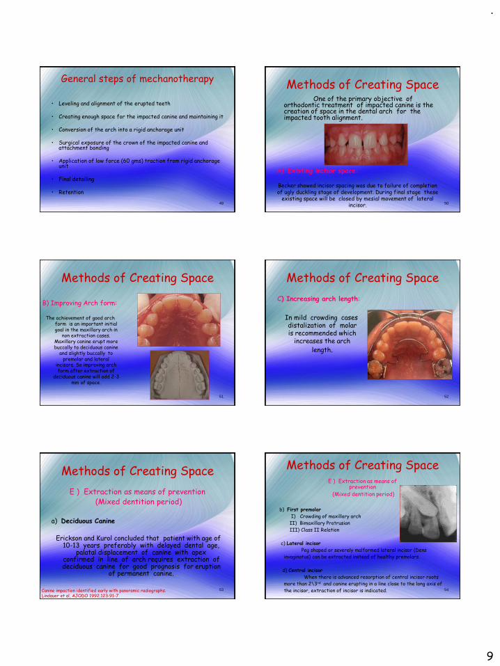
Methods of Creating Space
E ) Extraction as means of prevention(Mixed dentition period)
a) Deciduous Canine
Erickson and Kurol concluded that patient with age of 10-13 years preferably with delayed dental age,
palatal displacement of canine with apex confirmed in line of arch requires extraction of deciduous canine for good prognosis for eruption
of permanent canine.
Canine impaction identified early with panoramic radiographs.Lindauer et al, AJODO 1992;123:91-7
54
Methods of Creating Space
b) First premolar
I) Crowding of maxillary arch
II) Bimaxillary Protrusion
III) Class II Relation
c) Lateral incisor
Peg shaped or severely malformed lateral incisor (Dens
invaginatus) can be extracted instead of healthy premolars.
d) Central incisor
When there is advanced resorption of central incisor roots
more than 2\3rd and canine erupting in a line close to the long axis of
the incisor, extraction of incisor is indicated.
E ) Extraction as means of prevention
(Mixed dentition period)

.
10
55
Anchorage consideration and space maintenance
• Use of full dimension stainless steel rectangular wire in edgewise brackets
• Use of 0.022 / 0.020 wires with uprighting springs or torquing springs to act as brakes if necessary in Beggs and Tip-edge appliance.
Steel tubing – added rigidity and hygieneDeactivated niti coil spring 56
• The microscrew should be placed in the labial cortical alveolar bone, at an angle of 10-20° to the bone surface and as parallel to the tooth's long axis as possible.
• This keeps the apex of the microscrew on the buccal side and reduces the likelihood of its contacting the root.
• The head of the microscrew should be located as incisally as possible to maximize the vertical component of force,
Micro-Implant Anchorage for Forced Eruption of Impacted CaninesPARK et al, JCO 2004; 38; 297-302.
Micro-Implant Anchorage
57
Micro-Implant Anchorage
Micro-Implant Anchorage for Forced Eruption of Impacted CaninesPARK et al, JCO 2004; 38; 297-302.
58
• In lingual treatment, the smaller arches that are required for the shorter interbracket distances and smaller bracket slots may not be able to resist distortion.
• The impacted canine needs to pass over the archwire during buccal movement.
• These considerations make skeletal anchorage for eruption of impacted canines even more appealing in lingual orthodontics than in labial appliance treatment.
MICRO-IMPLANT ANCHORAGE AND LINGUAL APPLIANCE
Micro-Implant Anchorage for Forced Eruption of Impacted CaninesPARK et al, JCO 2004; 38; 297-302.
59
Surgical exposure to allow natural eruption to occur
• Most useful when the canine has a correct axial inclination and does not need to be uprighted during its eruption.
• Clark recommended that a polycarbonate crown be placed over the impacted tooth after its surgical exposure.
• The crown should be made long enough to extend through a window cut in the palatal tissue.
• Often, 6 months to 1 year may elapse before the impacted tooth has erupted sufficiently to permit removal of the polycarbonate crown and its replacement with an orthodontic attachment.
• If the tooth fails to erupt, Clark recommends the removal of any cicatricial tissue surrounding the crown.
MAIN DISADVANTAGES • The spontaneous but slow canine eruption, the increased
treatment time, and the inability to influence the path of eruption of the impacted canine
Clark D. The management of impacted canines: free physiologic eruption. J Am Dent Assoc 1971;82:836-40.
TYPES OF FLAPS FOR IMPACTED CANINE
Buccally accessible impacted teeth
• A circular incision

.
11
Apically repositioned surgical flap Full flap closure
Uncovering labially impacted teeth: apically positioned flap and closed eruption technique.Vermette et al; AO 1995; 65: 23-32.
TYPES OF FLAPS FOR IMPACTED CANINE
62Maintaining ideal tooth-gingiva relationship when exposing and aligning an impacted tooth.Wong-Lee et al; 1985 BJO; 12: 189-92
Palatal Impaction
• Partial
• Full flap closure
TYPES OF FLAPS FOR IMPACTED CANINE
64
Two approaches are generally recommended in regard to the timing
of placing the attachmentTWO-STEP APPROACH.First, the canine is surgically uncovered and the area is packed with a surgical
dressing to avoid the filling in of tissues around the tooth.After wound healing, within 3 to 8 weeks, the pack is removed, and an attachment is
placed on the impacted tooth.
ONE-STEP APPROACHThe attachment is placed on the tooth at the time of surgical exposure The tissues over the attachment should be excised, and a periodontal pack should be
placed. The pack will minimize patient discomfort and prevent the granulation tissues from
covering the attachment before the clinician is ready to apply traction forces on the impacted tooth.
This approach is particularly recommended for palatally impacted teeth. One of the important advantages of such an approach is that when the force is
applied to• the impacted tooth, the clinician is able to visualize the crown of the tooth and
to have better control over the direction of tooth movement. • This will avoid moving the impacted tooth into the roots of the neighboring
teeth.
AJO-DO1998 Volume 1992 Feb SPECIAL ARTICLE - Bishara
65
Attachments For caninea) Lasso wire – Shapira and Kuftinec
1) Poor control over direction of extrusion
2) Risk of external root resorption near CEJ
3) Risk of alveolar crestal bone loss and loss of attachment epithelium
b) Bands -- Vonder Heydt
1) Requires Extensive bone removal
c) Cast canine caps -- Lewis, Dewel
1) Requires extensive crown preparation
AO 1981; 51: 203-7
66
Attachments For canine
d) Threaded pins – Becker and
Zilberman
1) Chances for non vitality of the
tooth
2) Needs restoration of the tooth
at the end of treatment
e) Direct Bonding -- Jacoby,
Nielson
1) Easy to perform
2) More reliable method
AJODO 1978; 74: 422-9 Twin bracket Eyelet

.
12
67
(f) Elastic ties and modules
Advantages
- Application of light forces
- Good range of action
- Easier to tie
Disadvantages
- Tends to loosen
- High degree of force decay
Attachments for canine
68
Attachments For canine
g) Magnets
Developmental stage. Greatest disadvantage is
corrosion.
Method is clumsy and inconvenient
Treatment of an impacted canine with magnets. Darendelier et al; JCO 1994;28:639-43
69
FORCE GENERATING DEVICES
Alignment of Impacted Canines with Cantilevers and Box Loops; Surendra Patel ;
JCO 1999 volume 33 : 2 : 82-85
Cantilever
1. Initial extrusion mechanics with a cantilever.
2. Use of a box loop to continue canine extrusion and to make 1st- and 2nd-order corrections.
3. Incorporation of the canine into a continuous archwire for finishing.
TMA BOX LOOP
• TMA .017 X .025 wire used.
• Produce saggittal and transverse corrections while continuing vertical
eruption.
Alignment of Impacted Canines with Cantilevers and Box Loops; Surendra Patel ;
JCO 1999 volume 33 : 2 : 82-85
FORCE GENERATING DEVICES
71
Cantilevers
FORCE GENERATING DEVICES
Cantilever Mechanics for Treatment of Impacted CaninesFISCHER et al; JCO NOVEMBER 2000
Buccal impaction0.017 x 0.025 TMA
Palatal impaction0.016 x 0.025 TMA
NICKEL TITANIUM CLOSED-COIL SPRING
• 0.009”X 0.041” spring
• Provides 80 gm of force when stretched to twice its resting
length
TECHNIQUE CLINIC Nickel Titanium Closed-Coil Spring for Extrusion of Impacted Canines; LORING L. ROSS; JCO1999; VOLUME 33 : NUMBER 2 : PAGES (99-100)
FORCE GENERATING DEVICES

.
13
THE MONKEY HOOK
It is a simple auxiliary with an open loop on each end for the attachment of intra oral elastic or elastomeric chain or for connecting to a bondable loop button.
The Monkey Hook: An Auxiliary for Impacted, Rotated, and Displaced Teeth.
S. JAY BOWMAN et al; JCO 2002 July
FORCE GENERATING DEVICES
74
Alternative is forming a coil on the place where canine should lie at the end of rx andApplying traction using monkey loop
Application of force in differentplanes possible with monkey loop Application of traction from lower jaw
The Monkey Hook: An Auxiliary for Impacted, Rotated, and Displaced Teeth.
S. JAY BOWMAN et al; JCO 2002 July
THE MONKEY HOOK
AUSTRALIAN HELICAL ARCHWIRE
•Made in special plus .016” arch wire
•Force should not exceed 200 gm
• Activation by twisting the steel
ligature wire every two weeks
Eruption of impacted canines with an australian helical archwire
Hauser et al; JCO sep 2000
FORCE GENERATING DEVICES
76
77
Two Stage Traction
Palatally impacted canine
When crown of canine is more palatally displaced,surgery on the buccal side needs to become more radical,rendering a palatal; approach preferable.
Usually palatally impacted tooth is guided to occlusion in two stages.
I) Guiding tooth to oral environment
II) Guiding tooth to line of arch
78
Guiding Tooth To Oral Environment
1) Active palatal arch (Becker 1978)
It consist of fine 0.020 inch removable palatal arch
wire carrying an omega loop on each side. End of the wire
is double-ended for Frictionless fit in lingual sheath. It is
activated by elevating downward activated palatal arch
wire and hooking the pigtail ligature around it.

.
14
79
Guiding Tooth To Oral Environment
2) Ballista Spring (Jacoby 1979)
It is made of rectangular wires. It proceeds forward until it is opposite to canine space and bent vertically
downwards and terminate into a small loop.With slight finger pressure ,spring is tied to pigtail ligature. By this it
provide an extrusive force for the canine to erupt. 80
Guiding Tooth To Oral Environment
3) Light Auxiliary Labial Arch (Kornhauser1996)
It is made up of 0.014 inch round SS wire with vertical
loops in the area of impacted canine on both sides. This
loop has a small helix. This wire is tied with the basal arch
wire in piggyback fashion. If basal arch wire is not used it
will leads to extrusion of adjacent tooth and cause
alteration of occlusal plane .
THE K- 9 SPRING
• Made in 0.017”X 0.025”TMA wire
• Simple in design
• Low cost
• No patient compliance
• Light continuous eruptive and distalizing forces
The K-9 Spring for Alignment of Impacted CaninesVarun Kalra; JCO Oct 2000
Guiding Tooth To Oral Environment
MANDIBULAR ACHORAGE
•Lingual arch is fabricated with 0.036 inch SS wire
•Vertical hooks (5-6mm in length)
•Elastic force should not exceed 40-60 gm
•confirmation of ankylosis of the impacted tooth is suspected •in cases where the maxillary arch is unsuitable for providing anchorage.
Management of impacted maxillary canines using mandibular anchorage
Pramod K. Sinha, and Ram S. Nanda; AJODO March 1999
Guiding Tooth To Oral Environment
Samarium cobalt magnet coated with thermoplastic material (Eurcodur).
Communication of the impacted tooth with the oral cavity can cause periodontal tissue damage.
the continuous force applied to the palatal mucosa by a ligature wire can be quite painful, especially after activations.
treatment is less traumatic and poses less risk of infection than conventional orthodontic methods
MAGNETS
Case Report :Treatment of an Impacted Canine with MagnetsM. ALI DARENDELILER, MARC FRIEDLI, JCO 1994; Nov(639 - 643).
Guiding Tooth To Oral Environment
84
Deep infraosseous impacted canines.
Technique allows for orthodontic traction
of the impacted tooth to the center
of the alveolar ridge.
Creates the natural path of eruption.
Tunnel traction of infraosseous impacted maxillary canines –Tunnel traction of infraosseous impacted maxillary canines. A three-year periodontal follow-up. Crescini et al. AJO-DO, Volume 1994 Jan (61 - 72):
Tunnel traction

.
15
85
Tunnel traction
86
Corticotomy-assisted Exposure of Palatally Impacted Canines
Orthodontic Treatment Acceleration with Corticotomy-assisted Exposure of Palatally Impacted Canines A Preliminary StudyT. J. Fischer. Angle Orthodontist, Vol 77, No 3, 2007
CONCLUSIONS• The results demonstrated that under the same conditions the corticotomy-assisted approach produced faster tooth movement in all six patients.• Additionally, this surgical procedure did not produce any significant difference in the periodontal health of the canine.
87
If the root apex of canine is mesial to lateral incisor or distal to premolar , tooth is considered as TRANSPOSED.
I) Incomplete transposition: Roots will be in line of arch in its position and crown tipped due to path of eruption. (uprighting of tooth will align the tooth in arch).
II) Complete transposition: Both crown and root together will be completely interchanged.
Canine transposition
88
TREATMENT OPTIONS
•To resolve the transposition to ideal relationship
•To align the transposed canine where it is erupting
•Use canine for auto transplantation into prepared socket
in ideal site
•To extract severely displaced canine, lateral incisor or
premolar depending upon prognosis
Canine transposition
89Maxillary Canine—First Premolar Transposition. Restoring Normal Tooth Order With Segmented MechanicsFilho et al. Angle Orthodontist, Vol 77, No 1, 2007
Canine transposition
90
Auto transplantation
Transalveolar transplantation of maxillary caninesSagne, Lennartsson, and Thilander; AJO-DO Volume 1986 Aug (149 - 157)

.
16
91
1. Patient's ability to cooperate is critical.2. Procedure is best performed when the root length of the transplant is
between one half and three fourths complete.3. The recipient site must be healthy and of adequate size to receive the
transplant; it is important that the recipient site be prepared before the transplant is made available.
4. Tremendous care must be exercised not to insult the root surface; wherever possible, the transplant should be handled only by its crown.
5. The length of time from removal to reinsertion should be minimal; ideally, this is a nonstop relocation. Desiccation of the periodontal ligament can cause resorption, ankylosis, and failure.
6. Circumdental ligation with metallic sutures is contraindicated.7. Soft-tissue reproximation and ligation with silk sutures constitute a
preferred form of fixation during the first ten days.8. Further stabilization can be employed through direct bonding, if
necessary, for from 10 days to 6 weeks . After this time the tooth should be treated like any other tooth of similar developmental stage.
9. The chance of a favorable prognosis for a properly prepared autogenic dental transplant can approach 100 percent.
AJO-DO Volume 1980 Feb (146 - 162): Autogenic tooth transplantation - Northway
Auto transplantation Dentigerous Cyst
Dentigerous cyst may inhibit the eruption of the involved canine.
Treatment:• Marsupialization is the procedure consists of fenestrating the outer
wall of the cyst, and relieving the intracystic pressure.
• With this early decompression, the size of the cavity slowly
decreases, enabling the surrounding bone to regenerate around the
impacted tooth, which eventually erupt the tooth into the dental arch.
• No traction should be applied until bone regenerates to an acceptable
level, as the periodontal apparatus of such a tooth is weak and will lead
to compromised long term prognosis
93
Success rate and duration of treatment
• Younger patients required a longer treatment.
• The younger the patient, the more severely impacted the canine.
• If the canine was impacted less than 14 mm from the occlusal plane, treatment duration averaged 23.8 months;
• If the canine was impacted more than 14 mm from the occlusal plane, treatment duration averaged 31.1 months.
Factors that relate to treatment duration for patients with palatally impacted maxillary canines. Jeffrey A. Stewart (AJODO 2001;119:216-25)
94
• The success rate among the adults was 69.5% compared with 100% among the younger controls
• The adults showed significant increase in the duration and number of treatment visits required for resolving the canine impaction, in both the simpler and the more difficult cases.
• It was concluded that the prognosis for successful orthodontic resolution of an impacted canine worsens with age.
Success rate and duration of treatment
Success rate and duration of orthodontic treatment for adult patients with palatally impacted maxillary canines. Adrian Becker, AJODO 2003;124:509-14
95
A rough prediction can be made for number of visits required:
● Patients aged more than 25 years require remarkably longer treatments than younger patients (30 additional visits on average).
● The canines with cusp tips farther from the occlusal plane require longer treatments: 1 additional visit was required if the distance increased by 0.63 mm in the panoramic radiograph.
● The canines with cusp tips located mesially to the axes of the lateral incisors required 10 more visits than the distally located canines on average.
Factors associated with the duration of forced eruption of impacted maxillary canines:A retrospective study. Zuccati et al, AJODO 2006;130:349-56
Success rate and duration of treatment
96
Impacted Canines And Root Resorption Of Incisors
• Resorption of roots stops when canine impaction has been solved.
• Subsequent orthodontic movement of resorption affected teeth does not generate further resorption.
• Incisors with severely resorbed roots have high survival rate.
• Teeth remain vital, and retain their color, and appearance.
• Teeth show very low degree of mobility and an improvement in periodontal bone support following post treatment retention.
• Splinting is not usually necessary. Long-term follow-up of severely resorbed maxillary incisors after resolution of an etiologically associated impacted canine. Adrian Becker; AJODO 2005;127:650-4

.
17
Impacted canine and Periodontium
1. Labially impacted maxillary anterior teeth uncovered with an apically positioned flap technique have more unaesthetic sequalae than those uncovered with a closed-eruption technique.
2. Negative esthetic effects, such as increased clinical crown length, increased width of attached tissue, gingival scarring, and intrusive relapse were evident in the teeth treated with an apically positioned flap.
Uncovering labially impacted teeth: apically positioned flap and closed-eruption techniques Vermette et al; Angle Orthodontist 1995 No. 1, 23 - 33:
Apically positioned flap vs closed eruption
Surgical exposure, orthodontic movement, and final tooth position as factors inperiodontal breakdown of treated palatally impacted canines. Kohavi et al; AJODO 1984;85:72-7.
Impacted canine and Periodontium
Bone support levels graph – dark (untreated)
X1 – min surgery with primary closureXh – follicular sac removed till CEJ
M1 – tipping, extrusion, rotation movements onlyMh – root uprighting & torquing movements
Evaluation of post treatment alignment by Becker et al
• Incidence of rotations and spacing
1. Impacted side - 17.4%
2. Control side - 8.7%
• Ideal alignment on control side is twice as often as the impacted side.
Retention considerations
Impacted maxillary canines: A review; Samir E. Bishara; AJODO 1992;101:159-71
To minimize rotational relapse, options available are
1. Fiberotomy
2. Bonded fixed retainer
Clark’s suggestion for palatally impacted canine: Lingual drifting
can be prevented by removal of half moon- shaped wedge of
tissue from lingual aspect of canine.
Retention considerations
Impacted maxillary canines: A review; Samir E. Bishara; AJODO 1992;101:159-71
101
Buccally impacted maxillary canines
• Primary etiology is crowding
• Fournier et al suggest that labially impacted teeth with a favorable vertical position may be treated initially by surgical exposure but without the application of a traction force.
• He believes that in younger patients the tooth will erupt on its own after surgical exposure, whereas in older patients traction is almost always indicated.
• The attached gingiva could be made available through an apically repositioned flap, a laterally repositioned pedicle graft, or, when necessary, a free gingival graft.
Impacted maxillary canines: A review; Samir E. Bishara; AJODO 1992;101:159-71102
When to extract impacted canines?
(1) If it is ankylosed and cannot be transplanted, (2) if it is undergoing external or internal root
resorption, (3) if its root is severely dilacerated, (4) if the impaction is severe (e.g., the canine is lodged
between the roots of the central and lateral incisors and orthodontic movement will jeopardize these teeth)
(5)If the occlusion is acceptable, with the first premolar in the position of the canine and with an otherwise functional occlusion with well-aligned teeth
(6) if there are pathologic changes (e.g., cystic formation, infection), and the patient does not desire orthodontic treatment.
Impacted maxillary canines: A review; Samir E. Bishara; AJODO 1992;101:159-71

.
18
103
Canine vs. premolar extraction• The prognosis for the successful exposure and
guidance of the canine to its proper position in the dental arch is often guarded.
• This is because the canine may be ankylosed, undergo resorption, or become nonvital.
• If the overall orthodontic treatment plan involves the removal of premolars, it is advisable to postpone their extractions until the canine is surgically exposed and orthodontic forces are applied.
• This is done to ensure the feasibility of moving the impacted tooth before extracting a workable replacement.
Impacted maxillary canines: A review; Samir E. Bishara; AJODO 1992;101:159-71104
Mandibular canines
• Not much is present in literature about mandibular canines as its occurrence is a rare condition.
• For lingually placed canine, attachment has to be bonded on buccal surface only, buccal surgical exposure preferred.
• Treatment principles are same as followed during maxillary canines, keeping the final prognosis in mind
105
Canine impactions in adults
Aesthetic consideration is an added point
to be considered in adult Rx of
impacted canines.
Removable prosthesis
Buccal wire with a pontic
Bonded pontic to adjacent teeth106
ConclusionThe management of the severely impacted canine is
often a complex undertakingand requires the joint expertise of a number of
clinicians. It is important that these clinicians
communicate with each other to provide the patient with an optimal treatment plan based on
scientific rational.
107
Thank You

.
1
CEPHALOMETRICS
Presented by: Dr. Naveen Sharma
CONTENTS
• HISTORY
• TECHNICAL ASPECTS
• TRACING TECHNIQUE
• CEPHALOMETRIC LANDMARKS
• CEPHALOMETRIC ANALYSIS
• APPLICATION OF CEPHALOMETRICS
• ERRORS OF CEPHALOMETRIC MEASUREMENTS
• METHODS OF CONTROLLING ERRORS
• STANDARDIZATION OF IMAGE GEOMETRY
• LIMITATIONS OF CEPHALOMETRICS
• DIGITAL CEPHALOMETRY
• CONCLUSION
HISTORYHistory prior to the advent of radiography begins with the attempts of the scientists to classify the human physiques.
Basically it stems from the history of Anthropometry.
Human forms have been measured for many reasons
1.To aid self portrayal in
- sculpture
- drawing
- painting
2. To test the relation of physique to health, temperament and behavioral traits.
Radiographic cephalometry- Alexander Jacobson
Vitruvivous pollio
.
2
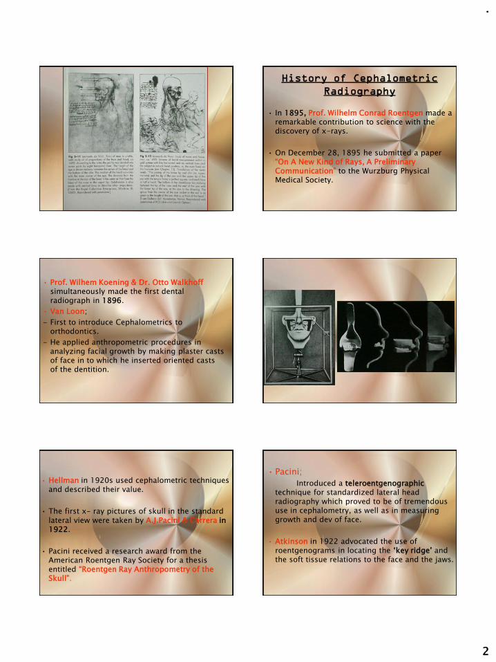
History of Cephalometric
Radiography
• In 1895, Prof. Wilhelm Conrad Roentgen made a remarkable contribution to science with the discovery of x-rays.
• On December 28, 1895 he submitted a paper “On A New Kind of Rays, A Preliminary Communication” to the Wurzburg Physical Medical Society.
• Prof. Wilhem Koening & Dr. Otto Walkhoffsimultaneously made the first dental radiograph in 1896.
• Van Loon;
- First to introduce Cephalometrics to orthodontics.
- He applied anthropometric procedures in analyzing facial growth by making plaster casts of face in to which he inserted oriented casts of the dentition.
• Hellman in 1920s used cephalometric techniques and described their value.
• The first x- ray pictures of skull in the standard lateral view were taken by A.J.Pacini & Carrera in 1922.
• Pacini received a research award from the American Roentgen Ray Society for a thesis entitled “Roentgen Ray Anthropometry of the Skull”.
• Pacini;
Introduced a teleroentgenographictechnique for standardized lateral head radiography which proved to be of tremendous use in cephalometry, as well as in measuring growth and dev of face.
• Atkinson in 1922 advocated the use of roentgenograms in locating the ‘key ridge’ and the soft tissue relations to the face and the jaws.

.
3
• In 1923 Mc Cowen used profile roentgenograms for orthodontic purposes to visualize the relationship between the hard and soft tissues and to note changes in profile which occur during treatment.
• In 1931 cephalometric radiography came to full function when B. Holly Broadbent in USApublished methods to obtain standardized head radiographs in the Angle Orthodontist (A new X ray tech & its application to orthodontia).
• H. Hofrath simultaneously published the same in Fortschritte der Orthodontie in Germany.
• The interesting fact is that Broadbent was an Orthodontist, whereas Hofrath was a Prosthodontist.
• This development enabled orthodontists to capture the field of cephalometry from the anatomists and anthropologists.
Broadbent’s contribution
1. Broadbent’s interest in craniofacial growth began with his orthodontic education under E.H. Angle in 1920.
2. He continued to pursue that interest along with his orthodontic practice, working with a leading anatomist J.Wingate Todd
3. During 1920’s he refined the craniostat in tocraniometer.
4. That proved to be the first step in the evolution of craniostat in to a radiographic cephalostat.
5. He published methods to obtain standardized head radiographs in the Angle Orthodontist(1931) (A new X-ray tech & its application to orthodontia).
• The diagnosing dental deformities by means of planes & angles was first proposed in 1922 by Paul Simon in his book, “Fundamental Principles of a Systematic Diagnosis of Dental Anomalies”.
• Although his “Law of the Canines” was later disproved by Broadbent, his theories stimulated Broadbent to apply the principles of craniometry to living subjects.
• Hofrath’s technique differed from Broadbent’s in that the path of the central ray was not fixed in relation to the head.
• In 1937, using serial records of twins; Broadbent showed how growth – or its lack –was the greatest limiting factor in clinical success.
• In 1943 he stipulated that eruption of the third molars had no ill effect on the denture, particularly the lower incisors.
• Brodie, in a landmark study, corroborated Broadbent’s contention that the growth patternof the normal child’s face develops in an orderly downward and forward fashion and that the pattern, once attained at an early age, did not change.

.
4
Thompson and Brodie in a report on the rest position of the mandible, concluded that:
• The morphogenetic pattern of the head was established at a very early age and did not change.
• The presence or absence of teeth has little bearing on the form or the rest position of the mandible.
• Vertical facial proportions are constant throughout life.
• Margolis (1943) wrote on the relationship between the inclination of the lower incisor and the incisor-mandibular plane angle.
• In 1947 Margolis contributed his maxillo-facial triangle.
THE TECHNICAL
ASPECTS
The basic components of the equipment for producing the lateral cephalogram are:
1. An X-ray apparatus
2. An image receptor system
3. A cephalostat
Oral Radiology, Principles and interpretation- White and Pharoah (5th edition)
THE X- RAY APPARATUS
The three basic elements that generate that X-ray are:
A. Cathode
B. Anode
C. The electrical power supply.
Oral Radiology, Principles and interpretation- White and Pharoah (5th edition)
CATHODE
• Tungsten filamentsurrounded by a molybednum focusing cup.
• Connected to a low voltage & high voltage circuit.
• A step down transformersupplies the low voltage circuit with 10V and a high current to heat the filament un till the electrons are emitted.
Oral Radiology, Principles and interpretation- White and Pharoah (5th edition)

.
5
STEP UP TRANSFORMER
• Supplies the high voltage circuit with 65-90kV.
• Differential potential accelerates the electrons.
• The electron beam is directed by the focusing cup to strike a small target in the anode called focal spot.
Oral Radiology, Principles and interpretation- White and Pharoah (5th edition)
ANODE
• Small tungsten block embedded in the copper stem, which stops the accelerated electrons whose kinetic energy causes the production of photons.
• Less then 1% is converted to photons, rest is converted to heat.
• Although tungsten is a high molecular substance, its thermal resistance is unable to withstand the heat.
Oral Radiology, Principles and interpretation- White and Pharoah (5th edition)
THE IMAGE RECEPTOR SYSTEM
It records the final product of X-Rays after they pass through the subject. The extraoral projection like the lateral cephalometric technique, requires a complex image receptor system that consists of :
1. Extraoral film
2. Intensifying screen
3. A cassette
4. A grid & a soft tissue shield
THE CEPHALOSTAT
Ear rod
forehead clamp
1.Ear rod2.Forehead clamp3.Infra orbital pointer4.Cassette holder
Cassette holder
Radiographic cephalometry- Alexander Jacobson
X-Ray Source position
• It is positioned 5 feet(152.4cm) from the subject’s midsagittal plane.
Film position
To minimize variations in magnification from patient to patient& to obtain consistent measurements on the patient over time, a distance of 15cm is often used.
Radiographic cephalometry- Alexander Jacobson
15"60"
Source Plane
X-ray Source
Patient in Head Positioning
Device
Mid-Sagittal Plane
Film Plane
X-ray Film in
Cassette
152.4 cms

.
6
PATIENT POSITIONING;
• It is based on the same principles that described by the Broadbent.
• The patients head is fixed by the two ear rods.
• The head which is centered in the cephalostat, is oriented with the Frankfurt plane parallel to the floor & the midsagittal plane vertical & parallel to the cassette.
Ear rod
LATERAL CEPHALOGRAM
Radiographic cephalometry- Alexander Jacobson
• The standardized Frankfurt plane is achieved by placing the infraorbital pointer at the patients orbit and then adjusting the head vertically until the infraorbital pointer & the two ear rods are at the same levels.
• The upper part of the face is supported by the forehead clamp, positioned at the nasion.
Ear rod
forehead clampcassette
Radiographic cephalometry- Alexander Jacobson
• Identical to that of lateral ceph except that the Patient is facing the film.
• Patient mid saggital plane is perpendicular to the film plane.
• FH plane is horizontal.
• Canthomeatal line directed upward by 100.
PATIENT POSITIONING;
PA CEPHALOMETRIC
RADIOGRAPH
Radiographic cephalometry- Alexander Jacobson
Shortcomings of the
Frankfurt horizontal
plane
• Some individuals show a variation of their FH
plane to the true horizontal to an extent of 10°.
• The landmarks to locate the FH plane on a cephalogram, orbitale & porion, are difficult to locate accurately on the radiographs.
Am J Phys. Anthropol. 16: 1956
• An alternative to overcome this was to use a functionally derived NHP.According to Morrees & Kean.
• It was obtained by the patient standing up & looking directly into the reflection of his/her eyes in a mirror directly ahead in the middle of the cephalostat.
• To record the NHP,the ear rods are not used for locking the patient head into a fixed position but serve to place the midsagittal plane at a fixed distance from the film plane.
Am J Phys. Anthropol. 16: 1956
TRACING TECHNIQUE

.
7
Tracing supplies and
equipments
• A lateral cephalogram
• Acetate matte tracing paper(.003 inches
thick, 8×10 inches)
• A sharp 3H drawing pencil or a very fine tipped pen
• Masking tape
• A few sheets of cardboard (preferably black) and a hollow cardboard tube.
Radiographic cephalometry- Alexander Jacobson
• A protractor and tooth symbol tracingtemplate for drawing the teeth. Also templates for tracing the outlines of ear rods.
• Dental casts trimmed to maximum intercuspation of the teeth in occlusion.
• Viewbox (variable rheostat desirable but not essential).
• Pencil sharpener and a eraser.
Radiographic cephalometry- Alexander Jacobson
Tracing of a Cephalogram
• Thorough familiarity with the gross anatomy is required before the tracing.
• By convention the bilateral structures (eg, the rami and inferior borders of the mandible) are first traced independently. An average is then drawn by visual approximation, which is represented by a broken line.
Radiographic cephalometry- Alexander Jacobson Radiographic cephalometry- Alexander Jacobson
General considerations for
the tracing
• Start by placing the cephalogram on the viewbox with the patient’s image facing towards the right.
• Tape the four corners of the radiograph to the viewbox.
• Draw three crosses on the radiographs, two within the cranium and one over the area of the cervical vertebrae (registration crosses).
Radiographic cephalometry- Alexander Jacobson
• Place the matte acetate film over the radiograph and tape it securely.
• After firmly affixing the acetate film, trace the three registration crosses.
• Print the pt name, record number, age in years and months, the date on which the cephalogram was taken and your name on the bottom left corner of the acetate film.
• Begin tracing using smooth continuous pressure.
Radiographic cephalometry- Alexander Jacobson

.
8
Stepwise tracing technique
1. Tracing the soft tissue profile, external cranium and the vertebrae,
2. Tracing the cranial base, internal border of the cranium, frontal sinus and the ear rods,
3. Maxilla and related structures including the nasal bone and pterygomaxillary fissure,
4. The mandible.
Radiographic cephalometry- Alexander Jacobson
CEPHALOMETRIC
LANDMARKS
A landmark is a point which serves as a guide for measurement or construction of planes. They are divided into two types:
1. Anatomic: These represent actual anatomic structure of the skull.
2. Constructed: These have been constructed or obtained secondarily from anatomic structures in the cephalogram.
Radiographic cephalometry- Alexander Jacobson
Requisites for a landmark
• Landmark should be easily seen on the roentegenogram, be uniform in outline, and easily reproducible.
• Lines and planes should have significant relationship to the growth vectors of specific areas.
• Landmark should permit valid quantitative measurement of lines and angles.
Radiographic cephalometry- Alexander Jacobson
• Measurement should have significant relation to the information sought.
• Measurements should be amenable to statistical analysis but should preferably not require extensive specialized training in statistical methods.
• Following is the list of most commonly used Cephalometric landmarks.
Radiographic cephalometry- Alexander Jacobson
LATERAL CEPHALOGRAM

.
9
Point A revisited – Jacobson- AJO 1980
Point A cannot be accurately identified in all cephalometric
radiographs.. In instances where this landmark is not clearly
discernible, an alternative means of estimating the anterior extremity
of the maxillary base is shown.
Procedure;
A point plotted 3.0 mm. labial to a point between the upper third and
lower two thirds of the long axis of the root of the maxillary central
incisor was found to be a suitable point - (estimated point A) through
which to draw the NAE line and one which most closely approximates
the true NA plane.
3mm
Cephalometric planes
1. Are derived from at least 2 or 3 landmarks
2. Are used for;
- measurements,
- separation of anatomic divisions,
- definition of anatomic structures of relating parts of the face to one another.
The various cephalometric planes used are:
1. Horizontal planes
2. Vertical planes
Sella-Nasion
plane:
Frankfurt
Horizontal
plane: (The name is given in the conference of anthropology,held at Frankfurt in1985)

.
10
Basion-Nasion
plane
Palatal plane
Occlusal
plane
Mandibular
plane:
1.Salzmann took lower border of the mand.
2. Go – Me- Mc Namara- Rakosi- COGS
3. Go – Gn- Steiners’s
Vertical
planes;
• Facial plane• Ramal plane• Y- Axis• NA• NB
CEPHALOMETRIC ANALYSIS
Principle of Cephalometric
analysis
• The goal is to compare the patient with a normal reference group, so that differences between the patient’s actual dentofacial relationships and those expected for his/her racial or ethnic groups are revealed.
• First popularized after world war-II in the form of Down’s analysis.
• The standards developed for the Down’s analysis are still useful but have been largely replaced by newer standards, based on less rigidly selected groups.

.
11
Two basic ways to approach
this goals are:
• Use of selected linear and angularmeasurements to establish the appropriate comparisons.
eg; Down’s analysis.
• Template method: Express the normative data graphically and to compare the patient’s dentofacial form directly.
MEASUREMENT ANALYSIS
HARD TISSUE ANALYSIS
• DOWN’S• TWEED’S• WITS APPRAISAL• STEINER’S• Mc NAMARA’S• RAKOSI’S• SCHWARZ• COGS
SOFT TISSUE
ANALYSIS
• HOLDAWAY’S
• ARNETT
- FH plane is used as the reference plane.
- It was based on the study of 25 white subjects who had good occlusion and proportional facial skeleton.
- This analysis indicates whether the dysplasia is in the facial skeleton or in the dentition or both.
DOWN’S ANALYSIS TWEED’S ANALYSIS
Tweed used three planes to establish a diagnostic triangle, the three planes used in this analysis are:
1. Frankfurt horizontal plane
2. Mandibular plane
3. Long axis of lower incisor
TWEED’S
TRIANGLEThe values of the angles according to Tweed’s finding are as follows:
1. FMA = 25°
2. FMIA = 65°
3. IMPA = 90°
.
12
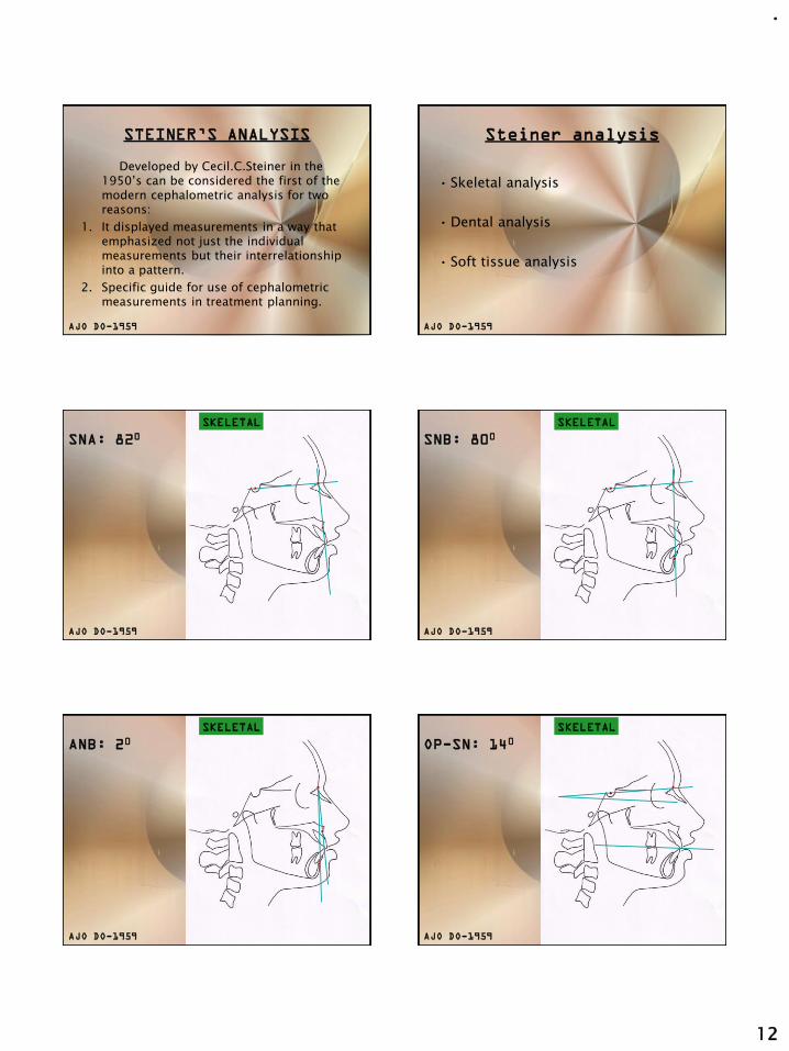
STEINER’S ANALYSIS
Developed by Cecil.C.Steiner in the 1950’s can be considered the first of the modern cephalometric analysis for two reasons:
1. It displayed measurements in a way that emphasized not just the individual measurements but their interrelationship into a pattern.
2. Specific guide for use of cephalometric measurements in treatment planning.
AJO DO-1959
Steiner analysis
• Skeletal analysis
• Dental analysis
• Soft tissue analysis
AJO DO-1959
SNA: 820SKELETAL
AJO DO-1959
SNB: 800SKELETAL
AJO DO-1959
ANB: 20SKELETAL
AJO DO-1959
OP-SN: 140SKELETAL
AJO DO-1959

.
13
MP-SN: 320SKELETAL
AJO DO-1959
UI-NA= 220
UI-NA= 4mm
DENTAL
NA
AJO DO-1959
LI-NB = 250
LI-NB = 4mm
DENTAL
NB
AJO DO-1959
INTERINCISAL
ANGLE: 1300
DENTAL
AJO DO-1959
SOFT TISSUE ANALYSIS
STEINER’S
S-LINE
AJO DO-1959
The mean values for Steiner’s analysis
are as follows:
SNA 82°
SNB 80°
ANB 2°
SND 76°
Upper incisor to NA 22°
Upper incisor to NA 4mm
Lower incisor to NB 25°
Lower incisor to NB 4mm
interincisal angle 130°
MP to SN 32°

.
14
McNAMARA ANALYSIS
Divided craniofacial skeletal complex into 5 major sections;
1. Maxilla to cranial base.
2. Maxilla to mandible.
3. Mandible to cranial base.
4. Dentition.
5. Airway.
NASOLABIAL
ANGLE: 1020
MAX TO CRANIAL BASESOFT TISSUE
EVALUATION
Pt A-N
Perpendicular:
1.mixed dentition=
0mm
2.adult= 1mm
MAX TO CRANIAL BASEHARD TISSUE
EVALUATION
1. EFF MAX LENGTH
MAX TO MANDIBLE
91
117
ANTEROPOSTERIOR
2.EFF MAND LENGTH
Ans-Me
VERTICAL MAX TO MANDIBLE
Mand plane
angle
MP-FH: 220
SKELETAL
AJO DO-1959

.
15
Facial axis
angle= 900
SKELETAL
AJO DO-1959
900- obtained Pog-N Perpen
1. mixed dent
(6-8mm)
2.female=(-4-0)
3.males =(+/-2)
MANDIBLE TO CRANIAL BASE
MAX INCISOR
POSITION
DENTITION
4-6mm
MAND INCISOR
POSITION
DENTITION
1-3mm
Upper pharynx=15-20mm
Lower pharynx=11-14mm
AIRWAYWITS APPRAISAL
• Indicates antero-posterior disharmonies of the jaws.
• It’s a linear measurement, not an analysis
• Was developed as a shortcoming to ANB.

.
16
Shortcomings
of ANB
AO-BO
1. Sk Cl-I ; BO 1mm front of AO2. Sk Cl-II; BO is behind AO3. Sk Cl-III; BO is ahead of AO
DRAWBACKS;
1.Value varies with occ plane.2.Value varies with dist betw points A and B3.OP is not the actual plane and the left and the
right side do not always coinside in a lateral ceph
RAKOSI JARABAK’S ANALYSIS
1. Cephalometric radiography; Thomas Rakosi.
Saddle Angle
1230+/-5
1. Cephalometric radiography; Thomas Rakosi.
ARTICULAR ANGLE
1430+/- 6
1. Cephalometric radiography; Thomas Rakosi.

.
17
GONIAL ANGLE
Gonial angle
=1280+/-7
U=52-55
l=72-75
1. Cephalometric radiography; Thomas Rakosi.
SUM OF POST ANGLES
396+/-60
1. Cephalometric radiography; Thomas Rakosi.
MAND PLANE ANGLE
MP-SN=320
1. Cephalometric radiography; Thomas Rakosi.
ANGLE OF INCLINATION
850
1. Cephalometric radiography; Thomas Rakosi.
Pn-OP
750
1. Cephalometric radiography; Thomas Rakosi.
Pn-MP
650
1. Cephalometric radiography; Thomas Rakosi.

.
18
BASAL PLANE ANGLE
250
1. Cephalometric radiography; Thomas Rakosi.
Ant-Post face Ht
62-65%
1. Cephalometric radiography; Thomas Rakosi.
Inter-Incisal
1350
1. Cephalometric radiography; Thomas Rakosi.
UI-SN
1020+/-2
1. Cephalometric radiography; Thomas Rakosi.
UI-PP
700+/-5
1. Cephalometric radiography; Thomas Rakosi.
LI-MP
900 +/-3
1. Cephalometric radiography; Thomas Rakosi.

.
19
CEPHALOMETRICS FOR
ORTHOGNATHIC SURGERY
1. Cephalometric analysis specially designed for the patient who requires maxillofacial surgery.
2. Landmarks and measurements were made which could be altered by common surgical process.
J Oral Surgery:vol-36, April 1978
3.The comprehensive appraisal includes all of the facial bones and a cranial base reference.
4. Rectilinear measurements can be readily transferred to a study cast for mock surgery.
5. Critical facial skeletal components are examined.
6. Standards and static's are available for variations in age and sex.
7. Systematised approach to measurements that can be computerised.
8. COGS appraisal describes dental, skeletal and soft tissue variations.
J Oral Surgery:vol-36, April 1978
1.Ar-Ptm
2.Ptm-N
J Oral Surgery:vol-36,April 1978
CRANIAL BASE
Ar-Ptm
Ar-N
Ptm-N
HP
1.N-A-Pg(ANGLE)
2.N-A (ll-HP)
3.N-B (ll-HP)
4.N-Pg(ll-HP)
J Oral Surgery:vol-36,April 1978
HORIZONTAL(SKELETAL)
HP
1.N-A-Pg(ANGLE)
2.N-A (ll-HP)
3.N-B (ll-HP)
4.N-Pg(ll-HP)
J Oral Surgery:vol-36,April 1978
HORIZONTAL(SKELETAL)
HP
1.N-ANS(PER-HP)
2.ANS-Gn(PER-HP)
3.PNS-N(PER-HP)
4.MP-HP(ANGLE)
5.UI-NF(PER-NF)
6.U6-NF(PER-NF)
7.LI-NF(PER-NF)
8.L6-NF(PER-NF)
J Oral Surgery:vol-36,April 1978
VERTICAL(SKELETAL,DENTAL)
HP
N-ANS
ANS-Gn
PNS-N

.
20
1.N-ANS(PER-HP)
2.ANS-Gn(PER-HP)
3.PNS-N(PER-HP)
4.MP-HP(ANGLE)
5.UI-NF(PER-NF)
6.U6-NF(PER-NF)
7.LI-NF(PER-NF)
8.L6-NF(PER-NF)
J Oral Surgery:vol-36,April 1978
VERTICAL(SKELETAL,DENTAL)
HP
1.PNS-ANS(II-HP)
2.Ar-Go (LINEAR)
3.Go-Pg (LINEAR)
4.B-Pg (II-MP)
5.Ar-Go-Gn(ANGLE)
J Oral Surgery:vol-36,April 1978
MAX & MAND
HP
1.PNS-ANS(II-HP)
2.Ar-Go (LINEAR)
3.Go-Pg (LINEAR)
4.B-Pg (II-MP)
5.Ar-Go-Gn(ANGLE)
J Oral Surgery:vol-36,April 1978
HP
MAX & MAND
1.U OP-HP(ANGLE)
2.L OP-HP(ANGLE)
3.A-B (II-OP)
4.UI-NF(ANGLE)
5.LI-MP(ANGLE)
J Oral Surgery:vol-36,April 1978
DENTAL
HP
1.U OP-HP(ANGLE)
2.L OP-HP(ANGLE)
3.A-B (II-OP)
4.UI-NF(ANGLE)
5.LI-MP(ANGLE)
J Oral Surgery:vol-36,April 1978
HP
DENTAL
1.U OP-HP(ANGLE)
2.L OP-HP(ANGLE)
3.A-B (II-OP)
4.UI-NF(ANGLE)
5.LI-MP(ANGLE)
J Oral Surgery:vol-36,April 1978
HP
DENTAL

.
21
THE HOLDAWAY SOFT-TISSUE
ANALYSIS
• The analysis outlines the parameters of soft tissue balance.
• Consists of 11 measurements.
Facial angle
(900)
Upper lip
curvature;2.5mm
Skeletal
convexity at
point A;+/-2mm
H-angle; 7-150
Nose tip to H-
line; 12mm max

.
22
Upper sulcus
depth;5mm
Lower sulcus
depth;15mm
Lower lip to H-
line; 5mm
Upper lip
thickness; 15mm
Upper lip stain;
within 1mm
Soft tissue chin
thickness; 10-12mm
TEMPLATE ANALYSIS
• In the early years of cephalometric analysis, it was recognized that representing the norm in graphical form might make it easier to recognize a pattern of relationship.
• In recent years, direct comparisons of patients with templates derived from the various growth studies has become a reliable method of analysis.
- One of the objectives of any analytic approach is to reduce the practically infinite set of possible cephalometric measurement to a manageably small group that can be compared to the norms and thereby provide useful information.
- From the beginning it was recognized that the measurements for comparison with the norms should have several characteristics.
The following were specifically desired:
1. The measurements should be useful clinically in differentiating patients with skeletal and dental characteristics of malocclusion.
2. The measurement should not be affected by the size of patient:.
3. The measurement should be affected minimally by the age of the patient.
What is a template?
Any individual cephalometric tracing can be represented as a series of coordinate points (x,y) on an grid. Similarly the cephalometric data from any group also could be represented graphically by calculating the average coordinates of each landmark point, and then connecting the points. The resultant average or composite tracing often is referred to as a “template”.

.
23
Male and Female diagnostic templates At present two forms of the
templates are currently
available:
• Schematic template (Michigan, Burlington): These show the changing position of selected landmarks with age on a single template.
• Anatomically complete template
(Broadbent-Bolton, Alabama): These are a different ones for each age.
Selecting of a template
for analysis
The first step in template analysis is to pick the correct template from the set of age different ones that represent the reference data. Two things that have to be kept in mind are:
• The patient’s physical size
• Developmental age.
The best thing to do is to select the reference template considering the length of the anterior cranial base, which should be same for the patient and the template.
After this we move forward or backwards in the template age if the patient is developmentally quite advanced or retarded.
Doing analysis using a
template
It is based on a series of superimpositions of the template over a tracing of the patient being analyzed. The sequence of superimpositions follows:
1. Cranial base superimpositions:
- This allows the relationship of the maxilla and mandible to the cranium to be calculated.
- Superimposition being done on SN-plane, registering the patient’s tracing at nasion rather than sella if there is a difference in the anterior cranial base length.
- With the cranial base registered, the anteroposterior and vertical position of the maxilla and mandible can be observed.
- ANS, ptA for the anterior maxilla, PNS for the posterior maxilla.
- PtB, Pog and Gn for the anterior mandible and Go for the posterior mandible are looked for.
Eg; 11yr old pat with mand showing age of 6yrs.

.
24
2. Regional superimposition:
- The (second) superimposition is on the
maxilla to evaluate the relationship of the maxillary dentition to the maxilla. Template makes the vertical evaluation of the teeth possible which is not possible with the measurement approach.
- The (third) superimposition is on the mandible same as that of maxilla
Advantages of the template
analysis
• It allows the easy use of the age related samples,
• It quickly provides an overall appraisal of the way in which the patient’s dentofacial structures are related unlike the measurement approach in which the focus sometimes shifts to acquiring the numbers themselves.
APPLICATIONS OF
CEPHALOMETRICS
Application of cephalometrics
• For gross inspection
• To describe morphology and growth
• To diagnose anomalies
• To forecast future relationships
• To plan treatment
• To evaluate treatment results
ERRORS OF CEPHALOMETRIC
MEASUREMENTS

.
25
ERRORS OF CEPHALOMETRIC
MEASUREMENTS
These are grossly divided into three heads :
1. Radiographic projection errors
2. Errors within the measuring system
3. Errors in landmark identification.
A.RADIOGRAPHIC PROJECTION
ERRORS;
Occurs during the recording procedure, the
object as imaged on a conventional
radiographic film is subject to magnification
and distortion.
1.MAGNIFICATION:
• Magnification occurs because the X ray beams are not parallel
with all points of the object to be examined.
• The magnitude of the enlargement is related to the distances
between the focus, the object, and the film.
- The use of the long focus-object and the short object-film
distances has been recommended in order to minimize such
projection errors.
- Although long focus objects distances are preferable, a focus-film
distance of more than 280 cms does not significantly alter the
magnitude of the projection error.
EFFECT OF FOCUS FILM DISTANCE ON
RADIOGRAPHIC MAGNIFICATION
EFFECT ON OBJECT FILM DISTANCE ON
RADIOGRAPHIC MAGNIFICATION AND SHARPNESS 2.DISTORTION:Distortion occurs because of different
magnifications between different planes.
Although most of the landmarks used in cephalometric analyses are located within the mid Sagittal plane, some landmarks and many structures that are useful for superimposition are affected by distortion, owing to their location in a different field of depth.
In this instance both linear and angular measurements will be affected.

.
26
3. DIRECTIONS OF POSSIBLE
MISALIGNMENTS OF THE HEAD
Z-Vertical axisX-Transverse axisY-PA axis
a.Furthermore landmarks and planes not located in the midsagittal plane are usually bilateral giving a dual image on the radiograph.
b.The problem of locating bilateral structures can somewhat be compensated by recording the midpoints between these structures.
Bilateral structures in the symmetric head position do not superimpose in a lateral cephalogram !!
- The fan shaped X-ray beam expands as it passes thus causing a divergence between the images of all bilateral structures except those along the central beam
4.BILATERAL STRUCTURES
- In order to control errors during radiographic projection, the
relationship between the X ray target, the head holder and the
film must be fixed.
- The metal markers in the ear rods must be aligned and its good
practice to include a metal scale of known length to provide
permanent evidence of the enlargement of each film.
- For special research purposes, projection errors can be reduced
by a combination of stereo head films and the use of osseous
implants.
B.ERRORS WITHIN THE MEASURING
SYSTEM:
The development of computerized equipment for electronic
sampling of landmarks has greatly speeded up data collection
and processing and has reduced the potential for human
measuring errors.
The errors with a digitizer has two components:
• The error of the digitizing system
• The precision with which a marked point on the film or tracing
can be identified.
- An accuracy of .1mm is desirable without any distortion over
the surface of the digitizer.
Erickson and Solow (1981) have described specific procedures for
testing and correcting the digitizers before any routine use in
cephalometric research.
Errors of scaling can be corrected by setting switches in the control
unit of the digitizer or by scaling the incoming x-y coordinates by a
software programme.
Non-linearlities can be corrected by including certain matrices in the
software programme .
If these requirements are met , the measurements are more reliable
than those obtained by any manual device owing to the superior
accuracy of the digitizer.
C.ERRORS IN LANDMARK
IDENTIFICATION:
The major source of error in cephalometric has been
landmark identification.
The factors involved are:
• The quality of the radiographic image,
• The precision of the landmark definition and the
reproducibility of landmark location,
• The operator and registration procedure.

.
27
1.THE QUALITY OF THE RADIOGRAPHIC IMAGE
a. Expressed in terms of sharpness/blur and contrast and
noise.
b. Sharpness is related to blur and contrast
c. Blur is the distance of optical density change between
the boundaries of a structure and its surroundings.
3 types of unsharpness1. Geometric unsharpness2. Motion unsharpness3. Receptor unsharpness
Geometric unsharpness
Is directly related to the size of the focal spot and the focus
film distance.
Receptor unsharpness
•Depends on the physical properties of the film and the
intensifying screen
Eg; Combinations of fast films and rare earth intensifying
screen have reduced the exposure required, but produces
images with poorer definition.
Motion unsharpness
• Movement of the tube, object or the film during exposure
results in image blur.
- By increasing the current it is possible to reduce the
exposure time and thus reduce the effect of movements,
- Blur from scattered radiation can be reduced by using a
grid at the image receptor end.
2.PRECISION OF THE LANDMARK DEFINITION AND
THE REPRODUCIBILITY OF LANDMARK LOCATION
A clear unambiguous definition of cephalometric landmarks chosen
is of utmost importance for cephalometric reliability.
• The reference plane to which they are related should accompany
definitions of landmarks.
• Conditions required to record some landmarks should not be
unspecified or ambiguous.
(EG: lips in repose/ centric occlusion/ head posture)
• Some landmarks can be more reliably located than others.
• Geometrically constructed landmarks and landmarks identified
as points of change between concavity and convexity are quite
unreliable.
•The radiographic complexity of the region also lays an
important role making some landmarks more difficult to
identify.
The most reliably identified landmarks are; (According to
Miethke)
1.Incision superior incisal and
2.incision inferior incisal.
Landmarks difficult to identify are;
1.Anatomical porion and
2.Landmarks on the condyle.
3.The cusps of the posterior teeth or the lower incisor apex.
Baumrind and Franz (1971) pointed out that, the impact
that errors in landmark location have on angular and
linear measurements is a function of three variables:
1. The absolute magnitude of the error in landmark location.
2. The relative magnitude or the linear distance between the landmarks considered for that angular or linear measurement.
3. The direction from which the line connecting the landmarks intercepts the envelops of the error

.
28
The envelope is the pattern of total error distribution.
Since cephalometric landmarks have a non-circular
envelope of error, the average error introduced in linear
measurements will be greater if the line segment
connecting them to another point intersects the wider
part of the envelope.
•Errors in landmark identification can be reduced if measurements
are replicated and their values averaged.
•Consecutive evaluation of one cephalogram at random showed that
the localization of a landmark is more exact the second time that at
the first judgment. (Miethke 1989)
•The more the replications the smaller the impact of random error on
the total error becomes. There is however a practical limit for the
repeated assessment .
•Even for the purpose of scientific research if cross sectional or serial
measurements from two groups must be compared, duplicate
measurements are sufficient.
3. THE OPERATOR AND REGISTRATION
PROCEDURE
The operator’s alertness , training and his or her working conditions
affect the magnitude of the cephalometric error. In cephalometric
studies therefore the error level specific to the operator must be
established if any meaningful conclusions can be drawn from the
data.
The most important contribution to improvement in landmark
identification are experiences and calibration. In studies that
compare two groups of radiographs ,the operator can introduce
different types of error or bias.
One type of operators bias is the operators variability which
involves both
inter observer variability (disagreement between observers for
the identification of a particular landmark) and
intra observer variability ( the disagreement within the same
observer over time due to changes in his or her identification
procedure)
A good method to reduce this error consists of calibration and
periodic recalibration tests to establish confidence limits of
reproducibility for each observer
Another kind of error can be introduced because of
unconscious expectations of the operator when assessing
the outcome of the scientific research (that is the outcome
of different treatment results)
Randomization of record measurements or double blind
experimental designs can be used for reducing such bias
When serial records are being analyzed it has been suggested
that all the records of one patient should be traced on the
same occasion.
This minimizes the error variance within individual
observers although it increases the risk of bias.

.
29
METHODS OF CONTROLLING ERRORS
A.Taking the radiographs;
• The relationships of x-ray target, head holder, and film must be
fixed. The metal markers in the ear rods must be aligned, and it is
good practice to include a metal scale of known length at the
midsagittal plane to provide permanent evidence of the
enlargement of each radiograph.
2. Every effort must be made to
obtain films of high quality as
described in the standard texts.
3. Use of an aluminum wedge to
improve the definition of the soft
tissues and anterior bony
structures
4. Fast films and rare-earth intensifying screens reduce the exposure
greatly but give poorer definition than slower films and high-
definition screens.
5. Nevertheless, exposure reduction is of primary importance and
attention should be directed to obtaining the best screen/film
combination.
6. Minor distortions can arise if the film is not flat, because the
cassette does not support it adequately. This can be checked by
exposing a test grid which will reveal any serious lack of flatness
of the film.
B. Landmark identification;
1. Tracings should be made on good-quality drafting paper which
does not obscure any details.
2. The most important contributions to improvement in landmark
identification are experience and calibration.
3. Before any major study is undertaken, particularly if more than
one measurer is involved, calibration is of the greatest importance.
C. Experimental design;
• As they are collected, measurements should be checked for "wild"
values.
• This can be done against previously published standards as the
study progresses or against the measurements of the study itself
after it has been completed.
• Measurements more than 3 standard deviations away from the mean
may, indeed, be expressions of normal variation, but often they will
be the result of incorrect identification of a point or misreading of
an instrument.
• Random errors are reduced if measurements are replicated and
averaged. If this is to be done, it is the tracings which should be
replicated, not the measurements of tracings, because the greatest
errors may arise in point identification rather than in measurement.
5. The procedure is much less tedious if radiographs are digitized
directly.
6. Baumrind and Millersuggested that tracings should be repeated
four times, which will halve the random error, but this is too
arduous for all but gives the most exacting investigations.
7. An important way of controlling systematic errors is to randomize
the order in which the records are measured.
Thus, for example, if two groups of cases are being compared,
they should be traced in random order and, if possible, in a way
that prevents the measurer from knowing to which group any
record belongs.
STANDARDIZATION OF IMAGE
GEOMETRY
The early cephalometrists recognized the importance of standardized
head position if cephalograms were to be measures consistently.
All conventional cephalometric analyses are based on the assumptions
of standardized and fixed distances between the anode object and film.
If they are met, valid comparison can be made between images
generated on different cephalostats. If they are not maintained
comparisons cannot be made even if they are two radiographs from the
same machine.

.
30
Another gap in the conventions is the direction in which the
patient is facing.
In the USA the left side of the face is positioned closer to the
film while in Europe the right side of the face is closer to the
film.
Obviously either convention is acceptable but care should be
taken not to mix conventions in the same subject.
It should be kept in mind that the side closer to the film will
appear larger.
Any image acquired with the ear rods disengaged will be
subject to increased measurement errors, because the central
beam will inevitably deviate from the porion-porion axis.
LIMITATIONS OF RADIOGRAPHIC
CEPHALOMETRY
1. It gives two dimensional view of a three dimensional object.
2. The reliability of cephalometrics is not always accurate.
3. Standardization of analytical procedures are difficult. 4. Growth pattern not taken into consideration5. Mean values are based on different population6. Form and functions not taken into consideration
The manual technique of tracing a cephalogram is time consuming
and tedious.
In comparison computerized cephalometry is very fast and takes
just 10% of the time a manual tracing requires.
Due to direct digitization of the landmarks the process removes
human errors except those of landmark identification.
In addition to speed computerized cephalometry also facilitates
the use of double digitization of landmarks thus significantly
increasing the reliability of the analysis.
COMPUTERISED CEPHALOMETRIC
SYSTEMS:
Other benefits of this method include:
•Easy storage and retrieval of cephalometric values and tracings
•Intergration of the cephalometric registrations within an office
management computerized sytem.
•Combinationof the cephalometric data with patients files photos and
dental casts.
Three possible approaches may be used to perform a cephalometric
analysis.
1. The most common method is by manually placing a sheet of
acetate over the cephalometric radiograph, tracing salient
features, identifying landmarks, and measuring distances and
angles between landmark locations.
2. Another approach is computer aided. Landmarks are located
manually while these locations are digitized into a computer
system. The computer then completes the cephalometric
analysis.
3. The third approach is completely automated. The cephalometric
radiograph is scanned into the computer. The computer
automatically locates landmarks and performs the
cephalometric analysis.
(Rudolph, Sinclair,AJO 1998)
Currently, several commercially available systems can perform
basic cephalometric analysis tasks.
The user locates landmarks manually with a mouse cursor on
the display monitor on some systems. Other systems digitize
landmark locations on a digitizing pad. In either case a
computer algorithm performs a cephalometric analysis by
calculating distances and angles between landmark locations.
In addition, the algorithm connects these landmarks with line
segments to produce a tracing. Some systems are capable of
moving the tissues to simulate treatment effects, growth
effects, and surgical prediction. Finally, some of these systems
also are able to produce a time series of images using landmark
locations, not superimposition contours, to register images.

.
31
Generally, these systems do not save time, are expensive, and
require technical training. The accuracy of these computer-
aided programs has been demonstrated to be similar to that of
manual digitization, and because manual landmark
identification programs require subjective user point
identification, they are limited in scope.
In addition, the number of landmarks required are high; this
tends to negate any time saved using this method. Although
the analysis uses a computer, the process of manual point
digitization can be time-consuming and error-prone.
Automatic Landmark Identification
A third approach to cephalometric
analysis is completely automated. The
cephalometric image is scanned into a
computer and both landmark
identification and cephalometric
analysis are automated.
The process has the potential to
increase accuracy, provide more
efficient use of clinicians' time, and
improve our ability to correctly
diagnose orthodontic problems.
Additionally, this process may provide mathematical descriptions
of landmark locations that could be applied to new ways of
evaluating cephalometric radiographs to derive clinically important
information.
Digitized cephalometry
– Dentofacial planner
– Quick ceph image
– Por dios
– Digigraph
– Rocky mountain orthodontics – JIFFY orthodontic evaluation
– Prescription planner.
DIGITAL RADIOGRAPHY
• A digital image is a matrix of square pieces or picture elements (pixels), that form a mosaic pattern from wherein original image can be reconstructed for visual display.
Analog Image Digital Image
• 1) Conventional radiographic 1) a) Light sensitive Image elements to record
the image.b) Shades of gray to
display the Image
• 2) Silver halide grain 2) Light sensitive elements
• 3) Randomly dispersed 3) Regular grid of rows and Columns
• 4) Continuous Spectrum 4) Numeric and Discrete.
PIXELS AND VOXELS
• Pixel
2-D Digital Images – Composed of Picture elements.
• Voxel
3-D Digital Images – Composed of volume elements.
PRODUCTION OF DIGITAL IMAGE
Analog to Digital conversion (ADC).
• Sampling - Small range of voltage values grouped together.
• Quantization - Every sampled signal is assigned a value. Pixels are arranged in proper locations and given a shade of gray corresponding to quantization
number.
Advantages;
• It is very fast.• It is only necessary to digitise the points directly on
the cephalogram and calculations are done in seconds.
• It removes human error• Facilitates use of double digitisation of landmarks,
thus increasing reliability.• Easy storage and retrieval of values.• Simultaneous demonstration of anatomical
structures of different thickness--i.e., bone and soft tissues--and its lower exposure dose make digital radiography the diagnostic procedure of choice in cephalometrics.
• Filmless imaging.• Patient education.• Better treatment planning.

.
32
CONCLUSION
• Roentgenographic cephalometrics although a major one-is one of many approaches and considerations in the diagnosis and treatment of an orthodontic patient.
• A roentgenographic cephalometric analysis is essentially a technique to be used as aguide in the diagnosis of a case of malocclusion.
• Although innumerable controversies exist in the field of cephalometrics, it is still a very significant & effective diagnostic tool.
A knowledge of what we have done and not done &, particularly, what we have not done, moulds and crystallizes our treatment philosophy & conditions it for better service for those who come to us. Thus making cephalometrics indispensable in clinical practice.
1. Radiographic cephalometry- Alexander Jacobson2. Oral Radiology, Principles and interpretation-
White and Pharoah (5th edition)3. Orthodontic cephalometry; Athanasios.4. Cephalometric radiography; Thomas Rakosi.5. Moores and Kean; NHP; Am J Phys. Anthropol. 16:
19566. Point A revisited – Jacobson- AJO 19807. Cecile Steiner-AO-1959, vol;29, no;18. Cecile Steiner- cephalometrics for you and
me;AJO DO-1953, vol 39.9. Soft tissue cephalometric analysis: AJODO-1999:
116.10. Cephalometrics for orthognathic surgery: JOS;vol
36; April 1978
REFERENCE
11. A frontal asymmetric analysis: JCO/July 1987
12. A cephalometric analysis based on NHP: JCO 1998; vol 1991, March.
13. Downs. W . F :analysis of dentofacial profile, angle orthod. Vol 26; 1956
14. McNamara;’ a method of cephalometric evaluation; AJODO. 86; 1984
15. Orthodontics in 3 millennia. Chapter 8;AJODO 2006; 129.

.
1
Changing concepts of Attritional
occlusion
Dr.P.R.Begg
Presented by: Dr. Naveen Sharma
Preview :
Oldness of the idea regarding Attritional occlusion.
Stone age man’s dentition
Characteristics of Attritional occlusion
Correlative studies
Relevance of Begg’s hypothesis to the present day
Present view regarding Attritional occlusion.
Oldness of the idea of attritional
occlusion.
Sim Wallace (1904)
Introduced the “disuse” idea.
Efficient masticatory organ
Importance of chewing
Unnecessary blame on heredity
Brain vs. osseous structures
Campbell T.D. (1925)
Compared the quality and methods of preparation of food b/w native and present day aboriginals.
Crude methods of preparation of food required a very vigorous masticatory effort which led to a very efficient and perfect dentition.
Dental diseases limited to individuals of advanced years due to refinements in food.
Klatsky and Fisher (1953)
Reintroduced the idea of SimWallace.
Malocclusion – Disease of civilization.
Re-examined 3 basic factors :
1. Heredity -- x
2. Environment -- x
3. Function -- √
Undue importance on nutritional aspects of diet rather than on food texture.

.
2
Stone age mans dentition
Dr.P.R.Begg (1954)
Termed as Attritional occlusion
Concept based on studies on Australian aboriginals.
Their teeth exhibited :
1. Extensive occlusal and interproximal wear.
2. Lack of caries, pdl disease, crowding.
He considered the above as normal and civilised man’s unworn dentition and related problems as abnormal.
Anatomically correct occlusion
Correct occlusion – Based on continual
change.
2 important factors :
Position of teeth in jaw bones.
- continual mesial migration and vertical eruption which compensate for tooth attrition.
Anatomy of teeth.
- changing anatomy, dependent upon attrition.
Stone age mans dentition
When stone age man’s decidous incisors erupt, his hard, coarse, fibrous, gritty food immediately commences the process of interproximal reduction and occlusal attrition.
Prerequisite – excess of tooth substance.
As attrition occurs upper and lower decidous incisors assume an edge to edge overbite

.
3
Decrease in the overall M-D length of the deciduous dental arches.
i.e. the permanent molars erupt further mesially in the jaws than in civilized man.
Begg’s view on Angle’s classification.
As the permanent teeth erupt the process of attrition is continous.
Permanent incisors erupt in an overbite similar to that of civilised man but soon assume an edge to edge bite.
i.e. lower incisors
- more prominent.
- curve of spee flat mesiodistally.
Also , during the transition to an edge to edge bite :
-- canines, premolars and 2nd molars wear interproximally and occlusally but maintain contact by mesial migration.
-- provides adequate space for erupting canines, 2nd molars and 3rd molars.

.
4
Begg (1930’s)
Aim:
To evaluate the amount of reduction in size of the lower dental arch prior to the eruption of lower 3rd molars.
Measurements done on aboriginal skulls collected from the south australian museum using a boley guage in millimeters.
Mandibles separated into 2 sets.
Results
Difference b/w the 2 sets of measurements
-- 5.28 mm x 2 = 10.56 mm
Maxilla : 1mm less than mandible.
The above figure according to Begg is an underestimation as canines, PM’s and 2nd
molars have just erupted
with aid of “restoration” pencil drawing the estimated reduction in arch width –14.7mm
Four degrees of tooth wear (Broca)
First stage : enamel worn without exposure of dentin
Second stage : cusps worn down and dentine exposed
Third stage : appreciable amount of crown worn away
Fourth stage : wear extended to the neck of the tooth
Disagrees with :
-- Strang, Huckaba
-- Anthropologists
-- G.V.Black, E.H.Angle and others
Concludes that textbook normal occlusion develops only in those individuals who have too small an amount of tooth substance.
Characteristics of attritional occlusion
( Evidence in favour of attritional occlusion )
Edge to edge anterior overbite
Gingival recession and vertical eruption
Caries and periodontal disease
Eruption of first permanent molars
Anatomy of TMJ
Proximal wear
Eruption of 3rd molars
Change in the curve of Wilson
Reason for Cusps of Carabelli
Secondary dentin and Pulpal pain
Low incidence of malocclusions with tooth crowding.

.
5
Edge to edge anterior overbite Gingival recession and vertical eruption
Caries and periodontal disease Eruption of first permanent molars
Anatomy of TMJ
Shallow glenoid fossa
Low eminentia articularis
Flattened condylar head
Deep fossa
Round condylar head
Proximal wear

.
6
Eruption of 3rd molars
Change in the curve of Wilson
+ Reason for Cusps of Carabelli
Secondary dentin and Pulpal pain X-Occlusion (M.J.Barret)
Variation of clinical procedures based
on the tenents of attritional occlusion
Extractions are rational based on a sound etiological basis as it simulates the extensive M-D attrition in SAM.
If tooth material excess is mild Ist PM extraction suffices and if its grossly excess 8 teeth extractions are needed
Opening of the bite to edge to edge position in stage 1
Retraction of upper incisors to edge to edge position in stage 1
Mesial movement of posterior teeth in general in stage 2.
Evaluation of Australian aboriginals
(Corrucini et.al)
Aim: To evaluate the Begg hypothesis.
Method :A collection of dental casts from the Yuendumu settlement situated 285km northwest of Alice Springs in the northern territory of Australia.
Established in 1946 to provide a central area for provisioning aboriginals who had left their tribal areas

.
7
Study consisted of 4 groups :
1. Older generation – born before 1937 (48)
2. Younger generation – post 1937 (48)
3. Aboriginal skulls – south aus.museum (48)
4. Haasts Bluff cast collection (35)
Each occlusal variable was statistically evaluated.
The younger vs. older contrast was given primary interest as it explained the effect of civilization.
Results
Summarized findings of Yuendumu study:
- No occluso-incisal attrition observed in Yuendumu subjects.
- Leeway space could not be co-related to crowding
- The overall size of teeth did not correlate to crowding as the size of teeth of normal and malocclusion subjects being identical.
Examination of dental crowding and its
relationship to tooth size and arch dimension
Howe , Mcnamara
To examine the extent to which tooth size and jaw size contribute dental crowding.
Conditions predispose crowding:
1. Excessively large teeth
2. Small bases
3. Combination
Materials and methods
104 subjects – maxillary and mandibular casts
2 groups:
-- Non-crowded group
-- Crowded group
Measurements :
- M-D tooth diameters
- Arch width
- Arch perimeter

.
8
Conclusion
-- subjects with dental crowding were more likely to have smaller dental arch measurement than subjects without crowding
-- treatment could be directed towards
1. Reduction of tooth mass
2. Dental arch expansion
3. Combination of both
Reassesment of Begg’s study
2 studies done by Dawes, at university of Adelaide in 1987 and other by Corrucini in 1990 showed a greater variance with the results obtained by Begg.
Studies on Attritional occlusion similar to begg have not been able to relate with the value of 10.56mm. Their estimate ranged from 20-40% of begg’s value.
-- Murphy, Beyron 1964
-- Fishman 1976
-- Dawes 1987
-- Corrucini, Kaul 1990
Dawes points a discrepancy b/w the measurements of Campbell and Begg. If Begg were to use Campbell's measurements the value would have been 7.24 instead of 10.56.
His measurements on skulls with and without attrition were identical.
Major evidence against Begg’s Hypothesis was the longitudinal study on Yuendumu aboriginals. Results were in contrast to the cross-sectional approach of Begg.
Relevance of attritional occlusion to the present day
Attrition does occur in SAM but certainly less than 14.7 mm
The role of diet, attrition and mesio-occlusal migration are biologically valid explanations in accounting for malocclusion.
Mesio occlusal migration in modern man is predicted on good tooth contacts and when a loss of tooth occurs the teeth distal to the site of loss move mesially.
Present day concept
Etiology of malocclusion :
-- Attritional occlusion – X
-- Multifactorial
-- Corrucini view

.
9
Extractions necessary but based on analysis.
Late lower incisor crowding
Functional occlusion and incisal guidance
References:
Begg orthodontic theory and technique
-- Begg and kesling.
Stone age man’s dentition
-- Dr.P.R.Begg :AJO 1954
How anthropology informs the orthodontic diagnosis of malocclusion’s causes
-- Robert S.Corruccini
Contemporary orthodontics
-- W.Profitt
www.cyberdontic.com/SlideFrm2.htm

.
1
“Contributions of Dr. T. M. Graber to
Orthodontics”
1917-20071
Presented by: Dr. Naveen Sharma
Dr Thomas M. “Tom” Graber,
known internationally as an
orthodontist, researcher, and dental
educator.
2
Introduction and Brief History of Dr.T.M.Graber
3
Born in St Louis on May 27, 1917.
Was a chemical engineer when he was 13.
Earned a DMD degree in dentistry (Washington University,
1940), an MSD in orthodontics (Northwestern University,
1946), and a PhD in anatomy (Northwestern University,
1950)
He served as a captain in the United States Army Dental
Corps from 1941 to 1945.
Unlikely spiritual connection between a world-
famous orthodontist who fought against the
Germans during World War II.4
• He was on the faculty of Northwestern University from 1946 to 1958; at the University of Chicago from 1969 to 1982, where he was head of the Section of Orthodontics; and at the University of Illinois at Chicago College of Dentistry from 1994 until his death.
• He also served as a visiting professor on the faculties of the University of Michigan, The University of Freiburg, Germany, and the University of Gothenburg, Sweden.
5
A pioneer in orthodontics and craniofacial biology, Dr.Graber did research on
Craniofacial anomalies
Cleft palate, cleft lip
Temporomandibular joint anatomy and disturbances
Orthopedic growth guidance of the dentofacial complex and
The use of magnetic forces in orthodontics and dentofacial orthopedics.
His 60 years of research have added to our knowledge in these fields and changed the way they are taught around the world. 6

.
2
❖ He gave more than 475 continuing educationcourses around the world and was on the American Association of Orthodontists Annual Session program more than any other person in AAO history.
❖ Beginning in 1951, he made annual lecture tours to universities, departments and medical and dental societies around the world.
❖ He wrote 28 books on orthodontics and dental anatomy and contributed chapters to 20 other books.
❖ He wrote more than 175 scientific articles in refereed dental and medical journals, not to mention hundreds of book and journal article reviews and abstracts.
7
➢Dr Graber’s contributions to organized orthodontics and orthodontic education were unsurpassed. He served on the AAO Council on Orthodontic Education from 1962 to 1973.
➢Founded the Audiovisual Council of the AAO in 1962
➢Was general chairman of the AAO Annual Session twice.
➢Founded the Kenilworth Dental Research Foundation.
➢Was director of Continuing Education for the G. V. Black Institute since 1967.
8
➢Was director of Dental Continuing Education for the University of Chicago Center for Continuing Education from 1971 to 1981
➢Founded the Northwestern University Cleft Lip and Palate Institute and the Orthodontic Section at the University of Chicago Medical School.
➢Was a founding member of the Illinois Society of Orthodontists, and
➢Was a former president of the Chicago Society of Orthodontists, the Midwest Component of the Edward H. Angle Society, and the Illinois Society of Orthodontists.
9
He received honorary doctoral degrees from;
❑ University of Gothenburg, Sweden, 1989
❑Washington University, St Louis, 1991
❑ University of Michigan, 1994
❑Kunming Medical University, China, 1996, and
❑ Aristotle University of Thessaloniki, Greece, 2005.
“His honorary degrees from Washington University and the University of Michigan were the first and only ones ever given to a dentist”
10
▪ Dr Graber received awards
too numerous to list.
▪ He was quite proud to be the first non-Japanese
person to be inducted as a member of the Japan
Orthodontic Society in 1997, and he received the
Emperor of Japan’s Order of the Sacred Treasure,
the highest Japanese award ever bestowed upon a
noncitizen of Japan, in 2003.
11
• Active in his community, Dr Graber was a
member of the Sons of the American
Revolution, and had been a leader in the Boy
Scouts of America.
• He was a generous philanthropist, having
endowed a professorship at the University of
Michigan
12

.
3
He is survived by his wife of 66 years,
Dr Doris Graber; sons Dr Lee W.Graber,
Dr Thomas W. Graber, Jack D. Graber, and
Dr Jim M. Graber; daughter Dr Susan Graber;
and 14 grandchildren.
13
Dr. T. M. Graber, died in his home
among family members on June 26, 2007.
He was 90. 14
Graber’s contribution
15
Occlusion.
Diagnosis.
Craniofacial anomalies.
Cleft palate, cleft lip.
Temporo-mandibular joint anatomy and disturbances.
Orthopedic growth guidance of the dentofacial complex.
The use of magnetic forces in orthodontics and dentofacial orthopedics.
Extractions.
Root resorption & expansion.
16
Physiology of Occlusion
17
Normal Occlusion
- T.M. Graber (DCNA, 1968)
In this paper, Dr. Graber states that any definition of normal occlusion cannot be static and merely descriptive of tooth relationships. Normal occlusion involves not only the teeth, but also the investing tissues, the contiguous and motivating musculature, curve of Spee, inter-occlusal clearance, and the TMJ morphology and function.
18

.
4
❑He has organized the historical progress in the
development of current concepts of occlusion into
three periods:
- fictional period (before 1900)
- hypothetical period (1900-1930)
- factual period (1930 – present).
19
FICTIONAL PERIOD.
• Concepts were developed from inductive analysis.
• Terminology was loose and reflected the personal preferences of the authors.
• Authors talked about dental antagonisms, “meeting” or “gliding” of teeth.
• Good descriptions of the morphologic nature of individual teeth existed, but an appreciation of the functioning dentition as a whole was lacking.
20
HYPOTHETICAL PERIOD.
It was E.H. Angle who organized the existing
concepts of occlusion at the time and formulated
definite principles of diagnosis in treatment.
• He gave the ‘key of occlusion’ based on the position of the upper first molar.
• Angle described normal occlusion using a skull which he called ‘Old Glory’. Old Glory
21
• Calvin Case developed the concept of “apical base”. He also called attention to the effect of the nose and chin button on the profile.
• In 1908, Bennett suggested the functional analysis or the dynamic approach to occlusion for the first time.
He noted that the mandible had a resting position (depended on musculature) and a functional position (depended on the teeth in maximum contact).
22
FACTUAL PERIOD.
• With the introduction of biometric procedures and scientific methodology, this period saw a trend toward the dynamic and a de-emphasis on the static.
• In 1931, B. Holly Broadbent introduced radiographic cephalometry.
• Occlusion now meant inter-digitations of teeth, plus the influence of the musculature as well as that of the
temporo-mandibular joint.
23
The developing occlusion – Orthodontic considerations for the handicapped.
- Owen, Graber (DCNA, 1974).
• The authors state that the nature and severity of the
handicap in a child may totally dominate the dental
diagnostic and treatment considerations.
• They have described the type of care to be rendered
according to the severity of the handicap;
- mild
- moderate
- severe.24

.
5
• Timing, case selection and management are the main factors in treating or not treating the handicapped patient.
• It is important to weigh the possible benefits to the child with the individual’s physical and dental status as affected by his ability to comprehend and cope with orthodontic procedures.
25
The “three M’s”: Muscles, malformation and malocclusion.
- T.M. Graber (AJO, 1963)
• In this classic article, Dr. Graber has analysed
muscles and their relationship to structural
configuration in Class I, Class II, and Class III
malocclusions.
• “Whenever there is a struggle between muscle and
bone, bone yields." Muscle function can be adaptive
to morphogenetic pattern.
26
• A change in muscle function can initiate morphologic variation in the normal configuration of the teeth and supporting bone, or it can enhance an already existing malocclusion.
• In the latter instance, the inherent structural mal-relationship calls for compensatory or adaptive muscle activity to perform the daily functions.
• The structural abnormality is increased by compensatory muscle activity to the extent that a balance is reached between pattern, environment, and physiology.
27
• It is imperative that the orthodontist appraise
muscle activity and that he conduct his
orthodontic therapy in such a manner that the
finished result reflects a balance between the
structural changes obtained and the functional
forces acting on the teeth and investing tissues at
that time.
28
EXTRACTIONS
29
SERIAL EXTRACTION
-Graber. T . M, AJODO (1971; VOL-60;NO6)
• Serial extraction is a guided, progressive removal
of deciduous teeth ahead of the time they would
normally be shed, to enlist the fundamental
phenomena of adaptability and adjustment.
30

.
6
DIAGNOSTIC DISCIPLINE
➢Complete diagnostic records
- Study models, undistorted periapical rad,
panoramic rad, cephalometric rad.
➢Calipers and fine-line dividers can be used to
measure the width of the teeth.
31
Stages in extraction therapy
A. Removal of deciduous canines;
1. To permit the eruption & optimal alignment of
lateral incisors.
2. Improve the position of the central incisors
3. Prevent the lingual eruption of lateral incisors.
4. If nature has not already exfoliated deciduous
canines or has exfoliated only one of them, these
teeth are removed between the age of 8-9 yrs in
patients with average developmental pattern.32
B. Removal of first deciduous molars :
To accelerate the eruption of 1st premolars
ahead of canines, if at all possible.
1. One must consider enucleating the unerupted 1st
premolars to obtain the optimal benefits of serial
extraction.
2. Extraction of 2nd deciduous molar when canines
have erupted prior to 1st premolar.
3. 1st deciduous molars are extracted approx 12
months after the deciduous canines. (9-10 yrs)
33
4. Timing is not so critical for removal of the 1st
deciduous molars.
5. Some prefer to extract remaining deciduous
canines & 1st deciduous molars at the same time.
34
C. Removal of the erupting first premolars.
The purpose of this is to permit the canine to
drop distally into the spaces created by the
extraction.
1. Important considerations
- All diagnostic criteria must be evaluated.
- status of developing 3rd molar.
➢ If the procedure had been carried out correctly
and the timing had been right, this is the most
rewarding experience.
35
➢ If the decision has been definitely made that it is
necessary to remove the 1st premolar, the sooner it
is done better the better is the self adjustments.
36

.
7
37
The role of upper second molar extraction in
orthodontic treatment.
- T.M. Graber (AJO, 1955)
In Class II treatment, the greatest change
produced by the orthodontic appliances is in the
maxilla.
Distal adjustment of tooth position in the maxilla
alone, or in conjunction with mandibular growth, is
the basis for correction.
38
❑ If space required for the tooth adjustment is gained in the second molar area, only as much space as required need be used, with the subsequent mesio-vertical eruption of the maxillary third molars filling the gap.
❑ Maxillary 2nd molar removal expedites correction of Class II/1 malocclusion, provided that:
▪ There is excessive labial inclination of the maxillary incisors, with no spacing.
▪ Overbite is minimal.
▪ 3rd molars are present in the maxilla, in good position and of proper shape.
39
❑ The cases offering the poorest prognosis for
maxillary 2nd molar extraction are;
- severe basal dysplasia with vertically inclined maxillary
incisors
- no spacing, and
- severe overbite.
40
Maxillary second molar extraction in Class II
malocclusion.
- T.M. Graber (AJO, 1969)
➢ In this paper, Dr. Graber has again dwelled upon the removal of upper 2nd molars as a therapeutic means for correction of Class II malocclusion.
➢He recommends the extraction of maxillary 2nd
molars in those instances in which there are good maxillary 3rd molars and where there is a significant Class II/1 malocclusion and involvement of all 4 tissue systems – teeth, bone, muscle and nerve.
41
➢A fixed lingual arch is used to prevent the
mandibular 2nd molars from over-erupting.
➢Minimum mechanotherapy is required, wrt. to
appliances and duration of treatment.
➢The results appear to be stable over a long period
of time.
➢The iatrogenic reaction is minimal or non-existent.
42

.
8
Orthopedic appliances
43
Extraoral force – facts and fallacies.
- T.M. Graber (AJO, 1955)
• Dr. Graber studied 150 cases of Class II div-1 malocclusion treated with extraoral force using the same type of appliance.
• The appliance consisted of molar bands, an .045 inch stainless steel labial arch wire with vertical spring loops at the lateral-canine embrasure to receive the cervical gear. This was a metal tube with a continuous spring inside to provide distal motivating force.
44
He concluded that:
• Class II div-1 malocclusions are amenable to correction by the use of extra oral force. Marked improvement in the basal relations can be obtained.
• Overbite and over jet problems can be helped greatly.
• Coordination of treatment with the pubertal growth spurt ensures a greater likelihood of success [ 10-12 yrs. in girls; 12-17 yrs. in boys].
45
▪ Certain untoward sequelae may be seen in the use of
extraoral force. These include:
✓incomplete correction of tooth mal-relationship,
✓excessive distal tipping of maxillary 1st molars,
✓possible impaction of maxillary 2nd or 3rd molars,
✓possible excessive lingual tipping of maxillary
incisors.
✓possible unilateral response in correction of Class
II relationship, and
✓difficulty in the control of excessive overbite.
46
Dentofacial orthopedics vs. Orthodontics.- Graber, Chung, Aoba (JADA,1967)
• In this paper, the authors have reported that
orthopedic therapeutic measures with heavy and
interrupted force against the bone may be used
successfully in orthodontics.
• Greater use of this type of extraoral force is
recommended because of its superior ability to
correct basal jaw antero-posterior mal-relationships.
47
• In addition, there is greater stability, a lower percentage of tooth extractions, minimal use of intraoral appliances, less attendant orthogenic damage (decalcification, root resorption), minimal chair time, and longer intervals between appointments.
• An occipital base of anchorage is more satisfactory for correction of Class III mandibular prognathism.
• In cases of open bite, the direction of restrictive force must be as vertical as the design of the cranial cap will permit.
• In Class II/1 malocclusion, a cervical source of anchorage is satisfactory.
48
.
9
Heavy intermittent cervical traction in Class
II treatment: A longitudinal cephalometric
assessment.
- Mills, Holman, Graber (AJO, 1978)
• Investigated the changes brought about in the dentofacial complex as a result of the use of heavy cervical traction forces applied intermittently in the maxilla in growing Class II/1 patients, and compared with untreated controls.
49
Their findings showed that there was:
• A stable reduction in the ANB.
• ANS did not move downward during treatment; no significant tipping of PP occurred.
• Less forward progress of pt. B and Pog occurred in treated group. Thus, SNB was constant.
• Mandible was rotated downward and backward – slight increase in SN-MP angle.
• Significant decrease in overbite occurred during treatment.
• UI-SN decreased during treatment, but increased during follow-up.
50
• Treatment had marked withholding effect on normal downward and forward eruption of maxillary 1st molars. However, in post-treatment period, these teeth erupted more than in controls, losing some of the treatment effect.
• Distal tipping of upper molars occurred during treatment, but relapsed after appliance removal.
• Distal uprighting of lower molars and incisors occurred during treatment. Molar position was stable, but incisors relapsed following treatment.
• Sagittal arch length decreased significantly during treatment. This effect was stable.
51
• Both the Downs OP and functional OP tipped
downward anteriorly as a result of treatment, and
relapsed insignificantly following treatment.
• Anterior facial height increased more than
normally as a result of treatment. Most of this
change took place in the lower facial height.
52
The effectiveness of protraction face mask
therapy: A meta-analysis
- Kim, Viana, Graber, Omerza & BeGole (AJODO, 1999)
• This study examined the effectiveness of maxillary protraction with orthopedic appliances in Class III patients. A meta-analysis of relevant literature was performed to determine whether a consensus exists regarding controversial issues such as the timing of treatment and the use of adjunctive intraoral appliances.
53
The results showed that there was:
• No distinct difference between the palatal expansion group and non-expansion group except for 1 variable, upper incisor angulations, which increased to a greater degree in the nonexpansion group. This finding implies that more skeletal effect and less dental change are produced in the expansion appliance group.
54

.
10
• Examination of the effects of age revealed greater treatment changes in the younger group.
• Results indicate that protraction face mask therapy is effective in patients who are growing, but to a lesser degree in patients who are older than 10 years of age, and that protraction in combination with an initial period of expansion may provide more significant skeletal effects.
55
Craniofacial features of patients with Class
III abnormalities: Growth-related changes
and effects of short-term and long-term
chincup therapy.
- Deguchi, Kuroda, Minoshima &
Graber (AJODO, 2002)
• The craniofacial features of patients with Class III abnormalities, including growth-related changes and effects of short-term and long-term chincup therapy, were studied.
56
• Twenty female subjects were treated with
chincups and an orthopedic force of 500 g for 31
months (short-term treatment group). Another 36
female patients were treated with chincups and a
force of 250 to 300 g for 86 months (long-term
treatment group).
• Cross-sectional lateral films of 562 skeletal Class
III girls served as controls.
57
Their results showed that:
• Short-term treatment resulted in a slight improvement in ANBangle and Wits appraisal, while long-term treatment resulted in a significant improvement in ANB angle and Wits appraisal.
• Such treatment also resulted in a significant inhibition of the growth of the ramus (2.2 mm) and body length (3.6 mm) of the mandible, a backward rotation of the mandible, and a reduction (8.2°) of the gonial angle.
• However, there was no alteration of any parameter of the maxilla and the cranial base, except the length of S-N and N-S-Ar in the long-term treatment group.
58
Long-term application of chincup force
alters the morphology of the dolichofacial
Class III mandible.
- Deguchi, Kuroda, Hunt &
Graber (AJODO, 1999)
• Investigated the immediate and long-term effects of prolonged use (mean, 7 years 2 months) of chincup appliances in subjects with dolichofacial Class III mandibles.
• 36 female subjects with severe skeletal Class III malocclusions, associated with large gonial angles, were studied.
59
• At posttreatment (T1, 65 months duration) and postretention (T2, 56 months after T1), Ar-Me and Wits appraisal cephalometric parameters were significantly different between patients and control subjects (n = 230).
• The Go-Me parameter in treated subjects was longer than that of the controls at T0 but became significantly shorter at T2.
• Ar-Go parameter increased less than the controls at T2.
• Results indicate that long-term use of the chincup appliance (>5 years) is effective in subjects with severe skeletal Class III abnormality.
60

.
11
Growth Modification of the Rabbit Mandible
Using Therapeutic Ultrasound: Is it Possible
to Enhance Functional Appliance Results?
- El-Bialy, El-Shamy, Graber (AO, 2003)
• The objective of this study was to evaluate the effect
of therapeutic US on condylar and mandibular growth
in the rabbit model.
61
• Eight growing New Zealand male rabbits were chosen for this study.
• They received therapeutic US on one side of the mandible for 20 minutes/day for four weeks.
• Anthropometrical and histological evaluations revealed that US enhances mandibular growth by condylar endochondreal bone growth and consequently mandibular ramus growth.
• It thus increases the mandibular condylar, ramal, and total mandibular heights in growing rabbits.
62
Rare earth magnets
63
Graber described the potential for the clinical utilization of rare earth magnets for the following purposes:
• Space control (space closure/opening).
• Open bite therapy (intrusion of posterior teeth).
• Palatal expansion.
• Growth guidance (functional appliances).
• Dis-impaction of canines and molars.
64
Rare earth magnets and impaction
- Vardimon, Graber, Drescher & Bourauel (AJO 1991)
• Introduced a new, magnetic attraction system, with a magnetic bracket bonded to an impacted tooth and an intraoral magnet linked to a Hawley type retainer for stimulating the natural eruption of an impacted tooth into the oral cavity.
65
• The magnetic system consisted of a magnetic bracket and an intraoral magnet.
• A miniaturized prism-shaped Nd2Fe14B magnetic alloy in an unmagnetized form was ground down (width= 2.20 mm ×height = 2.59 mm × depth = 2.02 mm) to fit into an enlarged intrabracket space, i.e., into the space created between two machined down tie wings of a twin bracket.
66
A. Modified twin bracket
to receive a nonmagnetized
prism-shaped magnet.

.
12
• Vertical and horizontal magnetic brackets were
designed, with the magnetic axis magnetized parallel
and perpendicular to the base of the bracket,
respectively.
• The vertical type is used for impacted incisors and
canines.
67
B, Vertical magnetic bracket,
with the magnetic axis (arrow)
oriented parallel to the base
of the bracket.
• Horizontal magnetic bracket is applied for impacted premolars
and molars.
• Horizontal magnetic
• bracket, with the magnetic axis (arrow) oriented
perpendicular to the base of the bracket.
68
C, Horizontal magnetic bracket,
with the magnetic axis (arrow)
oriented perpendicular to the
base of the bracket.D, An edgewise slot installed
in a magnetic piece.
E, Edgewise magnetic bracket,
the magnetic axis can be oriented
(as in B or C) in both vertical
and horizontal directions.69 70
An intraoral magnet
attached
to a Hawley’s retainer.
▪ The system operated at an attractive force level of 0.2 to
0.5 N.
▪ Adjustment was accomplished by temporarily interposing
a magnetic spacer between the two magnetic units.
▪ No side effects were observed in this restricted number of
treated cases, and treatment time was reduced.
▪ The study recommends the application of magnets in the
treatment of impaction on the grounds of less invasive
surgical procedure, effective attractive forces at short
distances, and controlled spatial guidance.
71
Magnetic versus mechanical expansion with
different force thresholds and points of force
application.
- Vardimon, Graber, Voss & Verrusio (AJODO, 1987)
• Studied the effects of force magnitude (high vs. low) and point of force application (tooth vs. direct palatal endosseous pins) on palatal expansion treatment in 4 Macaca fascicularis monkeys.
72

.
13
Animal 1(IS) : animal with indirect screw
• Received an upper acrylic appliance with an expansion screw.
• The appliance was bonded bilaterally from canine to 1st molar.
• Thus, high forces (2033gms.) were transmitted indirectly to the mid-palatal suture via the abutment teeth.
73
Animal 2 (IM) : animal with indirect magnets.
• Received similar appliance with two permanent
rare earth repulsive magnets in the configuration.
• The appliance was bonded to the abutment teeth
(canine and 1st molar).
• It transmitted low forces (258 gms.) indirectly to
the mid-palatal suture.
74
Sliding (A) and stationary (B) acrylic housings to receive the magnets.
(C) Acrylic occlusal extensions to be bonded to dental arch.
(D) Horizontal tubes to receive the U-shaped bars (E)
Vertical holes (F) to retain the reactivation holders (G)
Teflon rings (H) to serve as barriers in the rectivation process.
Animal 2 (IM)
75
76
Animal 3 (DM) : animal with direct rare earth magnet.
• Received a magnetic unit linked to a plate attached to the palate via 4 endosseous pins .
• It transmitted low forces (258 gms.) directly to the palatal shelves.
Animal 4 (control) : received a passive sham appliance bonded to abutment teeth.
77
Animal 3 (DM)
78
.
14
• Stainless steel wire markers were bonded along the long
axis of the buccal crown surfaces of the upper canines (3)
and first molars.
• Tantalum implants (nonmagnetic) were inserted in the
bone bilaterally on each side of the facial sutures:
- Pm, premaxillary;
- P, palatal (maxilla);
- KR, key ridge (infrazygomatic ridge);
- IO, infraorbital;
- ZT, zygomaticotemporal;
- TZ, temporalzygomatic;
- ZF, zygomaticofrontal;
- FZ, frontozygomatic;
- FM, frontomaxillary; and
- F, frontal. 79
Their results showed that:
• Treatment time was longer in the low force,
magnetically induced appliances groups – 33 days in
IS, 135 days in IM and 95 days in DM groups.
• In animal IS, a diastema developed between the
incisors and the force was directed supero-laterally
and then trans-medially, thus causing fractures in the
nasal complex and other iatrogenic sequelae.
80
• In the magnetically-induced appliances, the force
radiated supero-laterally, dissipating in the
zygomatico-frontal suture, and the overjet
significantly increased due to marked widening of
incisive and transverse sutures.
• The palatally pinned magnetic appliance produced
bodily tooth movement, the greatest increase in inter-
molar distance, and a superior positioning of the
maxillo-palatine region.
81
• Their results suggested reduction of conventional
forces for palatal expansion by up to eightfold,
through the use of rare earth magnets.
• Thus the elimination of potential iatrogenic squeal
in the form of uncontrolled force levels.
82
Stability of magnetic vs. mechanical palatal
expansion
- Vardimon, Graber & Voss (EJO, 1989)
• Spatial stability following palatal expansion (PE) treatment was studied longitudinally on 8 Macaca fascicularis monkeys.
• The sample was divided into short-term and long-term groups.
83
The 4 animals in each group received:
(1) An indirect screw (IS) PE appliance [F=2035g].
(2) An indirect magnetic (IM) PE appliance [F=258g and 360 g].
(3) A direct magnetic (DM) PE appliance [F=258g and 360g].
(4) A sham appliance.
Direct force transmission was via pinning to the palatal shelves, indirect transmission was via abutment teeth.
84

.
15
This study indicated that:
• Transverse stability was greatest in the skeletally borne appliance.
• Inter-canine distance relapse was 53% for IS and 23% for DM groups.
• Inter-molar expansion was more stable than inter-canine expansion due to selective activity of circum-maxillary sutures and root configuration.
• Sagittal advancement and vertical superior translation were greater in the magnetic appliances with low force PE regimen.
• Clinical implication – low force palatal expansion regimen can be of substantial benefit in young skeletal Class III patients with transverse maxillary deficiency.
85
Magnetic strength and corrosion
of rare earth magnets- Ahmad, Drummond, Graber, BeGole (AJODO, 2006)
• Evaluated several magnet coatings and their effects on magnetic flux density.
• 60 neodymium-iron-boron magnets were divided into 6 equal groups—polytetrafluoroethylene-coated (PTFE), parylene-coated, and noncoated.
• They were subjected to 4 weeks of aging in saline solution, ball milling, and corrosion testing.
86
Their results showed ;
• A significant decrease in magnet flux density after applying a protective layer of parylene, whereas a slight decrease was found after applying a protective layer of PTFE.
• After 4 weeks of aging, the coated magnets were superior to the non-coated magnets in retaining magnetism.
• The corrosion-behaviour test showed no significant difference between the 2 types of coated magnets, and considerable amounts of iron-leached ions were seen in all groups.
87
The authors concluded that throughout the
processes of coating, soaking, ball milling, and
corrosion testing, PTFE was a better coating
material than parylene for preserving magnet flux
density. However, corrosion testing showed
significant metal leaching in all groups.
88
Functional orthopedic magnetic appliance
(FOMA) II-Modus operandi
- Vardimon, Stutzmann, Graber, Voss, Petrovic
(AJODO, 1989)
• Introduced a new functional appliance (FA) to correct
Class II dentoskeletal malocclusions.
• The FOMA II uses upper and lower attracting
magnets (Nd2Fe14B) to constrain the lower jaw in an
advanced sagittal posture.
89
• In vitro, a special gauge
transducer measured the
magnetic attractive path
and forces.
Assembly for measuring the
attractive path of vertico-
sagittally displaced magnets.
90

.
16
• In vivo, 13 prepubertal female Macaca fascicularis monkeys received facial implants and were treated for 4 months with the following appliances:
✓Conventional Functional appliance (4 subjects)
✓ FOMA II (5 subjects)
✓Combined FOMA II + FA (2 subjects)
✓ Sham (control) appliance (2 subjects).
91
A. The FOMA II consisted of
upper and lower magnetic
plates.
• Buccal (solid line) and lingual
(dashed line) 0.035-inch
stainless steel arch wires
formed the metal substructure.
• The two arch wires were linked
together by acrylic overlaying
the incisor and molar crowns.
• The FOMA II was designed
with a magnetic inclined plane
(25°).
92
B. The conventional FA
(feedback plates) guided
the mandible to a forward
position by using a
slanted guide bar
attached to the upper
plate and a lower oblique
plane of the lower plate.
93
C. The combined FOMA II +
FA appliance consisted of
a labial magnetic unit and
a lingual prong system.
94
D. The sham appliance with
its passive upper and
lower plates.
95
The in vitro results showed the following:
• Vertico-sagittally displaced upper and lower magnets attracted ultimately along an oblique line with a terminal horizontal slide to become fully superimposed.
• The functional performance improved when the magnetic interface acted as a magnetic inclined plane.
• The magnetic force was able to guide and constrain the mandible toward the constructive protrusive closure position.
96
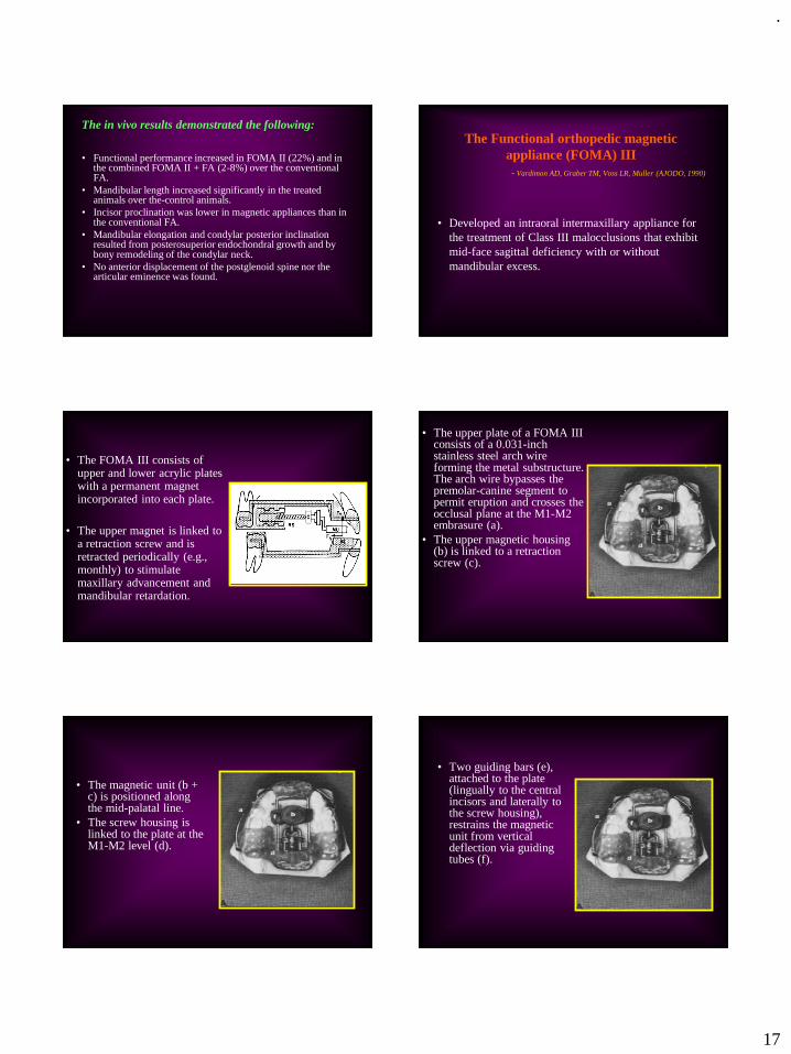
.
17
The in vivo results demonstrated the following:
• Functional performance increased in FOMA II (22%) and in the combined FOMA II + FA (2-8%) over the conventional FA.
• Mandibular length increased significantly in the treated animals over the-control animals.
• Incisor proclination was lower in magnetic appliances than in the conventional FA.
• Mandibular elongation and condylar posterior inclination resulted from posterosuperior endochondral growth and by bony remodeling of the condylar neck.
• No anterior displacement of the postglenoid spine nor the articular eminence was found.
97
The Functional orthopedic magnetic
appliance (FOMA) III
- Vardimon AD, Graber TM, Voss LR, Muller (AJODO, 1990)
• Developed an intraoral intermaxillary appliance for
the treatment of Class III malocclusions that exhibit
mid-face sagittal deficiency with or without
mandibular excess.
98
• The FOMA III consists of upper and lower acrylic plates with a permanent magnet incorporated into each plate.
• The upper magnet is linked to a retraction screw and is retracted periodically (e.g., monthly) to stimulate maxillary advancement and mandibular retardation.
99
• The upper plate of a FOMA III consists of a 0.031-inch stainless steel arch wire forming the metal substructure. The arch wire bypasses the premolar-canine segment to permit eruption and crosses the occlusal plane at the M1-M2 embrasure (a).
• The upper magnetic housing (b) is linked to a retraction screw (c).
100
• The magnetic unit (b + c) is positioned along the mid-palatal line.
• The screw housing is linked to the plate at the M1-M2 level (d).
101
• Two guiding bars (e), attached to the plate (lingually to the central incisors and laterally to the screw housing), restrains the magnetic unit from vertical deflection via guiding tubes (f).
102
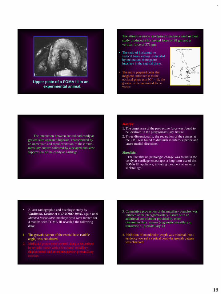
.
18
Upper plate of a FOMA III in an
experimental animal.
103
The attractive mode neodymium magnets used in their
study produced a horizontal force of 98 gm and a
vertical force of 371 gm.
• The ratio of horizontal to vertical force vectors is dictated by inclination of magnetic interface in the sagittal plane.
• The more perpendicular the magnetic interface is to the occlusal plane (sin 90° = 1), the greater is the horizontal force vector.
104
The interaction between sutural and condylar
growth sites appeared biphasic, characterized by
an immediate and rapid excitation of the circum-
maxillary sutures followed by a delayed and slow
suppression of the condylar cartilage.
105
Maxilla:
1. The target area of the protractive force was found to be localized in the pterygomaxillary fissure.
2. Three dimensionally, the separation of the sutures at the PMF was found to diminish in infero-superior and latero-medial directions.
Mandible:
The fact that no pathologic change was found in the condylar cartilage encourages a long-term use of the FOMA III appliance, initiating treatment at an early skeletal age.
106
• A later radiographic and histologic study by
Vardimon, Graber et al (AJODO 1994), again on 9
Macaca fascicularis monkeys who were treated for
4 months with FOMA III revealed the following
data:
1. The growth pattern of the cranial base (saddle
angle) was not altered.
2. Midfacial protraction occured along a recumbent
hyperbolic curve with a horizontal maxillary
displacement and an anterosuperior premaxillary
rotation.
107
3. Cumulative protraction of the maxillary complex was initiated at the pterygomaxillary fissure with an additional contribution provided by other circummaxillary sutures (zygomaticomaxillary s., transverse s., premaxillary s.)
4. Inhibition of mandibular length was minimal, but a tendency toward a vertical condylar growth pattern was observed.
108

.
19
Root resorption
109
Determinants controlling iatrogenic
external root resorption and repair
during and after palatal expansion.- Vardimon, Graber, Voss, Lenke (AO, 1991)
• In this study, the mechanisms controlling external root resorption (ERR) and repair were studied on 8 Macaca fascicularis monkeys.
• The animals were treated with jackscrew, magnetic and sham palatal expansion screws. They were divided into short- and long-term groups.
110
• SEM morphometric analysis found major evidence of
ERR in the tooth-borne jackscrew appliance, in the
long-term group, in the maxillary premolars, on the
buccal and furcation root surfaces, on the mesio-
buccal root and in the apical zone.
• Correspondingly, the ERR mechanism is controlled
by impulse (F. Δt) and the critical barrier of the PDL
as primary determinants and by the environment
density as the secondary determinant.
111
• ERR is initially regulated by the force component
of the impulse and, with increased duration, by the
time component.
• The impairment/repair dynamics were found to be
dominated by 3 principles: ERR level of
irreversibility, delayed resorption response and
jiggling.
112
Results
1. Teeth
- Multirooted teeth were
substantially more
susceptible to ERR than
single rooted teeth
113
2. Surfaces
- The buccal root surface
and the furcation surface
showed distinguishable
ERR destruction
114
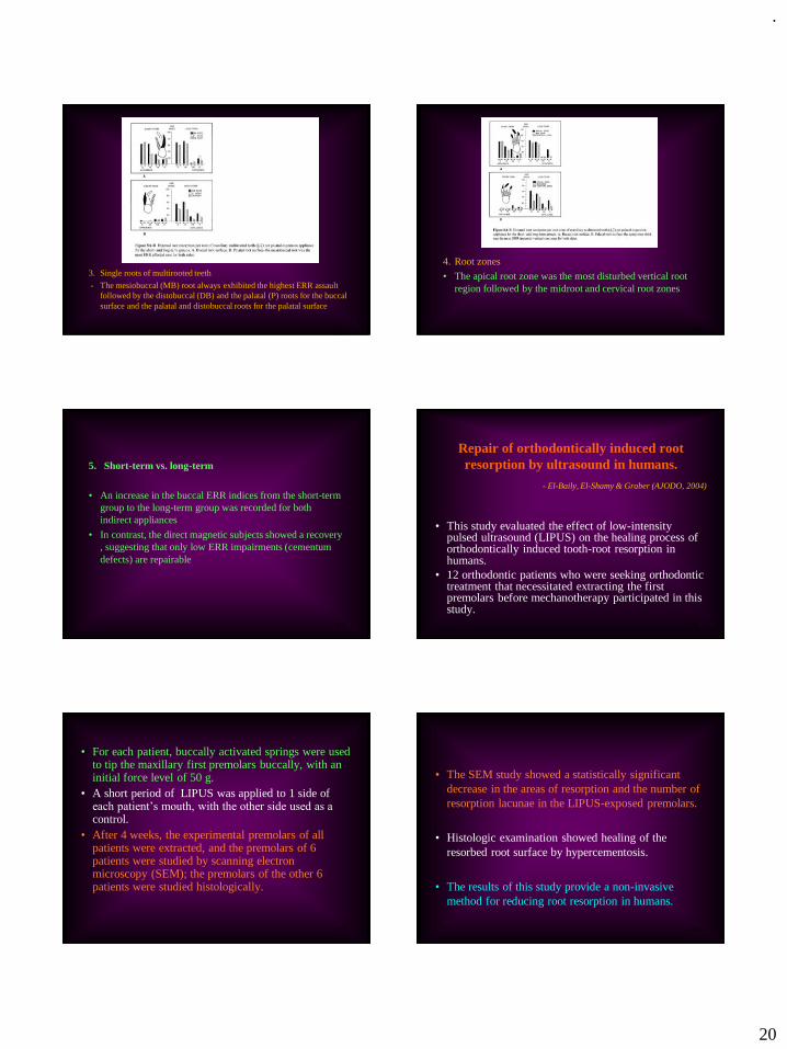
.
20
3. Single roots of multirooted teeth
- The mesiobuccal (MB) root always exhibited the highest ERR assault
followed by the distobuccal (DB) and the palatal (P) roots for the buccal
surface and the palatal and distobuccal roots for the palatal surface
115
4. Root zones
• The apical root zone was the most disturbed vertical root
region followed by the midroot and cervical root zones
116
5. Short-term vs. long-term
• An increase in the buccal ERR indices from the short-term
group to the long-term group was recorded for both
indirect appliances
• In contrast, the direct magnetic subjects showed a recovery
, suggesting that only low ERR impairments (cementum
defects) are repairable
117
Repair of orthodontically induced root
resorption by ultrasound in humans.
- El-Baily, El-Shamy & Graber (AJODO, 2004)
• This study evaluated the effect of low-intensity pulsed ultrasound (LIPUS) on the healing process of orthodontically induced tooth-root resorption in humans.
• 12 orthodontic patients who were seeking orthodontic treatment that necessitated extracting the first premolars before mechanotherapy participated in this study.
118
• For each patient, buccally activated springs were used to tip the maxillary first premolars buccally, with an initial force level of 50 g.
• A short period of LIPUS was applied to 1 side of each patient’s mouth, with the other side used as a control.
• After 4 weeks, the experimental premolars of all patients were extracted, and the premolars of 6 patients were studied by scanning electron microscopy (SEM); the premolars of the other 6 patients were studied histologically.
119
• The SEM study showed a statistically significant
decrease in the areas of resorption and the number of
resorption lacunae in the LIPUS-exposed premolars.
• Histologic examination showed healing of the
resorbed root surface by hypercementosis.
• The results of this study provide a non-invasive
method for reducing root resorption in humans.
120

.
21
Repair process of external root resorption
subsequent to palatal expansion treatment.
- Vardimon, Graber & Pitaru (AJODO, 1993)
• The repair process of external root resorption (ERR) and the role of retention mechanics in enhancing ERR repair were studied on eight Macaca fascicularismonkeys that were divided equally into short- and long-term groups. 6 monkeys received palatal expansion appliances, and 2 received sham appliances.
121
• The short-term group received active treatment.
• The long-term group received additional retention (4
months) and relapse (2 months) treatment periods
with biweekly injections of individual vital dye per
phase, i.e., procion red H-8B and violet H-3R (80
mg/kg B.W.), respectively.
122
Their results showed that:
• The short-term group demonstrated penetrated resorption with pulp exposure at sites with initial deficiency of the protecting odontoblastic layer (apical zone, nutrition canal).
• The long-term group showed two forms of ERR repair:
(1) Nonfunctional retarded repair cementum, comprised of overlapped incremental lines and deprived of extrinsic fibers, was delineated in severe pulp exposure.
123
The pulp/dentin complex showed intense incorporation
of procion dye in the dentinal tubuli, conceivably
related to a defense response in the form of sclerotic
dentin.
(2) Functional rapid repair cementum, comprised of
discriminated incremental lines mainly of mixed
cellular cementum, with a consistent pattern of five
sequential phases: the lag phase (14 to 28 days), the
incipient phase (14 days), the peak phase (14 to 28
days), the steady phase (42 to 56 days) and the
retreating phase (70 days).
124
Sharpey's fibers at functional ERR sites were scarce, never emerging from the dentinocemental junction, and not developing into principal fibers.
The pulp/dentin complex showed an increase in pulp stones but no formation of tertiary dentin. The apical area responded by hypercementosis in the form of apical occlusion and a displaced pulp canal.
125
Other contributions
126

.
22
A cephalometric analysis of the
developmental pattern and facial
morphology in cleft palate.
- T.M. Graber (AO, 1949)
• 33 cleft palate patients (22 males, 11 females) were studied cephalometrically.
It was found that:
• The maxilla in CLP cases is deficient in antero-posterior, lateral, as well as vertical growth.
127
• There is an abnormally large contribution of upper face height to total face height when the teeth are in occlusion, due to vertical maxillary deficiency.
• There is markedly larger inter-maxillary clearance or freeway space in CP individuals when compared to normals. This suggests that while there is a bony insufficiency, the general musculature attempts to maintain a normal developmental pattern and relation of parts.
• Mandibular growth on the whole appears normal. Values taken with the teeth in occlusion indicate overclosure.
128
• There is excessive lingual axial inclination of the lower incisors to the mandibular plane.
• The maxillary 1st molar tends towards a distal position with reference to craniometric measurements outside the maxilla.
• Surgical correction can limit the growth potential of the maxillary denture.
• The clinical results of orthodontic treatment, while improving the tooth to tooth relationship in some cases, does not necessarily stimulate basal bone development. Therapeutic results are often unstable and have to be maintained indefinitely.
129
A functional study of the palatal and
pharyngeal structures.
- Graber, Bzoch, Aoba (AO, 1959)
• Using high speed roentgenographic equipment, the
soft tissue morphology of normal subjects was
studied during the instant of production of various
consonant sounds (p, b, f, w, m).
• Biometric analysis was made.
130
Following conclusions were drawn:
• Soft palate increases significantly in length from the
rest to functional position.
• The greatest extent of the upward and backward
movement of the palate takes place at the midpoint of
the posterior superior surface of the palate
(mean=16mm.).
• The velopharyngeal valve is consistently closed for
all the consonant sounds during normal speech
production.
131
• Slight anterior movement of the posterior
pharyngeal wall is seen in 50% of normal cases.
The authors concluded that the orthodontist, as well
as the prosthodontist and speech therapist, should
profit from a better appreciation of normal speech
physiology.
132

.
23
Postmortems in post-treatment
adjustment.
- T.M. Graber (AJO, 1966)
• In this classic article, Dr. Graber stresses the need for a
longer period of orthodontic management in many cases.
• He says that, with the orthodontists’ dependence on
pattern and growth and development, it is essential to
keep patients under observation longer and observe the
status of the stomatognathic system in its biologic
continuum.
133
Orthosurgical teamwork.
- Olson, Mincey & Graber (JADA, 1975)
• Using the examples of 6 patients with different malocclusions, the authors have reported on the combined orthodontic-surgical approach towards treatment.
• They state that surgery and orthodontics can separately, but surely better in combination, correct a variety of developmental jaw deformities, whether they are hereditory or traumatic in origin.
134
• The patient is best served by this teamwork, not only during the actual mechanical and operative phases, but also during the initial diagnostic and treatment planning phases, which are every bit as important.
• Proper diagnosis requires a thorough knowledge of growth and development, of cephalometric analysis, of occlusion and proper jaw relationships, and of surgical and orthodontic techniques to correct these deformities.
• Here, the orthodontist, because of his training and experience in these aspects, can be invaluable to the surgeon.
135 136
• A series of orthognathic cases illustrates the
potential service that is available to the young and
the adult patient.
• Patients have problems that are not within the
therapeutic possibilities of the orthodontist alone.
• Surgical procedures in combination with
orthodontics and prosthetics, have now achieved a
level of sophistication that permits correction of
almost any type of the facial deformity quickly,
with minimum pain, and relative few unfavorable
sequelae
137
Post-pharyngeal lymphoid tissue in
Angle Class I and Class II malocclusions.
- Sosa, Graber & Muller (AJO, 1982)
• Studied the relationship between the adenoid tissue and type of malocclusion.
• Xeroradiographic lateral cephalograms were made of 80 Class I and 64 Class II/1 malocclusions.
• The epipharyngeal lymphoid tissue, nasopharyngeal airway, nasopharynx and certain cephalometric landmarks were measured.
138

.
24
Their results showed that:
• There is no clear-cut relationship between either Class I or Class II/1 malocclusions and the total nasopharyngeal area.
• Sexual dimorphism was seen:
- Class I males: widening of antero-posterior dimension of nasopharynx is associated with anterior rotation of the mandible, longer maxillas, larger SNB angles, opening of cranial base angle, and increased distance from sella to PNS. Thus, these patients have more anteriorly positioned maxilla and mandible.
139
- No association was present at all for Class II/1
males.
- Class II/1 females: larger nasopharyngeal area is
associated with longer maxillae and smaller
palatal plane angles, and anterior rotation of
mandible.
140
Orthodontics and temporomandibular
disorder: A meta-analysis.
- Kim, Graber & Viana (AJODO, 2002)
• In this meta-analysis, the relationship between traditional orthodontic treatment, including the specific type of appliance used and whether extractions were performed, and the prevalence of temporomandibular disorders (TMD) was investigated.
• Their data indicated that traditional orthodontic treatment did not increase the prevalence of TMD.
141
CONCLUSION
142
Dr. Thomas M. Graber was certainly a pioneer
amongst men. His complete devotion and love for the
specialty of orthodontics is reflected in his extensive
works on a myriad of topics, spanning over a period
of nearly six decades.
143
• As Dr. Graber’s family friend and colleague Dr. Jim McNamara noted, “Tom’s energy and enthusiasm for our profession make him a wonderful role model for future generations of orthodontists.”
• The passing of Dr. Thomas M. Graber marks the end of an era in orthodontics.
144

.
25
EVEN WHEN STARS DIE, THEIR GLOW
PERSISTS …
145 146
147
REFERENCES
1. Alexander D. Vardimon AD, Graber TM, Drescher D, Bourauel C. Rare earth magnets and impaction. Am J Orthod Dentofac Orthop. 1991; 100: 494-512.
2. Ahmad KA, Drummond JL, Graber TM, BeGole E. Magnetic strength and corrosion of rare earth magnets. Am J Orthod Dentofacial Orthop 2006;130:275 e11-15.
3. Vardimon AD, Graber TM, Voss LR, Verrusio E. Magnetic versus mechanical expansion with different force thresholds and points of application. Am J Orthod Dentofacial Orthop 1987;92: 455-66.
4. Vardimon AD, Graber TM, Drescher D, Bourauel C. Rare earth magnets and impaction. Am J Orthod Dentofacial Orthop 1991; 100:494-512.
5. Graber TM. Ch. 4 - Current status of magnetic forces in orthodontics (Biomechanics in clinical orthodontics) W.B. Saunders Co. 1997.
6. Vardimon AD, Stutzmann JJ, Graber TM, Voss LR, Petrovic AG. Functional orthopedic magnetic appliance (FOMA) II-Modus operandi. Am J Orthod Dentofac Orthop 1989;95:371-87.
148
7. Vardimon AD, Graber TM, Voss LR, Muller TP. Functional orthopedic magnetic appliance (FOMA) III-Modus operandi. Am J Orthod Dentofac Orthop.1990; 97(2): 135-48.
8. Vardimon AD, Graber TM, Stutzman J, Voss L, Petrovic AG. Reaction of the pterygomaxillary fissure and the condylar cartilage to intermaxillary Class III magnetic mechanics. Am J Orthod Dentofac Orthop 1994;105:401-13.
9. Graber TM. Notes and comments. Dental Abstracts 1976; 21(12): 712-13.
10. Vardimon AD, Graber TM, Voss LR. Stability of magnetic vs. mechanical palatal expansion. Eur. J Orthod. 1989; 11(2): 107-15.
11. Graber TM. Normal occlusion. Dent Clin North Am. 1968; Jul.: 273-90.
12. Owen D, Graber TM. The developing occlusion – orthodontic considerations for the handicapped. Dent Clin North Am. 1974; 18(3): 711-21.
13. Olson RE, Mincey DL, Graber TM. Orthosurgical teamwork. J Am Dent Assoc. 1975; 90: 998-1011.
14. Graber TM. The role of upper second molar extraction in orthodontic treatment.Am J Orthod. 1955; 41: 354-361.
15. Graber TM. Maxillary second molar extraction in Class II malocclusion. Am J Orthod. 1969; 56(4): 331-53.
149
16. Graber TM. Extraoral force – facts and fallacies. Am J Orthod. 1955;
41: 490-505.
17. Graber TM. Postmortems in post-treatment adjustment. Am J Orthod.
1966; 52(5): 331-52.
18. Graber TM. Serial extraction: A continuous diagnostic and decisional
process. Am J Orthod. 1971; 60(6): 541-75.
19. Graber TM, Chung DDB, Aoba JT. Dentofacial orthopedics vs. orthodontics. J Am Dent Assoc. 1967; 75: 1145-66.
20. Mills CM, Holman RG, Graber TM. Heavy intermittent cervical traction in Class II treatment: A longitudinal cephalometric assessment. Am J Orthod. 1978; 74(4): 361-79.
21. Graber TM. Pride in orthodontics. Am J Orthod Dentofac Orthop. 2000 May;117(5):618-20.
22. El-Bialy T, El-Shamy I, Graber TM. Growth modification of the rabbit mandible using therapeutic ultrasound: is it possible to enhance functional appliance results? Angle Orthod. 2003; 73:631–639.
23. Graber TM, Bzoch KR, Aoba T. A functional study of the palatal and pharyngeal structures. Angle Orthod. 1959; 29(1): 30-40.
150
• 24. Graber TM. A cephalometric analysis of the developmental pattern and facial morphology in cleft palate. Angle Orthod. 1949; 19(2): 91-100.
25. Kim JH, Viana MAG, Graber TM, Omerza FF, BeGole EA. The effectiveness of protraction face mask therapy: A meta-analysis. Am J Orthod Dentofac Orthop 1999;115:675-85.
26. Deguchi T, Kuroda T, Minoshima Y, Graber TM. Craniofacial features of patients with Class III abnormalities: Growth-related changes and effects of short-term and long-term chincup therapy. Am J Orthod Dentofacial Orthop 2002;121:84-92
27. Deguchi T, Kuroda T, Hunt NP, Graber TM. Long-term application of
chincup force alters the morphology of the dolichofacial Class III
mandible. Am J Orthod Dentofacial Orthop 1999;116:610-5.
28. Kim MR, Graber TM, Viana MA. Orthodontics and temporomandibular
disorder: A meta-analysis. Am J Orthod Dentofacial Orthop
2002;121:438–46.

.
26
151
29. Vardimon AD, Graber TM, Voss LR, Lenke J. Determinants controlling iatrogenic
external root resorption and repair during and after palatal expansion.
Angle Orthod. 1991; 61(2): 113-22.
30. El-Bialy T, El-Shamy I, Graber TM. Repair of orthodontically induced root
resorption by ultrasound in humans. Am J Orthod Dentofacial Orthop
2004;126:186-93.
31. Vardimon AD, Graber TM, Pitaru S. Repair process of external root resorption subsequent to palatal expansion treatment. Am J Orthod Dentofac Orthop 1993;103:120-30.
32. Graber TM. The “three M’s”: Muscles, malformation and malocclusion. Am J Orthod. 1963; 49(6): 418-50.
152
• Graber TM. Occlusal splints (Letter to Editor). J Am Dent Assoc. 1980; 100: 171a.
• Graber TM. Books for the dentist. J Am Dent Assoc. 1974; 88: 1322-42.
• Graber TM. On thumbsucking (Letter to Editor). J Am Dent Assoc. 1970; 81: 805.
• Graber TM. An orthodontic perspective after 75 years. Am J Orthod. 1976; 69(5): 572-83.
• Graber TM. Auxiliary personnel – pillars of practice procedure. Am J Orthod. 1965; 51(6): 412-36.

.
1
DIGITAL IMAGING INORTHODONTICS
Presented by: Dr. Naveen Sharma
.
.
DR.ASHWIN GEORGE, M.D.S, Dip N.B,
RAGAS DENTAL COLLEGE,
CHENNAI
Normal X-ray Digital X-ray
Silver halide grains in x-ray
films perceived as different
shades of gray by the
human eye due to varying
densities
Silver halide grains are
replaced by small light-
sensitive electronic
sensors which produce an
electric signal depending
on the voltage recorded
by the sensor
(this analog electronic signal is converted into a digital signal by a capture
card [frame grabber] and represented by shades of gray ranging from
values 0 to 255)
PRINCIPLES OF DIGITAL IMAGING
CONVENTIONAL(ANALOG)
DIGITAL
CEPHALOGRAM
CONVENTIONAL DIGITAL
OPG INDIRECT DIRECT
a) Scanner
b) Phosphor plate
a) Charged Coupled Device (CCD)
b) Complementary metal oxide
semiconductor (CMOS)
METHODS OF IMAGE ACQUISITION

.
2
SCINTILLATOR
- converts x-radiation to photons
(light)
FIBRE OPTIC LAYER
- conducts photons to CCD
- stops x-radiation
CCD
- converts photons to electrons
(charge)
ELECTRONIC CIRCUIT
- amplifies the signal
- converts the analog signal to digital
DIGITAL IMAGING THROUGH CCD
✓ Dose reduction
✓ Image prediction
✓ Reduced overall time
✓ Measurements [Digital Calipers]
✓ 3-D Reconstruction
✓ Contrast enhancement
✓ Storage
✓ Teleradiology
✓ Environmentally Friendly
DISADVANTAGES
► Cost
► Reduced Sensor Dimension
► Cross-Infection Control
ADVANTAGES
DIGITAL IMAGING
There are five basic techniques for producing
digital models:
1) Stereophotogrammetry
2) Laser scanning
3) Destructive imaging
4) White light scanning
5) CT scanningStereo pairs of images are captured from two converging
cameras and three dimensional reconstruction occurs in
only those areas that are visible to both cameras
A new Laser scan based approach callede-models was developed to improve the accuracy and efficiency of orthodontic diagnosis, treatment planning, and bracket placement.
➢ Pointing and clicking with the mouse can easily measure Bolton
discrepancies and arch length tooth size discrepancies.
USES
Using the e-model software,
the clinician can move, rotate,
or zoom in on the model and
make measurements in any
plane or orientation.
DIGITAL MODELS
The orthodontist sends the impression and bite registration to
GeoDigm/OrthoCAD. E-models are constructed through proprietary laser
scanning process
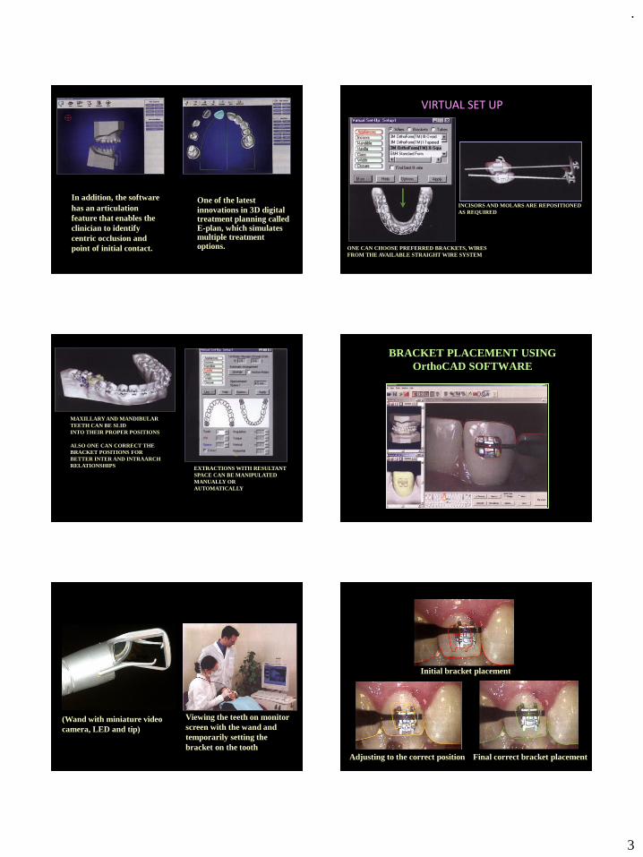
.
3
One of the latest
innovations in 3D digital treatment planning called E-plan, which simulates multiple treatment options.
In addition, the software
has an articulation
feature that enables the
clinician to identify
centric occlusion and
point of initial contact. ONE CAN CHOOSE PREFERRED BRACKETS, WIRES
FROM THE AVAILABLE STRAIGHT WIRE SYSTEM
INCISORS AND MOLARS ARE REPOSITIONED
AS REQUIRED
VIRTUAL SET UP
MAXILLARY AND MANDIBULAR
TEETH CAN BE SLID
INTO THEIR PROPER POSITIONS
ALSO ONE CAN CORRECT THE
BRACKET POSITIONS FOR
BETTER INTER AND INTRAARCH
RELATIONSHIPS EXTRACTIONS WITH RESULTANT
SPACE CAN BE MANIPULATED
MANUALLY OR
AUTOMATICALLY
BRACKET PLACEMENT USING
OrthoCAD SOFTWARE
(Wand with miniature video
camera, LED and tip)
Viewing the teeth on monitor
screen with the wand and
temporarily setting the
bracket on the tooth
Initial bracket placement
Adjusting to the correct position Final correct bracket placement
ORTHOCAD BRACKET PLACEMENT

.
4
ADVANTAGES OF ORTHOCAD BRACKET PLACEMENT
1) Consistent, accurate bracket placement
2) Expresses the full potential of the appliance
3) Yields better treatment outcome
4) Shorter treatment time
5) Allows to compare multiple treatment scenarios"virtual bracket placement"
and selection of the
arch wire sequence and progression
Wire bending robot
Producing arch wires
OraScanner -a light-based
imaging device Diagnosis and
treatment planning
Obtaining a
Virtual model
SURE SMILE TECHNOLOGY
PRETREATMENT RADIOGRAPHS
AND IMPRESSIONS SENT TO
INVISALIGN LABORATORIES
IMPRESSIONS ARE CONVERTED
TO PLASTER MODELS AND
CHECKED FOR QUALITY
INVISALIGNERS
MODELS ARE COATED WITH
PROTECTIVE
SHELLS AND ENCASED IN A MIXTURE
OF RESIN AND HARDENER
AFTER CHEMICAL CURING, BLOCKS OF
HARDENED RESIN WITH PLASTER
MODELS ARE OBTAINED
EACH TRAY IS PLACED IN A
DESTRUCTIVE SCANNING
MACHINE
STEREO LITHOGRAPHIC
MACHINE
INVISALIGN CUTTERTRIMMING
OF INVISALIGN
DESTRUCTIVE
SCANNING
GENERATED 3-D
MODEL
Use of INVISALIGN appliance
in the treatment of moderate crowding

.
5
ADVANTAGES OF INVISALIGN➢ Improved esthetics
➢ Ability to remove the appliance
DISADVANTAGES➢ All permanent teeth should be fully erupted
➢ It does not allow for continued eruption of teeth or dental arch
changes during growth
➢ Major restorative work should be performed before the
commencement of treatment
➢ Treatment plan cannot be changed once the appliance series has
begun
➢ Only crown position is displayed in the computer
➢ Inability to integrate hard and soft tissues
➢ It is expensive
COMPUTERIZED SURGICAL
PREDICTION IMAGING
“A useful indicator of
potential treatment
outcomes with different
techniques & the
orthodontist’s ability to
achieve them”
The software superimposes the patients lateral
photograph onto the lateral cephalogram to a proportionate
scale.
When the computerized predictions are made, the
patient can now have an idea of his / her probable facial
appearance after the planned treatment.
Pre treatment Computer prediction
VIDEO IMAGING & PREDICTION ADVANTAGES
→ Stored in computer memory
and recalled easily
→ Several alternative
predictions possible much more
rapidly
→ Enhancement of the doctor-
patient communication
→ Promotes greater
understanding and satisfaction
with the outcome, as long as the
patient recognizes that the
DISADVANTAGES
→ Software design
dependent and technique
sensitive
→ Expensive
→ Poor soft tissue
definition in particular
areas
Prediction is only a goal and not a guarantee
Pt –A Age: 24/M
Diagnosis: Skeletal Class III
Hypoplastic Maxilla and Prognathic Mandible
Pre-Treatment Profile

.
6
Pre-Surgical after Dentoalveolar Decompensation
Manual Prediction
(Cut and Paste Method) Maxillary Advancement – 4 mm
Mandibular setback - 4mm
Soft tissue changes associated with
treatment
MAXILLARY ADVANCEMENT
Nose : Slight elevation of tip
Base of upper Lip : protracted by 1 mm
Upper Lip : protracted by 2.8 mm
and shortens by 1.5 mm
MANDIBULAR SETBACK:
Chin retracted by 4 mm
Lower Lip by 2.8 mm
Pre-Surgical
Manual Superimposition
Comparison between Manual and Computerized Prediction
Pre Surgical
Computer Superimposition
Computer SuperimpositionManual Superimposition
•1•2
•3
•4
•5
•1•2•3
•4
•5
C:\ss.pat
Pre- Surgical Computer Prediction Actual Post
Treatment
DENTOFACIAL PLANNER
PLUSDFP WINDOWS 98 Platform
DOLPHIN IMAGING DI WINDOWS 98,2000,XP
Platform
QUICK CEPH SYSTEM QC MACINTOSH Platform
VISTA DENT GAC WINDOWS XP Pro
PRACTICE WORKS OTP WINDOWS
COMPARISION OF CURRENT PREDICTION IMAGING
PROGRAMS
5 programs with the largest market share was chosen
J.Dempsey Smith and Paul M. Thomas, AJO May 2004
Case No:1 Short Face Patient (Actual and Predicted Outcomes)
Surgery Done – Mandibular Advancement

.
7
Case No:2 Long Face Patient (Actual and Predicted Outcomes)
Surgery done - Maxillary impaction and mandibular set back RESULTS
Dentofacial planner ( DFP) was the clear favorite
in both observer group [short face and long face]
Dolphin imaging (DI) and Quick ceph (QC) were the
next favorites with DI handling long face subjects
better and QC more competent with the short face
group
For GAC and OTP- both consistently rated poor
regardless of facial type
J.Dempsey Smith and Paul M. Thomas, AJO May 2004
PREDICTION IMAGING PROGRAMS
1) Prescription Planner/Portrait software system (PP)
2) Orthognathic Treatment Planner (OTP)
3) Dentofacial planner (DFP)
4) Quick Ceph (QC)
5) Dolphin Imaging (DI)
6) Vistadent (GAC)
7) Orthognathic Prediction Analysis (OPAL)
8) Nemoceph
9) Dr.Ceph
THREE DIMENSIONAL IMAGE CAPTURING SYSTEM
FOR FACIAL PROFILES (C3D software)
The analog picture of a stereopair of video cameras
are converted into a digital mode with a standard frame
grabber (A device for converting a television picture to a digital
array of numbers). The software does the entire capture in 50
milliseconds
3D imaging of the face enables the orthodontist to evaluate the face from any
direction. Here, a skeletal Class III case is displayed in different views

.
8
Applications of CT and MRI
in orthodontics
Equipment-
Gantry – houses the patient. Patient is surrounded by magnetic coils
Magnetic Resonance Imaging
Magnetic fields are caused by rotating electric charges.
Essentially it is the- imaging of the water in the tissue.
Images are generated from protons of the hydrogen nuclei of water.
Indications of MRI✓ MRI imaging of TMJ
✓ Cleft lip and palate
✓ Tonsillitis and adenoiditis, optimum assessment of upper airway
✓ Cysts, infections and tumors
Contraindications
Patients with cardiac pacemakers.
Patients with cerebral metallic aneurysm clips.- Slight
movement of the clip could produce bleeding
Stainless steel and other metals produce artifacts ; obliterate
image details of the facial area.
✓ Determine the structural relationship between the Condyle,
Articular disc and Glenoid fossa
✓ Detect inflammation, hematoma and effusion for the soft tissue
components
Importance of MRI imaging of the TMJ
Short comings Inability to identify ligament tears or perforations
Dynamics of tissue joint not possible
Cannot be used in patients suffering from
claustrophobia
In a single scan, the x-ray source and a reciprocating x-ray sensor rotate around the patient's head and acquires 360 pictures in 17 seconds of exposure time.
The entire maxillofacial volume(13 cm-diameter field of view) isenlarged, and the patientreceives an absorbed dosesimilar to a peri apical survey ofthe dentition.
NewTom QR 9000 CT Scanner

.
9
The 360 acquired images
undergo a primary
reconstruction to
mathematically replicate the
patient's anatomy into a single
3D volume.
Applications
Location of impacted tooth
relative to roots of adjacent
teeth
ADVANTAGES OF DIGITAL IMAGING IN
DIAGNOSIS AND MANAGEMENT OF
IMPACTED TEETH
Conventional radiography is by far the standard method for
viewing impacted canine but it has following short comings,
➢ Difficulty in assessing position (buccal/palatal)
➢ Difficulty in assessing level and extent of resorption of
adjacent teeth
IO - Xray OPG Occlusal View
IMPACTED MAXILLARY CANINE
COMPUTERIZED TOMOGRAPHYPERIAPICAL
RADIOGRAPH
Tomogram of the head
showing the cutting
direction of the beam
through the anterior
part of the maxilla
perpendicular to the
long axis of the
maxillary incisors.
TECHNIQUE OF ACQUIRING CT
Slice thickness of 2mm are normally taken for assessing
the canine position
BUCCALY POSITIONED IMPACTED MAXILLARY CANINE
MAXILLARY CANINE PALATALLY POSITIONED IMPACTED

.
10
Periapical radiograph – not
showing extent of resorption
ASSESSMENT OF ROOT RESORPTION USING CT SCAN
CT scan of the same region
showing the extent of
resorption of lateral incisors
palatally
Lateral incisor after extraction;
Palatal view showing the total extent of
the resorption
DIGITAL IMAGING AND
SMILE ANALYSIS
The flaw in traditional smile
analysis has been based on the
tracing of the lateral
cephalogram, which is taken in
repose (at rest)
Due to this limitation incisor
position has been determined
from a static rather than a
dynamic record.
The orthodontist as an architect of the smile
needs to identify and quantify the elements of the smile that
needs
▪ correction,
▪ enhancement
▪ and improvement
as well as identifying the positive elements of the smile that
must be saved.
Smile Analysis with the SMILE MESH PROGRAMME
This methodology was first used manually by Hulsey and later
modified and computerized by Ackerman
The frame that best represents the patient’s social smile is selected
and saved as a JPEG file.
The smile image is then opened in a program called SmileMesh,
which measures 15 attributes of the smile
Before expansion(more of dark space on smile)
After expansion(reduced dark space after treatment)
Smile mesh analysis after RAPID MAXILLARY EXPANSION
BEFORE RME AFTER RME

.
11
RAPID PROTOTYPING
(RPT)
It is a group of manufacturing processes that enable the direct physical realization of 3D computer models. This technology converts the 3D computer data provided by a dedicated file (STL file) format directly to a physical model, layer by layer with a high degree of accuracy.
STEREOLITHOGRAPHY (SLA)
Stereolithography (SLA) is the most widely distributed process of RPT
RAPID PROTOTYPING (RPT)
APPLICATIONS :
1. Custom made brackets for individual patient anatomy of crowns.[lingual brackets]
2.Various mock surgery procedures can be practiced on the 3D Biomodels, allowing optimal input into the management decision, pre-operative planning and choice of surgical technique.
LIMITATIONS• Cost
• Radiation exposure of the patient (CT scanning)
With wider use and further technological development, these drawbacks will be minimized. The 3D SLA biomodels may in future become an adjunct to diagnosis, and treatment planning in Orthognathic surgery.
BRACKET MANUFACTURING BY RPT
Using state-of-the-art CAD/CAM technology, the two
normally separate processes of bracket production and
bracket positioning are fused into one unit.
• The brackets manufactured for lingual orthodontics is based
on digital registration of the malocclusion.
• The brackets are then individually designed and optimally
positioned in the computer using Rapid prototyping.
A silicone impression is used for preparation of a malocclusion cast and a therapeutic set-up.
• The set-up is digitized with a high-resolution 3D scanner.
• The individual brackets are generated on this surface at a computer workstation.
• First, appropriate pads are designed on the lingual surfaces of the teeth.
• The next step is optimal positioning of the bracket bodies
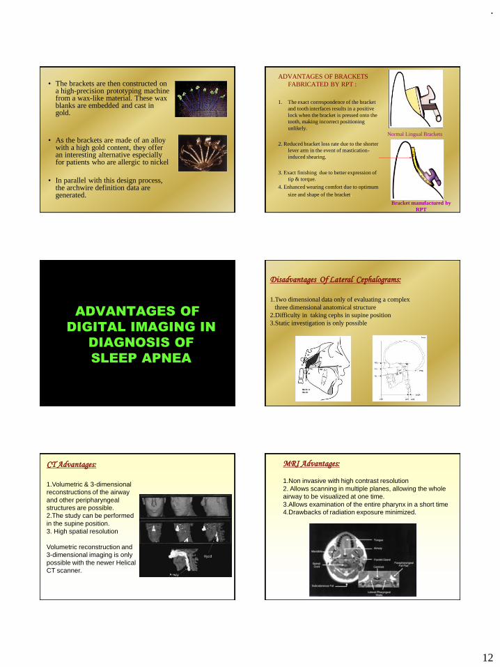
.
12
• The brackets are then constructed on a high-precision prototyping machine from a wax-like material. These wax blanks are embedded and cast in gold.
• As the brackets are made of an alloy with a high gold content, they offer an interesting alternative especially for patients who are allergic to nickel
• In parallel with this design process, the archwire definition data are generated.
ADVANTAGES OF BRACKETS
FABRICATED BY RPT :
1. The exact correspondence of the bracket
and tooth interfaces results in a positive
lock when the bracket is pressed onto the
tooth, making incorrect positioning
unlikely.
2. Reduced bracket loss rate due to the shorter
lever arm in the event of mastication-
induced shearing.
3. Exact finishing due to better expression of
tip & torque.
4. Enhanced wearing comfort due to optimum
size and shape of the bracket.
Normal Lingual Brackets
Bracket manufactured by
RPT
ADVANTAGES OF
DIGITAL IMAGING IN
DIAGNOSIS OF
SLEEP APNEA
Disadvantages Of Lateral Cephalograms:
1.Two dimensional data only of evaluating a complex
three dimensional anatomical structure
2.Difficulty in taking cephs in supine position
3.Static investigation is only possible
CT Advantages:
1.Volumetric & 3-dimensional
reconstructions of the airway
and other peripharyngeal
structures are possible.
2.The study can be performed
in the supine position.
3. High spatial resolution
Volumetric reconstruction and
3-dimensional imaging is only
possible with the newer Helical
CT scanner.
MRI Advantages:
1.Non invasive with high contrast resolution
2. Allows scanning in multiple planes, allowing the whole
airway to be visualized at one time.
3.Allows examination of the entire pharynx in a short time
4.Drawbacks of radiation exposure minimized.

.
13
A single excitation is used to obtain mid-sagittal and axial
projections during transnasal shallow respiration at rest,
simulation of snoring.
Uvula & narrowed airwayNormal upper airway
Awake position Asleep state
THE PAST IS A SOURCE OF KNOWLEDGEAND FUTURE IS A SOURCE OF HOPE.
TO LOVE THE PAST IMPLIES
A FAITH IN THE FUTURE.
AcknowledgementThe Management & Principal
Ragas Dental College & Hospital
Our team
Dr. N.R.Krishnaswamy
DR. LODD MAHENDRA
DR. VENKATESWARAN
DR. SAPNA
DR. AJIT
DR. BALAJI
&
Post Graduate students
Mr. Ashok(Graphic designer)
Thank you