![AVR - dl.melec.irdl.melec.ir/download/pdf/AVR/CodeVision-Fusebit[Melec.ir].pdf · AVR AVR AVR AVR 01 CodeVision CKSEL3..0 Device Clocking Option CKSEL3..0 External Crystal/Ceramic](https://static.fdocuments.us/doc/165x107/5cf6e10d88c99387248bfc0e/avr-dlmelecirdlmelecirdownloadpdfavrcodevision-fusebitmelecirpdf.jpg)
CAN AVR Training
28
AT90CAN128 .............................................................................................. CAN Training DVK90CAN1 & ImageCraft Platforms Rev 2.00
description
CAN AVR Training
Transcript of CAN AVR Training
DVK90CANPlR
AT90CAN128 ..............................................................................................
CAN Training
1 & ImageCraftatformsev 2.00

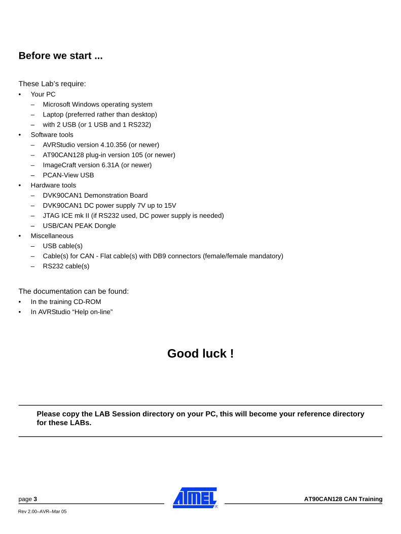
Before we start ...
These Lab’s require:• Your PC
– Microsoft Windows operating system
– Laptop (preferred rather than desktop)
– with 2 USB (or 1 USB and 1 RS232)
• Software tools
– AVRStudio version 4.10.356 (or newer)
– AT90CAN128 plug-in version 105 (or newer)
– ImageCraft version 6.31A (or newer)
– PCAN-View USB
• Hardware tools
– DVK90CAN1 Demonstration Board
– DVK90CAN1 DC power supply 7V up to 15V
– JTAG ICE mk II (if RS232 used, DC power supply is needed)
– USB/CAN PEAK Dongle
• Miscellaneous
– USB cable(s)
– Cable(s) for CAN - Flat cable(s) with DB9 connectors (female/female mandatory)
– RS232 cable(s)
The documentation can be found:• In the training CD-ROM
• In AVRStudio “Help on-line”
Good luck !
Please copy the LAB Session directory on your PC, this will become your reference directoryfor these LABs.
page 3 AT90CAN128 CAN Training
Rev 2.00–AVR–Mar 05

AT90CAN128 - CAN Training page 4
Rev 2.00–AVR–Mar 05
Lab 1: CAN_Echo
1 - INTRODUCTIONThe purpose of this “LAB” is to get all software and hardware running and to verify that everything is workingcorrectly. Once running, use few minutes to familiarize yourself with the tools, the code (lab. & library) and thehardware and try to understand how they work.
This exercise uses a fully working C code that should compile and run without further modifications.
2 - TASK 1Check your configuration ... and
2.1 - Getting Started with ImageCraft
For this guide it is required that ImageCraft ICCAVR version 6.31A (or newer) is installed on your computer. Forgetting started quickly, we will use a simple example application: «CAN_Echo».
We will:• Create a project in ImageCraft ICCAVR.• Build an object file for debugging in AVRStudio.• Build an Intel Hex file for your target part, the AT90CAN128.
2.1.1 - Creating a Project in ImageCraft ICCAVR.
Open ImageCraft ICCAVR. If you have used it before, your last project will pop up in the IDE. Close it.
Now, follow these steps for making the project «CAN_Echo».
1. Select «Project-->New».
2. Select «..\Lab_Session\CAN_Echo\» directory as your working directory and type «can_echo» -for instance - in the project name field and click «Save». ImageCraft will create «can_echo.prj» asproject description file.
3. Select «Project --> Add File(s) ...» and select:- «main_can_echo.c» main source file and click «Open»,- «.\lib_mcu\can\can_lib.c» source file and click «Open»,- «.\lib_mcu\can\can_drv.c» source file and click «Open».
4. To view a C-code file, double click on these names in the Project view window.
5. The project is completed, and the settings are saved when closing ICCAVR.
2.1.2 - Setting up Target in ImageCraft ICCAVR.
Now that you have established a working project, you also need to configure the compiler, linker etc... of theImageCraft ICCAVR to work with you, not against you.
To set what device your code will target, the compiler setting has to be made. Choose «Options» in the«Project» pull-down menu. Setup the «Target», the «Compiler» and the «Paths» tabs according toFigure 1.
Note:When building, the ICCAVR can produce either or both:- An object file (COFF) for debugging information and Flash contents,- A binary (Intel HEX) file for loading into the Flash of our AT90CAN128.
Lab 1: CAN_Echo
page 5 AT90CAN128 CAN Training
Rev 2.00–AVR–Mar 05
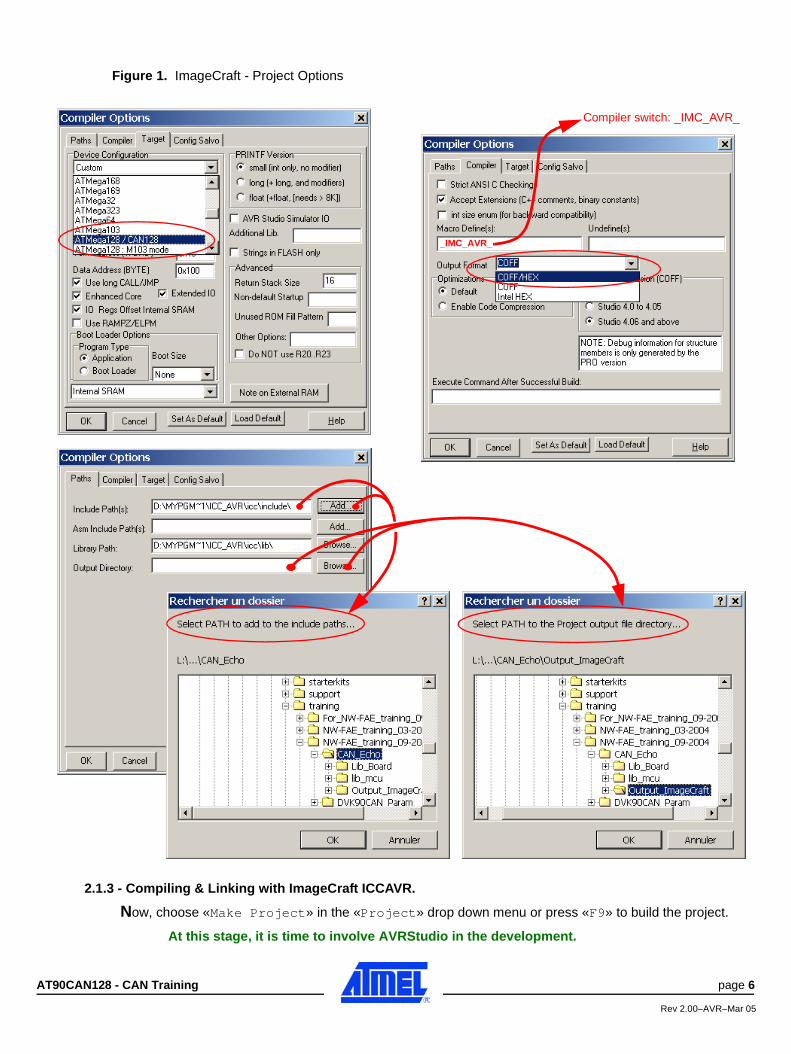
Figure 1. ImageCraft - Project Options
2.1.3 - Compiling & Linking with ImageCraft ICCAVR.
Now, choose «Make Project» in the «Project» drop down menu or press «F9» to build the project.
At this stage, it is time to involve AVRStudio in the development.
_IMC_AVR_
Compiler switch: _IMC_AVR_
AT90CAN128 - CAN Training page 6
Rev 2.00–AVR–Mar 05
2.2 - Opening the Compiled Object File in AVRStudio
AVRStudio is project based, which means that any development or debugging job is done within a projecthandling your files, AVRStudio settings and so on.
When AVRStudio is launched, the project wizard manager will pop up, and a new project can be made or oldprojects re-loaded.
1. Select «Open» and browse to the file «can_echo.cof» in your «Output_ImageCraft» directory and«Open» it,
2. Select «AVR Simulator» as debug platform and «AT90CAN128» as device,
3. Press «Finish».
4. The project is ready to be debugged in the simulator or programmed into an AVR.
5. Spend a few minutes reading and understanding the «can_echo» code.
The «can_echo» project is a CAN application that receives any CAN 2.0A frames and re-sends them formattedas 8-byte data frame with the same Identifier. The 6 first data bytes sent are the data bytes received (default byteif not exist is 0x00) and the 2 last data bytes are the content of the “CAN Time Stamp Register - CANSTMP” ofthe received message.
2.3 - AT90CAN128 Plug-in AVRStudio
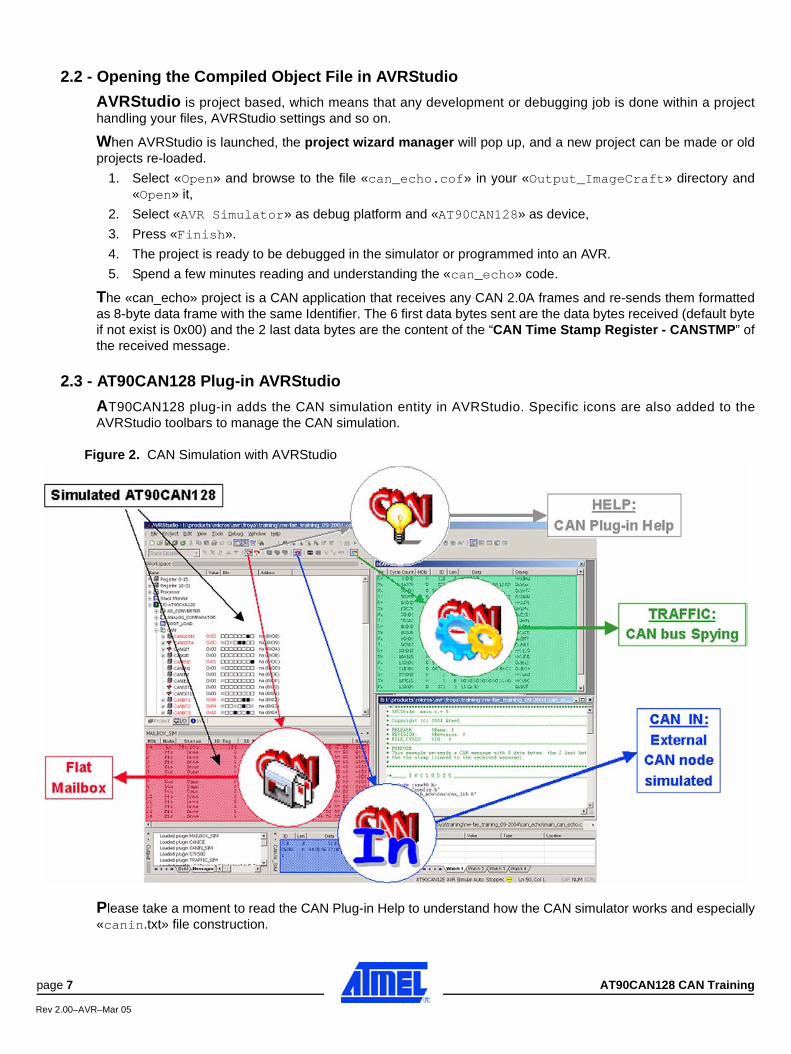
AT90CAN128 plug-in adds the CAN simulation entity in AVRStudio. Specific icons are also added to theAVRStudio toolbars to manage the CAN simulation.
Figure 2. CAN Simulation with AVRStudio
Please take a moment to read the CAN Plug-in Help to understand how the CAN simulator works and especially«canin.txt» file construction.
page 7 AT90CAN128 CAN Training
Rev 2.00–AVR–Mar 05

2.4 - CAN Simulation with AVRStudio
AT90CAN128 needs some input frames. An external CAN node is simulated playing the «canin.txt» file. TheCAN Plug-in Help gives you more information about this file function (2nd main item). It can provide periodicalframes. «can_echo» project answers to these frames sending an 8-byte frame with the same ID.
Open (in an text editor) and modify as you want the «canin.txt» file to perform a realistic external CAN nodebehavior (path = ..\Atmel\AVR Tools\AvrStudioPlugin\AT90CAN128\canin.txt).An examp le o f «can in . t x t» is g i ven in the d i rec to ry : ..\Lab_Session\CAN_Echo\ o r..\Lab_Solutions\CAN_Echo\ . You can re-copy this example.
Figure 3. «canin.txt» Example
Notes: 1.«canin.txt» is updated only entering in debug mode («Debug-->Start Debugging»).
2.«canin.txt» doesn’t belong to the project folder. Its location is:
..\Atmel\AVR Tools\AvrStudioPlugin\AT90CAN128\canin.txt
Once this file is saved, you can start the simulation:
1. Select «Debug-->Start Debugging» if the simulation is not yet started,
2. Select «Debug-->Run»,
3. Await some seconds,
4. Select «Debug-->Break»
Observe the CAN Traffic window content (if display problem occurs, click «mouse-left» to refresh the window):
Figure 4. CAN TRAFFIC Window
1. The messages can be seen as couples,- First one Rx then one Tx- Same ID, the Tx message always has “8” as length, ....
2. The last 2 bytes of a Tx message must be the stamp of the Rx message just before (initiatory message).
AT90CAN128 - CAN Training page 8
Rev 2.00–AVR–Mar 05
3. The answer to the message ID=BAD is not in conformity with what we expect !Explanation:- The input message contains a CRC error.- The CAN library doesn’t fully update the CAN descriptor message (c.f. “Annex 3: CAN Library”).- You have an example that takes into account this type of CAN error in
«..\Lab_Session\CAN_Echo_Plus» directory, .
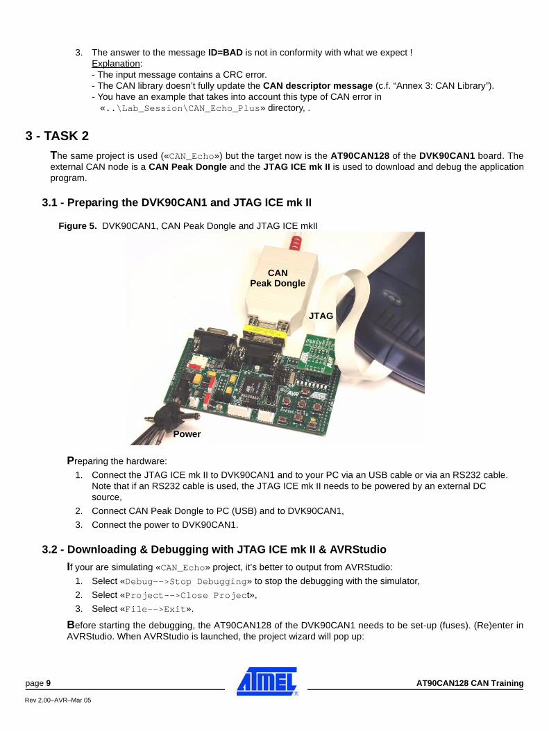
3 - TASK 2The same project is used («CAN_Echo») but the target now is the AT90CAN128 of the DVK90CAN1 board. Theexternal CAN node is a CAN Peak Dongle and the JTAG ICE mk II is used to download and debug the applicationprogram.
3.1 - Preparing the DVK90CAN1 and JTAG ICE mk II
Figure 5. DVK90CAN1, CAN Peak Dongle and JTAG ICE mkII
Preparing the hardware:
1. Connect the JTAG ICE mk II to DVK90CAN1 and to your PC via an USB cable or via an RS232 cable. Note that if an RS232 cable is used, the JTAG ICE mk II needs to be powered by an external DC source,
2. Connect CAN Peak Dongle to PC (USB) and to DVK90CAN1,
3. Connect the power to DVK90CAN1.
3.2 - Downloading & Debugging with JTAG ICE mk II & AVRStudio
If your are simulating «CAN_Echo» project, it’s better to output from AVRStudio:
1. Select «Debug-->Stop Debugging» to stop the debugging with the simulator,
2. Select «Project-->Close Project»,
3. Select «File-->Exit».
Before starting the debugging, the AT90CAN128 of the DVK90CAN1 needs to be set-up (fuses). (Re)enter inAVRStudio. When AVRStudio is launched, the project wizard will pop up:
CAN
JTAG
Power
Peak Dongle
page 9 AT90CAN128 CAN Training
Rev 2.00–AVR–Mar 05
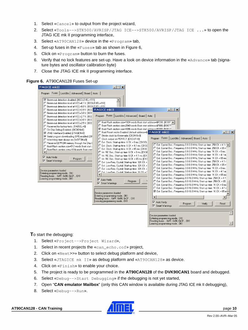
1. Select «Cancel» to output from the project wizard,
2. Select «Tools-->STK500/AVRISP/JTAG ICE-->STK500/AVRISP/JTAG ICE ...» to open the JTAG ICE mk II programming interface,
3. Select «AT90CAN128» device in the «Program» tab,
4. Set-up fuses in the «Fuses» tab as shown in Figure 6,
5. Click on «Program» button to burn the fuses.
6. Verify that no lock features are set-up. Have a look on device information in the «Advance» tab (signa-ture bytes and oscillator calibration byte)
7. Close the JTAG ICE mk II programming interface.
Figure 6. AT90CAN128 Fuses Set-up
To start the debugging:
1. Select «Project-->Project Wizard»,
1. Select in recent projects the «can_echo.cof» project,
2. Click on «Next>>» button to select debug platform and device,
3. Select «JTAGICE mk II» as debug platform and «AT90CAN128» as device.
4. Click on «Finish» to enable your choice.
5. The project is ready to be programmed in the AT90CAN128 of the DVK90CAN1 board and debugged.
6. Select «Debug-->Start Debugging» if the debugging is not yet started,
7. Open “CAN emulator Mailbox” (only this CAN window is available during JTAG ICE mk II debugging),
8. Select «Debug-->Run».
AT90CAN128 - CAN Training page 10
Rev 2.00–AVR–Mar 05

Note:At this stage, the «CAN_Echo» program is flashed. If the debugger is stopped, the program is reset andthen runs.
3.3 - CAN PEAK Dongle Set-up1. Invoke PCANView on your PC.
2. Setting PCANView,
Set «Baud rate» to 250 KBit/sec and click on «OK».
3. Select «Transmit-->New» and enter one (or more) transmit periodic message(s) (ex: period=1000ms),
3.4 - Project running controlled by JTAG ICE mk II & AVRStudio
The project is now running and it is controlled by JTAG ICE mk II. Verify the answer to the periodic message sentby the CAN PEAK Dongle. Exert yourself playing with all JTAG ICE mk II features, playing with the “CANemulator Mailbox” and the I/O view workspace of AVRStudio.
Note that a «Break» stops instantaneously the CAN peripheral and can “break off” a CAN transmission orreception leaving the CAN bus and the CAN nodes in undefined state.
page 11 AT90CAN128 CAN Training
Rev 2.00–AVR–Mar 05
4 - TASK 3The purpose of this new task looks like the «CAN_Echo» project. The new project is: «CAN_Echo_Plus»...\Lab_Session\CAN_Echo\main_can_echo_plus.c is a program more successful. It also accepts anautomatic recognition of the Baud Rate on the CAN bus (c.f. “#define CAN_BAUDRATE ...” in “config.h” file).
This exercise uses a fully working C code that should compile and run without further modifications.
4.1 - Compiling & Linking with ImageCraft
For this guide it is required that ImageCraft ICCAVR version 6.31A (or newer) is installed on your computer.
We will:• Create a project in ImageCraft ICCAVR ( ..\Lab_Session\CAN_Echo_Plus\ directory).• Build an object file for debugging in AVRStudio.• Build an Intel Hex file for your target part, the AT90CAN128.
The project is «can_echo_plus» project. Refer to «CAN_Echo» lab for the way to proceed without forgetting tocompile all the libraries used in this project.
4.2 - CAN Simulation with AVRStudio
(c.f. «CAN_Echo» Lab).
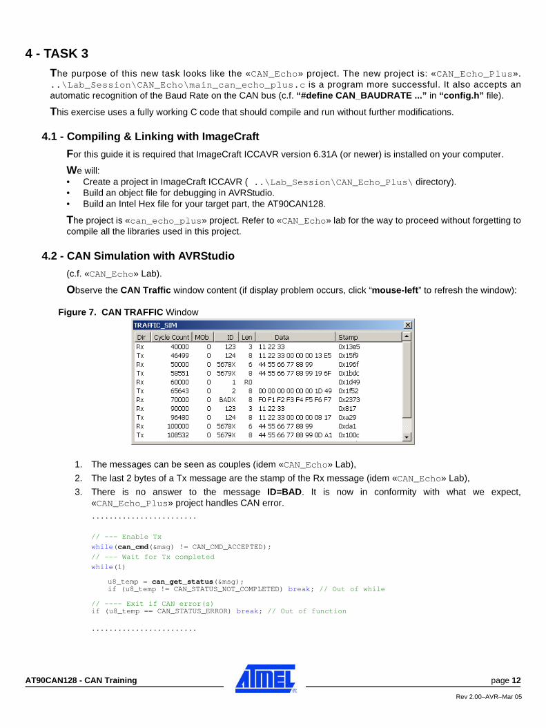
Observe the CAN Traffic window content (if display problem occurs, click “mouse-left” to refresh the window):
Figure 7. CAN TRAFFIC Window
1. The messages can be seen as couples (idem «CAN_Echo» Lab),
2. The last 2 bytes of a Tx message are the stamp of the Rx message (idem «CAN_Echo» Lab),
3. There is no answer to the message ID=BAD. It is now in conformity with what we expect,«CAN_Echo_Plus» project handles CAN error.........................
// --- Enable Tx
while(can_cmd(&msg) != CAN_CMD_ACCEPTED);
// --- Wait for Tx completed
while(1)
u8_temp = can_get_status(&msg);if (u8_temp != CAN_STATUS_NOT_COMPLETED) break; // Out of while
// ---- Exit if CAN error(s)if (u8_temp == CAN_STATUS_ERROR) break; // Out of function
........................
AT90CAN128 - CAN Training page 12
Rev 2.00–AVR–Mar 05
4.3 - Rebuilt Project to Enable «CAN_AUTOBAUD»
The goal of this phase of the project is to enable an automatic recognition of the Baud Rate on the CAN bus (c.f.“Annex 3: CAN Library”).
With ImageCraft text editor, change in “config.h” file:«#define CAN_BAUDRATE 250»
by (only playing with comment tags)
«#define CAN_BAUDRATE CAN_AUTOBAUD»
........................
//_____ D E F I N I T I O N S _______________________________________________
// -------------- MCU LIB CONFIGURATION#define FOSC 8000 // 8 MHz External cristal
#define BAUDRATE 38400 // in K bit/s
// -------------- CAN LIB CONFIGURATION
//#define CAN_BAUDRATE 250 // in kBit
#define CAN_BAUDRATE CAN_AUTOBAUD
........................
Compile and link (c.f. «CAN_Echo» Lab).
4.4 - Downloading & Debugging with JTAG ICE mk II & AVRStudio
(c.f. «CAN_Echo» Lab).
4.5 - Project Running Controlled by JTAG ICE mk II & AVRStudio
Run the «can_echo_plus» project on DVK90CAN1. Once the Power-ON, the DVK90CAN1 displays inhexadecimal the number of effective attempts of CAN Bit Timing configuration. If it displays 0xFF, the“can_init()” function didn’t succeed to find a CAN Bit Timing configuration (c.f. “Annex 3: CAN Library”).
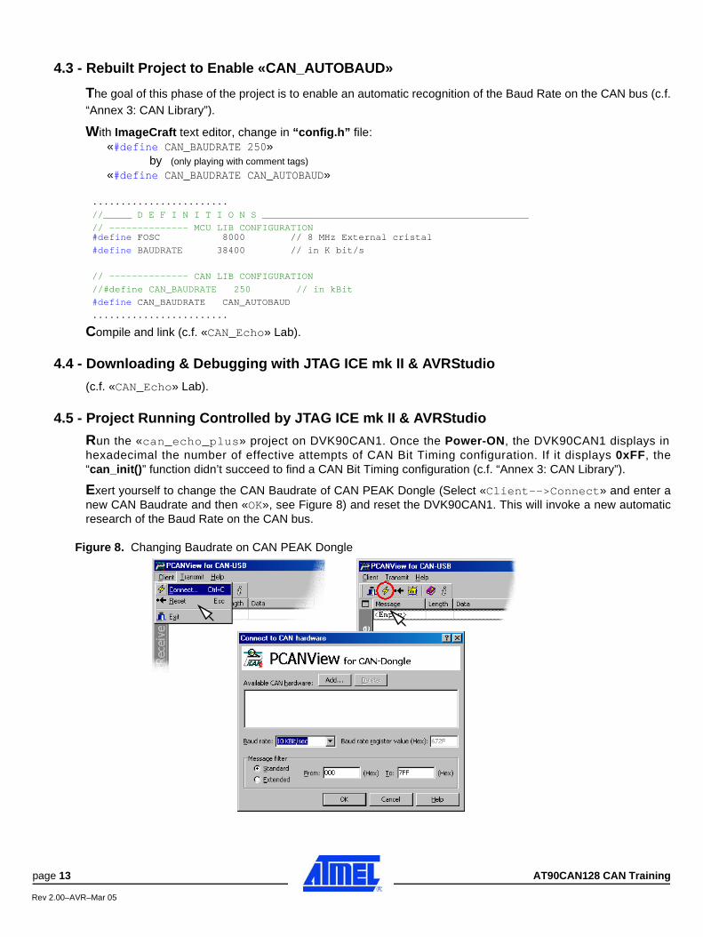
Exert yourself to change the CAN Baudrate of CAN PEAK Dongle (Select «Client-->Connect» and enter anew CAN Baudrate and then «OK», see Figure 8) and reset the DVK90CAN1. This will invoke a new automaticresearch of the Baud Rate on the CAN bus.
Figure 8. Changing Baudrate on CAN PEAK Dongle
page 13 AT90CAN128 CAN Training
Rev 2.00–AVR–Mar 05
Lab 2: DVK90CAN_Param
1 - INTRODUCTIONThe purpose of this “LAB” is to run your own application in a CAN network, understand the CAN library content andhow to use it. The trainer has the control of a CAN master node. Each trainee has to set-up and run a CAN slavenode. The trainer affects a dedicated CAN identifier (ID) to each slave node. The CAN master periodically sends arequest (CAN remote frame) to each possible node connected on the CAN bus. The slave node has to answer a dataframe with the same CAN identifier and as data, the values of the three sensors of the DVK90CAN1, i.e.temperature, luminosity and Vcc. Each answer is recorded by the CAN master node, sent to a terminal via an RS232port and displayed in the room.
This exercise uses a fully working C code that should be completed (task 1), compiled and run (task 2).
2 - TASK 1Check your configuration ... and
2.1 - File to Use
«..\Lab_Session\DVK90CAN_Param\main_dvk90can_param.c»
2.2 - Enter «MY_ID_TAG» Definition & Matching Condition
«..\Lab_Session\DVK90CAN_Param\main_dvk90can_param.c» needs to have a value for«MY_ID_TAG». The trainer gives one identifier (CAN V2.0A) number to each of DVK90CAN1. This identifier is tobe compared to the identifier of all the incoming CAN frames. Upon a matching, the slave application is ready toanswer to the CAN master.
1. Define «MY_ID_TAG»,........................
//_____ D E F I N I T I O N S ______________________________________________
#define MY_ID_TAG // ...... put your ID here ......
//_____ D E C L A R A T I O N S ____________________________________________
........................
2. Write the matching condition (refer to «can_echo.c» and «can_echo_plus.c») using the more appro-priate command,........................
// --- Reply Command
msg.ctrl.ide = 0;
msg.dlc = /* ...... put your code here ...... */ ;
msg.id.std = /* ...... put your code here ...... */ ;
msg.cmd = /* ...... put your code here ...... */ ;
//-- Enable Reply
// ...... put your code here ......
// --- Wait for Reply completed
// ...... put your code here ......
........................
3. Compile and link - intermediate version (or go to Section 2.3).
Lab 2: DVK90CAN_Param
AT90CAN128 - CAN Training page 14
Rev 2.00–AVR–Mar 05
2.3 - Introduce the Luminosity & DVK90CAN1 VCC Values in the CAN Message
The goal of «DVK90CAN_Param» project is to introduce in the CAN answer message the values of the threesensors available on the DVK90CAN1.
The first one, the room temperature, is already inserted (have a look on the type of the parameter returns by thefunction and the one to be written in the CAN descriptor buffer).
The second and the third one are the room luminosity and the Vcc value of the board.The voltage reading input can be configured either to get the board supply voltage (VCC) or the voltage of anexternal input on T11 test pin. The first configuration has been chosen - VCC.
1. Transfer the result of “get_luminosity()” ........................
// --- Prepare the data for the reply
// --- Temperature
buffer[0] = (U8)(get_temperature());
// --- Luminosity
// ...... put your code here ......
// --- VCC value
........................
2. Transfer the result of “get_vin()” (16-bit),........................
// --- VCC value (msByte first)
// ...... put your code here ......
// --- Reply Command
........................
3. Compile & link.
2.4 - S.O.S
Solution: «..\Lab_Solutions\DVK90CAN_Param\main_dvk90can_param.c»
2.5 - Compiling & Linking with ImageCraft
For this guide it is required that ImageCraft ICCAVR version 6.31A (or newer) is installed on your computer.
We will:• Create a project in ImageCraft ICCAVR ( ..\Lab_Session\DVK90CAN_Param\ directory).• Complete C source file following the directives• Build an object file for debugging in AVRStudio.• Build an Intel Hex file for your target part, the AT90CAN128.
The project is «DVK90CAN_Param» project. Refer to «CAN_Echo» Lab for the way to proceed without forgettingto compile all the libraries used in this project.
3 - TASK 2Run the «DVK90CAN_Param» project on DVK90CAN1.
Once the Power-ON, the DVK90CAN1 LEDs display the hexadecimal value of the identifier dedicated to the boardby the trainer. An acoustic acknowledge is sent after each CAN answer. You can remove it inserting «comment» inthe source (// play_ack(2);).
page 15 AT90CAN128 CAN Training
Rev 2.00–AVR–Mar 05
3.1 - Preparing the DVK90CAN1 and JTAG ICE mk II
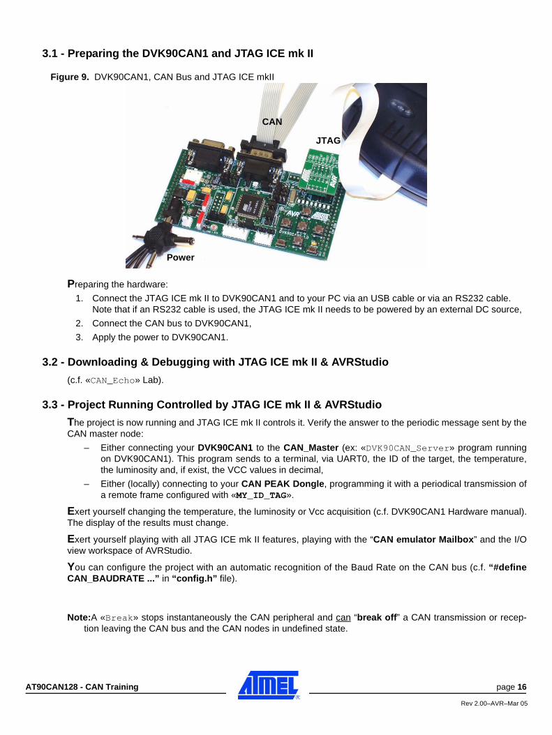
Figure 9. DVK90CAN1, CAN Bus and JTAG ICE mkII
Preparing the hardware:
1. Connect the JTAG ICE mk II to DVK90CAN1 and to your PC via an USB cable or via an RS232 cable.Note that if an RS232 cable is used, the JTAG ICE mk II needs to be powered by an external DC source,
2. Connect the CAN bus to DVK90CAN1,
3. Apply the power to DVK90CAN1.
3.2 - Downloading & Debugging with JTAG ICE mk II & AVRStudio
(c.f. «CAN_Echo» Lab).
3.3 - Project Running Controlled by JTAG ICE mk II & AVRStudio
The project is now running and JTAG ICE mk II controls it. Verify the answer to the periodic message sent by theCAN master node:
– Either connecting your DVK90CAN1 to the CAN_Master (ex: «DVK90CAN_Server» program runningon DVK90CAN1). This program sends to a terminal, via UART0, the ID of the target, the temperature,the luminosity and, if exist, the VCC values in decimal,
– Either (locally) connecting to your CAN PEAK Dongle, programming it with a periodical transmission ofa remote frame configured with «MY_ID_TAG».
Exert yourself changing the temperature, the luminosity or Vcc acquisition (c.f. DVK90CAN1 Hardware manual).The display of the results must change.
Exert yourself playing with all JTAG ICE mk II features, playing with the “CAN emulator Mailbox” and the I/Oview workspace of AVRStudio.
You can configure the project with an automatic recognition of the Baud Rate on the CAN bus (c.f. “#defineCAN_BAUDRATE ...” in “config.h” file).
Note:A «Break» stops instantaneously the CAN peripheral and can “break off” a CAN transmission or recep-tion leaving the CAN bus and the CAN nodes in undefined state.
CAN
JTAG
Power
AT90CAN128 - CAN Training page 16
Rev 2.00–AVR–Mar 05
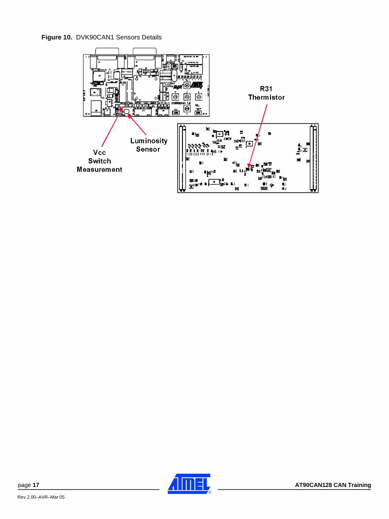
Figure 10. DVK90CAN1 Sensors Details
page 17 AT90CAN128 CAN Training
Rev 2.00–AVR–Mar 05
Lab 3: Song_Download
1 - INTRODUCTIONThe purpose of this “LAB” is to handle fragmented messages broadcasted by a CAN server. Because a messagecan be longer than a unitary CAN data message (8 bytes), a coding method is needed to be able to re-order theunitary CAN data messages into the original whole message.
The principle of this coding is to introduce fragmentation information in the data CAN message itself. In this example,this information is the index of the first byte into the original message. We also need two makers, one to indicate thestart of the message and an other one to indicate the end of this message. With a 16-bit index, messages up to65536+6 bytes can be carried away.
- The index “0” is chosen as the marker of start of message.- Because we don’t know the length of the message, the end of message marker will be chosen following thetype of the message. If the string “U8 my_string[20]{“abcdefghijklmnopqrst”}” is fragmented:
1. The first CAN message can be: ID=xxx,DLC=8,DATA=0x00,0x00,“a”,“b”,“c”,“d”,“e”,“f”
2. The second CAN message can be:ID=xxx,DLC=8,DATA=0x00,0x06,“g”,“h”,“i”,“j”,“k”,“l”
3. The third CAN message can be:ID=xxx,DLC=8,DATA=0x00,0x0C,“m”,“n”,“o”,“p”,“q”,“r”
4. The fourth CAN message can be:ID=xxx,DLC=5,DATA=0x00,0x12,“s”,“t”,0 and 0x00 is the ASCII End Of String ordinarily used.
This Lab uses a fragmentation template close to the above example. With a DVK90CAN1 board and the«Song_Server» project, the trainer is broadcasting up to 6 encoded song messages on the CAN bus. A burst ofCAN messages with the same ID (CAN2.0A) is sent on the CAN bus - one burst for one song. So, the song is sent asfragments on CAN bus (template of a song string is given in "audio_drv.c" file).
This Lab uses re-coded RTTTL ringtones as messages to send via CAN bus medium. The template of a song stringis given in "audio_drv.c" file.
- Example of song string (hexadecimal view):
String: "U16 ack_jingle[] = { 100, 110,E5, 150,E5, 150,E5, 800,C5, 0 };"(100, 110 ... are decimal integer or U16 ---- E5, C5, ... are for tone codes defined in "audio_drv.h" file).(100=0x0064, 110=0x006E, E5=0x02F6,150=0x0096, 1800=0x0320, C5=0x03BB)1. The first CAN message is: ID=123,DLC=8,DATA=00,00,64,00,6E,00,F6,02
(00,00 is the U16 index of the first element -64)
2. The second CAN message is: ID=123,DLC=8,DATA=00,06,96,00,F6,02,96,00(00,06 is the U16 index of the element -96)
3. The third CAN message is: ID=123,DLC=8,DATA=00,0C,F6,02,20,03,BB,03(00,0C is the U16 index of the element -F6)
4. The fourth CAN message is: ID=123,DLC=4,DATA=00,12,00,00(00,12 is the U16 index of the element -00)
5. (00,00 at the end means end of message, so DLC=4
The elements are U16. The first one is not used. The end of file marker is 0x0000 and it belongs to the song string.The index is decoded msByte first. In this Lab example, bursts are sent in an ordered way.
The trainee has to record and play the music chosen pushing on one of the buttons of its DVK90CAN1 board.
This exercise uses a fully working C code that should be completed (task 1), compiled and run (task 2).
Lab 3: Song_Download
AT90CAN128 - CAN Training page 18
Rev 2.00–AVR–Mar 05
2 - TASK 1Check your configuration ... and
2.1 - File to Use
«..\Lab_Session\Song_Download\main_song_download.c»
2.2 - Understand the Start of Routine1. The variable “start_of_song” is used to flag the start of the burst in reception.
The variable “on_going” is set until the end of message is detected.........................
// --- Set variables
start_of_song = 0;
on_going = 1;
........................
2. Initialize a pointer on U8 (string_rec) on the start address of a string of U16 (song_to_play).........................
// --- Set correspondance of string pointers
string_rec = (U8*)(&(song_to_play[0]));
........................
2.3 - Write the End of Routine
The trainee has to write the de-fragmentation routine in «main_song_download.c».
1. Initialize data for Rx and set the CAN descriptor in Rx configuration.........................
while(on_going)
{
// Init Rx data
// ...... put your code here ......
// --- Rx Command
// ...... put your code here ......
........................
2. Command an Rx operation on CAN bus.........................
// --- Enable Rx
// ...... put your code here ......
// --- Wait for Rx completed
// ...... put your code here ......
........................
3. Research of the index. Wait for the first fragment.........................
// --- Get index
// ...... put your code here ......
// --- Look for the first fragment
// ...... put your code here ......
........................
page 19 AT90CAN128 CAN Training
Rev 2.00–AVR–Mar 05

4. If first index (already) detected, record data up to the last fragment.........................
if (start_of_song)
{
for ( /* ...... put your code here ...... */ )
{
// --- Record data
// ...... put your code here ......
// --- Look for the last fragment
// ...... put your code here ......
}
}
........................
2.4 - S.O.S
Solution: «..\Lab_Solutions\Song_Download\main_song_download.c»
2.5 - Compiling & Linking with ImageCraft
For this guide it is required that ImageCraft ICCAVR version 6.31A (or newer) is installed on your computer.
We will:• Create a project in ImageCraft ICCAVR ( ..\Lab_Session\Song_Download\ directory).• Complete C source file following the directives• Build an object file for debugging in AVRStudio.• Build an Intel Hex file for your target part, the AT90CAN128.
The project is «Song_Download» project. Refer to «CAN_Echo» Lab or «DVK90CAN_Param» Lab for the wayto proceed without forgetting to compile all the libraries used in this project.
3 - TASK 2Run the «Song_Download» project on DVK90CAN1.
After the Power-ON, the program waits for DVK90CAN1 keyboard activity. Once a key is pushed the routine writtenby the trainee waits for the beginning of the burst of the wanted song (one song by key configuration). Then, theroutine records the song and the main core of the program plays it once. And so on.
Figure 11. Available Key Configuration
1. N(orth) Key
2. S(outh) Key
3. E(ast) Key
4. W(est) Key
5. C(enter) Key
6. E(ast) + W(est) Keys
AT90CAN128 - CAN Training page 20
Rev 2.00–AVR–Mar 05
3.1 - Preparing the DVK90CAN1 and JTAG ICE mk II
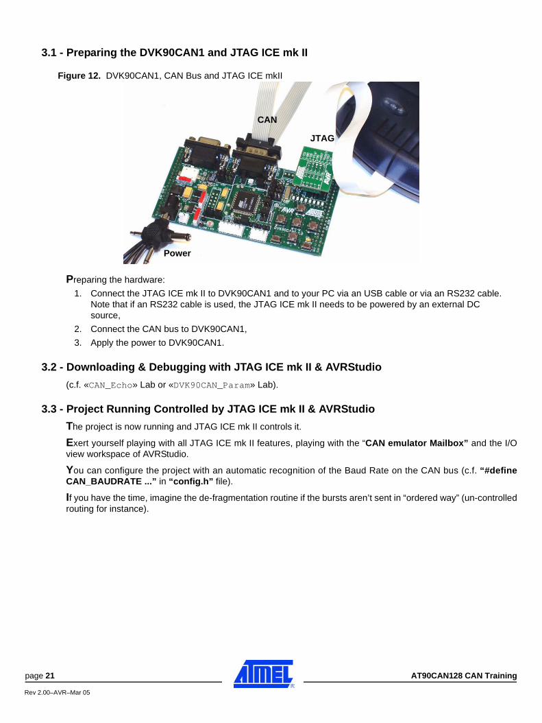
Figure 12. DVK90CAN1, CAN Bus and JTAG ICE mkII
Preparing the hardware:
1. Connect the JTAG ICE mk II to DVK90CAN1 and to your PC via an USB cable or via an RS232 cable.Note that if an RS232 cable is used, the JTAG ICE mk II needs to be powered by an external DC source,
2. Connect the CAN bus to DVK90CAN1,
3. Apply the power to DVK90CAN1.
3.2 - Downloading & Debugging with JTAG ICE mk II & AVRStudio
(c.f. «CAN_Echo» Lab or «DVK90CAN_Param» Lab).
3.3 - Project Running Controlled by JTAG ICE mk II & AVRStudio
The project is now running and JTAG ICE mk II controls it.
Exert yourself playing with all JTAG ICE mk II features, playing with the “CAN emulator Mailbox” and the I/Oview workspace of AVRStudio.
You can configure the project with an automatic recognition of the Baud Rate on the CAN bus (c.f. “#defineCAN_BAUDRATE ...” in “config.h” file).
If you have the time, imagine the de-fragmentation routine if the bursts aren’t sent in “ordered way” (un-controlledrouting for instance).
CAN
JTAG
Power
page 21 AT90CAN128 CAN Training
Rev 2.00–AVR–Mar 05
Annex 1: DVK90CAN_Server
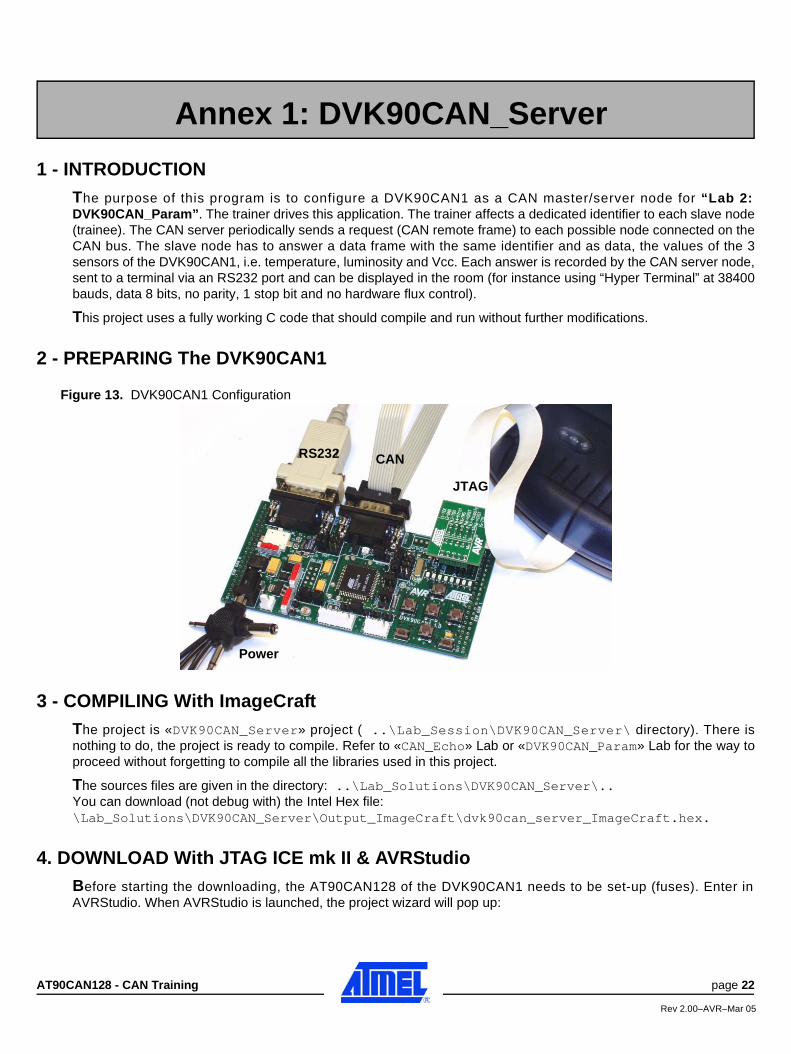
1 - INTRODUCTIONThe purpose of this program is to configure a DVK90CAN1 as a CAN master/server node for “Lab 2:DVK90CAN_Param”. The trainer drives this application. The trainer affects a dedicated identifier to each slave node(trainee). The CAN server periodically sends a request (CAN remote frame) to each possible node connected on theCAN bus. The slave node has to answer a data frame with the same identifier and as data, the values of the 3sensors of the DVK90CAN1, i.e. temperature, luminosity and Vcc. Each answer is recorded by the CAN server node,sent to a terminal via an RS232 port and can be displayed in the room (for instance using “Hyper Terminal” at 38400bauds, data 8 bits, no parity, 1 stop bit and no hardware flux control).
This project uses a fully working C code that should compile and run without further modifications.
2 - PREPARING The DVK90CAN1
Figure 13. DVK90CAN1 Configuration
3 - COMPILING With ImageCraftThe project is «DVK90CAN_Server» project ( ..\Lab_Session\DVK90CAN_Server\ directory). There isnothing to do, the project is ready to compile. Refer to «CAN_Echo» Lab or «DVK90CAN_Param» Lab for the way toproceed without forgetting to compile all the libraries used in this project.
The sources files are given in the directory: ..\Lab_Solutions\DVK90CAN_Server\..You can download (not debug with) the Intel Hex file:\Lab_Solutions\DVK90CAN_Server\Output_ImageCraft\dvk90can_server_ImageCraft.hex.
4. DOWNLOAD With JTAG ICE mk II & AVRStudioBefore starting the downloading, the AT90CAN128 of the DVK90CAN1 needs to be set-up (fuses). Enter inAVRStudio. When AVRStudio is launched, the project wizard will pop up:
Annex 1: DVK90CAN_Server
RS232 CAN
JTAG
Power
AT90CAN128 - CAN Training page 22
Rev 2.00–AVR–Mar 05
1. Select «Cancel» to output from the project wizard,
2. Select «Tools-->STK500/AVRISP/JTAG ICE-->STK500/AVRISP/JTAG ICE ...» to open the JTAG ICE mk II programming interface,
3. Select «AT90CAN128» device in the «Program» tab,
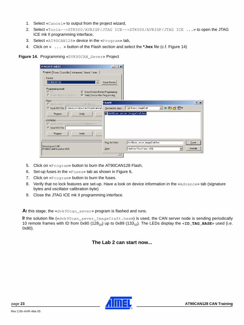
4. Click on « ... » button of the Flash section and select the *.hex file (c.f. Figure 14)
Figure 14. Programming «DVK90CAN_Sever» Project
5. Click on «Program» button to burn the AT90CAN128 Flash,
6. Set-up fuses in the «Fuses» tab as shown in Figure 6,
7. Click on «Program» button to burn the fuses.
8. Verify that no lock features are set-up. Have a look on device information in the «Advance» tab (signature bytes and oscillator calibration byte)
9. Close the JTAG ICE mk II programming interface.
At this stage, the «dvk90can_sever» program is flashed and runs.
If the solution file («dvk90can_sever_ImageCraft.hex») is used, the CAN server node is sending periodically10 remote frames with ID from 0x80 (12810) up to 0x89 (13310). The LEDs display the «ID_TAG_BASE» used (i.e.0x80).
The Lab 2 can start now...
page 23 AT90CAN128 CAN Training
Rev 2.00–AVR–Mar 05
Annex 2: Song_Server
1 - INTRODUCTION
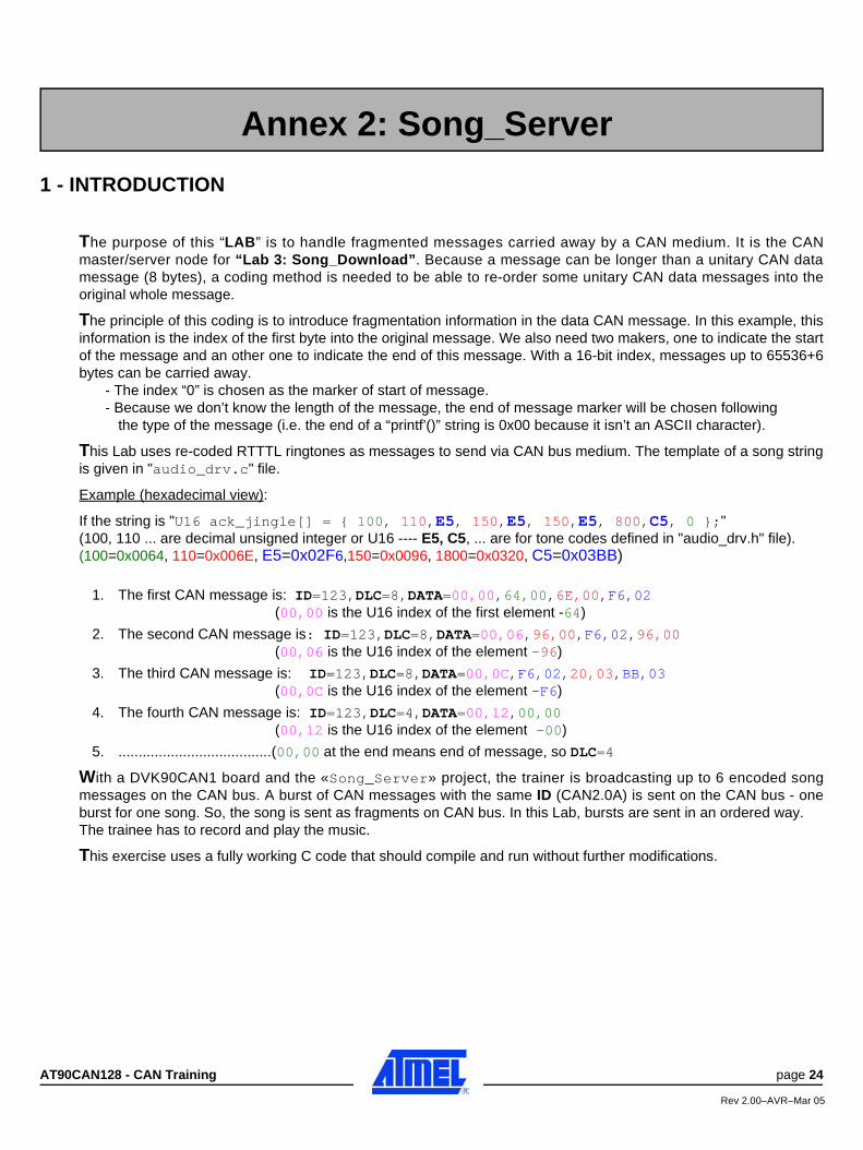
The purpose of this “LAB” is to handle fragmented messages carried away by a CAN medium. It is the CANmaster/server node for “Lab 3: Song_Download”. Because a message can be longer than a unitary CAN datamessage (8 bytes), a coding method is needed to be able to re-order some unitary CAN data messages into theoriginal whole message.
The principle of this coding is to introduce fragmentation information in the data CAN message. In this example, thisinformation is the index of the first byte into the original message. We also need two makers, one to indicate the startof the message and an other one to indicate the end of this message. With a 16-bit index, messages up to 65536+6bytes can be carried away.
- The index “0” is chosen as the marker of start of message.- Because we don’t know the length of the message, the end of message marker will be chosen following
the type of the message (i.e. the end of a “printf’()” string is 0x00 because it isn’t an ASCII character).
This Lab uses re-coded RTTTL ringtones as messages to send via CAN bus medium. The template of a song stringis given in "audio_drv.c" file.
Example (hexadecimal view):
If the string is "U16 ack_jingle[] = { 100, 110,E5, 150,E5, 150,E5, 800,C5, 0 };"(100, 110 ... are decimal unsigned integer or U16 ---- E5, C5, ... are for tone codes defined in "audio_drv.h" file).(100=0x0064, 110=0x006E, E5=0x02F6,150=0x0096, 1800=0x0320, C5=0x03BB)
1. The first CAN message is: ID=123,DLC=8,DATA=00,00,64,00,6E,00,F6,02(00,00 is the U16 index of the first element -64)
2. The second CAN message is: ID=123,DLC=8,DATA=00,06,96,00,F6,02,96,00(00,06 is the U16 index of the element -96)
3. The third CAN message is: ID=123,DLC=8,DATA=00,0C,F6,02,20,03,BB,03(00,0C is the U16 index of the element -F6)
4. The fourth CAN message is: ID=123,DLC=4,DATA=00,12,00,00(00,12 is the U16 index of the element -00)
5. ......................................(00,00 at the end means end of message, so DLC=4
With a DVK90CAN1 board and the «Song_Server» project, the trainer is broadcasting up to 6 encoded songmessages on the CAN bus. A burst of CAN messages with the same ID (CAN2.0A) is sent on the CAN bus - oneburst for one song. So, the song is sent as fragments on CAN bus. In this Lab, bursts are sent in an ordered way. The trainee has to record and play the music.
This exercise uses a fully working C code that should compile and run without further modifications.
Annex 2: Song_Server
AT90CAN128 - CAN Training page 24
Rev 2.00–AVR–Mar 05

2 - PREPARING the DVK90CAN1
Figure 15. DVK90CAN1 Configuration
3 - COMPILING With ImageCraftThe project is «Song_Server» project ( ..\Lab_Session\Song_Server\ directory). There is nothing to do, theproject is ready to compile. Refer to «CAN_Echo», «DVK90CAN_Param» or «DVK90CAN_Server» Lab’s for the wayto proceed without forgetting to compile all the libraries used in this project.
The sources files are given in the directory: ..\Lab_Solutions\Song_Server\..You can download (not debug with) the Intel Hex file:\Lab_Solutions\DVK90CAN_Server\Output_ImageCraft\song_server_ImageCraft.hex.
4. DOWNLOAD With JTAG ICE mk II & AVRStudio(c.f. “Annex 1: DVK90CAN_Server”).
At this stage, the «song_sever» program is flashed and runs.
If the solution file («song_sever_ImageCraft.hex») is used, the CAN server node is sending periodically 6bursts of frames with ID from 0x020 (03210) up to 0x025 (03710). The LED’s display 0x01 for ID 0x020, 0x02 for ID0x021, 0x04 for ID 0x022, etc...
The Lab 3 can start now...
CAN
JTAG
Power
page 25 AT90CAN128 CAN Training
Rev 2.00–AVR–Mar 05
Annex 3: CAN Library
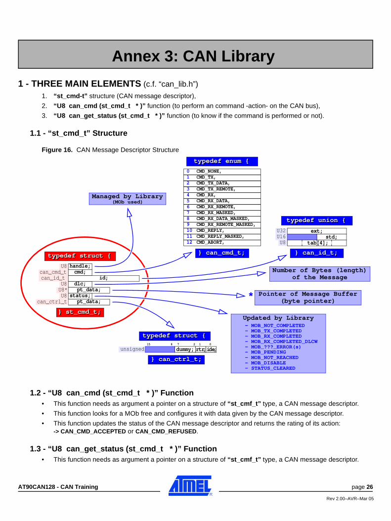
1 - THREE MAIN ELEMENTS (c.f. “can_lib.h”)
1. “st_cmd-t” structure (CAN message descriptor),
2. “U8 can_cmd (st_cmd_t * )” function (to perform an command -action- on the CAN bus),
3. “U8 can_get_status (st_cmd_t * )” function (to know if the command is performed or not).
1.1 - “st_cmd_t” Structure
Figure 16. CAN Message Descriptor Structure
1.2 - “U8 can_cmd (st_cmd_t * )” Function• This function needs as argument a pointer on a structure of “st_cmf_t” type, a CAN message descriptor.
• This function looks for a MOb free and configures it with data given by the CAN message descriptor.
• This function updates the status of the CAN message descriptor and returns the rating of its action:-> CAN_CMD_ACCEPTED or CAN_CMD_REFUSED.
1.3 - “U8 can_get_status (st_cmd_t * )” Function• This function needs as argument a pointer on a structure of “st_cmf_t” type, a CAN message descriptor.
Annex 3: CAN Library
U8 handle;
typedef struct {
CMD_TX,CMD_TX_DATA,CMD_TX_REMOTE,CMD_RX,Managed by Library
(MOb used)
Updated by Library- MOB_NOT_COMPLETED- MOB_TX_COMPLETED- MOB_RX_COMPLETED- MOB_RX_COMPLETED_DLCW- MOB_???_ERROR(s)- MOB_PENDING- MOB_NOT_REACHED- MOB_DISABLE- STATUS_CLEARED
U8 dlc;U8* pt_data;
can_id_t id;
U8 status;pt_data;can_ctrl_t
can_cmd_t cmd;
CMD_RX_DATA,CMD_RX_REMOTE,CMD_RX_MASKED,CMD_RX_DATA_MASKED,CMD_RX_REMOTE_MASKED,CMD_REPLY,CMD_REPLY_MASKED,CMD_ABORT,
typedef enum {typedef enum {
typedef struct { } can_cmd_t;} can_cmd_t;
} st_cmd_t;} st_cmd_t;
123456789101112
typedef union {typedef union {
} can_id_t;} can_id_t;
U16U32 ext;
std;U8 tab[4];
Number of Bytes (length)of the Message
Pointer of Message Buffer(byte pointer)
typedef struct {typedef struct {
unsigned dummy;
} can_ctrl_t;} can_ctrl_t;
15 8 7 2 1 0
tr;r de;i
*
CMD_NONE,0
AT90CAN128 - CAN Training page 26
Rev 2.00–AVR–Mar 05
• With the “handle” information of the CAN message descriptor, this function returns a status about currentaction of the MOb:-> CAN_STATUS_COMPLETED, CAN_STATUS_NOT_COMPLETED or CAN_STATUS_ERROR.
1.4 - Example of Using
//.......
U8 i;
U8 buffer[8];
st_cmd_t message;
//.......
message.pt_data = &buffer[0];
message.cmd = CMD_RX;
while(can_cmd(&message) != CAN_CMD_ACCEPTED);
while(can_get_status(&msg) == CAN_STATUS_NOT_COMPLETED);
//.......
2 - OTHER FUNCTION(S)
2.1 - “U8 can_init (U8 mode)” Function• This function performs a full initialization of the CAN controller. This function also accepts an automatic
recognition of the Baud Rate on the CAN bus (c.f. “#define CAN_BAUDRATE ...” in “config.h” file).
• The first time in the program, this function performs needs “0x00” as argument. If the automatic recognition ofthe Baud Rate is used and some fails are detected, new calling(s) to this function may be necessary (thefunction will try other values than those already tested), it will need “0x01” as argument.
• Especially when automatic recognition of the Baud Rate is used, this function returns “0x00” when none BaudRate has been found, else “0x01” is returned.
Example:
void main (void)
{U8 temp;
temp = 0;//.......while(1){
temp = can_init(temp);if (temp != 0){
//.......your_program(); // If too many errors, output from “your_program()”
}else{
printf(“No synchro, exit.\r\n”); break;}
}while(1); // Error loop
page 27 AT90CAN128 CAN Training
Rev 2.00–AVR–Mar 05

Notes:
AT90CAN128 - CAN Training page 28
Rev 2.00–AVR–Mar 05